

|
The Skip Gram "G-Styk"
|
|
|
| Parts List | Tools List | G-Styk First Test Video | G-Styk Final Test Video |
|
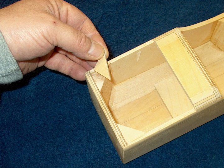
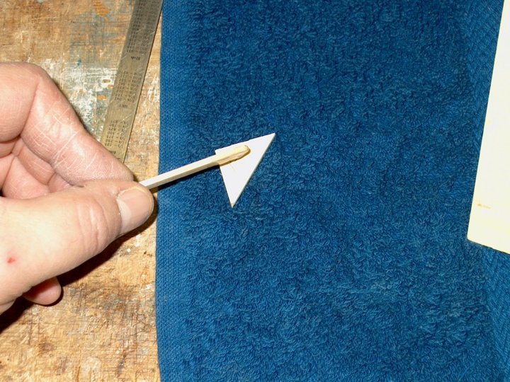
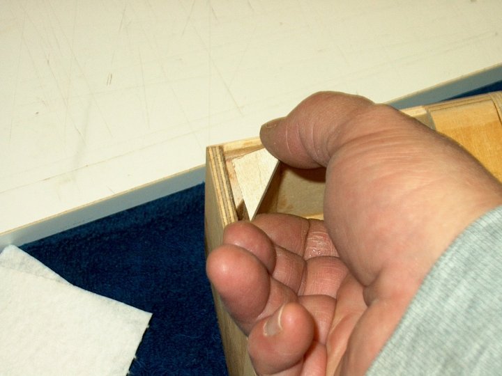
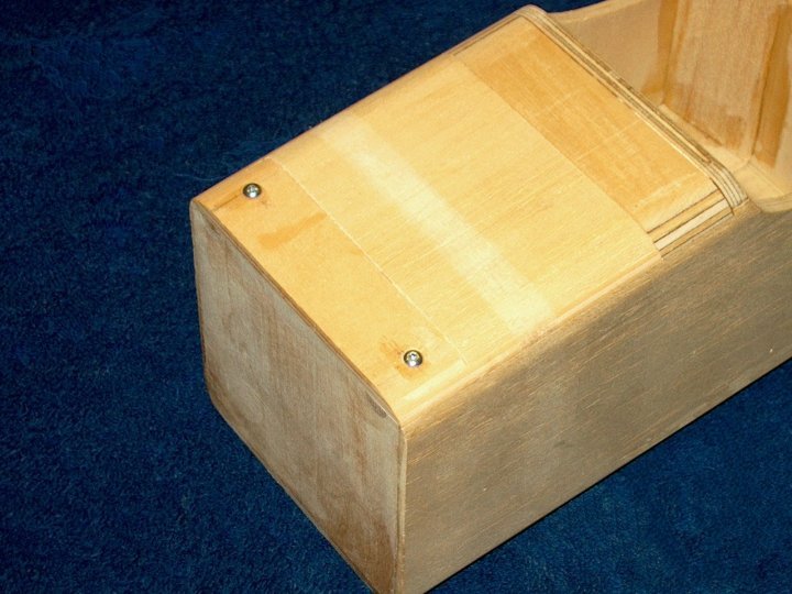
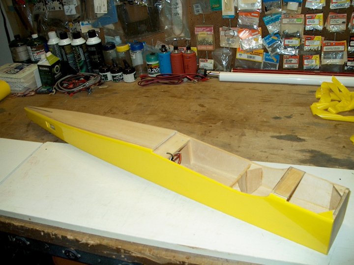
We began with the fuselage. Two 1/8" ply triangles were cut to cap the balsa triangle and some support so the screws
have more bite into the hatch mount area
|
|
|
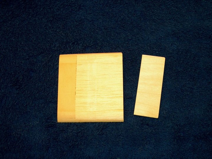
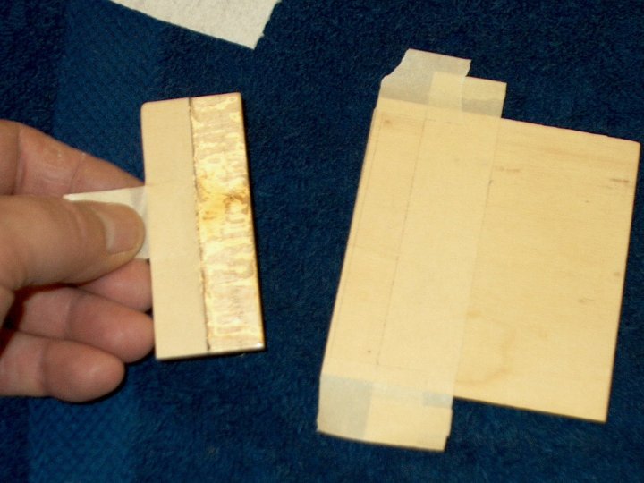
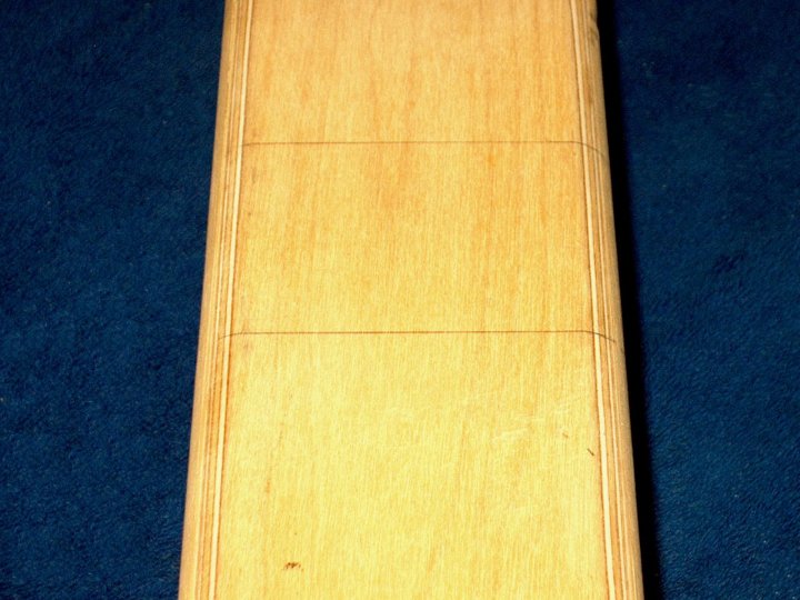
A piece of scrap 1/16" ply was cut 1 1/4" wide to install as a rear tongue for the top hatch. 1/8" ply has been
used in the past, but 1/16" will do the trick and keep it a bit lighter
|
|
|
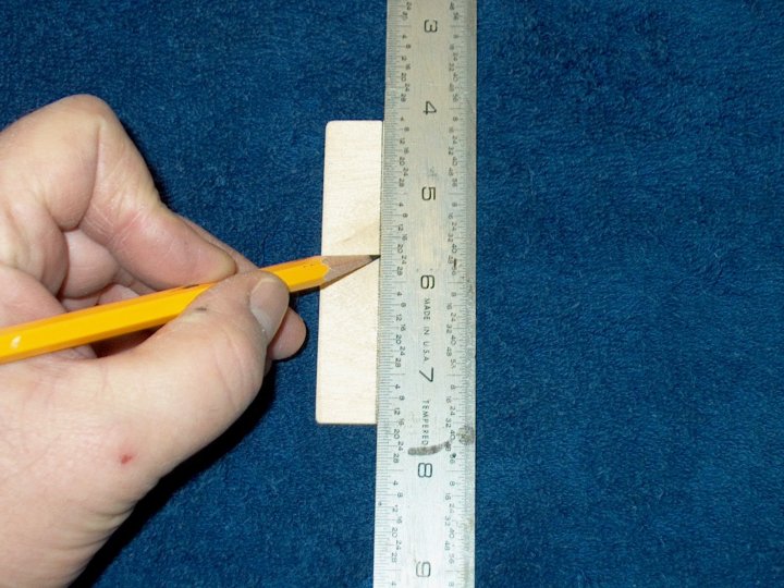
A center line was drawn down the middle of the ply tongue
|
|
|
The tongue was fit to the bottom rear of the hatch and masking tape was used to mark the outline. The tongue was
also taped at the center line. This allows us to remove the tape, as well as the excess epoxy that lands on it
|
|
|
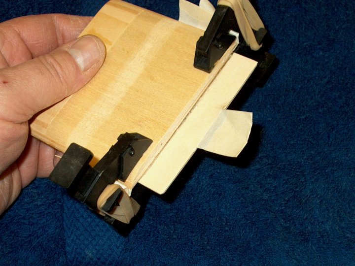
A thin film of epoxy was applied to both pieces, then they were aligned and joined and the tape was removed, leaving
a clean wood surface
|
|
|
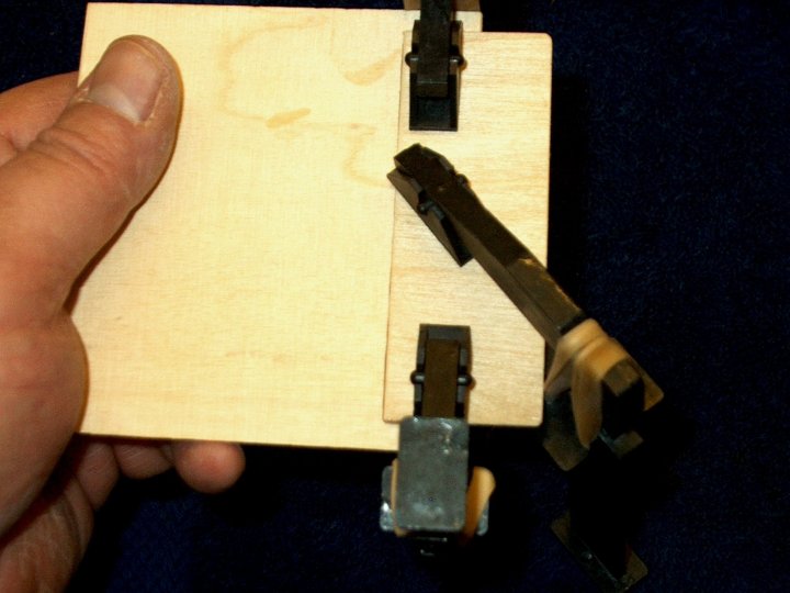
Clamps were used, including a center clamp so the plate would not warp while the glue set
|
|
|
Epoxy was applied to each triangle piece, as well as the top of the balsa triangle in the fuselage, giving them
a chance to soak it up for a good joint
|
|
|
Each triangle piece was installed and held in place until the epoxy set
|
|
|
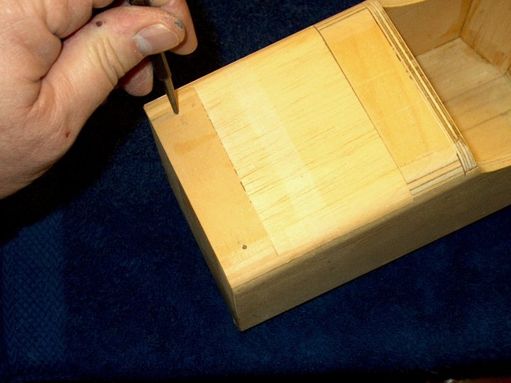
Marks were made on the top hatch, 1/2" from the front and sides for the mounting screws
|
|
|
The top hatch was taped in place and the two holes were drilled small enough to allow the
wood screws to cut teeth into the plywood triangle pieces. The hole areas were lightly
soaked with thin CA to prevent splintering prior to drilling
|
|
|
The hatch holes were bored out larger so the 4-40 wood screws could fit through
|
|
|
The wing was fitted and mounted on the fuselage
|
|
|
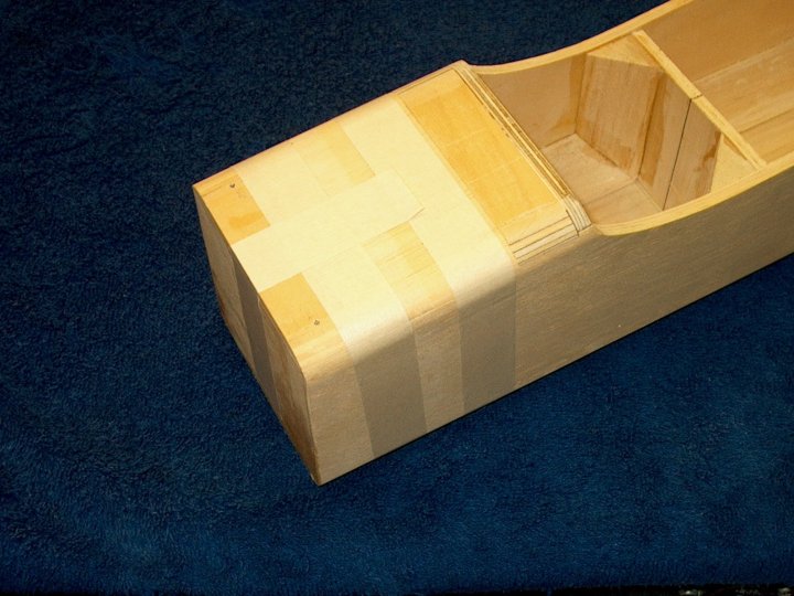
Top hatch for the fuselage was installed
|
|
|
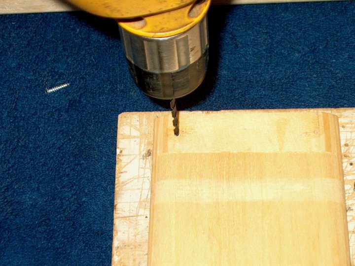
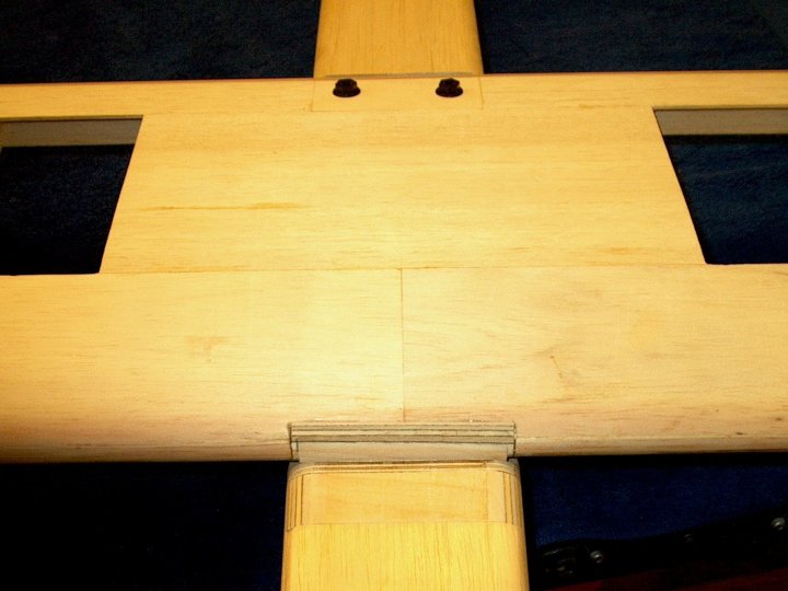
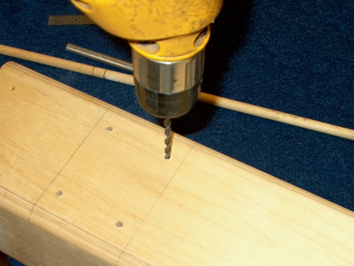
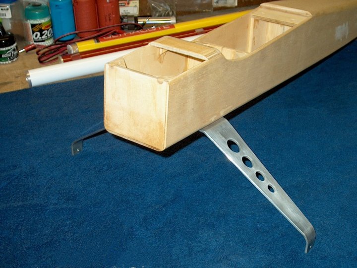
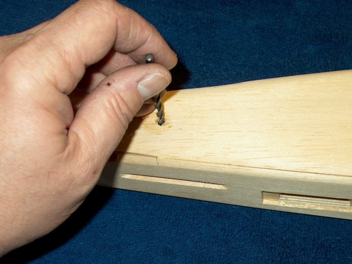
The landing gear was marked for mounting holes, 1/4" inward from the front and rear and 2 1/4" wide. The gear was
drilled with a bit one size smaller than a 4-40 bolt
|
|
|
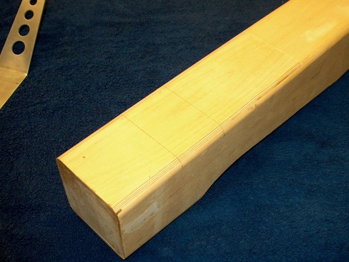
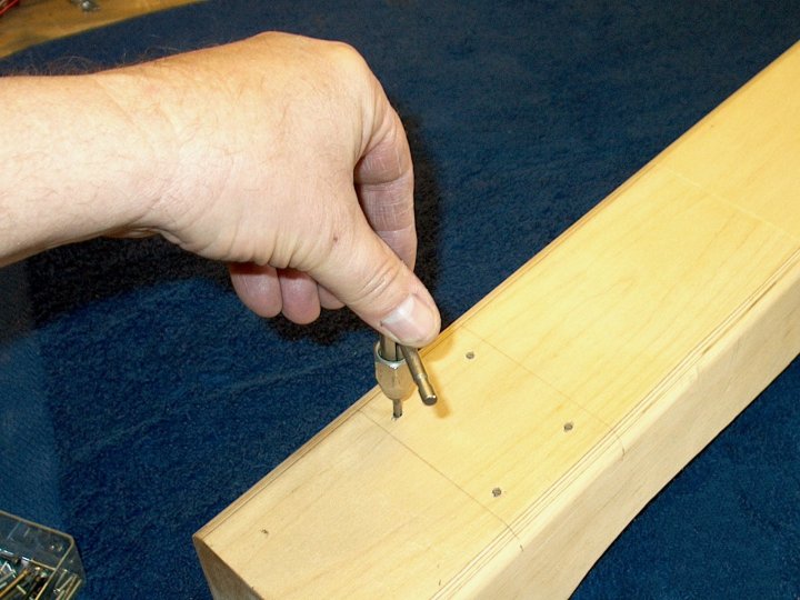
Viewing inside the fuselage, we made a mark on the outside for the rear location of the 1/4" gear mounting block.
A line was drawn from this mark and another line was drawn 2 1/2" in front of it, as this is the length of the block
|
|
|
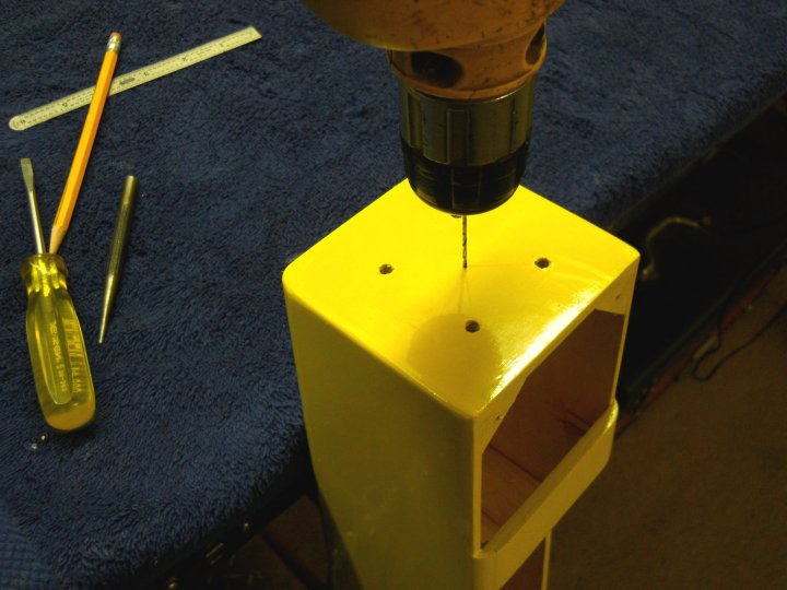
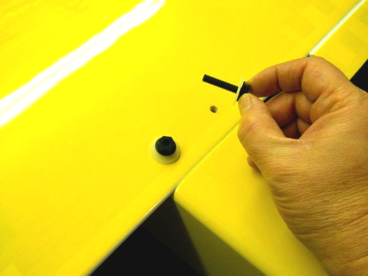
Outside starter mark can be seen on the lower right, curving over the edge of the bottom. The gear was centered and
holes were drilled through the fuselage, using the gear holes as a guide
|
|
|
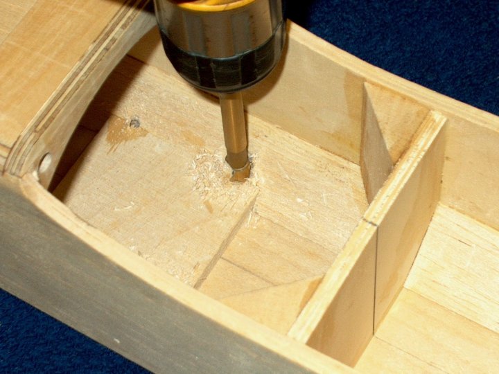
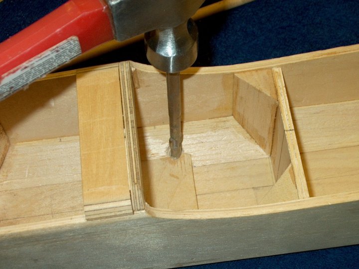
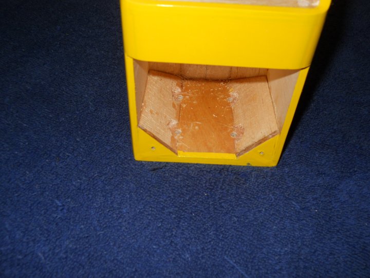
A Forstner bit was used to remove the excess balsa triangle and allow clearance for the blind nuts
|
|
|
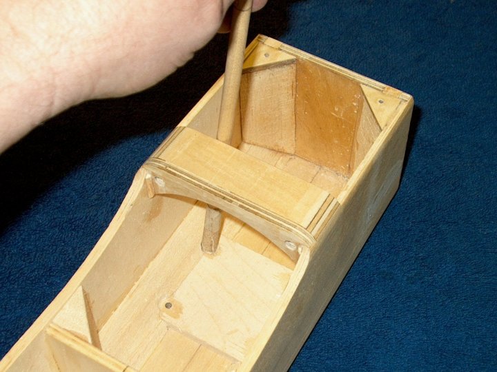
The area was cleaned up with a piece of sandpaper wrapped around a wood dowel
|
|
|
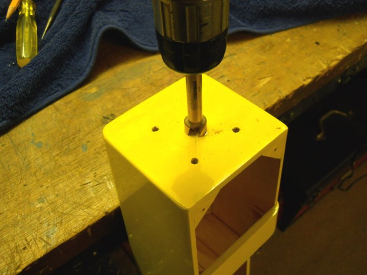
The holes were opened in the fuselage to compensate for the larger diameter of the blind nuts
|
|
|
Each blind nut was intalled and tapped in place
|
|
|
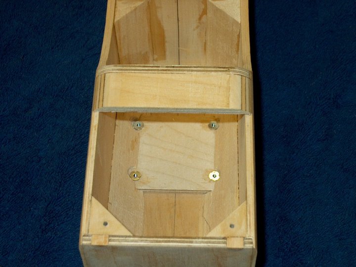
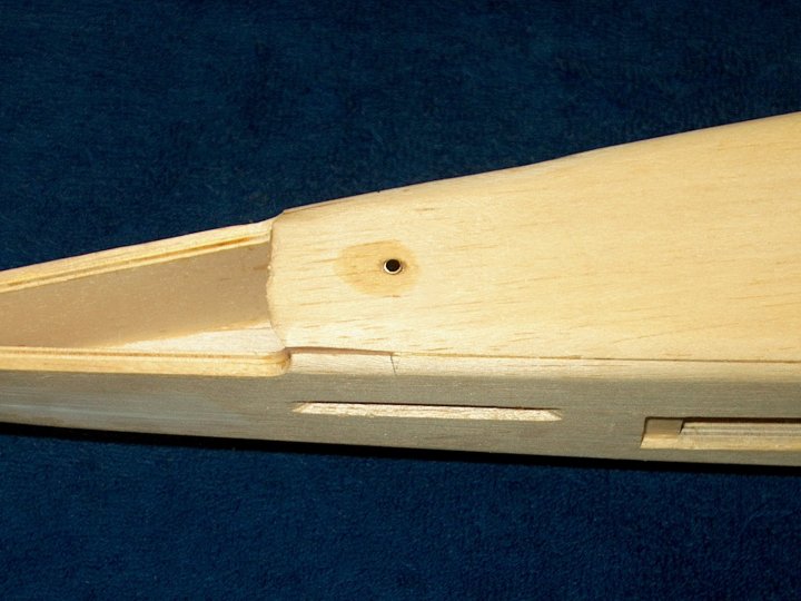
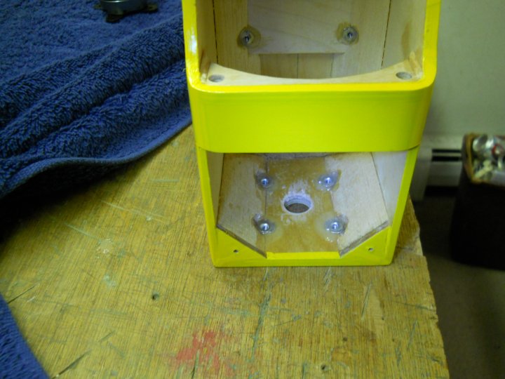
Blind nuts shown installed
|
|
|
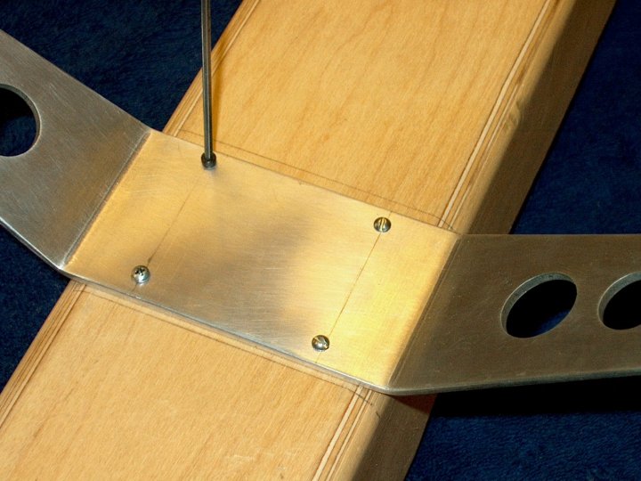
The landing gear was installed to help pull the blind nuts down flush and tight
|
|
|
Pic showing the landing gear installed. Epoxy was placed around the outside edges of the blind nuts inside the
fuselage to prevent them from pushing out
|
|
|
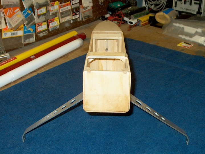
Landing gear shown installed. It was removed after the epoxy was placed on the blind nuts so any extra glue would
not glue the bolts in the nuts
|
|
|
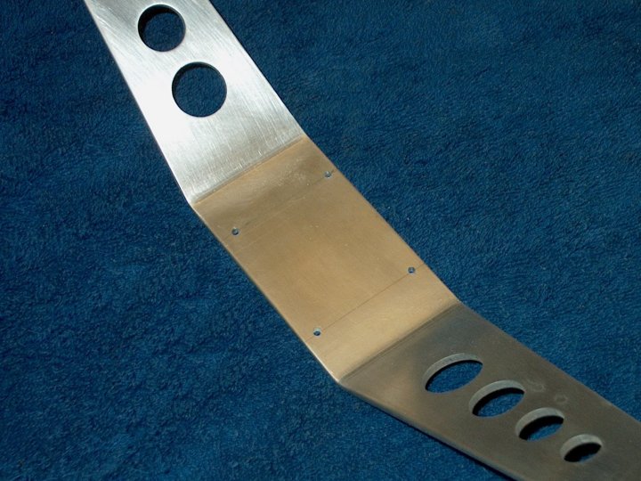
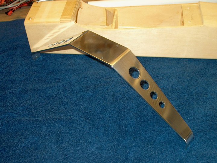
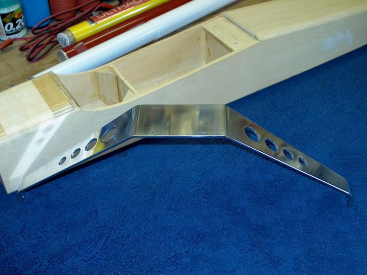
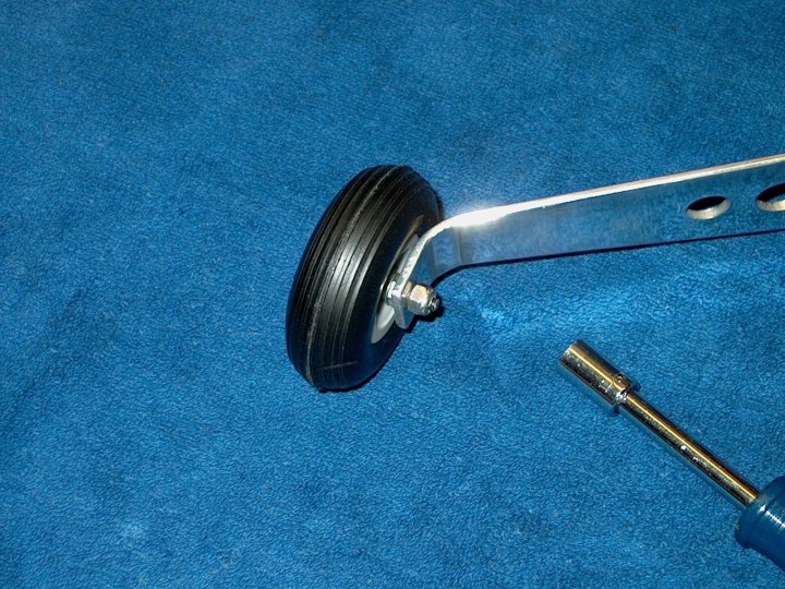
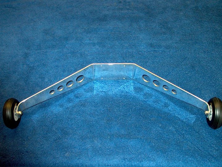
The landing gear was removed and polished with Mother's Aluminum Wheel Polish
|
|
|
Another view of the polished landing gear
|
|
|
Once the epoxy set, the blind nuts were tapped out with a 4-40 tap to insure there was no glue left on the threads
|
|
|
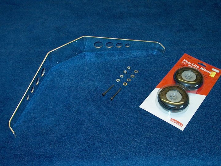
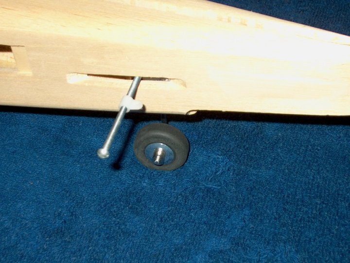
Lightweight wheels and 8-32 x 1 1/2" bolts make up the rest of the main landing gear parts
|
|
|
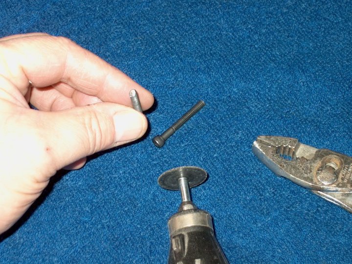
8-32 x 1 1/2" bolts were cut down to 1 1/4" in length
|
|
|
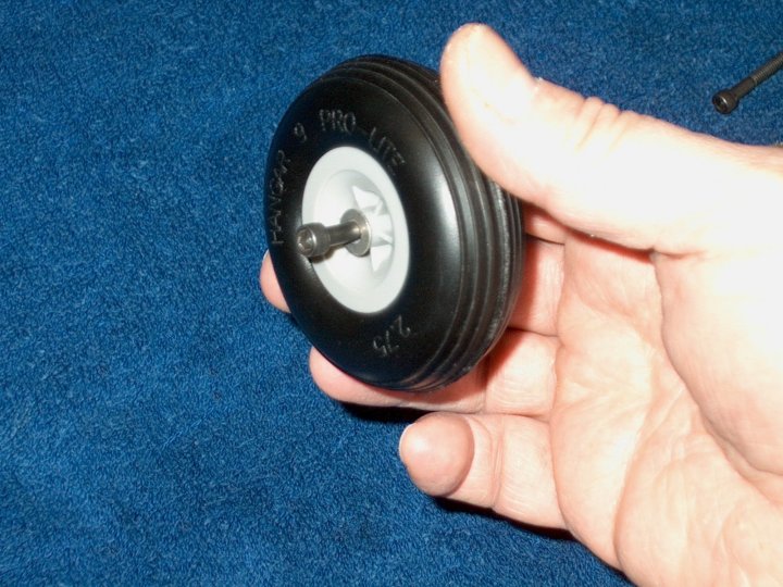
Bolt and flat washer are installed on the outside of the wheel
|
|
|
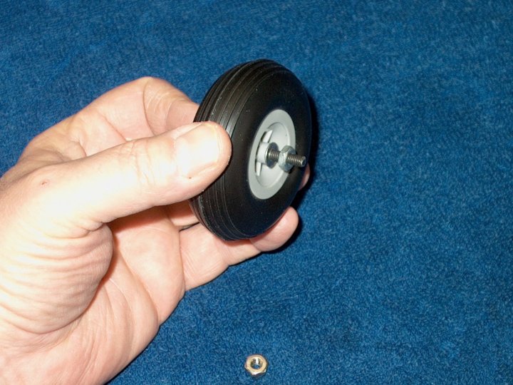
A washer and standard nut are installed on the other side of the wheel. A dab of LokTite was used at the threads
where the nut will tighten.
|
|
|
I tapped out the gear for 8-32 threads, so the bolt was screwed on and the inner nut tightened against the gear,
while the wheel was checked for free spinning. A Nyloc nut was installed to cap off the assembly and tightened
|
|
|
The Main landing gear assembly is shown completed
|
|
|
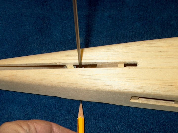
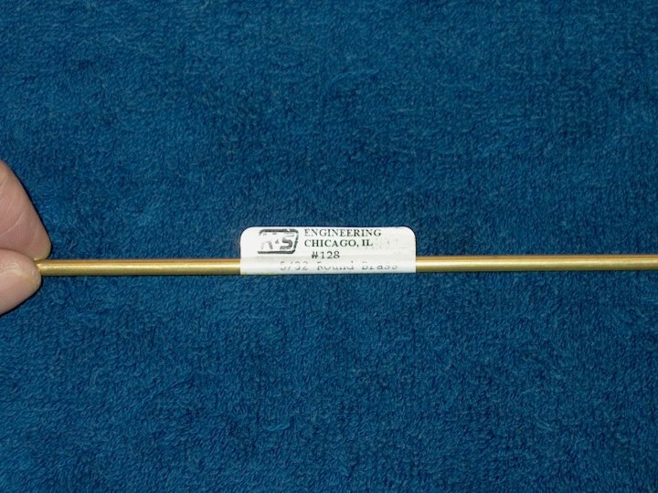
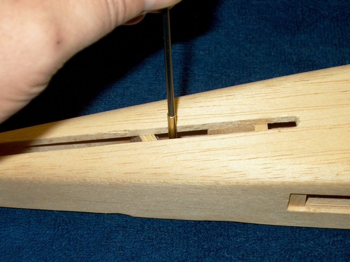
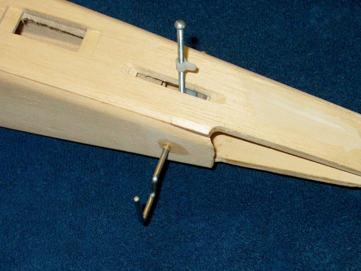
a 5/32" tube and 1/8" steel rod were inserted in the tailwheel hole and a mark was made on the bottom of the fuselage
on both sides to locate the exit point of the tailwheel wire
|
|
|
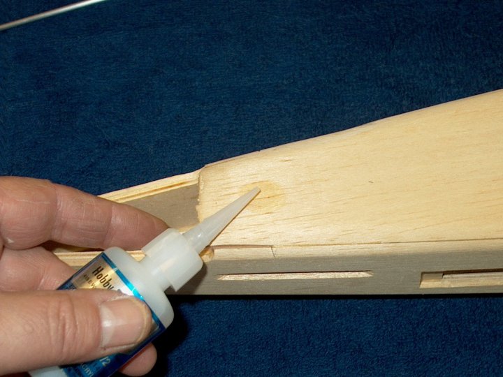
CA was added to prevent splintering of the balsa in the tailwheel wire exit area
|
|
|
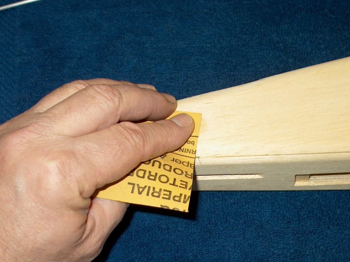
The area was sanded smooth
|
|
|
A piece of 5/32" brass tubing was cut and will adapt the 1/8" tailwheel rod to the gear block
|
|
|
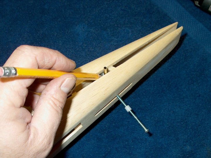
The tube was inserted into the top of the pre-installed nylon gear block and a 1/8" drill was inserted into the tube.
A hole was drilled for the wire exit
|
|
|
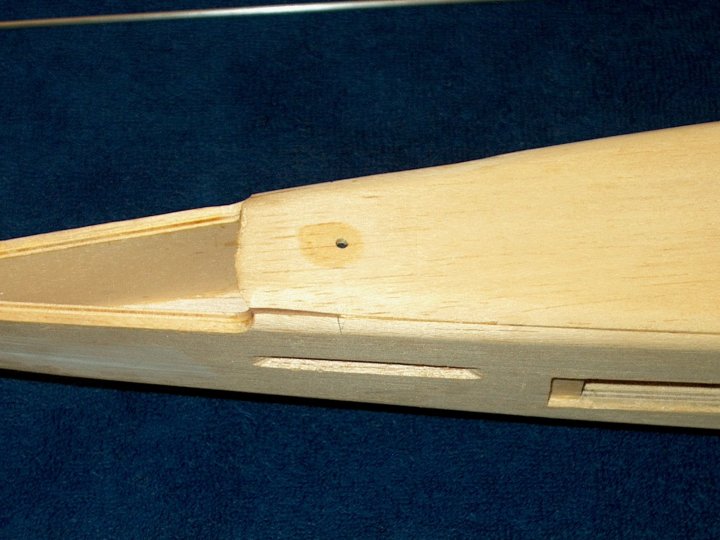
This view shows the hole location after drilling
|
|
|
A 5/32" drill was used to open the hole up to the right diameter for the brass tube
|
|
|
The tube was inserted flush to the bottom of the fuselage
|
|
|
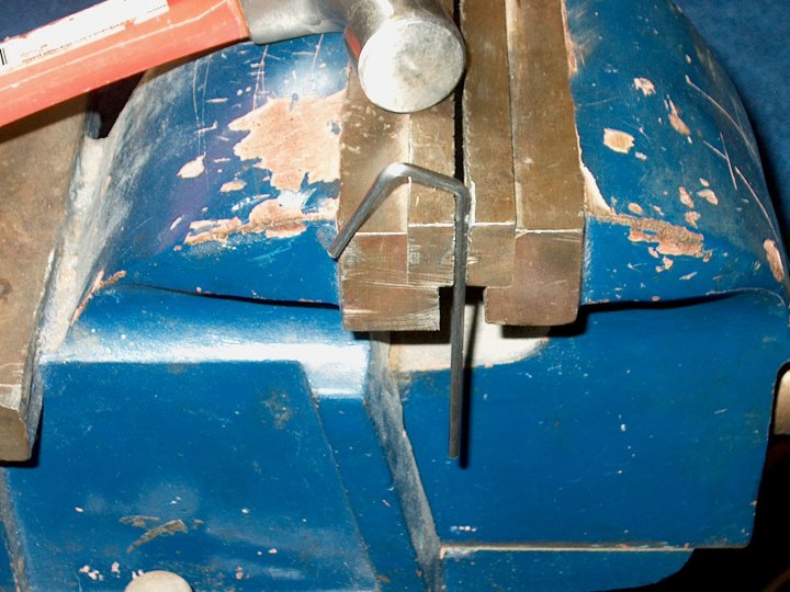
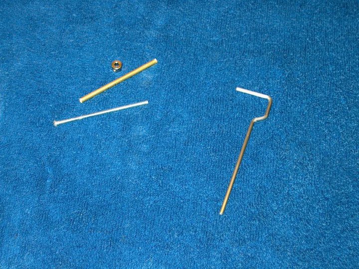
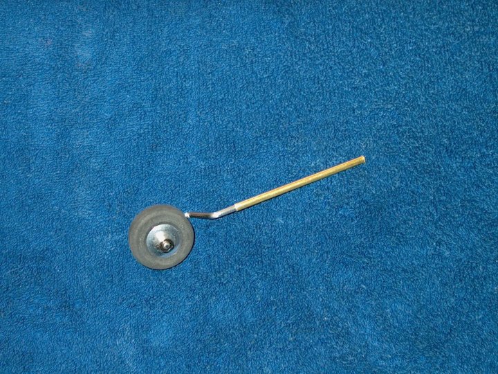
A new tailwheel wire was fabricated from 1/8" wire
|
|
|
5/32" OD brass sleeve was cut for the tailwheel wire and a 6-32 x 2"+ bolt is used as a steering rod
|
|
|
The assembly is test fitted
|
|
|
The 1 1/4" tailwheels are sold with 3/32" holes, so the hole was drilled out to 1/8"
|
|
|
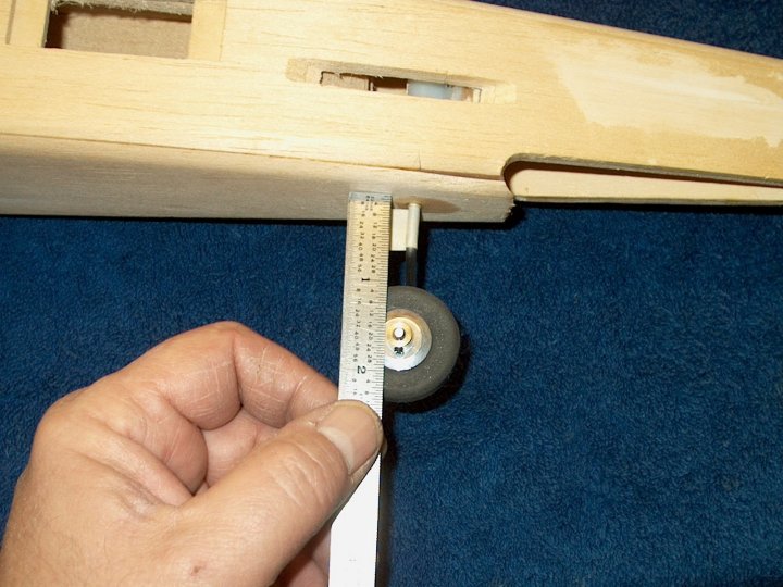
The tailwheel and brass tube were installed on the wire, then inserted with a 1" clearance between the bottom of the fuselage
and top of the wheel. Tape was used to mark the location of the brass tube
|
|
|
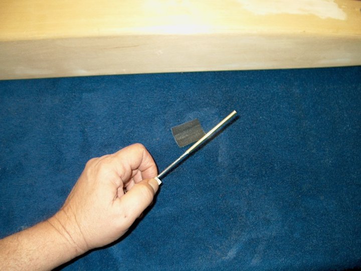
The wire was roughed up with coarse metal sandpaper, then the brass tube was epoxied on the rod up to the tape marker
|
|
|
Tailwheel assembly shown ready to cut to length
|
|
|
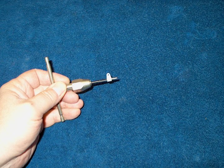
An EZ-Adjust Horn Bracket was bored with a 6-32 tap
|
|
|
The tailwheel was mounted and the top was marked for cutting
|
|
|
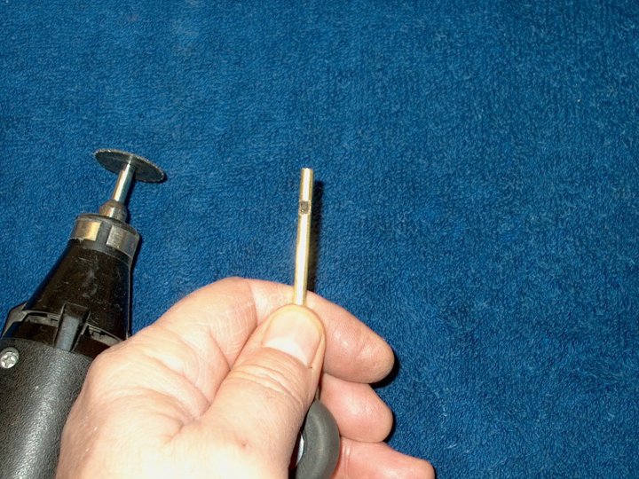
The tailwheel wire was cut to a length flush with the top of the mount and a slot was ground on the rod so the
control arm won't slip on the tailwheel shaft
|
|
|
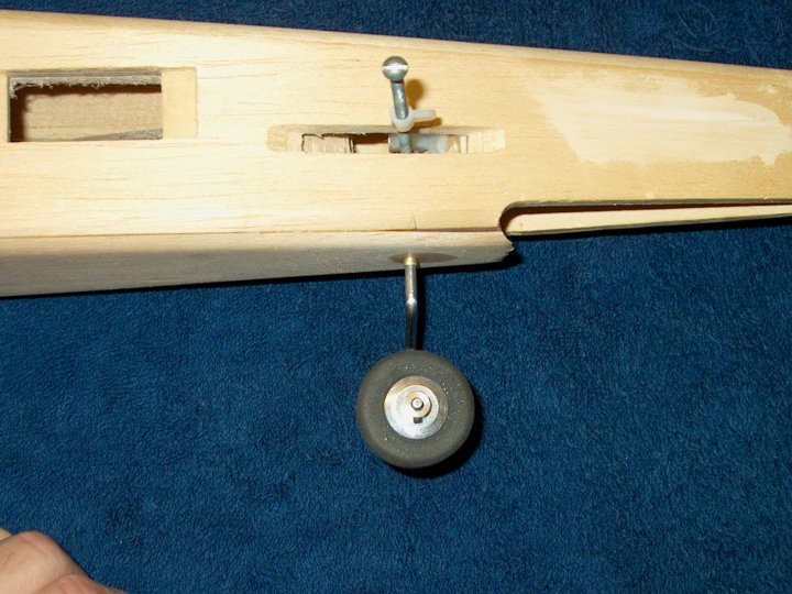
The tailwheel assembly was installed and check for final fit
|
|
|
Tailwheel assembly shown completed, minus the trimming of the 6-32" all thread...I need to check with Skip and see
how long the allthread needs to protrude from the model
|
|
|
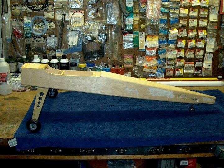
A view of the model with all landing gear installed
|
|
|
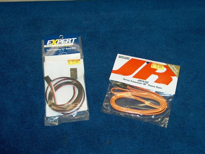
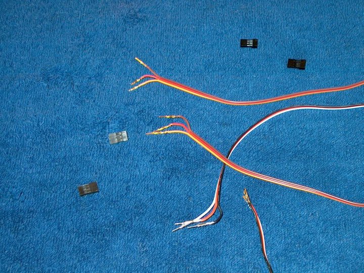
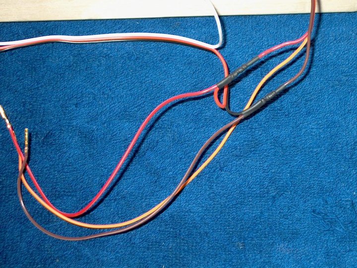
Heavy duty 36" long servo extensions are used for wiring the Elevator and Rudder servos. I used two different kinds
as this is a 4 wire system; the route tubing is made for 4 wires, so I wanted a 4th color for the second signal wire
|
|
|
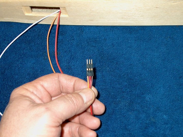
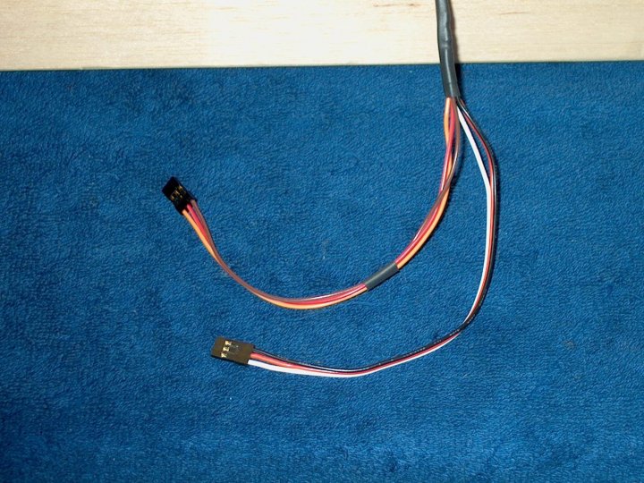
The connectors are removed for routing through the feed tube, as well as soldering
|
|
|
Four wires of different colors are used for the harness. The power wires will be shared between the servos
|
|
|
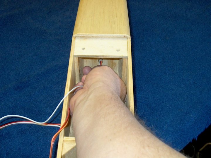
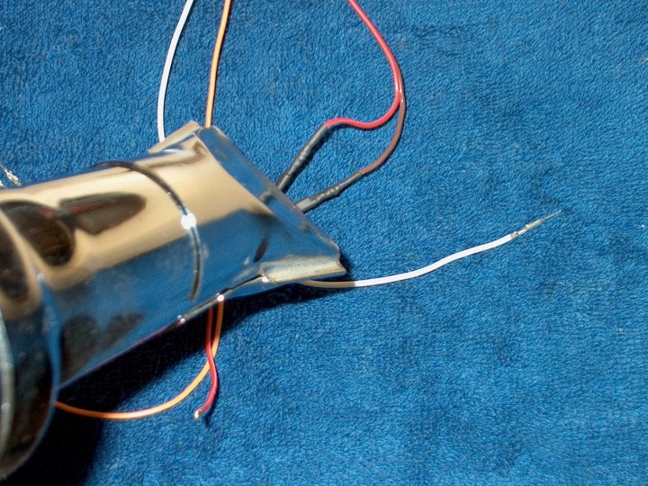
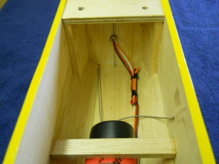
Wires are routed through the feed tube to the rear of the fuselage
|
|
|
The wires are pulled through one of the servo holes
|
|
|
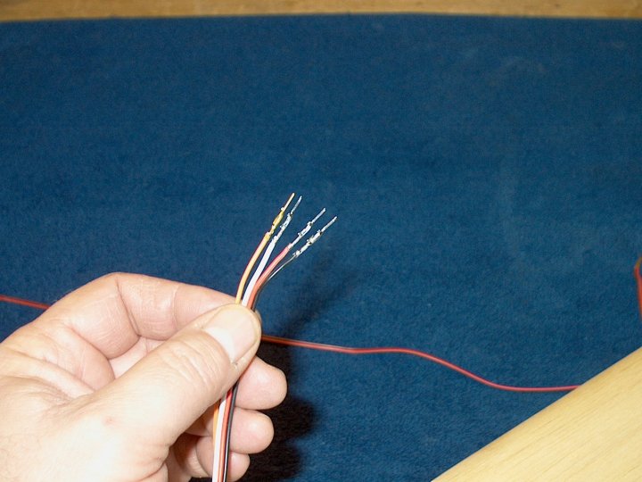
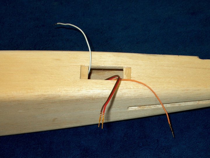
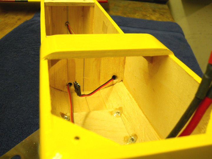
The first wire set shown how it will look after construction
|
|
|
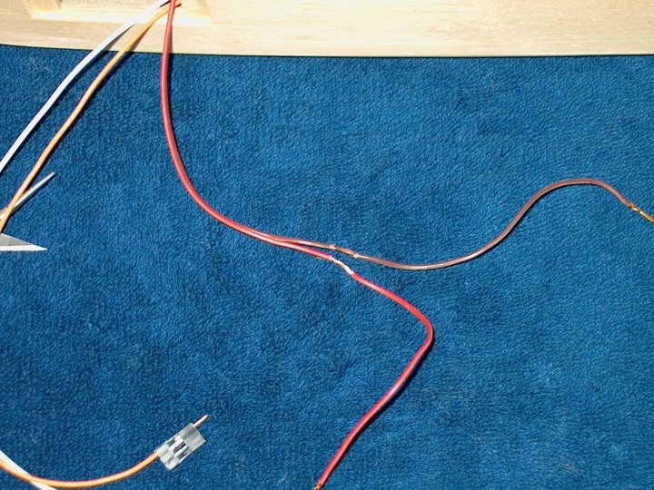
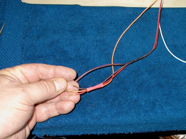
The positive and negative wires for the primary run are carefully stripped of insulation
|
|
|
The piggyback power wires for the second servo are stripped with about 1 1/4" of wire showing
|
|
|
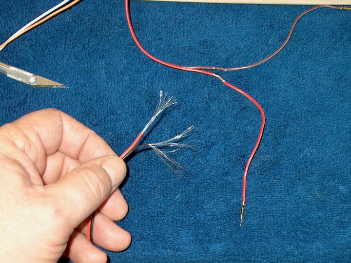
The primary wires are "fanned out" and the piggyback wire will be pushed through as shown for good contact
|
|
|
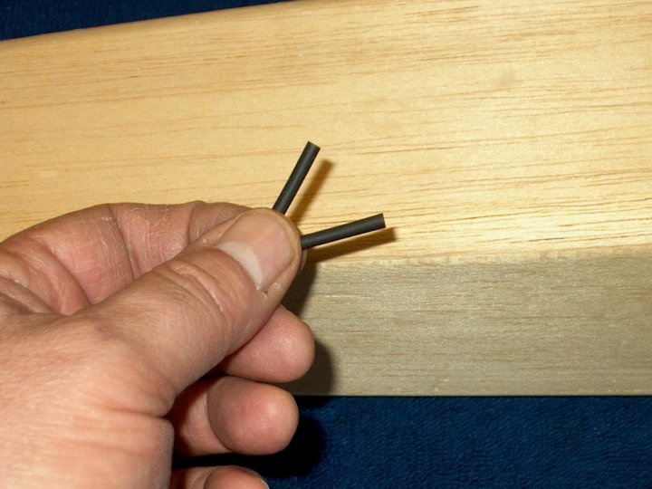
Two 1" long pieces of heat shrink are cut, then slid over each primary wire
|
|
|
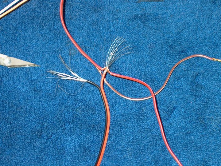
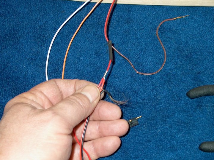
The piggyback wires are pushed through the fanned primary wires as previously shown and then carefully wrapped from
the front(single wire side) to the back(double wire side) so the wrap holds the fanned wires together nice and tight
and allows for good contact
|
|
|
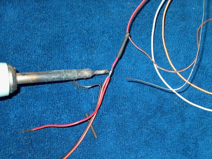
The joint is soldered
|
|
|
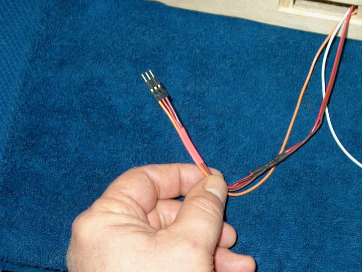
The heat shrink tubing was slid over and shrunk with a heat gun
|
|
|
The second power wire was spliced like the first
|
|
|
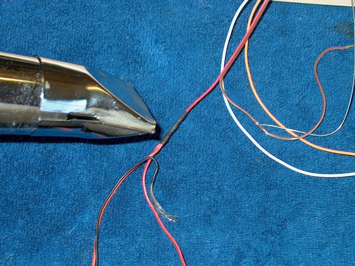
A 1" piece of heat shrink was slid over the primary wire set and held in place
|
|
|
A heat gun was used to shrink the tubing
|
|
|
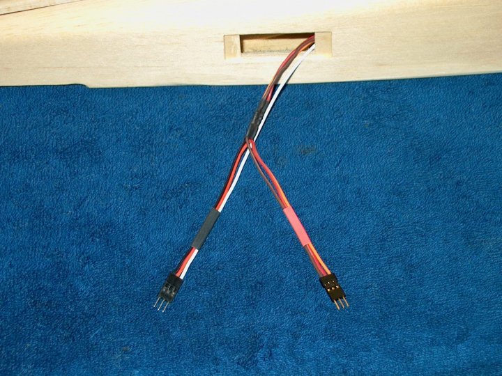
This view shows both wire sets completed at the rear of the airplane, with connectors installed and waiting
on plastic sleeves
|
|
|
The front wires were spliced in the same manner as the rear ones
|
|
|
Front wire set was completed...time to sand the fuselage and start covering!
|
|
|
Fuselage was sanded smooth to prep for covering
|
|
|
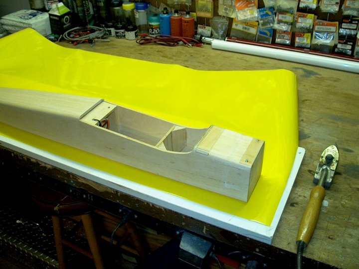
The fuselage was set on the covering and the yellow Ultracoat was cut to size for the botttom
|
|
|
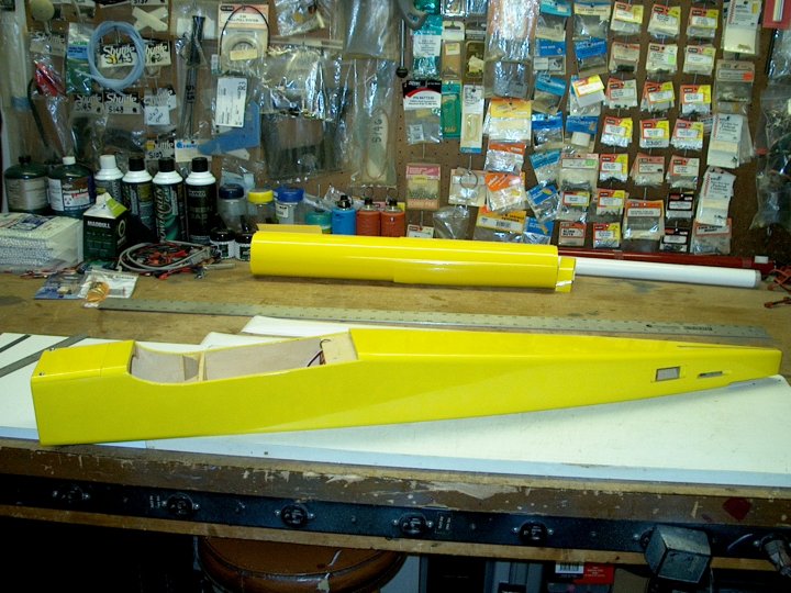
The bottom and right side are shown completed
|
|
|
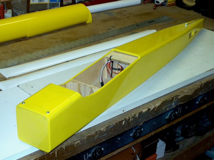
The fuselage has been completely covered in yellow Ultracoat
|
|
|
Side view showing servo area at the right was also covered in detail
|
|
|
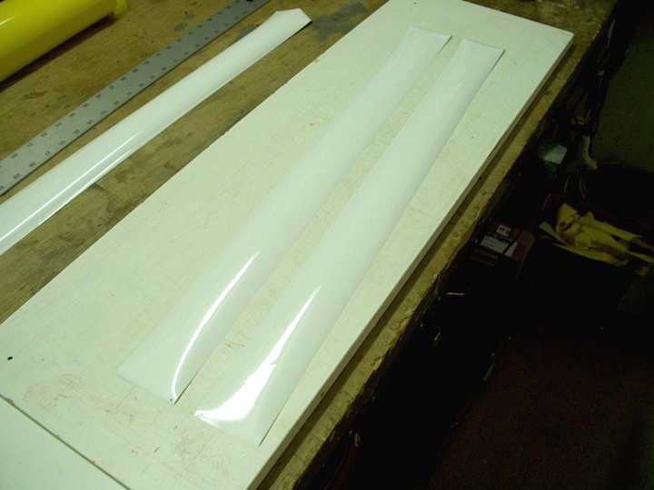
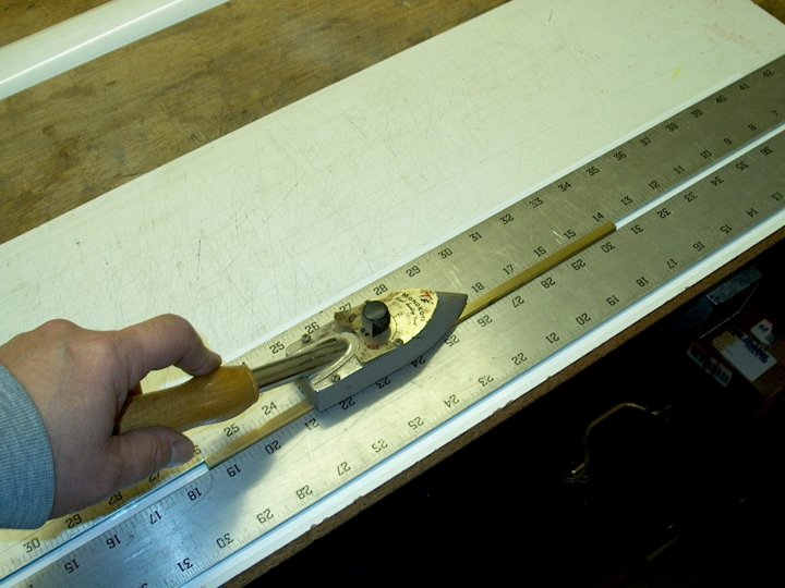
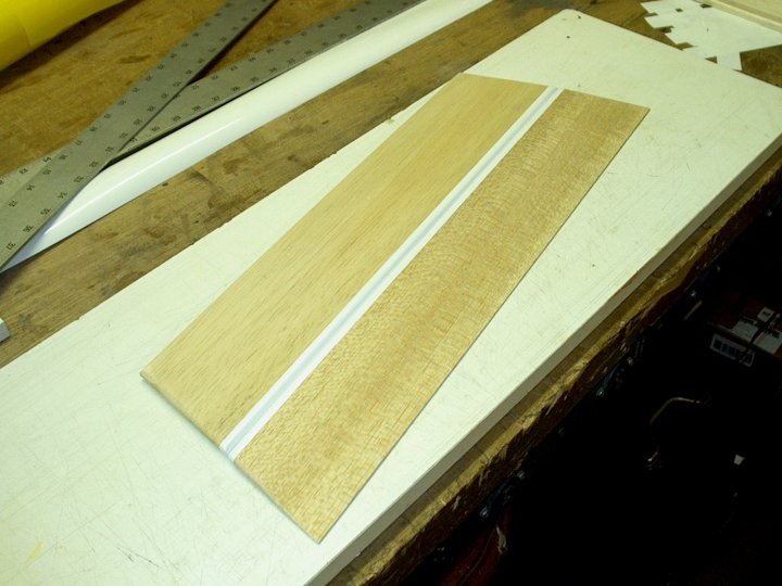
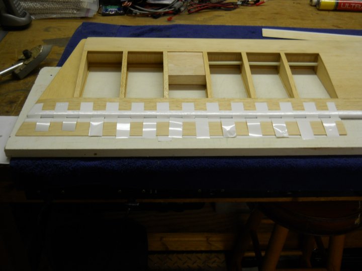
The model will use "Monokote" hinges for all control surfaces. We begin by cutting two pieces of white Monokote wide
enough for the Elevator and each strip is 2 1/2" wide
|
|
|
Two long yardsticks are used to align the material and you invert one piece and position it with a 1/4" overlap at the
center. One piece should be pointing sitcky side up and the other sticky side down. A piece of 1/4" square brass
tubing is polished, then inserted between the two rulers and heated with a model iron. This "seams" the two pieces
of Monokote with a 1/4" wide, strong seam.
|
|
|
A closeup view, showing the two pieces of Monokote seamed at the centerline
|
|
|
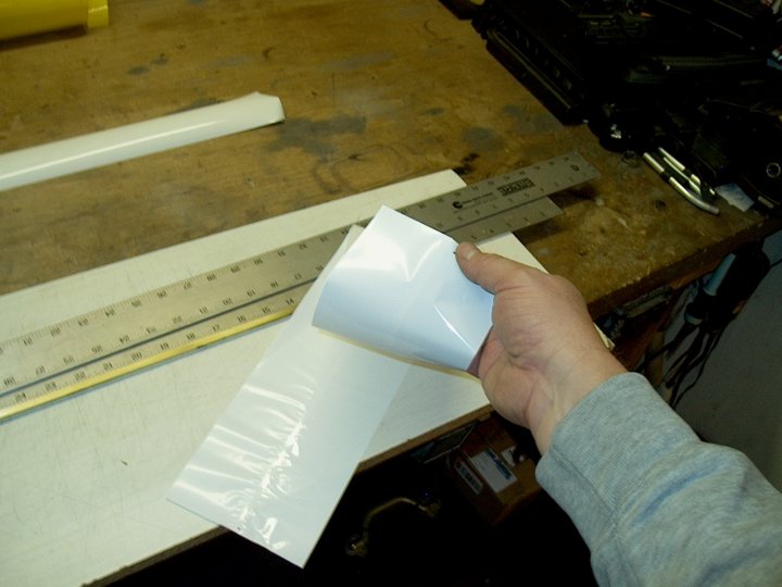
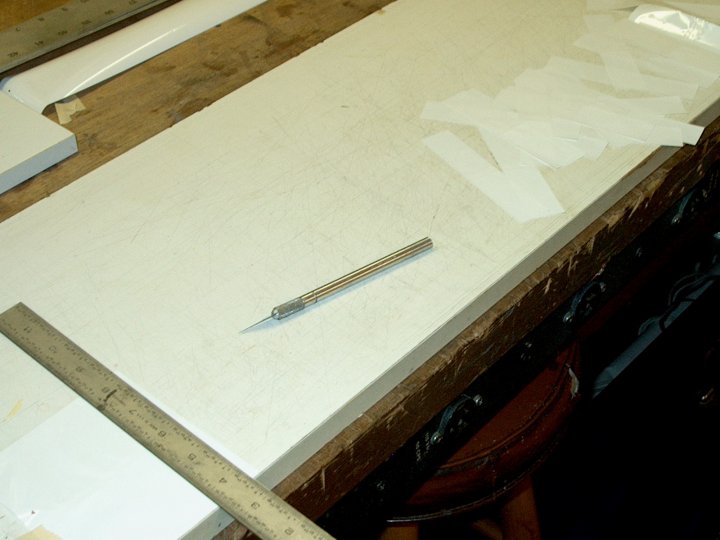
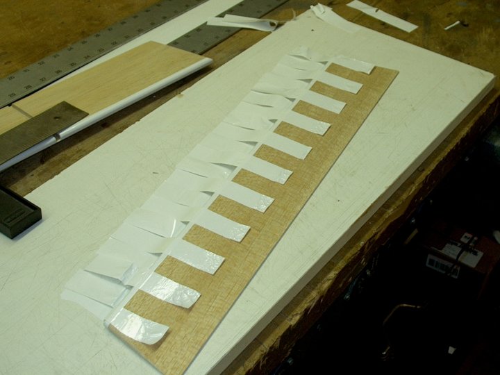
The finished hinge material is cut into 1" wide strips
|
|
|
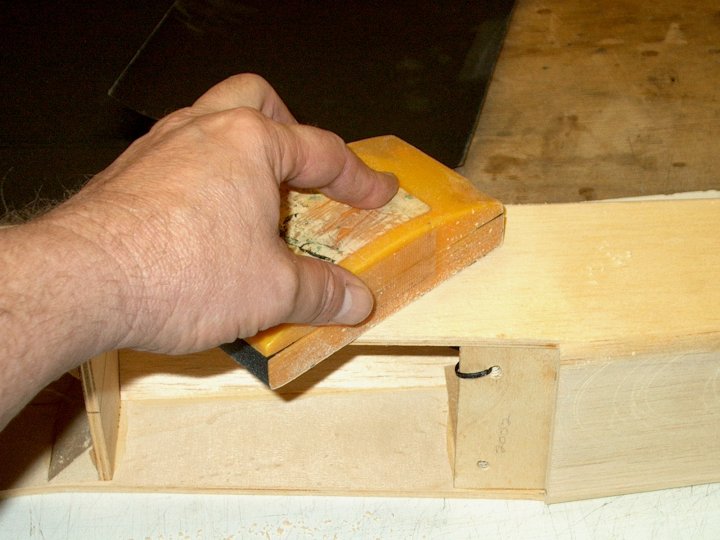
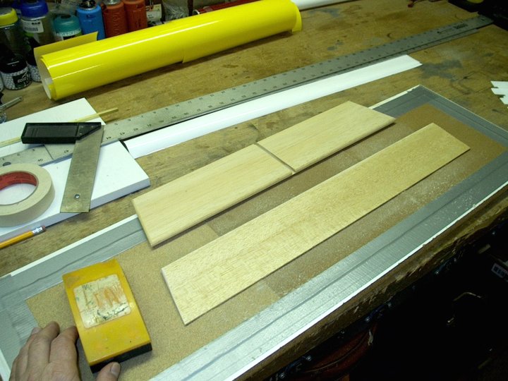
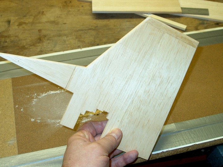
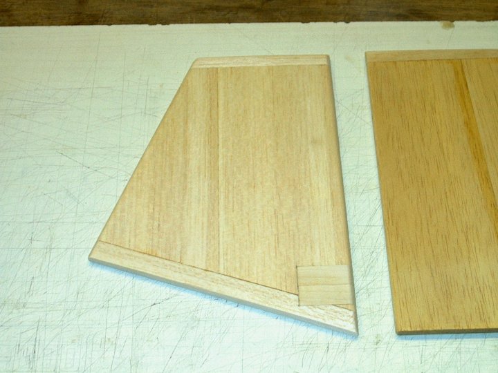
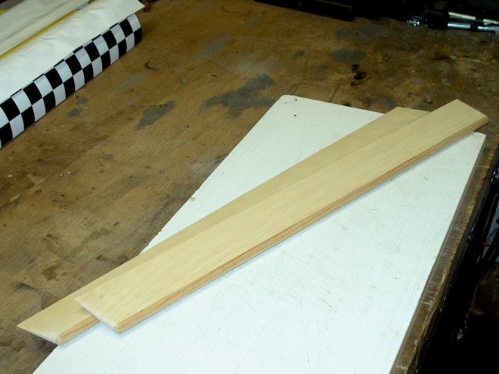
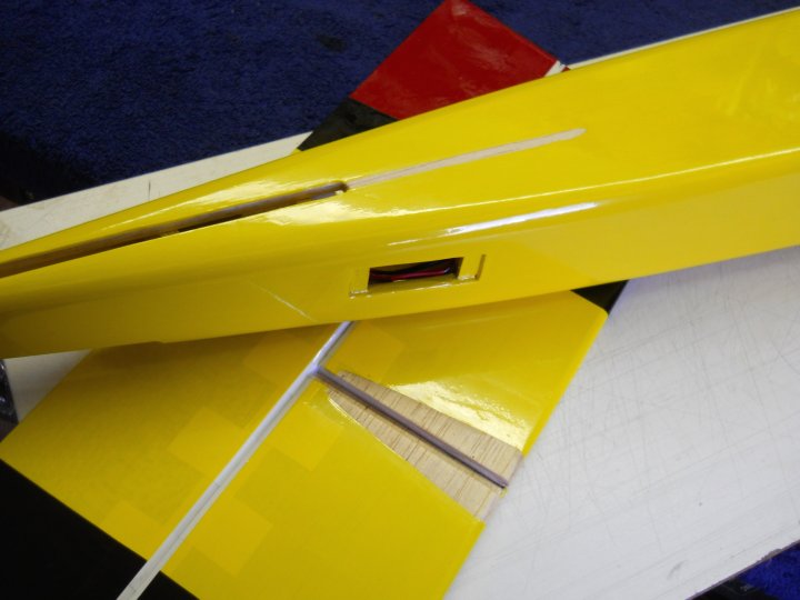
The Elevator was cut on the left to match the angle of the Stab's side, then beveled round like the stab. The leading
edge was sanded using the taped down sandpaper shown under the balsa
|
|
|
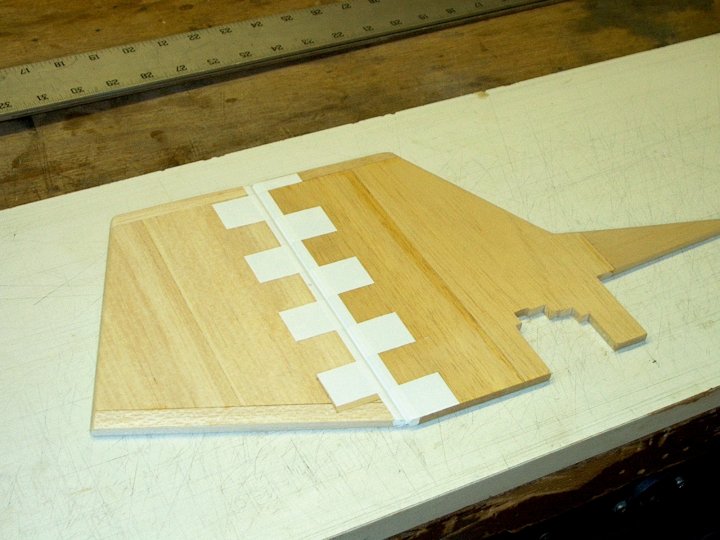
The trailing edge of the horizontal stab and leading edge of the Elevator were covered in the hinge area
|
|
|
Hinges were ironed on the Elevator
|
|
|
The Elevator hinges were ironed to the Stab and the excess was trimmed off, leaving about 1" of each hinge attached
|
|
|
The Vertical Stab was sanded and edges were beveled
|
|
|
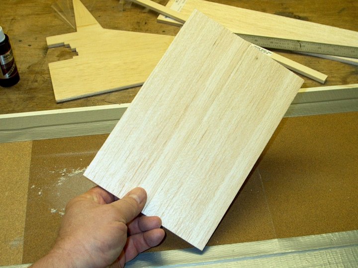
A Rudder needed to be constructed from 1/4" balsa The top and bottom are capped with 1/2" strips of 1/4" balsa
|
|
|
This view shows the bottom and top of the Rudder shaped, beveled and capped. A Birch block was blended and epoxied
into the bottom front of the rudder for strength around the area where the control horns will reside. Both pieces
were fine sanded, ready to cover
|
|
|
The Vertical Stab and Rudder were capped with a strip of Monokote, similar to the Elevator and Horizontal Stab.
Also, the hinges were added in the same manner as the Elevator/Stab combo
|
|
|
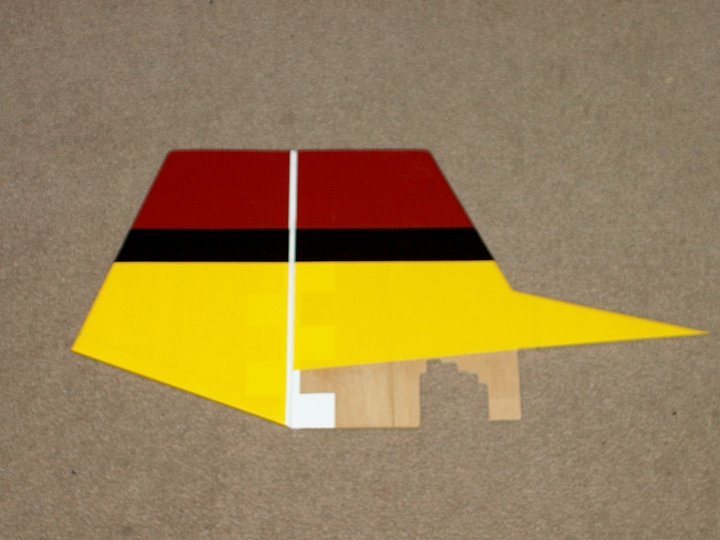
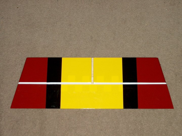
The Vertical Stab and Rudder were covered to Skip's specifications. I tried to get it as close as possible to his pic
|
|
|
The Horizontal Stab and Elevator were covered per the pic
|
|
|
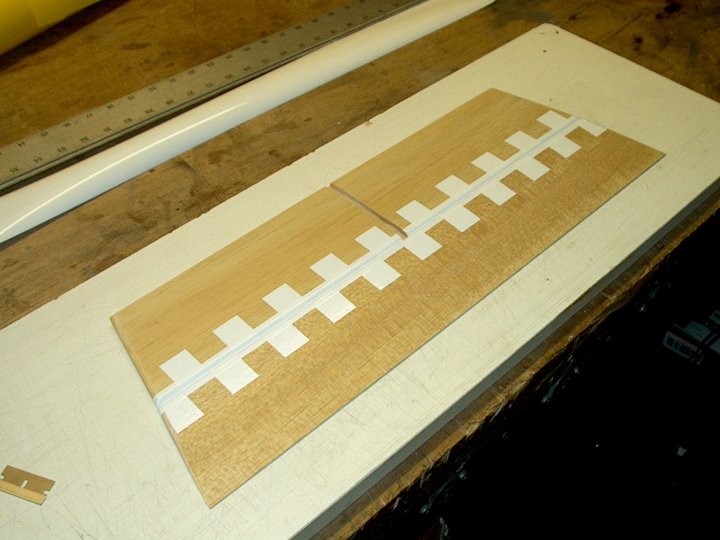
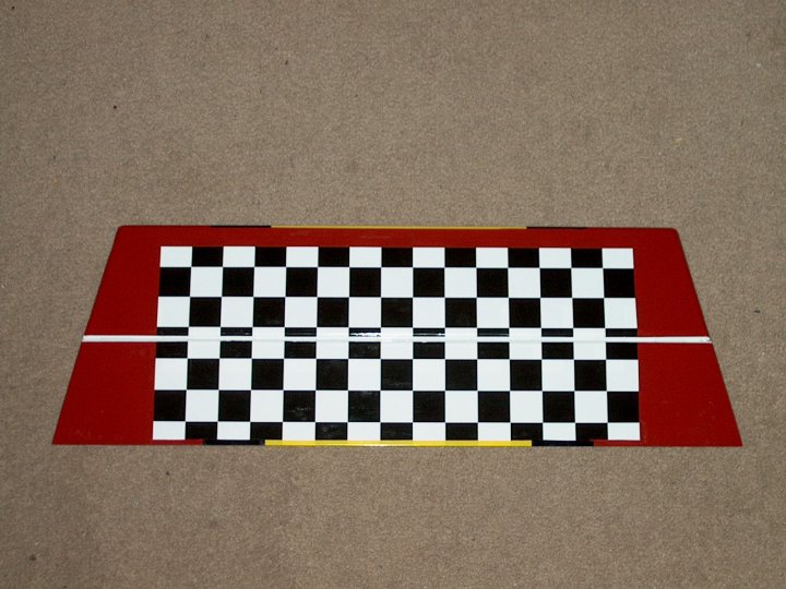
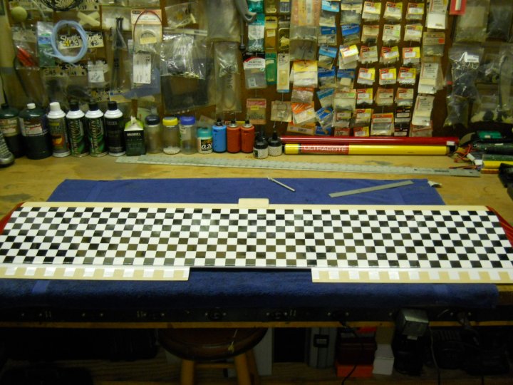
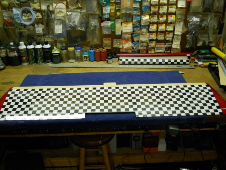
Skip asked to checkerboard the bottom, so we did just that
|
|
|
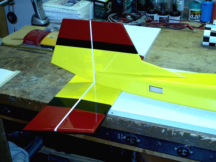
The Horizontal and Vertical surfaces were test fit on the fuselage...it looked good
|
|
|
Time to work on the Wing...Ailerons were cut to length and angled at the tips, then beveled and sanded
|
|
|
The entire wing was sanded to prepare for covering
|
|
|
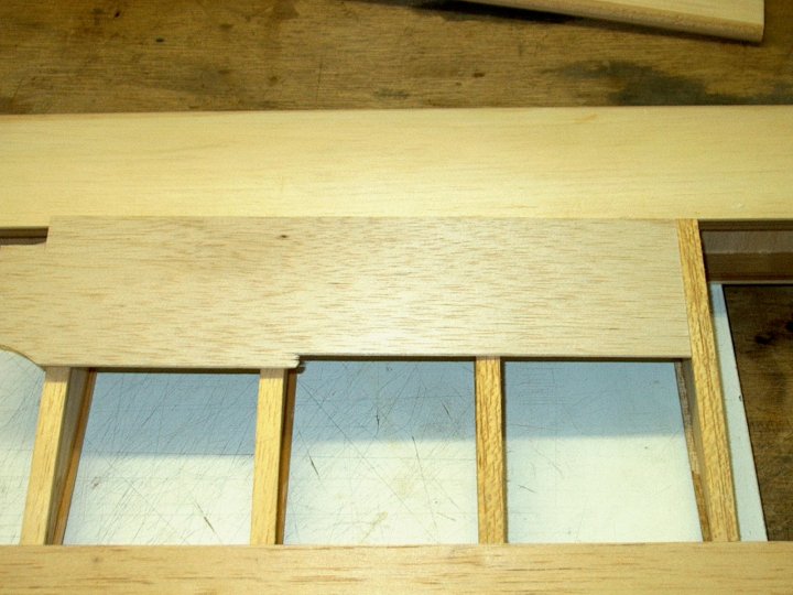
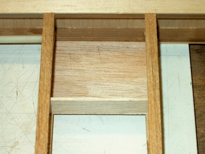
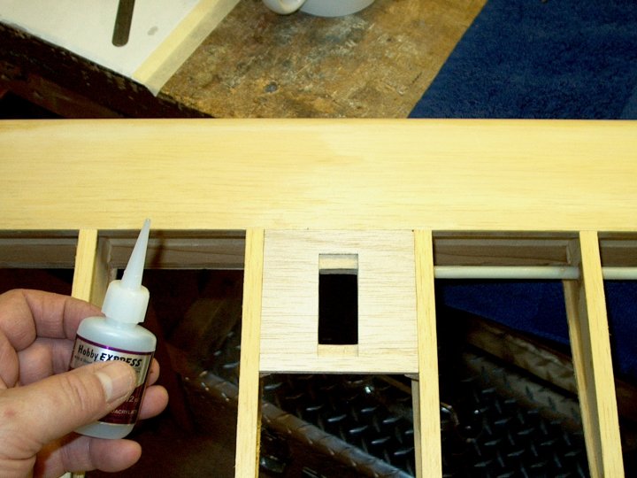
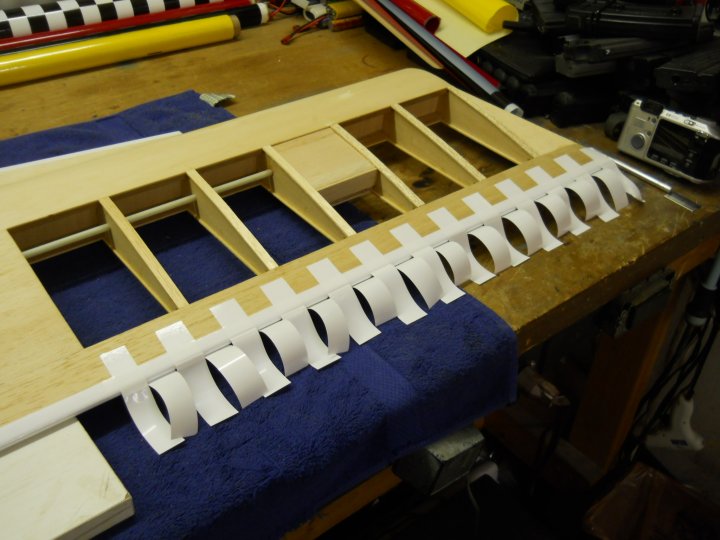
I decided to make new servo trays our of aircraft plywood to custom fit them to my servos. I cut out two plates, as
well as support triangle stock for underneath the plates and along each spar. I also cut a small basswood spar for
the front support agaist the main spar of the wing and I cut four hardwood blocks to add some thickness underneath the
plates for the servo screws to grip. The plates were fitted to each opening where they will reside
|
|
|
A piece of 3/32" balsa sheet was cut and fit to the top of the plywood servo plates to add some surface area for
the Monokote to adhere
|
|
|
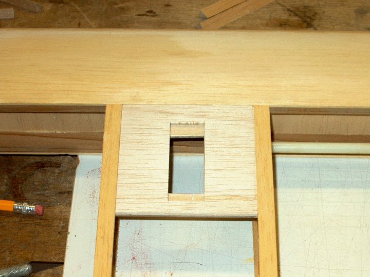
A servo was test fit into the opening to make sure we could get it in and out with ease
|
|
|
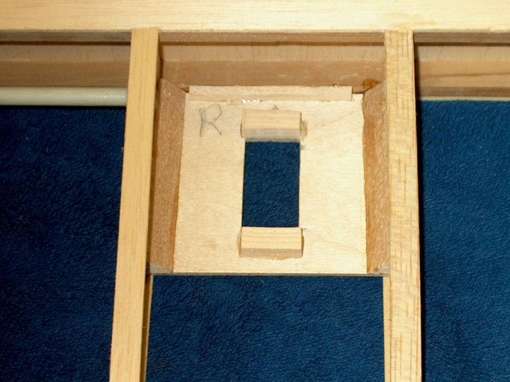
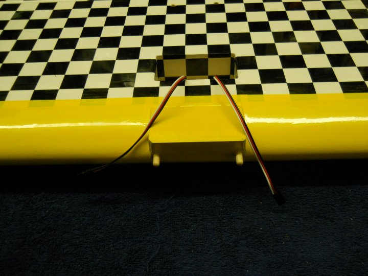
Something I have not noticed in pics of Skips's other G-Styks was an area inside the wing underneath the servo to
help hold the wires in place so they wouldn't be flopping around inside the wing area. I made a small "boxed-in"
area under the servo out of thin 1/16" balsa with a 3/32" end piece to complete the box; this area should hold the
wires and keep them from flopping around
|
|
|
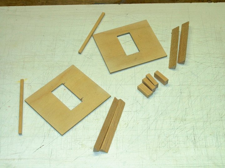
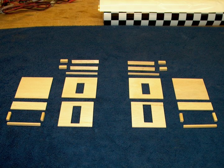
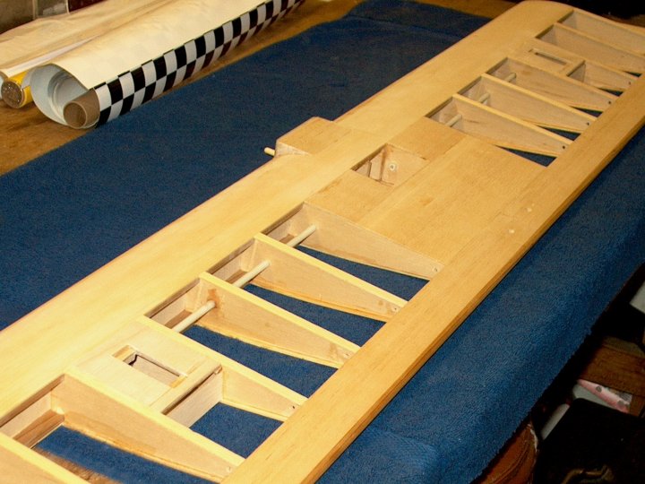
All of the Aileron Sero Tray parts were completed and shown ready to install
|
|
|
The 1/4" mount blocks were epoxied to the bottom of the trays to add more thickness for mounting screw grip
|
|
|
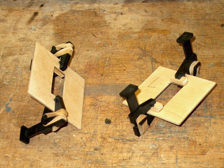
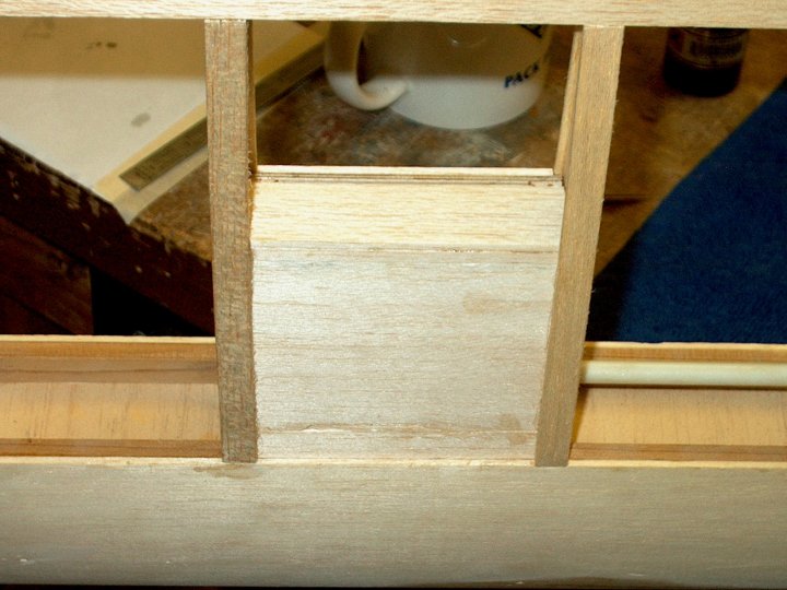
The Aileron trays were epoxied into place with triangle stock added for support and strength
|
|
|
The top piece of balsa was glued to the servo trays, then sanded flush
|
|
|
The bottom box for the wires was added to the other side of each wing
|
|
|
Aileron mounts shown completed and wing is ready for Aileron mounting
|
|
|
Monokote hinges were added to the rear of the wing and the Ailerons were attached to the wing with the hinges
|
|
|
I did not like the way the Ailerons looked, so I removed them, sanded them to shape and made new hinges, which were
installed on the wing. The left side Aileron is shown positioned for mounting
|
|
|
Hinges were applied to the right side and the Aileron was mounted. They are positioned so they are flush to the
bottom of the wing and are just slightly higher than the top of the wing
|
|
|
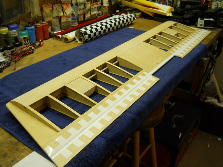
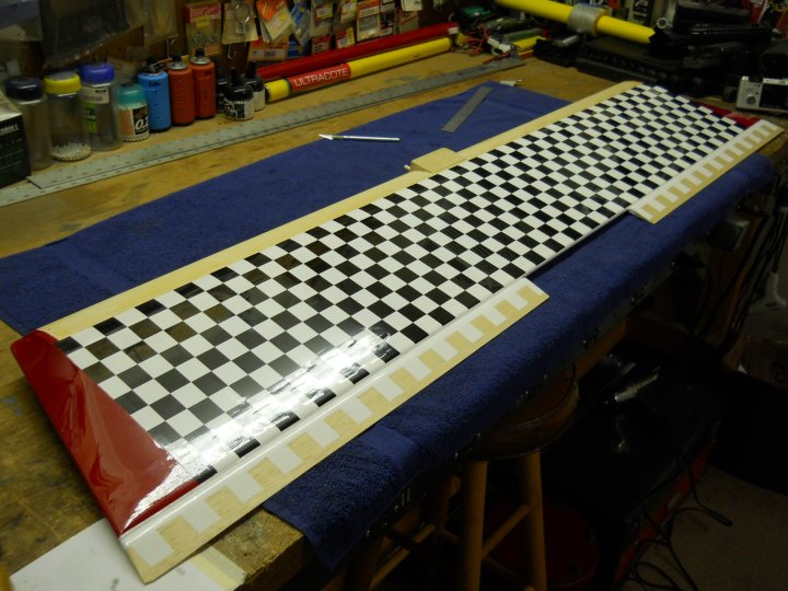
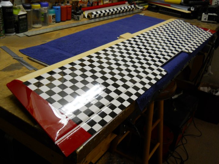
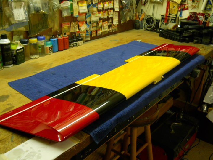
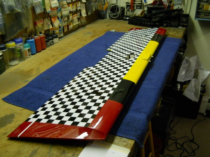
Time to cover! The bottom wing ends were capped with dark red Monokote, while the center section was covered with
checkerboard Monokote
|
|
|
Shown below are the dark red wing tips
|
|
|
The bottom of the Ailerons were aligned up with checkerboard Monokote and covered
|
|
|
Another view of the bottom of the wing covered and ready for top colors
|
|
|
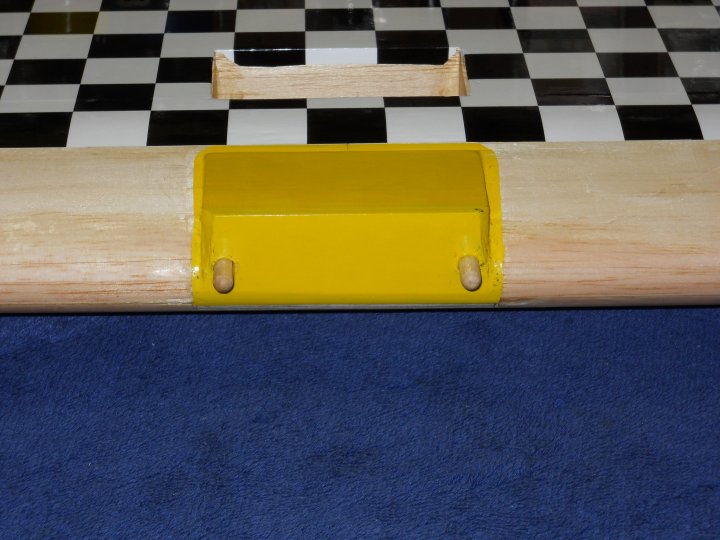
The center of the wing will be yellow, so I pre-Monokoted the mount area to make the top covering easier. Also shown
behind the yellow is the opening for the Aileron wires, which was opened up and finished
|
|
|
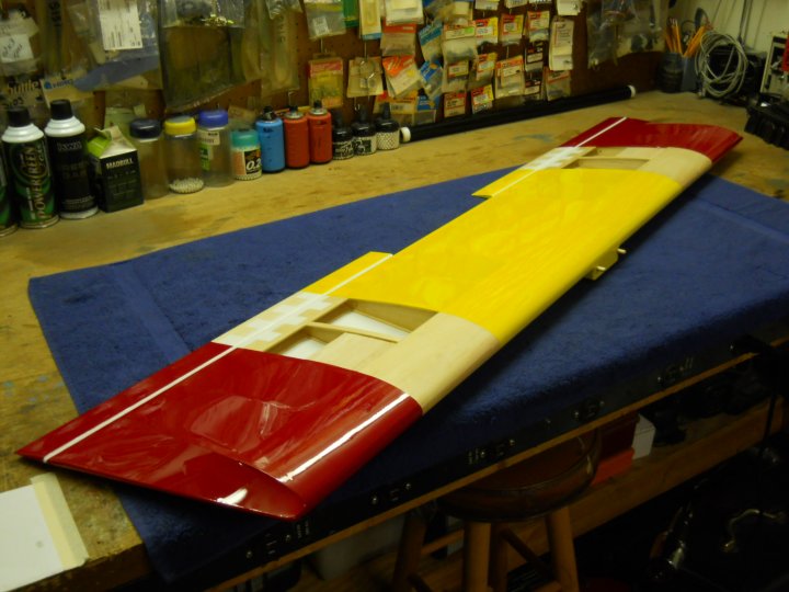
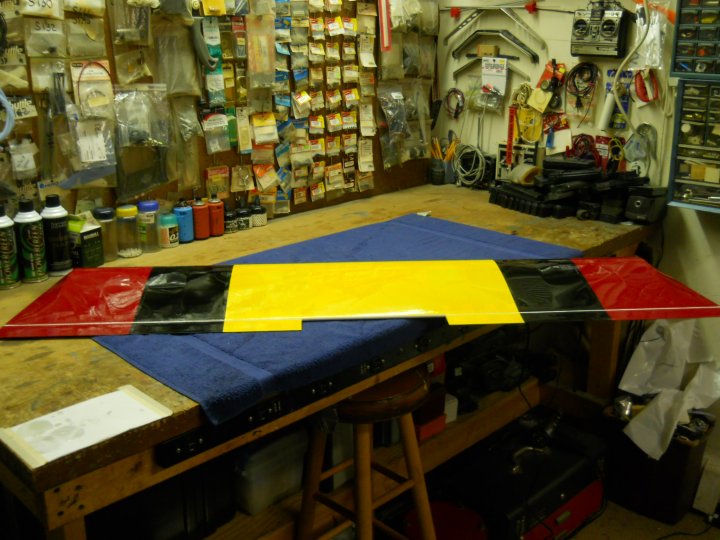
Red Monokote was added to the wing tips and outer panels, then yellow Monokote was added to the center
|
|
|
Finally, black Coverite was added for the stripes
|
|
|
Top view of the completed wing
|
|
|
Bottom view of the completed wing. Covering is now completed and it is time for the fun part...assembly
|
|
|
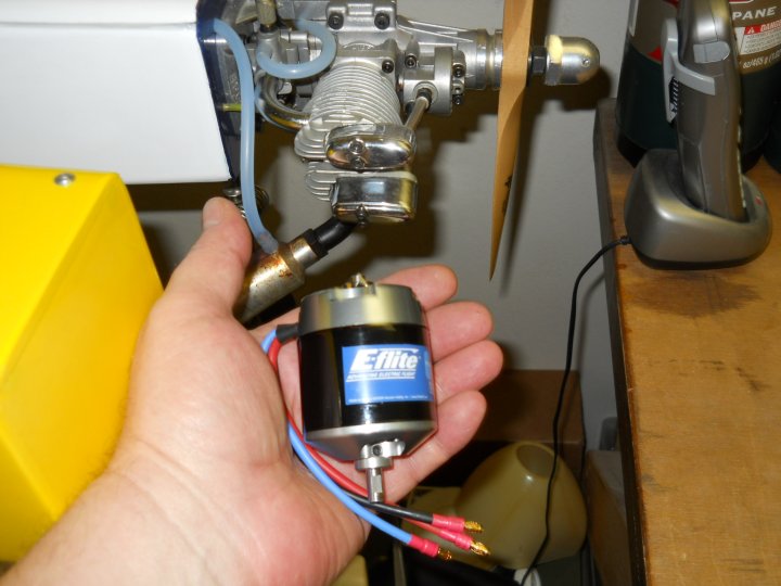
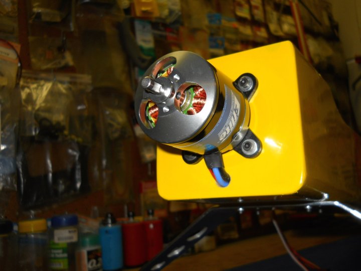
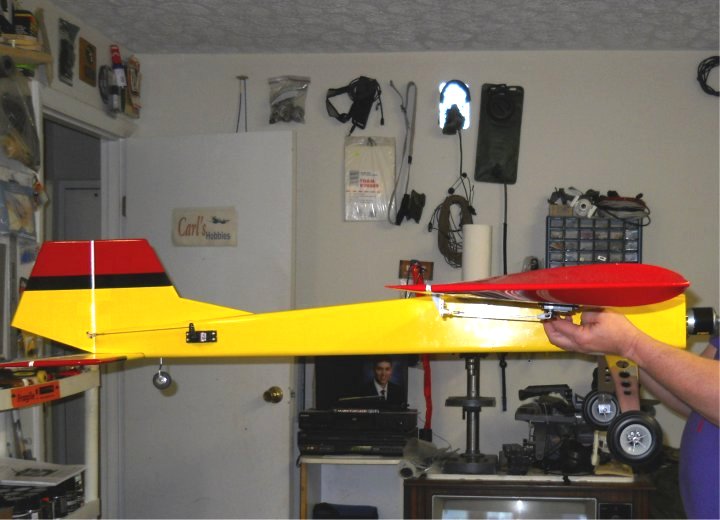
A quick view of the motor we will be using, an E-flite Power 60 Brushless Outrunner Motor. We held it up next to
our other G-Styk's Saito .91FS four stroke motor for size comparison. The electric motor is equal in power to a .61
two cycle motor and should work well in the airplane
|
|
|
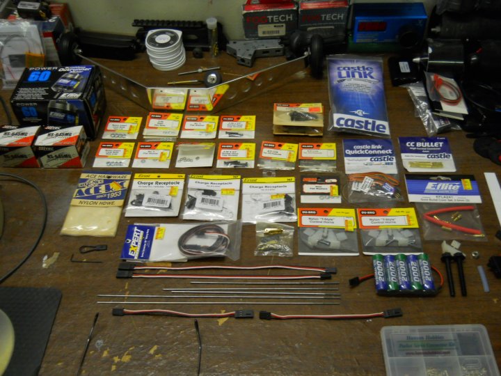
Parts are ready for installation
|
|
|
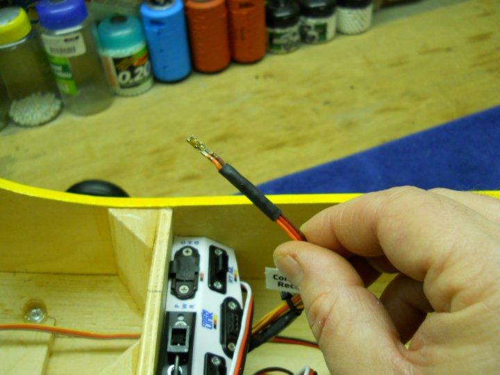
The exit wires for the wing were shortened and new plug ends were crimped on the ends. Also, the excess 10" of wire
that was trimmed off had new connectors crimped on and these will be used for wing servo jacks inside the fuselage
|
|
|
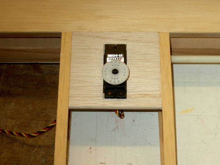
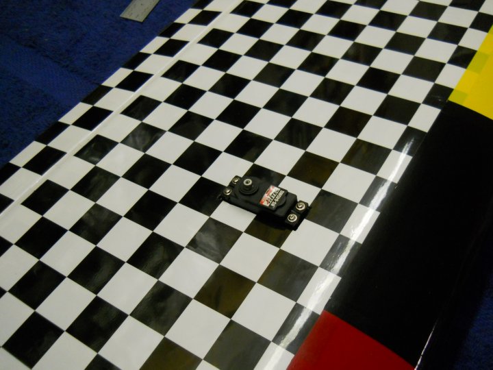
The servos were placed in each wing opening, then centered and holes were drilled. Servos were then assembled with
the supplied grommets and brass bushings, then plugged in to the extensions and mounted in each wing opening with the
supplied screws
|
|
|
A horn was placed on the Aileron for mounting. A piece of tape makes a good locator and helps it from sliding off
while checking position. The holes on the horn should be located right above the joint where the wing and Aileron meet
|
|
|
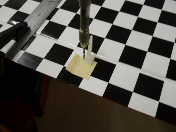
A hand drill was used to drill the mount holes for the control horns
|
|
|
The pushrod was assembled with a clevis and lock nut, then positioned so its length could be cut. I made a mark on the
rod at the servo horn, then bent a 90 degree angle in the rod end and cut it to length
|
|
|
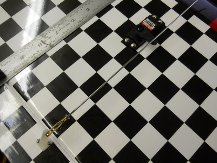
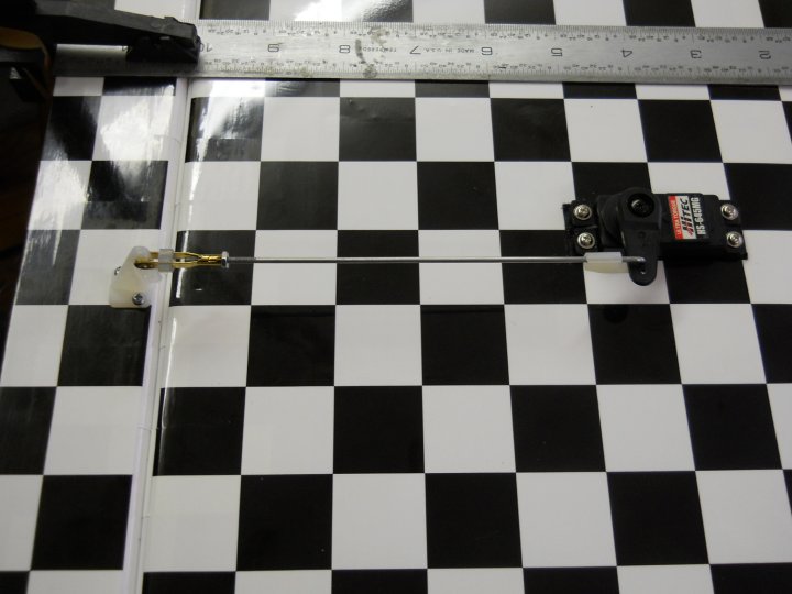
The pushrod is shown assembled, with an E/Z Link at the servo end and a small piece of fuel tubing is used as a clevis
retainer. The servo was centered with a servo tester, then the clevis was adjusted for the correct length before
assembly and the nut was tightened to keep it in place
|
|
|
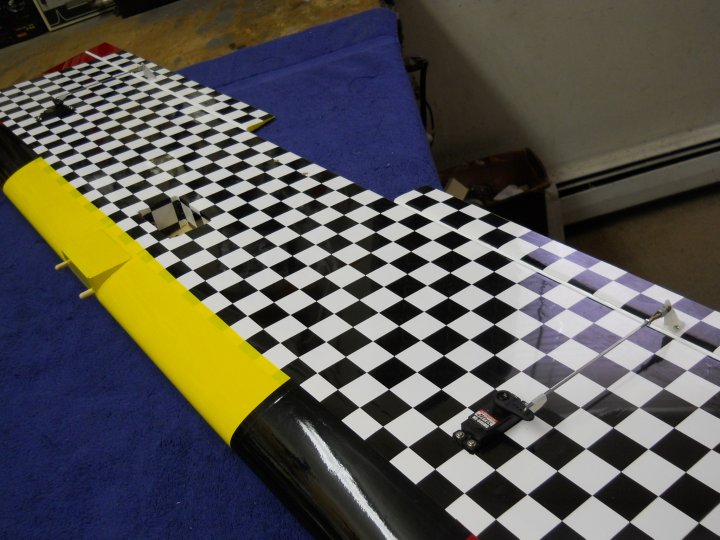
Both servos and cotrol rods/clevis' were installed in the same manner. This completed the wing assembly
|
|
|
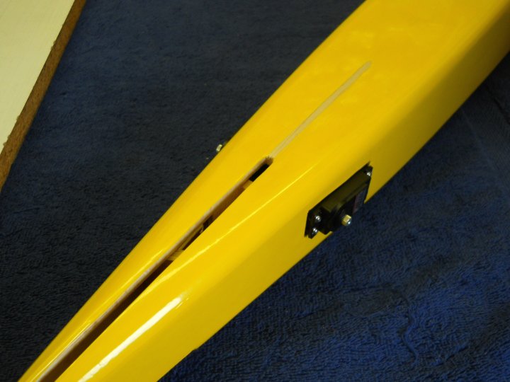
The Elevator and Rudder servos were installed
|
|
|
The Monokote at the center of the horizontal stab and on the fuselage for the vertical stab stake was cut away for
epoxy to adhere
|
|
|
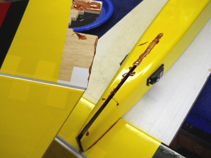
Epoxy was applied to the rear tail assembly and then joined. A good quality 15 minute epoxy is recommended in order
to give you time to assemble the tail. I prefer West Systems Epoxy, as it soaks into the wood well and creates a
very strong bond
|
|
|
The excess epoxy was cleaned up with paper towels and Alcohol and the assembly was clamped and left to set
|
|
|
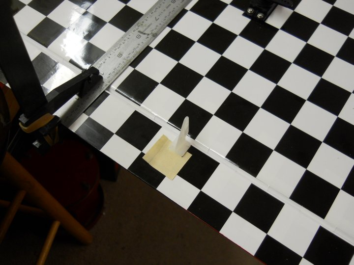
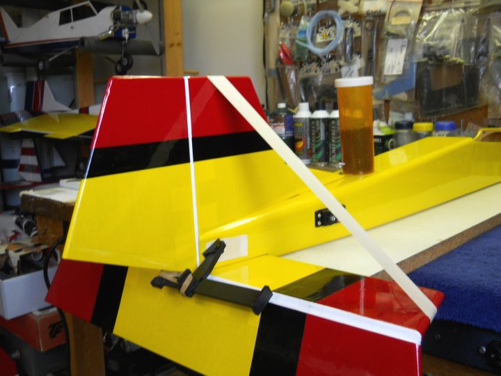
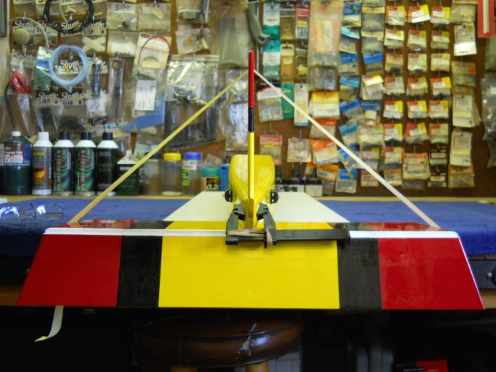
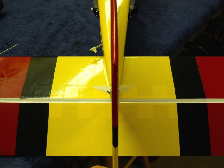
You need to make sure the vertical stab is perpendicular to the horizontal stab, as shown in the view
|
|
|
The main landing gear was mounted on the fuselage
|
|
|
LokTite was applied to the wheel collar and the tailwheel was installed
|
|
|
Tailwheel installation completed
|
|
|
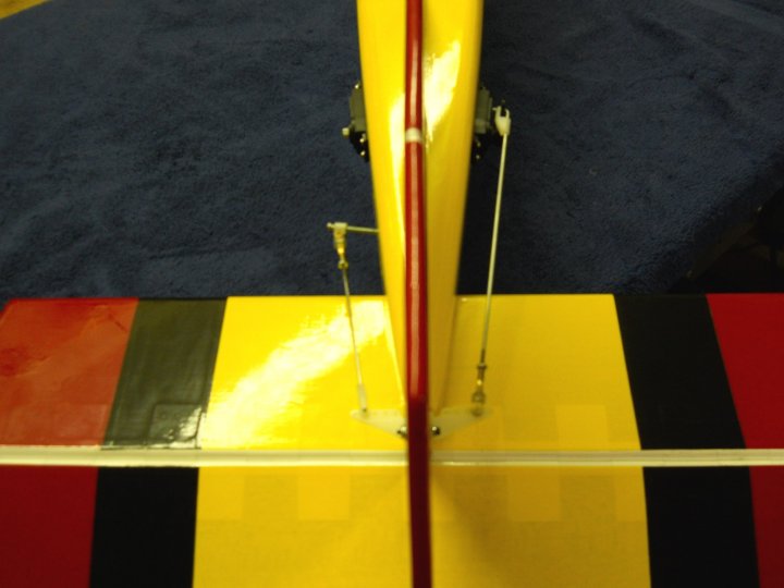
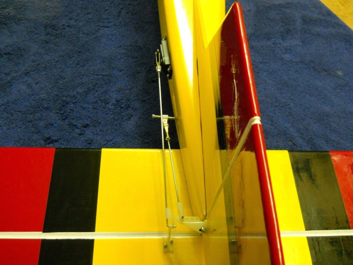
A dual clevis setup was installed on the rudder
|
|
|
The clevis' were bolted together
|
|
|
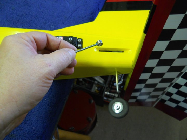
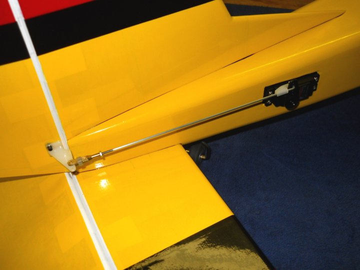
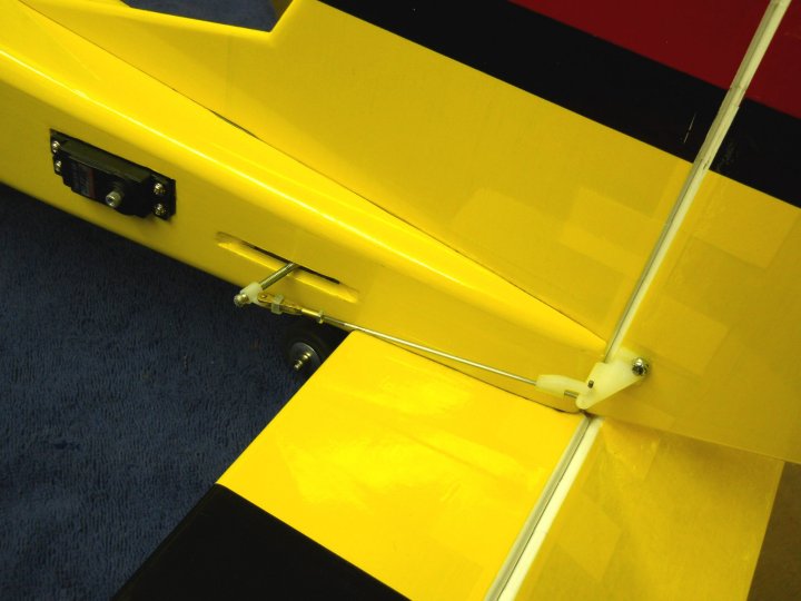
The rudder pushrod was installed
|
|
|
A tailwheel steering pushrod was installed from the second clevis to the control rod
|
|
|
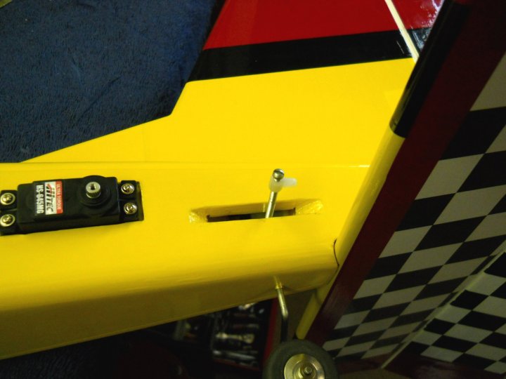
The rudder assembly is shown completed
|
|
|
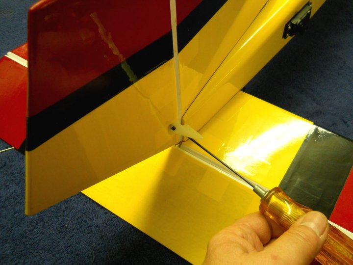
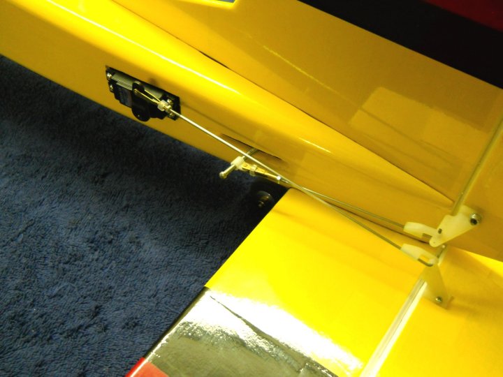
The elevator horn was installed and pushrod was cut to length and connected
|
|
|
The elevator pushrod has plenty of clearance from the steering rod and neither of them bind during maximum deflection
in both directions
|
|
|
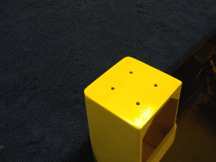
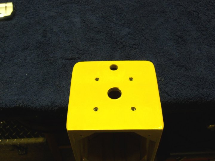
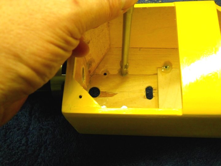
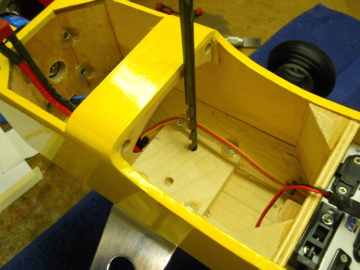
Four holes were drilled for the motor mount
|
|
|
The balsa triangle was cut away to make room for the motor mount blind nuts
|
|
|
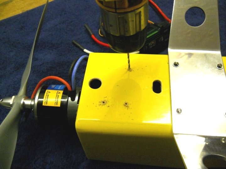
A center starter hole was drilled for the motor rear bearing clearance
|
|
|
A larger hole was made with a forstner bit
|
|
|
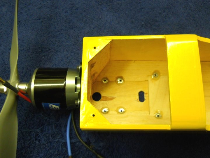
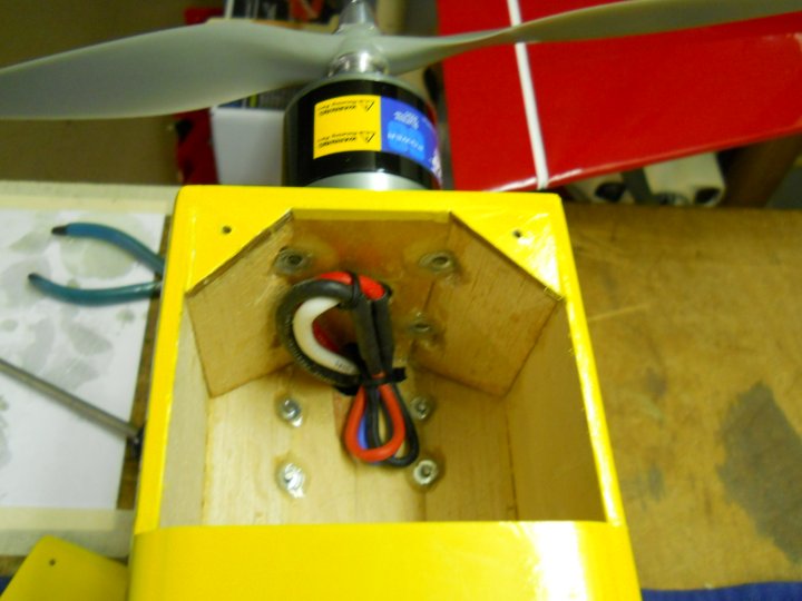
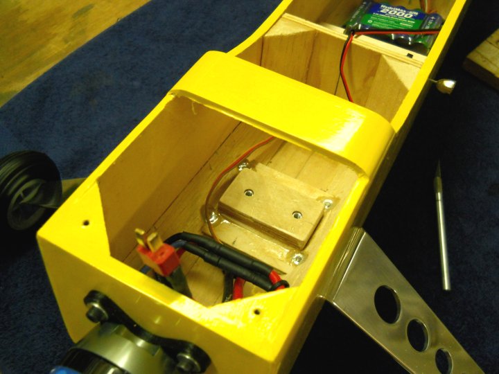
The blind nuts supplied with the motor were installed and epoxy was applied to keep them from pushing out
|
|
|
A lower hole was drilled for the motor wires
|
|
|
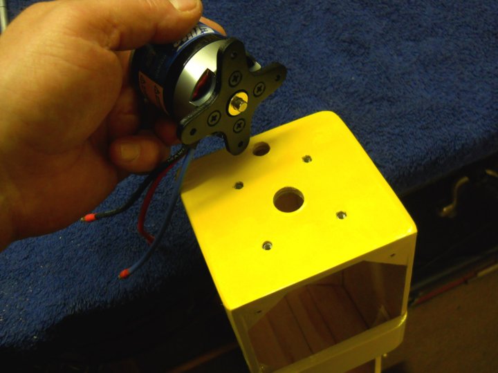
The motor mount was installed on the motor using some LokTite
|
|
|
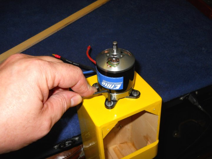
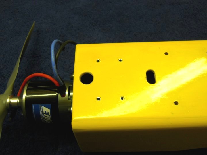
The motor was mounted using the supplied bolts
|
|
|
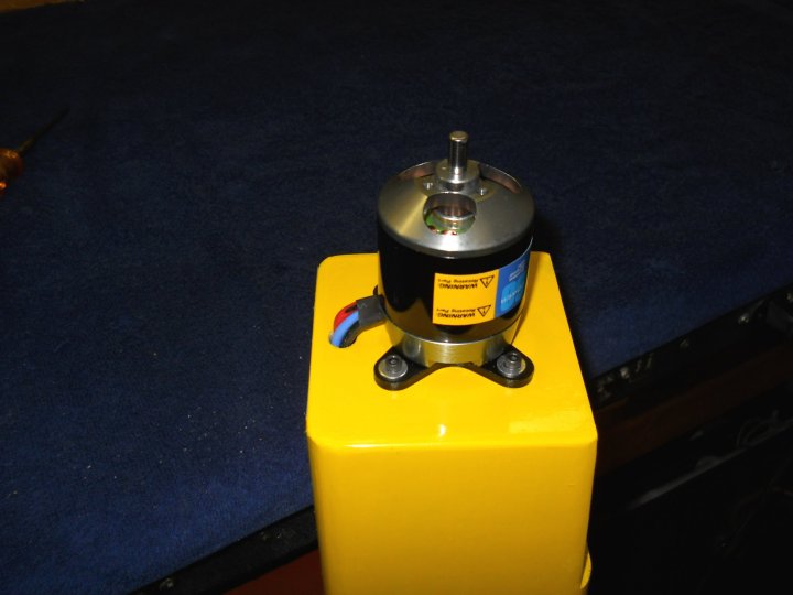
Motor wires were run through the lower hole into the fuselage area
|
|
|
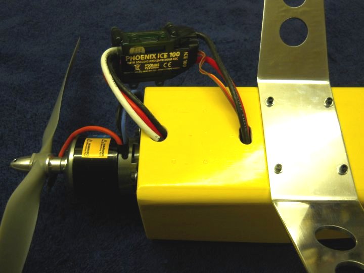
Motor is shown mounted and ready to go
|
|
|
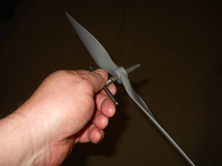
The propeller was reamed out to fit the propeller shaft
|
|
|
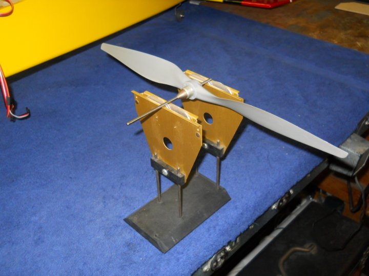
The propeller was balanced and ready to install
|
|
|
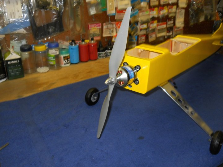
The propeller was installed on the motor using the supplied hub that came with the motor
|
|
|
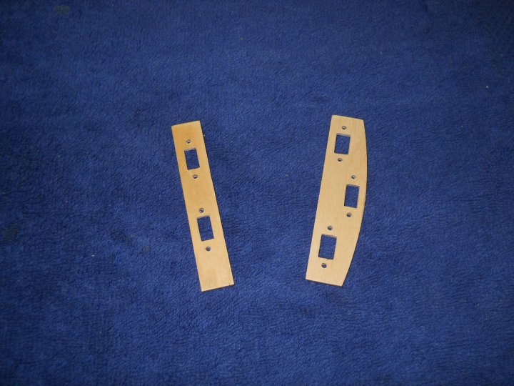
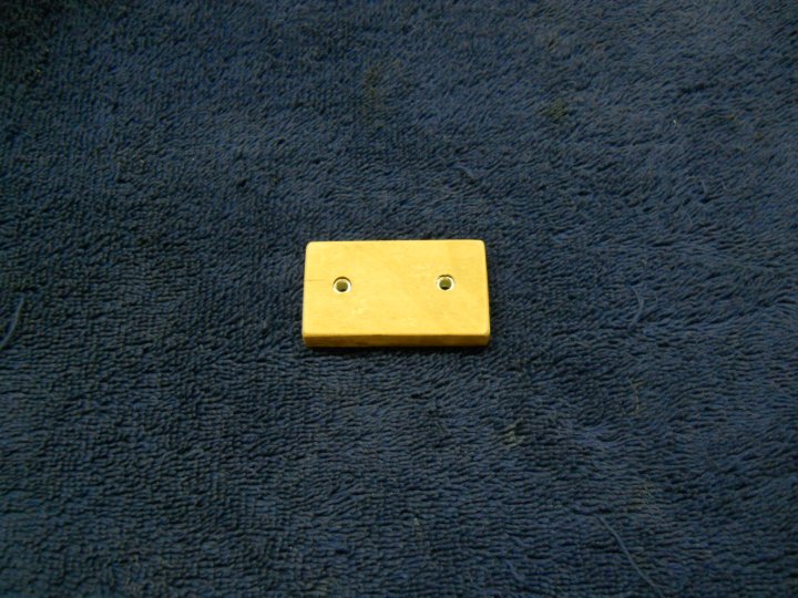
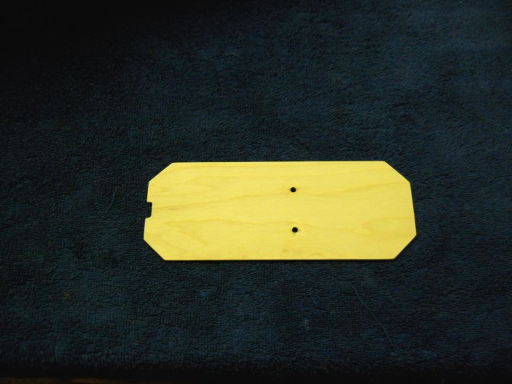
The afternoon was spent designing the interior. A set of control panels were made from 1/8" aircraft plywood
|
|
|
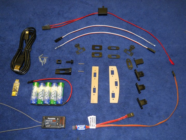
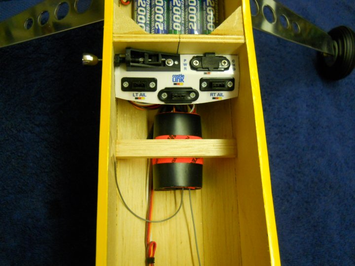
The electronics that remain to install into the airplane are shown
|
|
|
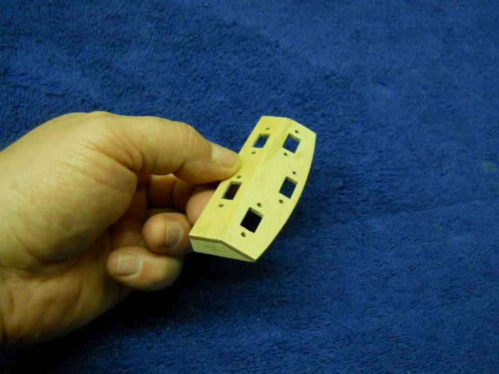
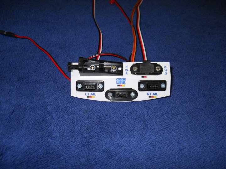
The control panel was assembled with side supports
|
|
|
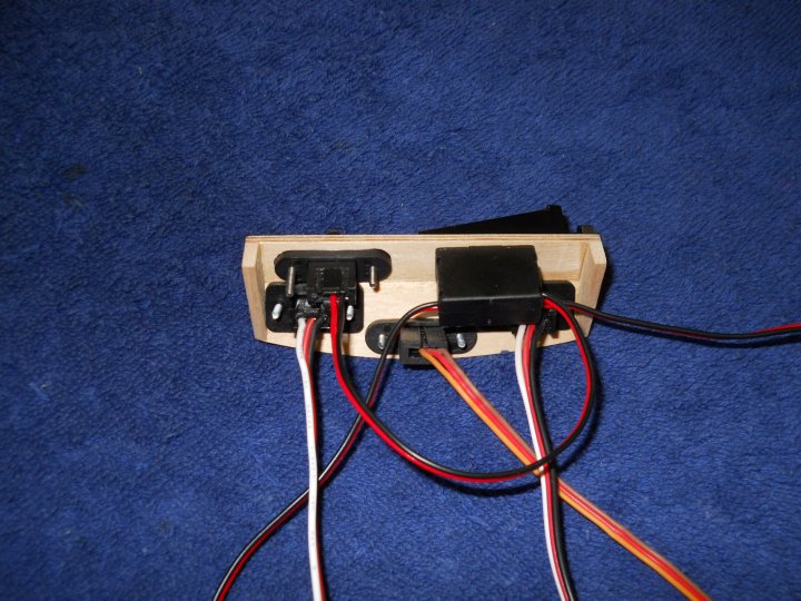
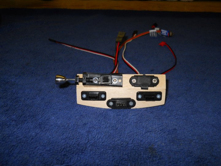
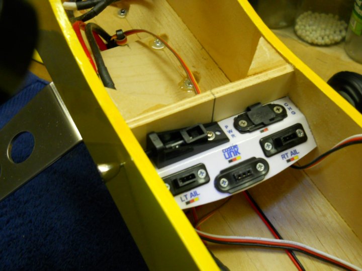
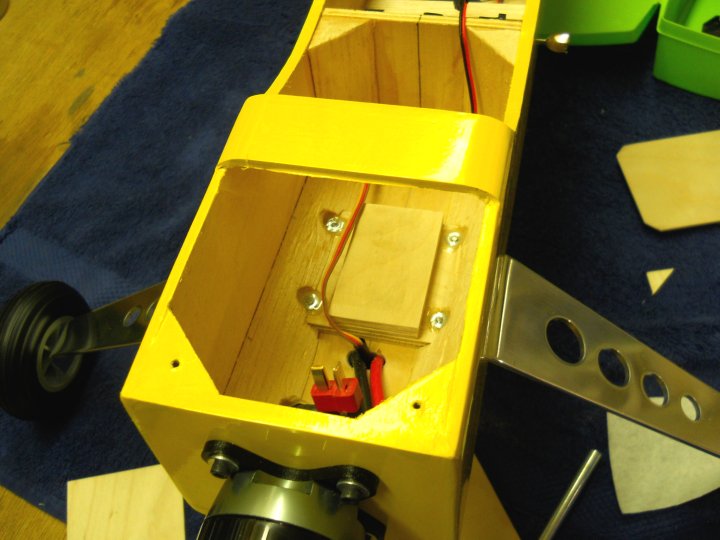
The electronic components were installed in the control panel. This is a rear view of the wiring
|
|
|
A view of the control panel front, ready to install in the fuselage
|
|
|
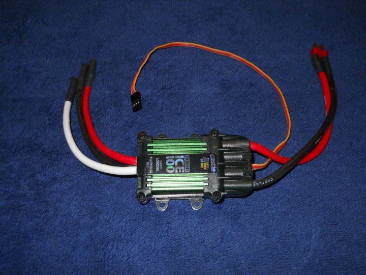
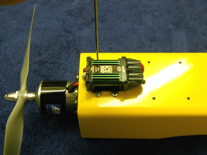
The ESC arrived, a Castle Creations ICE 100 rated at 8S Lipos and 100 amps. Castle Creations 4mm Bullet Connectors
were soldered on the three motor wires and a Deans Ultra Male Connector was soldered on the power wires
|
|
|
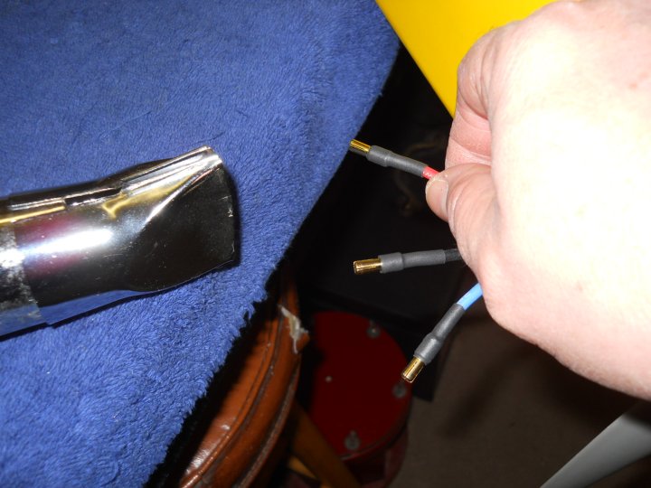
The 4MM plugs were soldered on the motor and covered with heat shrink. You always want to solder the plugs on the
non-powered side and sockets on the side where power exits for safety
|
|
|
I decided to mount the ESC externally rather than internally for better airflow cooling. This comes from a decade
of experience with high performance EDF Jets and you find airflow is key to keeping your ESC in good condition. Two
holes were drilled on the bottom of the fuselage for the wires to pass through
Let's see if Skip is paying attention to the landing gear in this photo |
|
|
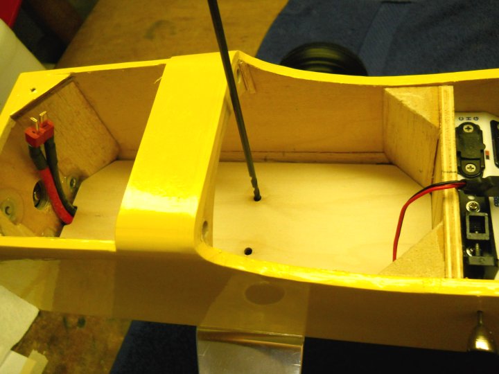
Four holes for ESC mounting were marked and drilled with a starter bit, then opened up for 4-40 blind nuts
If Skip was paying attention to the landing gear, he would see the difference in this view and know I was messing with him ;o) |
|
|
4-40 blind nuts were installed for the ESC mount
|
|
|
Epoxy was applied to the edges of the blind nuts to hold them in place during installation and prevent them from pushing
out
|
|
|
The ESC mount is shown completed
|
|
|
The ESC was installed in its location with 4-40 bolts, lock washers and flat washers
|
|
|
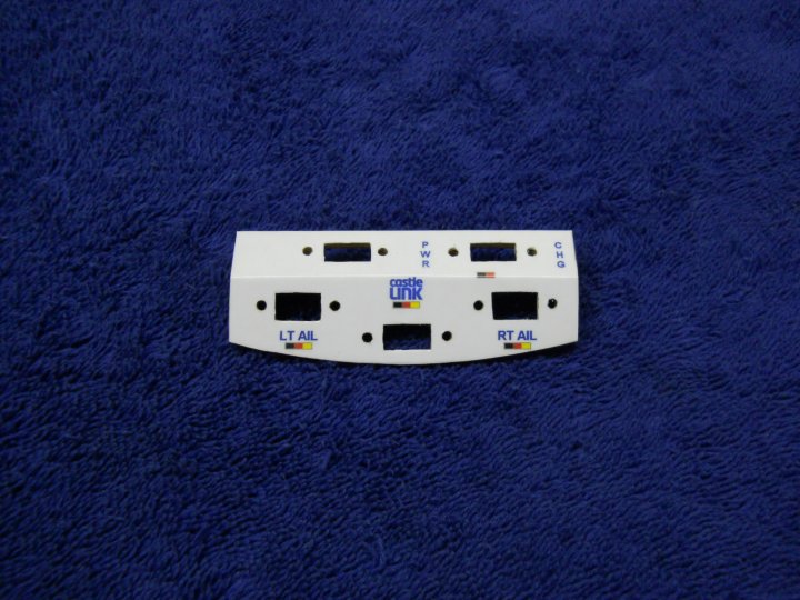
A label identifying the control panel was designed and printed on Avery full sheet label paper, then covered with
a plastic top using heavy duty clear packing tape to help prevent fading and promote better wear. It was positioned
and installed on the panel, then the holes were cut out for the jacks and switch
|
|
|
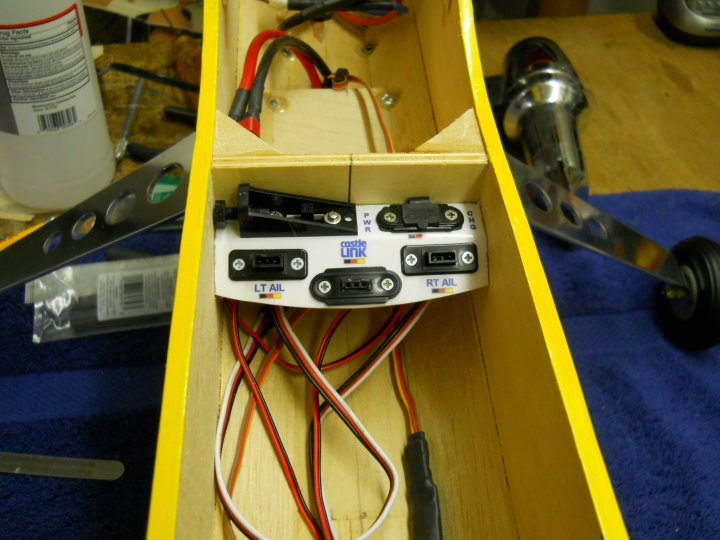
The Control Panel was assembled and is ready for some epoxy and permanent installation in the fuselage
|
|
|
The Control Panel was epoxied in place inside the rear of the fuselage
|
|
|
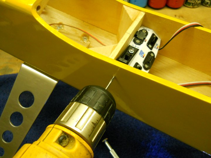
A mark was made by eye for the On-Off switch and drilled for the switch rod
|
|
|
The external switch knob and rod were installed
|
|
|
A hole was drilled at the bottom right side and rounded along the edges so it would not cut into the wire. The
ESC wires were disassembled from the connector, then passed through the hole and plugged back in to the connector
|
|
|
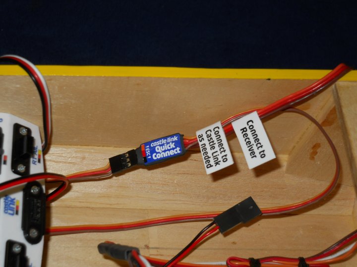
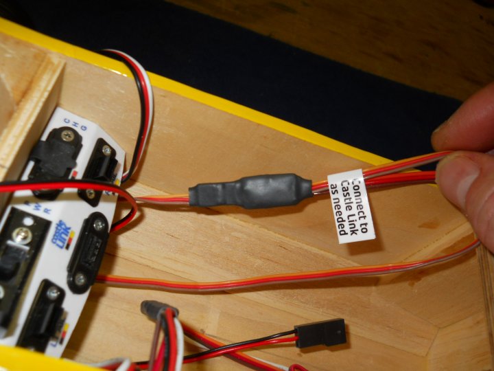
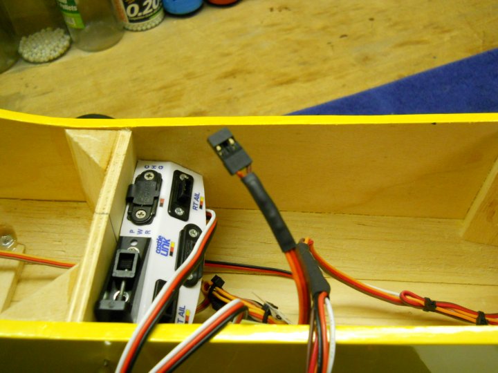
The ESC wire is plugged into the Castle Creations "Quick Connect". This device has two output wires, one that goes
to the receiver and one that goes to the socket for the Quick Link cable that is connected to your PC. It allows
programming of the ESC with your PC without having to unplug the ESC from the receiver and it is auto-sensing and
knows when the programming cable is plugged in for configuration
|
|
|
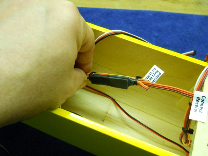
A piece of heat shrink is installed over the Quick Connect and ESC plug to hold the plug in place and prevent it from
comming undone
|
|
|
The excess wires were dressed and tie wrapped
|
|
|
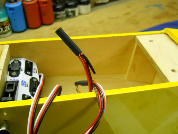
The Power wire on the receiver ESC end must be removed if using a seperate receiver battery. This prevents damage
to the ESC, which can occur when using an external battery source, as it has an onboard BEC(battery eliminator circuitry)and
can also can supply power to the receiver
|
|
|
The positive power wire is bent away from the plug and heat shrink was applied to prevent shorting and damage
|
|
|
Heat shrink is used to hold the positive control wire out of the way
|
|
|
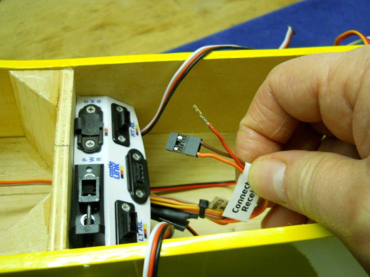
The ESC receiver connector is re-installed on the wire set
|
|
|
The receiver is hooked up to all of the connectors and tested. The test was successful
|
|
|
The receiver was wrapped in foam. Not much is needed because there is little to no vibration in the airframe
|
|
|
The receiver was installed with a piece of double stick tape to hold it in place. A 1/2" wide balsa stick is used to
apply some down pressure to keep the receiver from breaking loose and moving aorund
|
|
|
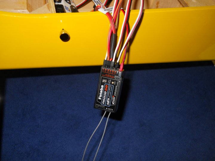
The antennas were routed at 90 degrees from eachother for maximum coverage. A small 1/16" hole was drilled at the rear to
allow the antenna to remain straight, while the other antenna was taped vertically to the side wall
|
|
|
Wires for the motor and ESC were dressed up and wire wrapped out of the way
|
|
|
Initial tests showed approximately 900 watts of power with an old, unmatch and lower power battery setup
|
|
|
Wing bolts were cut and installed to check balance, which is 1 - 1 1/2" rear of the main spar
|
|
|
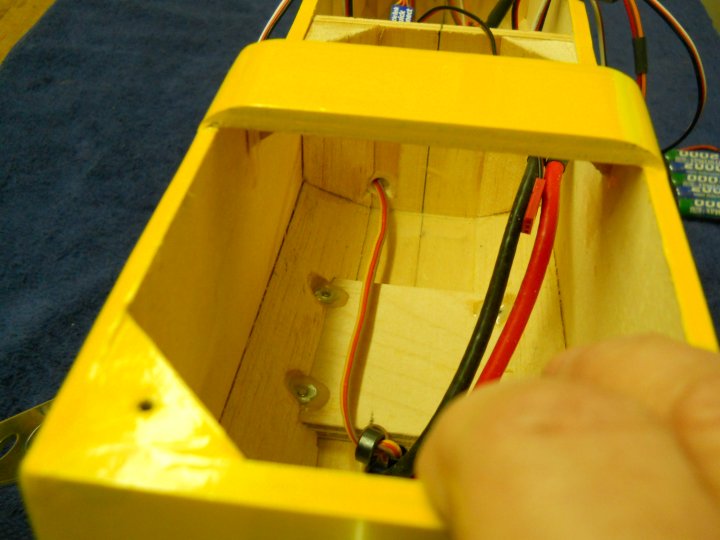
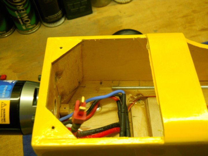
A 1/4" hole was drilled at the bottom left side of the center bulkhead and the power wires from the switch were run
through the hole. The receiver battery will be located at the front of the fuselage to help with balancing the airplane
|
|
|
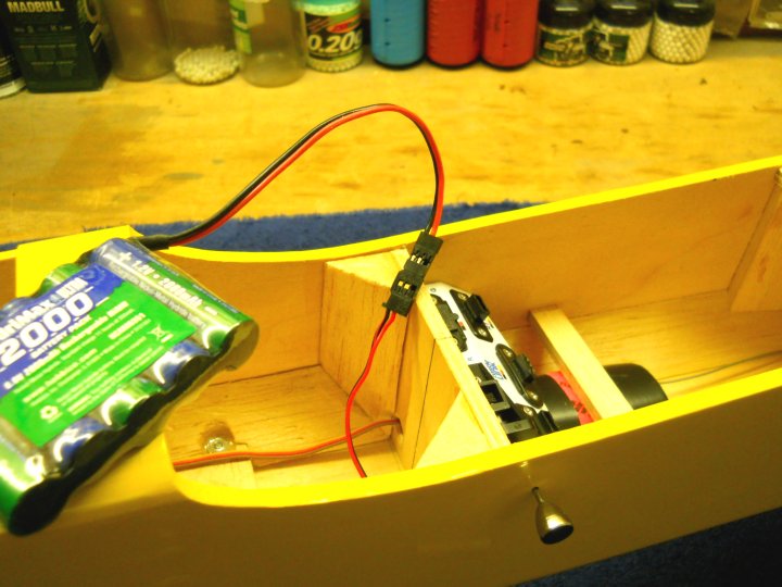
The battery is shown plugged into the switch plug. A connector sleeve was installed after this pic was taken to hold
them together better and prevent the pins from bending
|
|
|
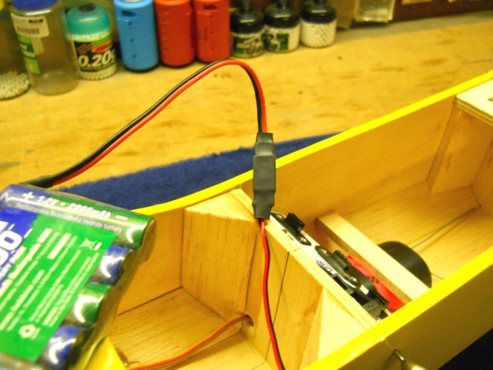
Heat shrink was applied to hold the power connectors for the receiver battery together and prevent them from pulling apart
|
|
|
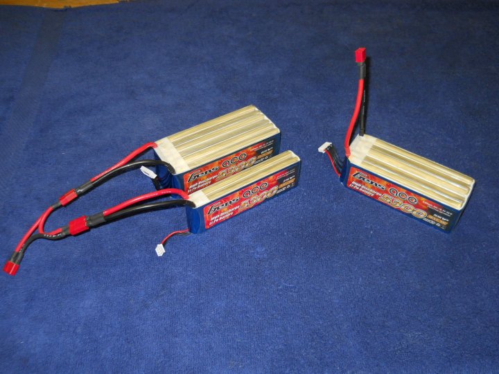
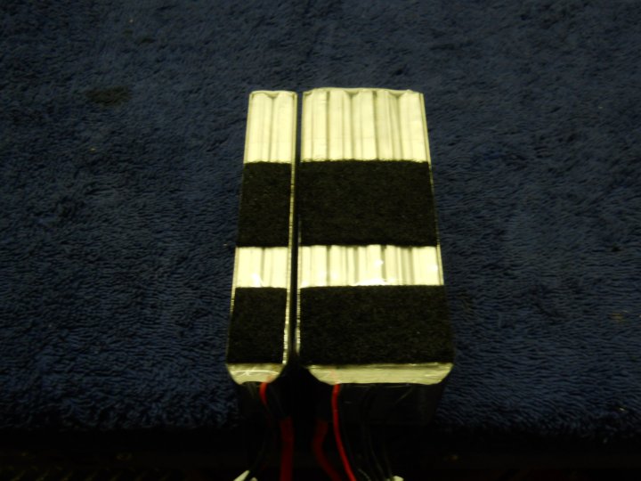
The new batteries arrived...Gens Ace 5300mah 30C Lipos rated at 159 amps continous draw. One is a 6S battery, while
the other is a 5S and 2S hooked in series to make a 7S battery, which is the maximum rating for the motor. I removed
the 4mm barrel power plugs and installed Deans Ultra Connectors, as these are what I use for all of my airplanes.
Both batteries will be tested in the model
|
|
|
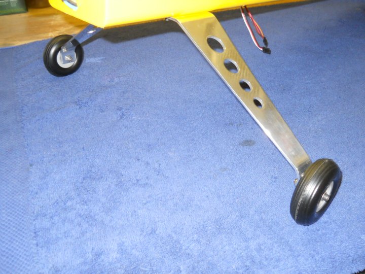
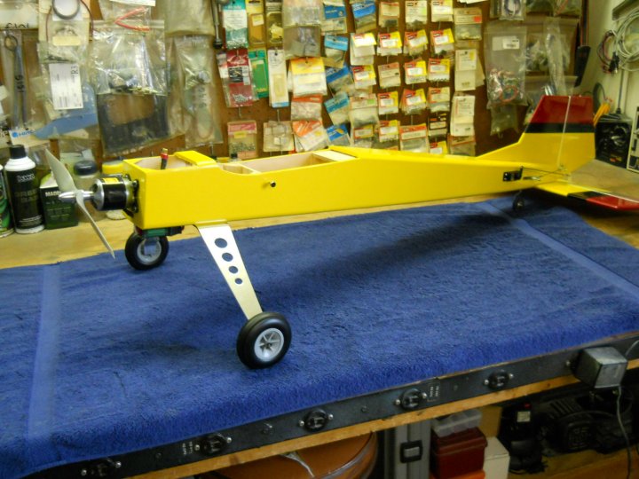
I purchased some 3 1/2" wheels for the G-Styk, as the small 2 3/4" just looked to tiny and the larger wheels per Skip
give some additional ground clearance in case of hard landings, which was something I had not considered. They were
mounted and actually look to be a pretty good fit for the model
|
|
|
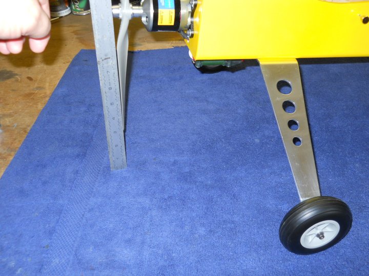
The propeller has nearly 3" of clearance now when the aircraft is at rest
|
|
|
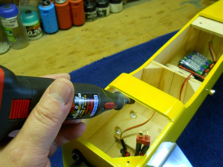
The fuselage top had a sharp edge that I didn't like, as it was rubbing on the batteries during installation. I used
a Dremel to slightly round the bottom forward edge
|
|
|
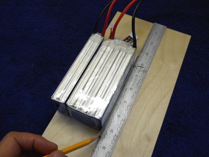
The batteries were set on a piece of 3/32" aircraft ply flush to one side and a mark was made to see how wide the
wood needs to be to support the pack
|
|
|
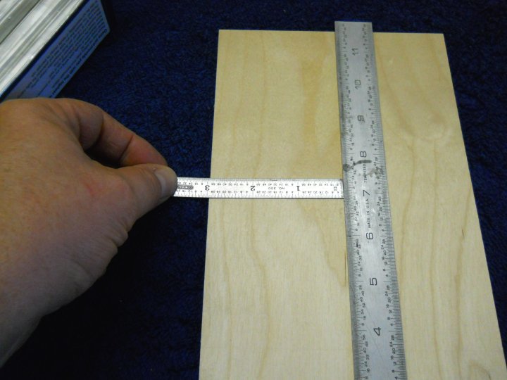
The required width turned out to be 3" for the pack
|
|
|
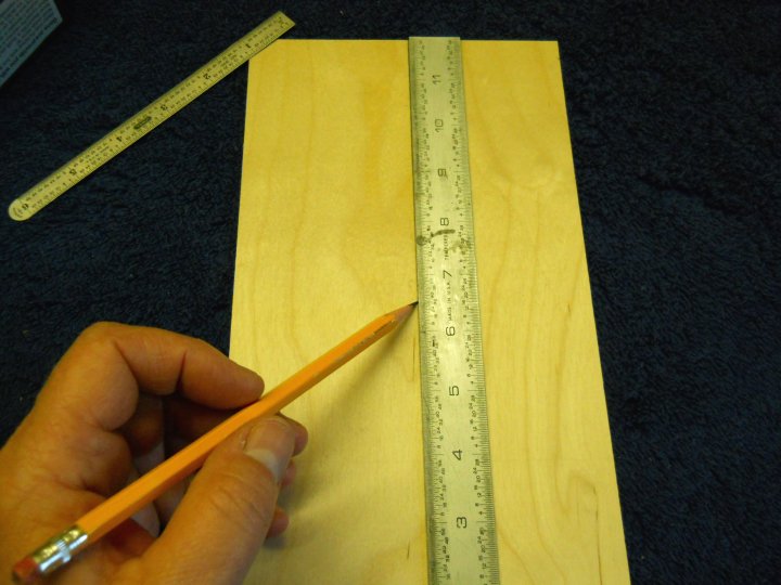
The ply was marked at 3" wide and cut the entire length of the sheet
|
|
|
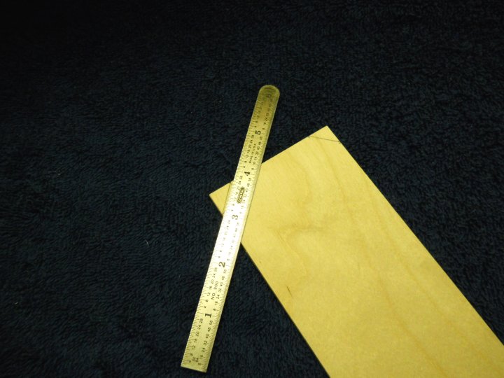
The front and rear ends were cut to fit the fuselage
|
|
|
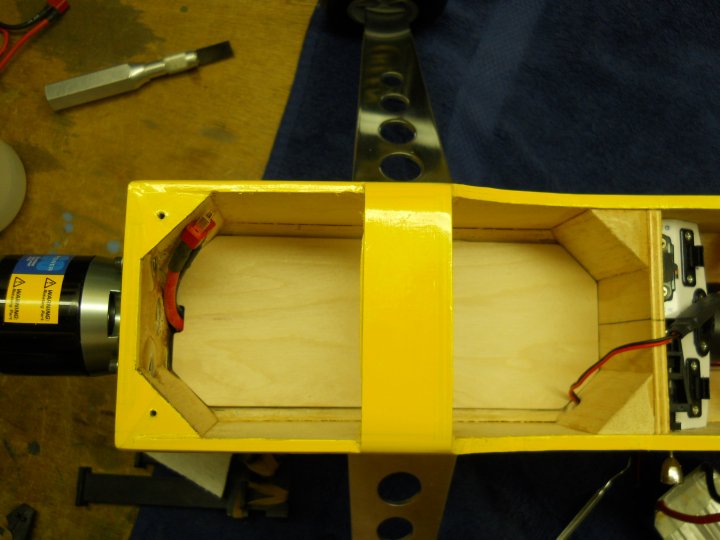
The tray was inserted and checked for fit. It should be a good fit but not snug, in case it needs to be removed
later. Note that the tray sits high enough to hide the motor and ESC wires, as the edges are held up by
the fuselage triangle stock
|
|
|
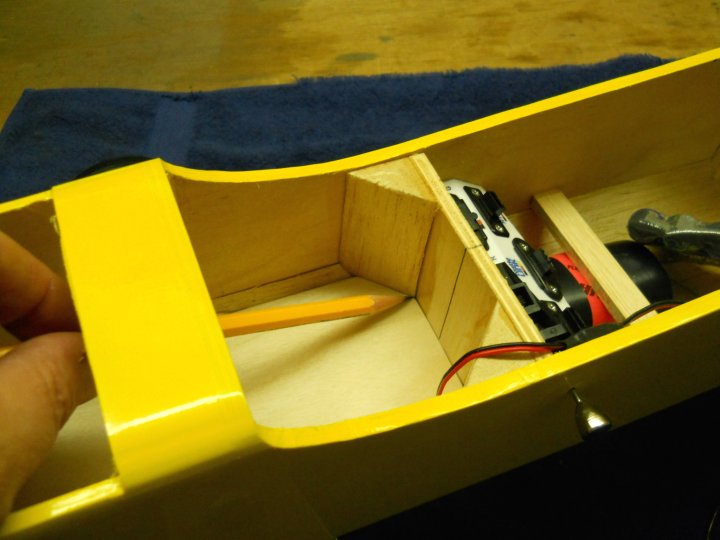
A pencil mark was made across the back and front for marking the height
|
|
|
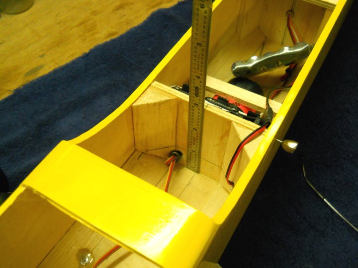
The height was measured and the height of the mounting block needs to be 3/32" shorter to compensate for the tray
thickness
|
|
|
A block was cut from hardwood and built up to height, then epoxied in place. The rear of the tray will be screwed to
this block
|
|
|
A block of ply was made for center support of the tray and the tray was fit to insure it was thick enough
|
|
|
The plate was positioned sideways and the tray was installed, then a drill was used to mark initial holes through
the tray and into the plate. You can tape the plate in place, but this one stayed in place between the epoxy fillets
that were on the landing gear screws
|
|
|
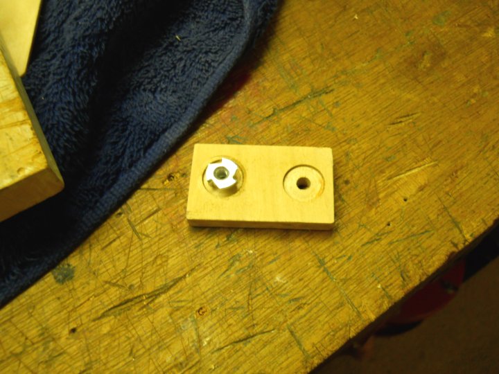
The holes in the plate were enlarged to fit 8-32 blind nuts and then countersunk with a forstner bit. Tape disks
were placed on the holes to prevent epoxy from leaking into the threads
|
|
|
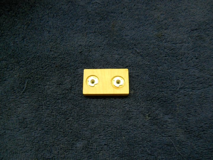
Blind nuts were installed a little deeper than the bottom
|
|
|
A view of the top of the block, which was coated in thin CA and sanded smooth to add strength
|
|
|
The tray holes were enlarged to fit the 8-32 bolts
|
|
|
1/4" holes were made about half the depth of the plate to allow the bolts to pass slightly into the landing gear block
|
|
|
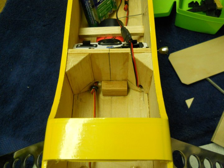
The center block was epoxied in place with fillets of epoxy made around the edges
|
|
|
Two mounting blocks were cut to a length of the height of the drawn line/tray height minus 3/32" to account for the
thickness of the battery tray
|

|
|
The blocks were epoxied in place. A little wood had to be taken off the corners to clear the glue around the blind
nuts in the firewall and this allowed the blocks to sit flush with the firewall for good glue purchase
|

|
|
Two #4 holes were drilled using a small hand drill. The holes were drilled through the plate and into the top center
of each mounting block. Center was easy to locate, as you could still see a little of the blocks between the tray
and firewall
|

|
|
A #6 center hole was drilled at the rear of the tray for a screw mount. All tray holes were opened up so the screws
pass through easily
|

|
|
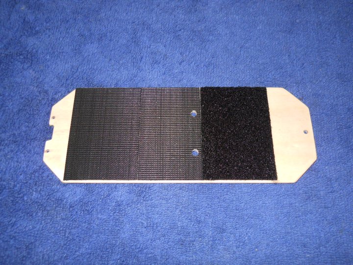
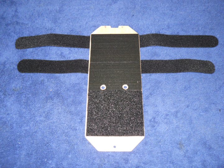
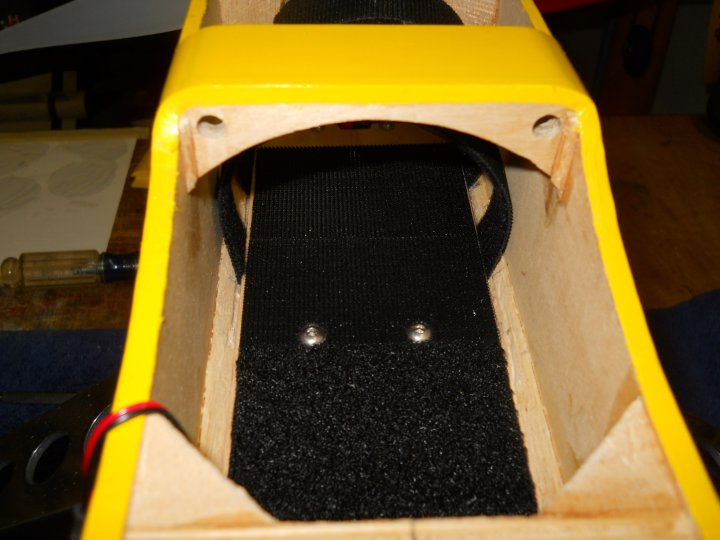
The tray was "glazed with a few coats of thin CA, then sanded to a smooth, plastic finish. This was done so the
Velcro can stick well to the tray, as it does not adhere well to porous wood
|

|
|
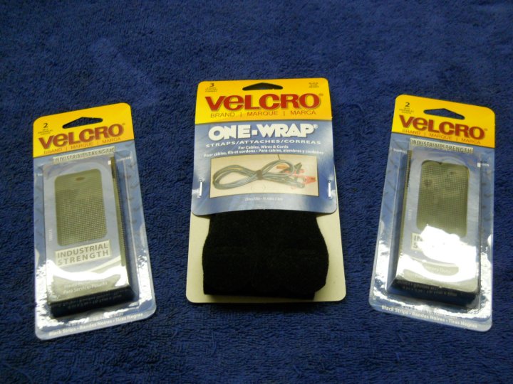
Industrial hold stick back Velcro will be used for battery mounting, while the Velcro straps will be used to hold
the batteries in place. These were purchased at Home Depot
|
|
|
Velcro was applied to the battery tray with padding to the rear to soften the tray for the batteries, allow for
easier installation and help pad the receiver battery. Also, the holes for the center mount bolts were opened up
with an Exacto knife
|
|
|
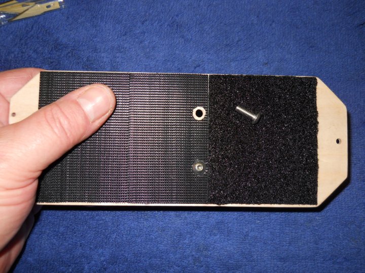
Bolt holes were trimmed away so the bolt heads fit flush with the plywood
|
|
|
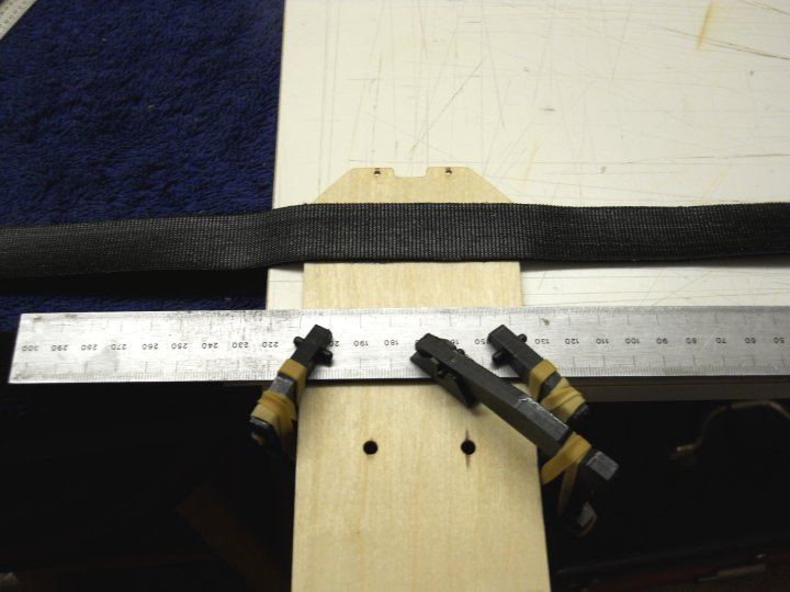
Straps were epoxied to the bottom of the tray, with padding to the inside
|
|
|
The tray was completed and ready for installation
|
|
|
Velcro was added to the bottom of the batteries
|
|
|
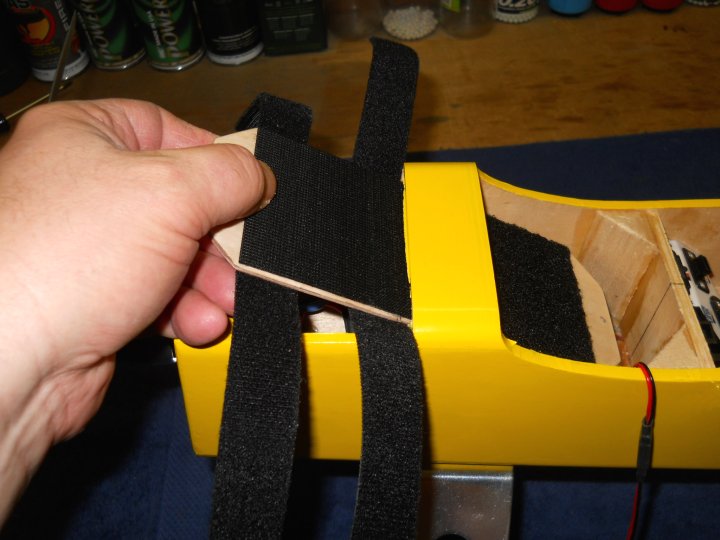
The sides of the tirangle were slightly grooved to allow for the thickness of the velcro straps that wrap around to
clear. A piece of all thread rod made a nice carving tool
|
|
|
The battery tray was installed in the fuselage
|
|
|
Bolts and screws were used to mount the tray
|
|
|
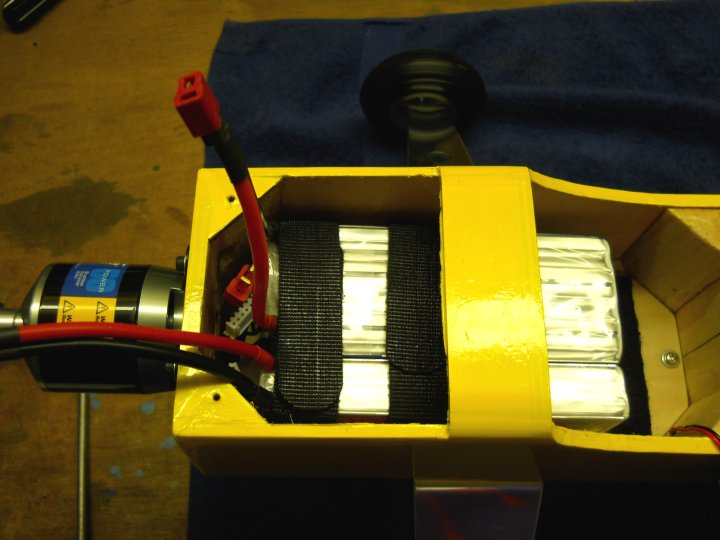
The batteries were test fit through the front opening and were easy enough to install
|
|
|
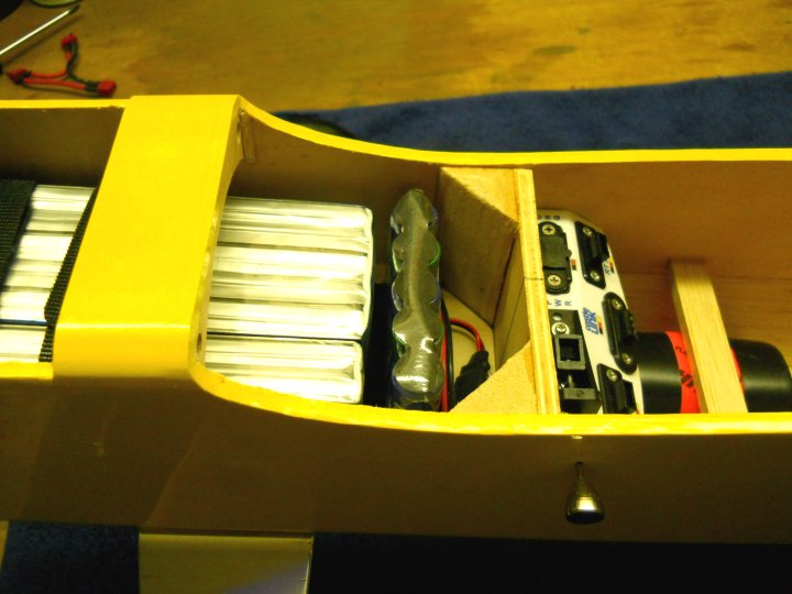
This is one of the possible locations for the receiver battery and it would be padded before final installation
|
|
|
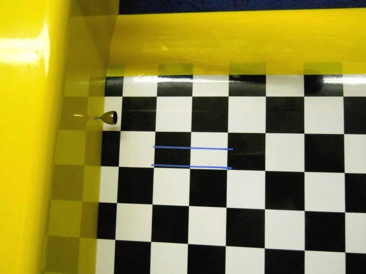
Tape strips were used to mark the inner and outer locations for balancing the aircraft. Marks are at 1 1/2" and 1"
from the rear of the spar and balsa sheeting
|
|
|
Balance for the G-Styk should fall within the previously mentioned range. Unlike the glow version, the balance point
will not change during flight, as there is no fuel tank to empty and change the balance point
|
|
|
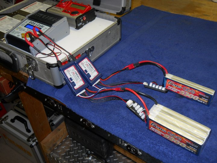
The 5S and 2S batteries are shown being charged as a single 7S battery and all cells will be balanced within .01vdc
of eachother
|
|
|
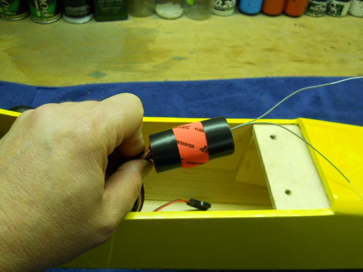
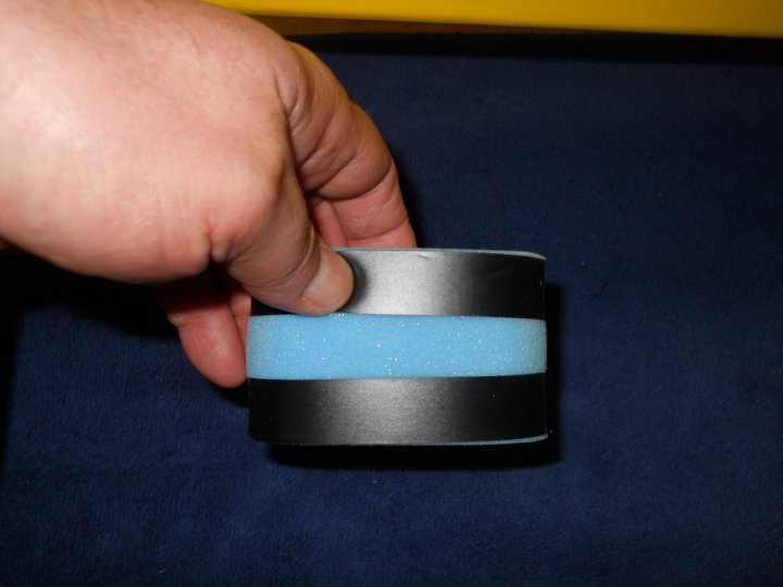
The receiver battery was wrapped in foam for protection and to hold it in place
|
|
|
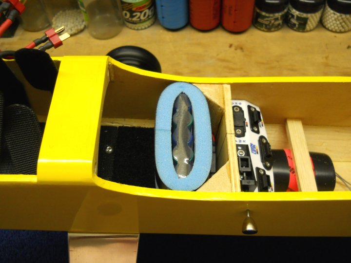
The receiver battery was installed just behind the rear of the main battery packs
|
|
|
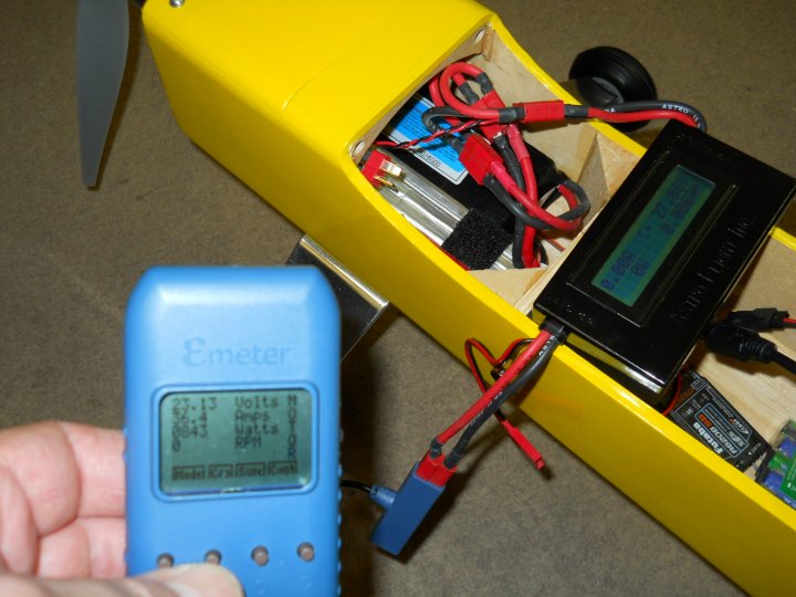
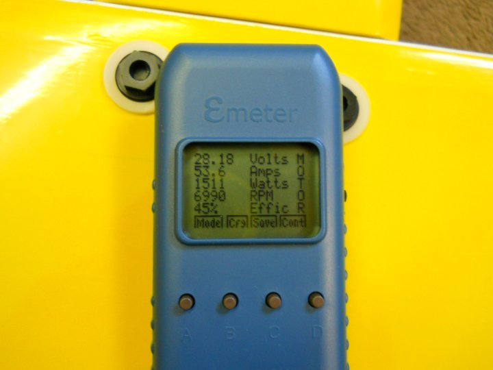
Test results in the ready to fly configuration were very impressive. The airplane has better than a 1 to 1 thrust
ratio and wanted to accelerate vertically out of my hands. With over 1 1/2 Kilowatts of power, it is ready to fly
and should perform very well. Peak data during testing was higher than that shown in the picture and was as follows:
27.9 - Volts 54.9 - Amps 1555 - Watts 10,127 RPM Estimated Flying Speed - 70-80 Mph with 14x8 APC Electric Propeller. Note that the tach read 6990 RPM while the ESC recorded 10,000 RPM and I found that the tach was off and not sensing correctly, as it was set for a three bladed prop |
|
|
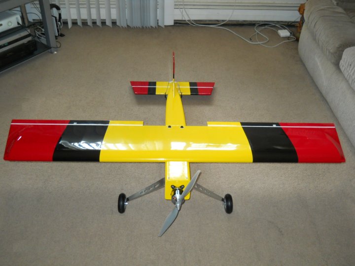
The G-Styk Electric - Front View
|
|
|
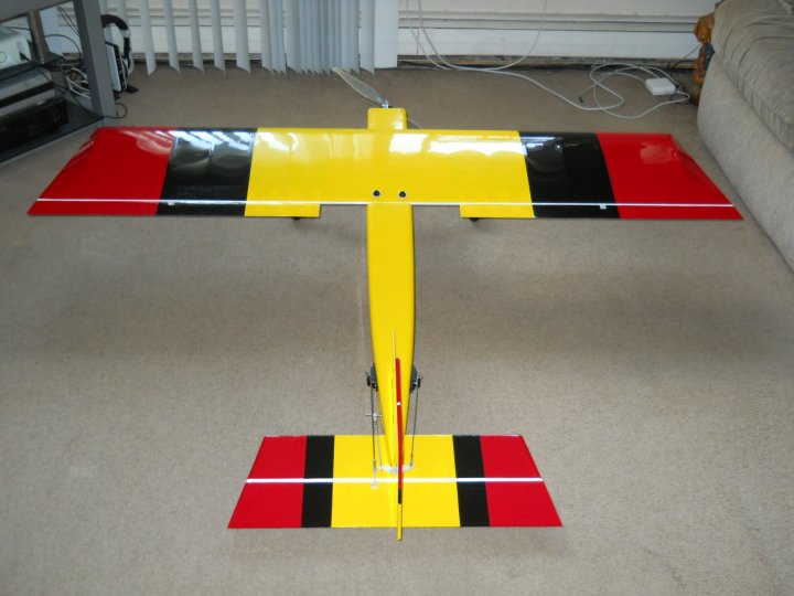
The G-Styk Electric - Rear View
|
|
|
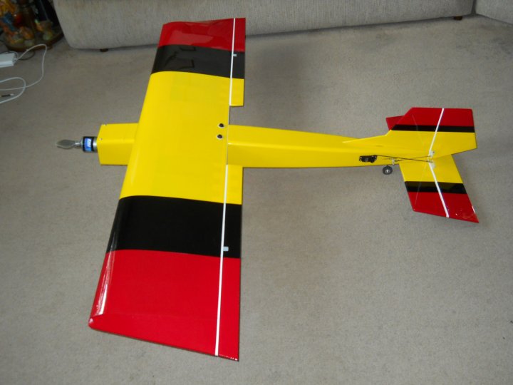
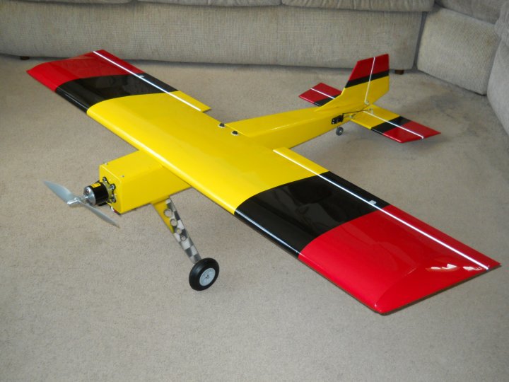
The G-Styk Electric - Side View
|
|
|
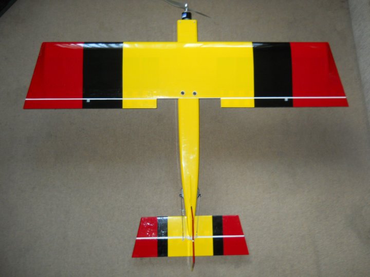
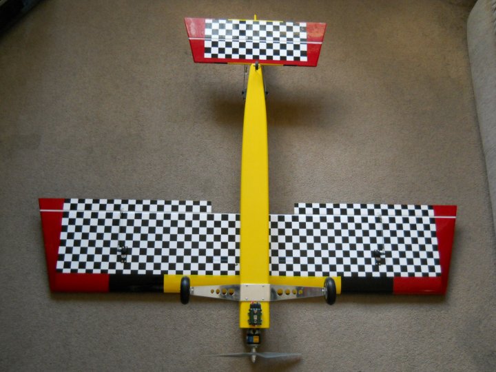
The G-Styk Electric - Top View
|
|
|
The G-Styk Electric - Bottom View
|
|
|
The G-Styk Electric - Completed and ready to fly!
|
|

This Website and all documents herin are Copyright © 2012 www.scalerocketry.com - All rights reserved.
|