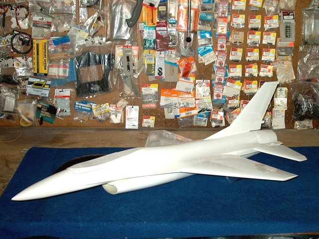
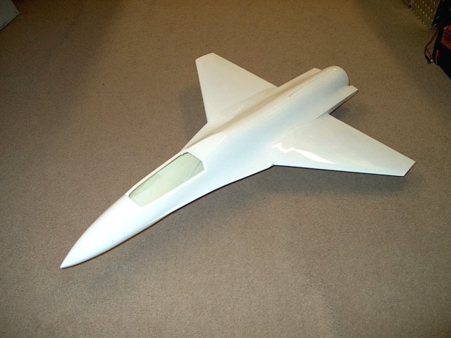
The Wemotec F-16C Fighting Falcon kit as
shown with major assenblies fitted | |
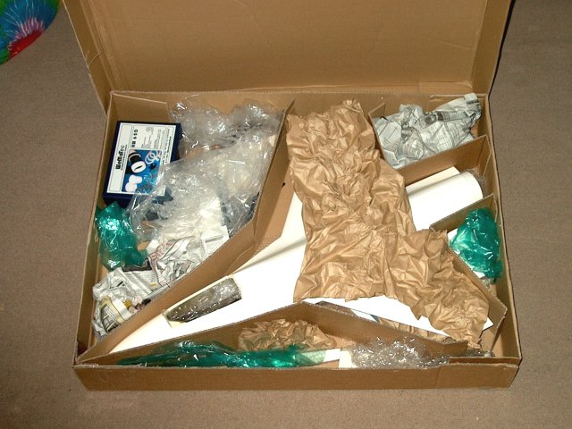
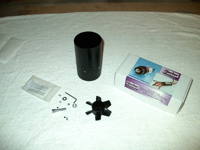
The model comes well packed from the
manufaturer | |
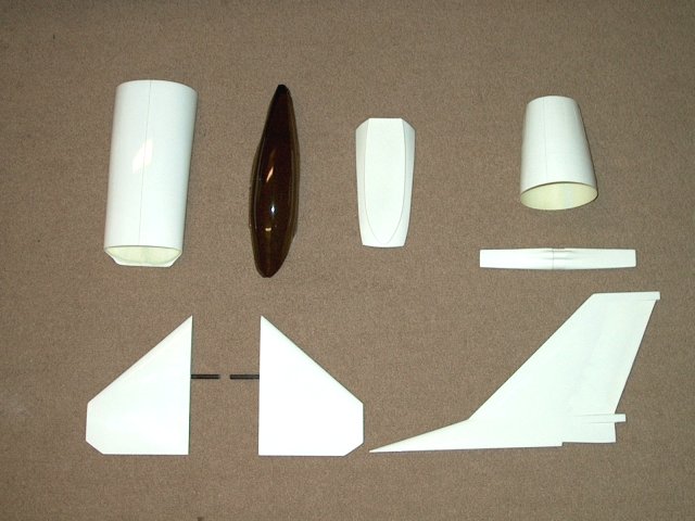
Parts are shown that come with the
kit | |
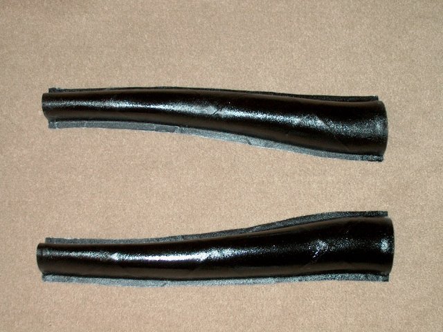
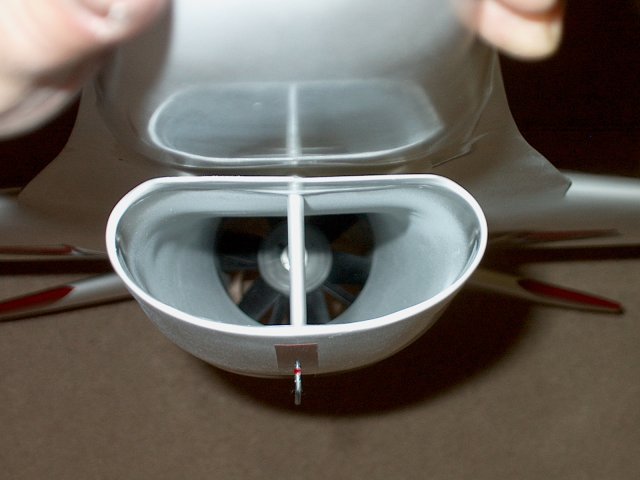
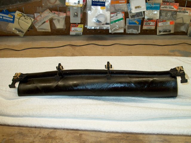
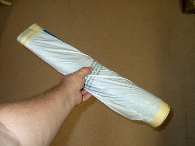
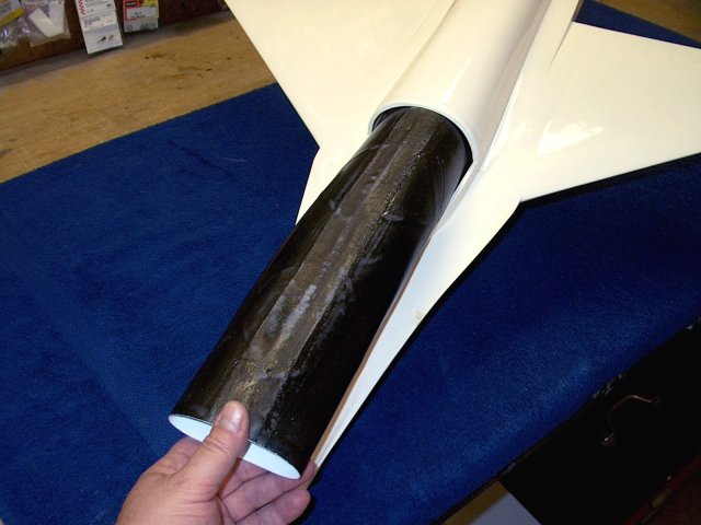
The two halves of the intake tube are made
from carbon fiber | |
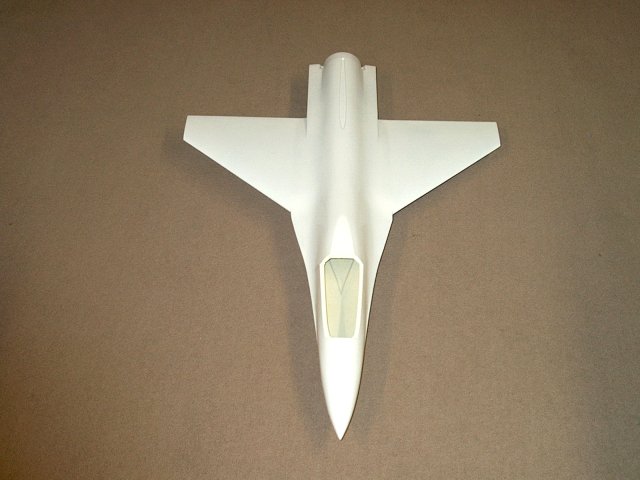
The fuselage and wings are molded as one
piece, keeping the assembly lightweight
| |
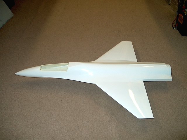
Side view of the scale shape of the
fuselage | |
Front view shown
| |
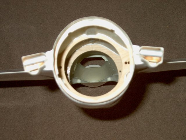
Rear view of pre-installed formers
| |
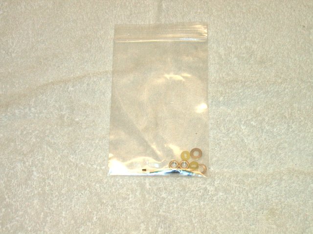
Bag of hardware is shown that is included
with the kit | |
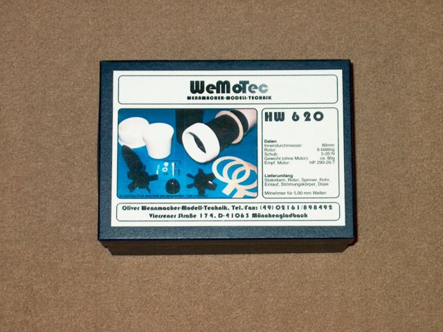
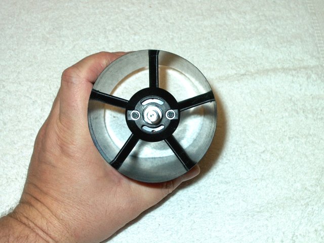
The HW 620 86mm custom Midifan from
Wemotec is included in the kit | |
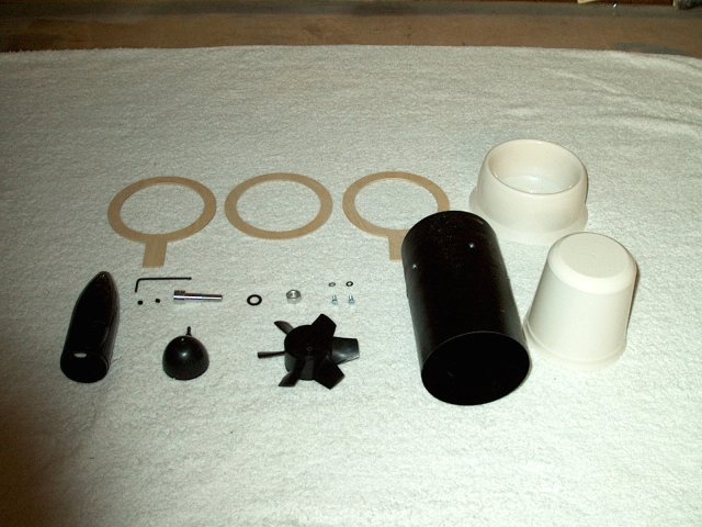
Contents of the fan assembly are
shown | |
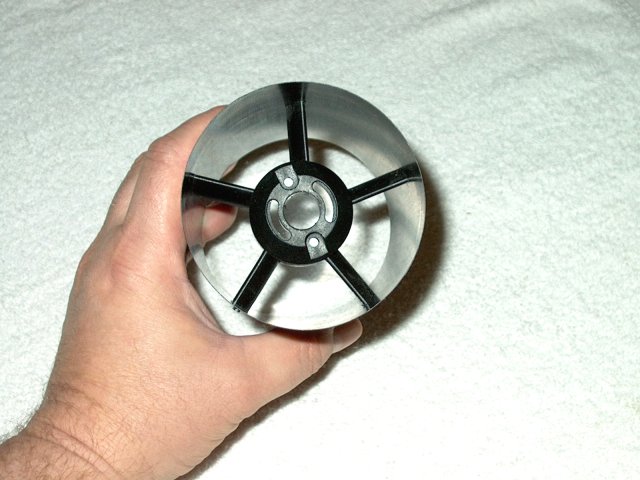
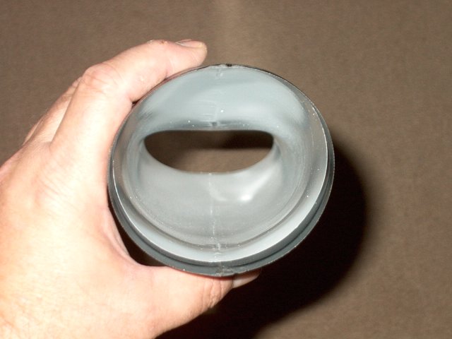
The fan housing is molded from carbon
fiber to keep it light weight and strong
| |
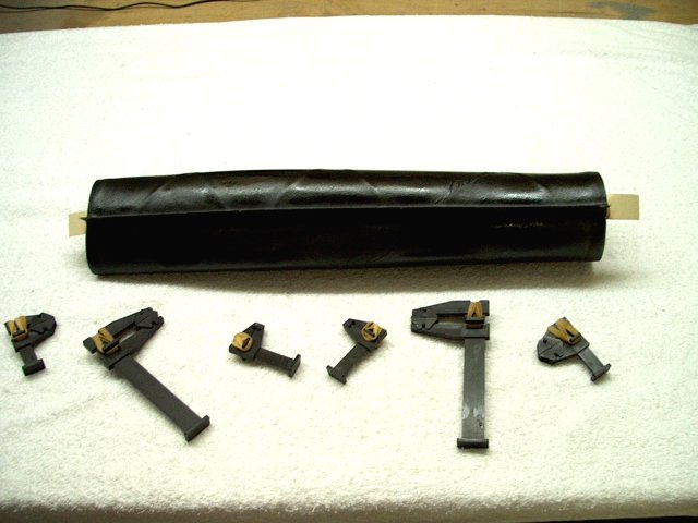
Shown are the basic parts from the fan kit
that are required to assemble it for this model
| |
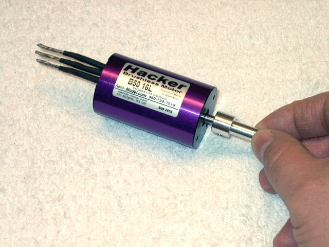
Construction begins with the power plant
assembly. Install the shaft adapter for the fan over your
motor shaft | |
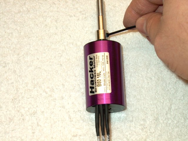
Apply Loktite to the shaft adapter set
screw and install it in the adapter
| |
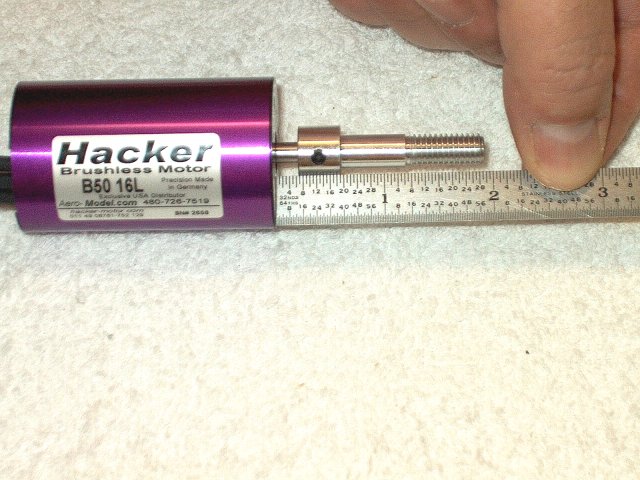
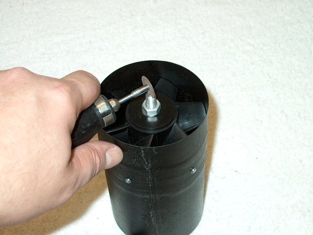
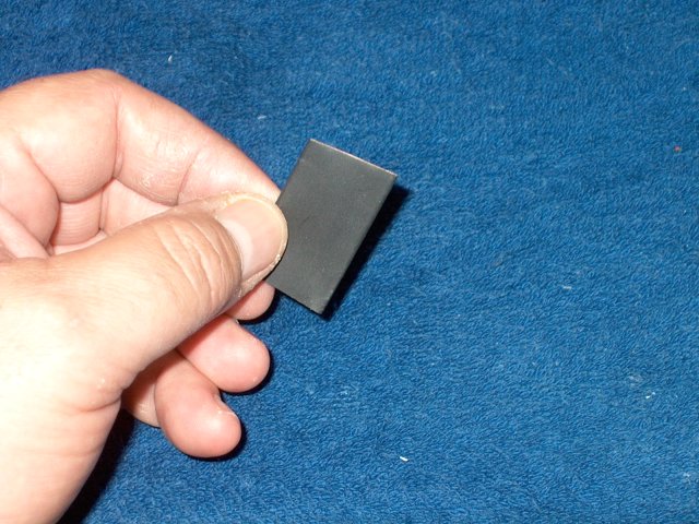
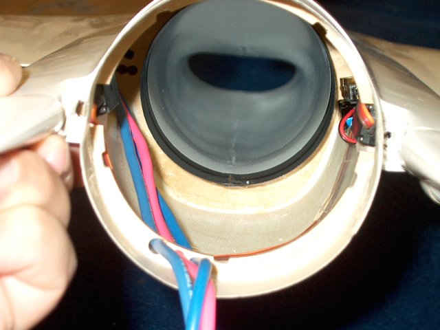
Make sure there is enough clearance on the
adapter so the fan does not rub on the housing. A good
starting point is shown. | |
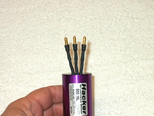
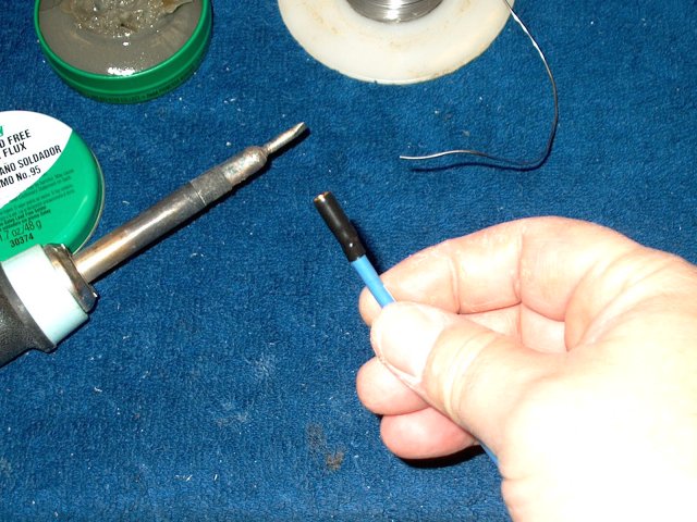
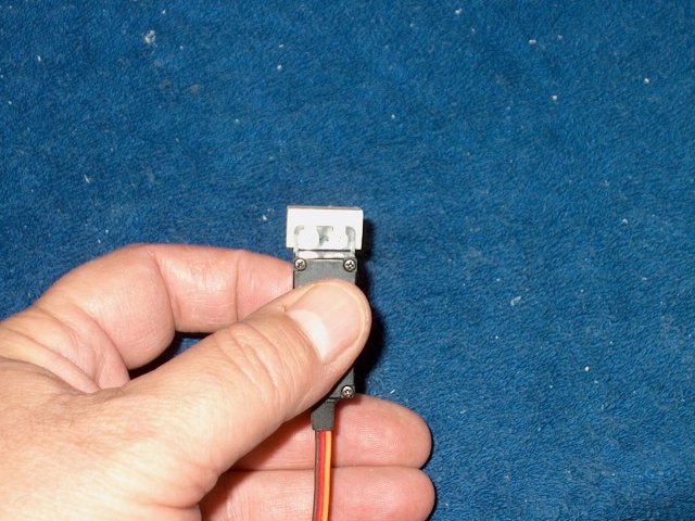
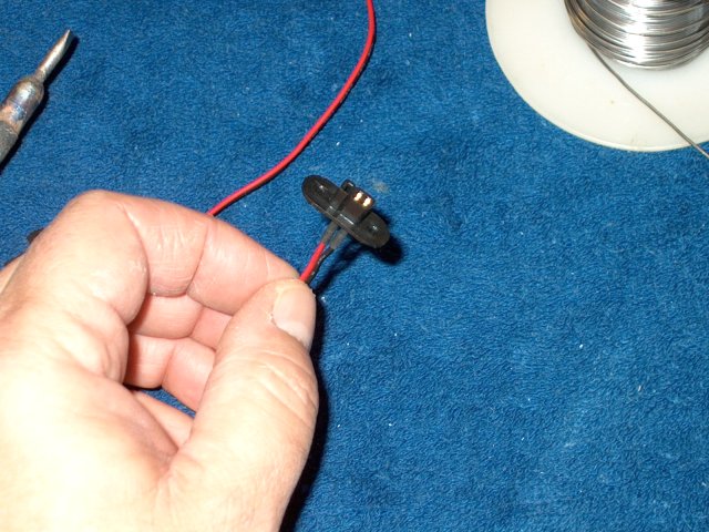
Install plugs if you wish on the motor
wires | |
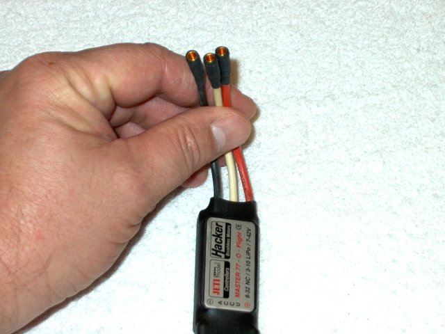
Install sockets on your ESC to match the
motor | |
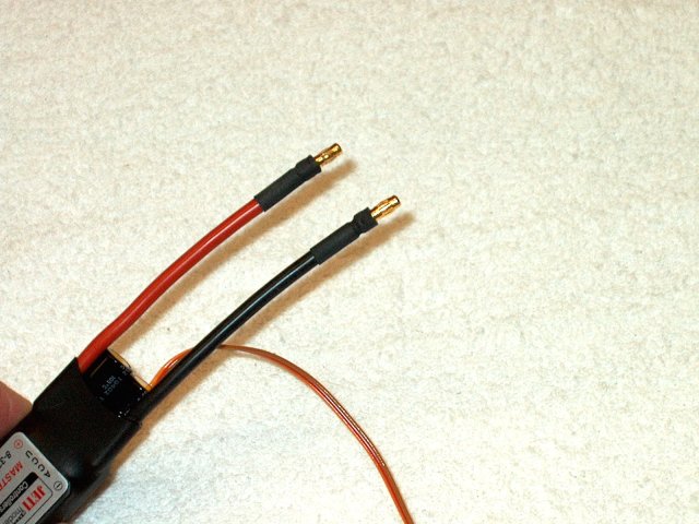
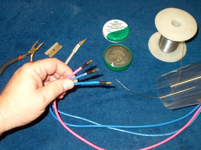
Plugs are also installe don the power
wires for the ESC. This allows you to interchange motors and
ESC's if necessary | |
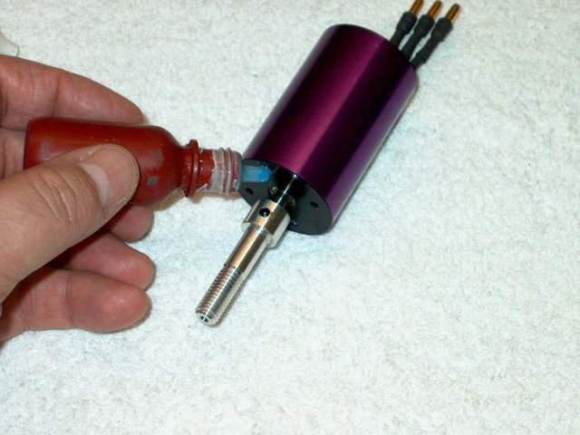
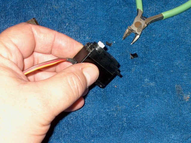
Loktite is applied to the motor threads
only!!! Do Not apply blue Loktite to the screws as it will
touch the housing and can disolve the housing plastic. Clean
up any excess Loktite | |
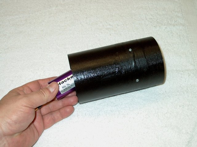
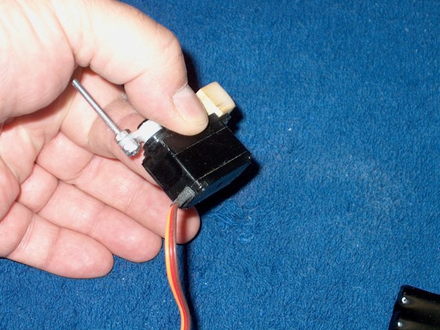
Install the motor in the housing
| |
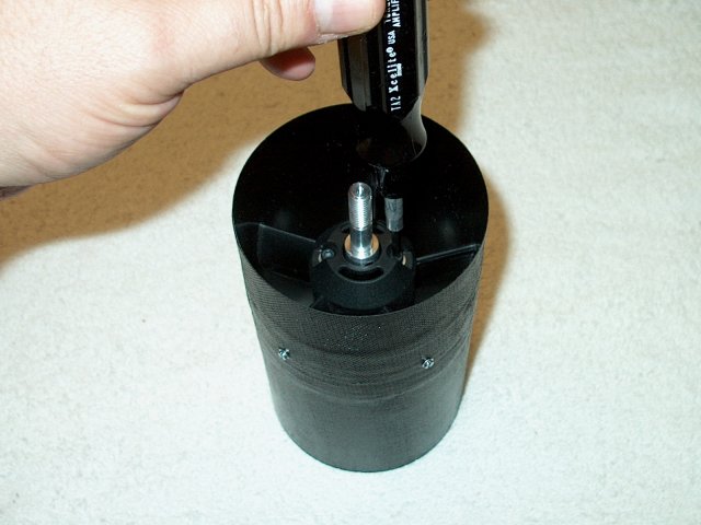
Install the retaining screws in the motor
to mount it to the housing | |
Insure the motor is centered in the
assembly | |
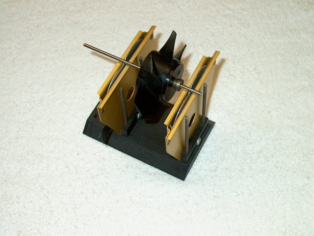
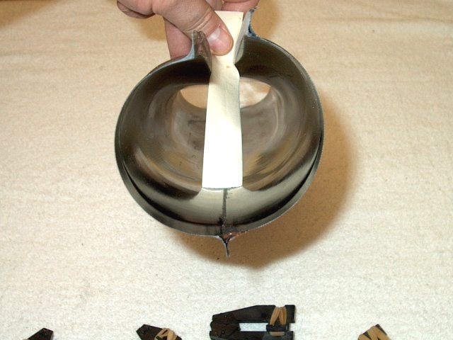
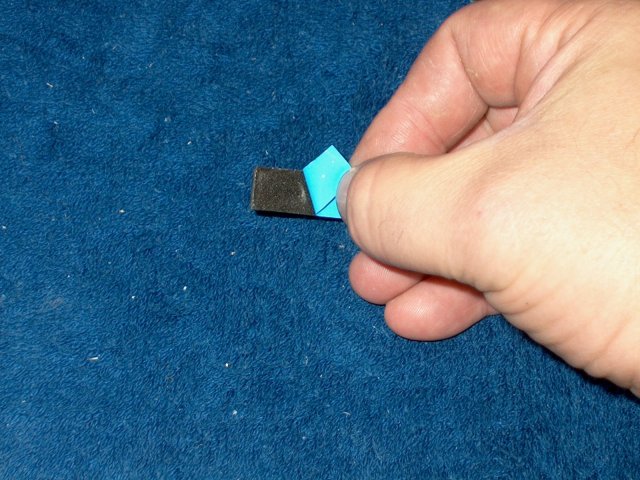
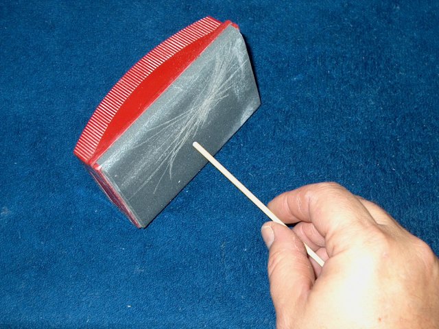
Use a tool to balance your fan assmebly.
Small pieces of electrical tape can be placed inside the fan
outer hub and CA'ed in place to adjust balance
| |
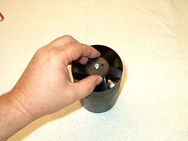
Install the fan rotor on the shaft
adapter | |
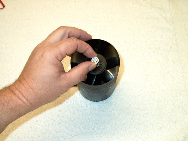
Install the supplied washer, then the
aluminum nut | |
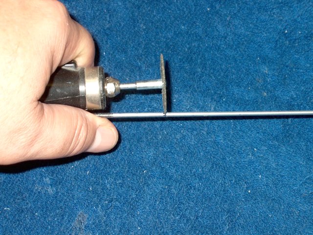
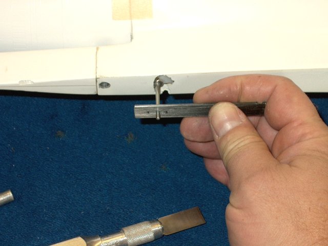
A slot can be cut into the shaft to allow
for tightening. Be sure to cover the motor anf fan with a
cloth so metal dust from cutting doesn't contaminate the
assembly | |
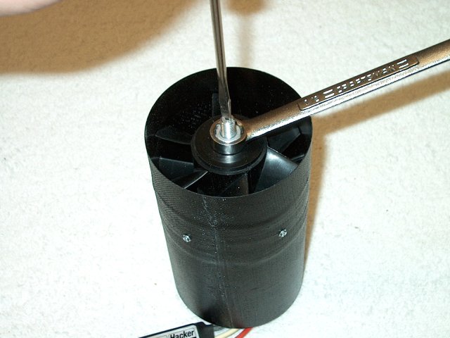
Use a screwdriver to hold the shaft in the
slot you cut, then tighten the nut with a wrench
| |
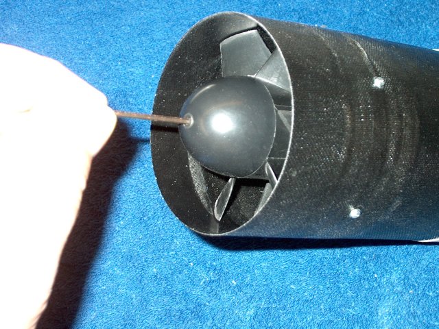
Install the hub if desired and tighten
with the supplied screw | |
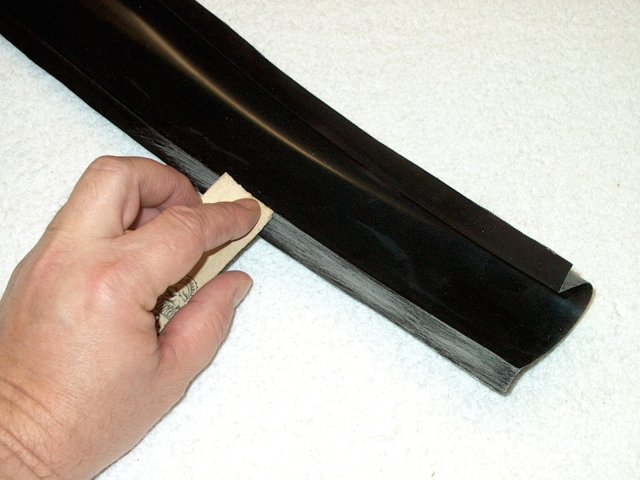
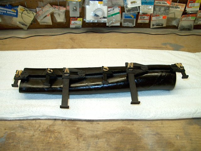
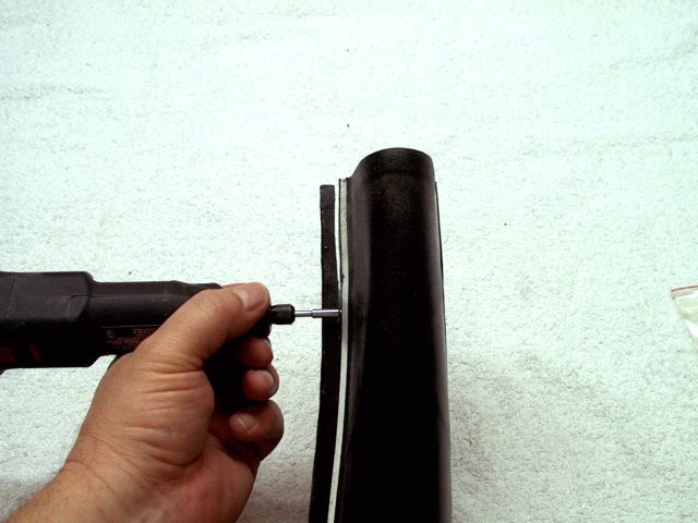
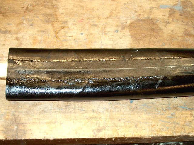
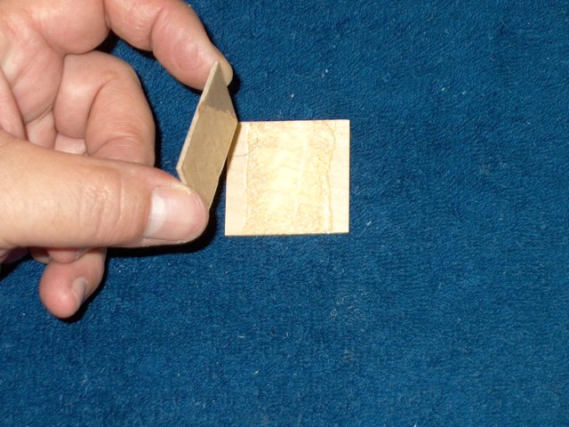
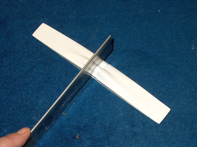
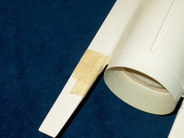
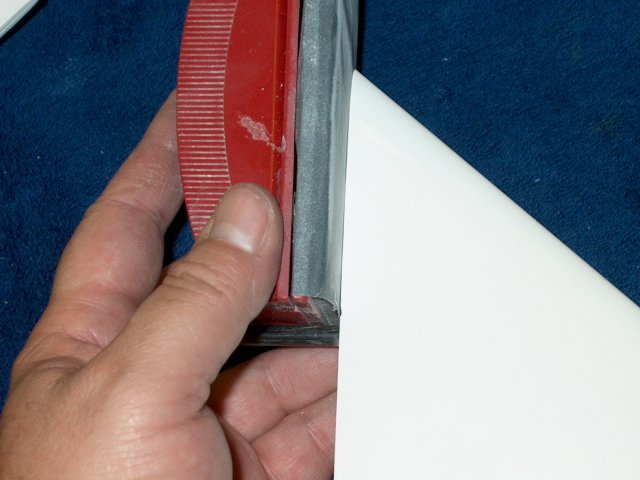
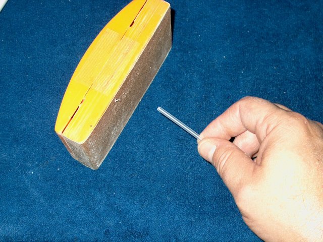
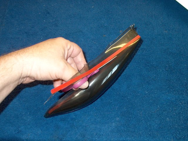
Sand the outer lips of both halves of the
carbon fiber intake duct | |
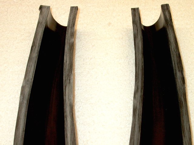
Halves are shown preped and ready to be
glued | |
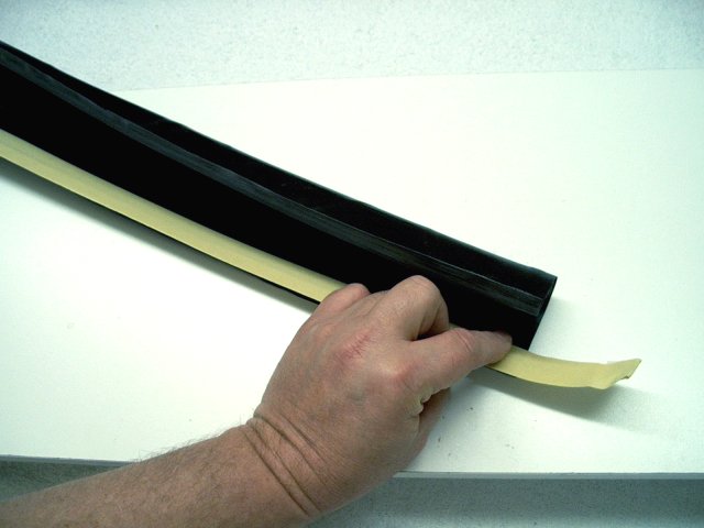
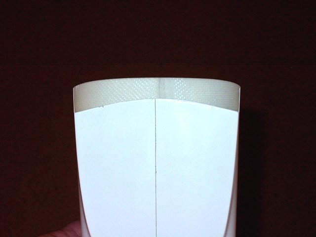
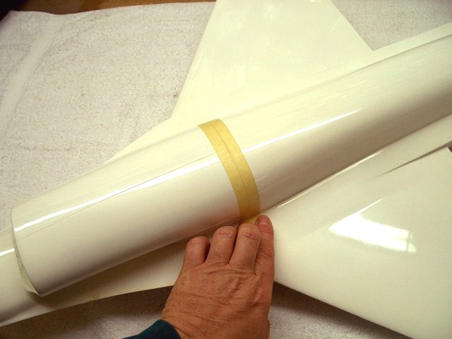
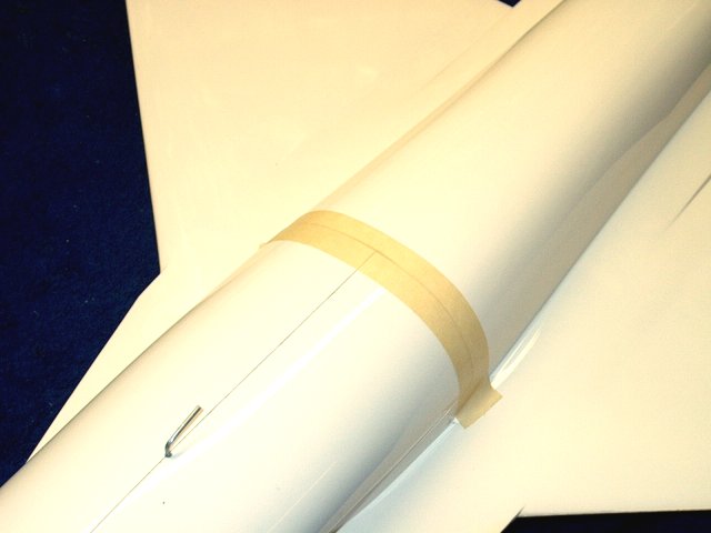
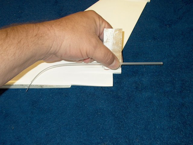
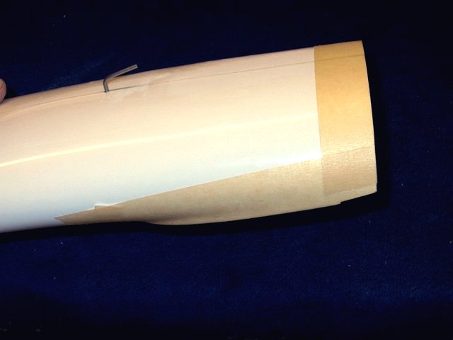
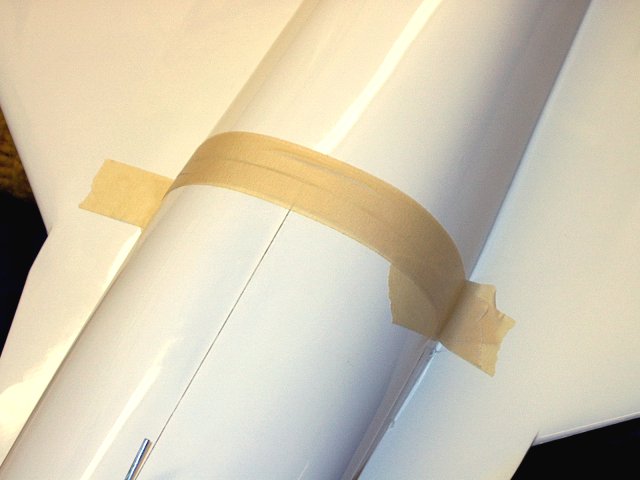
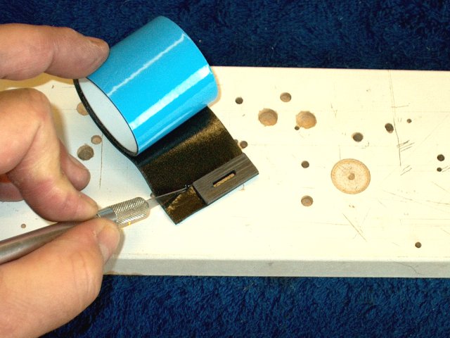
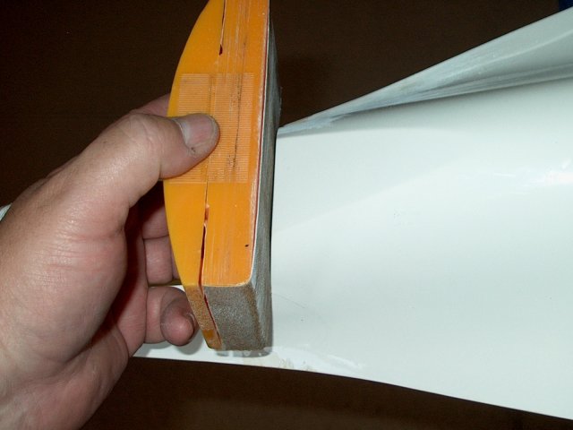
Apply a piece of masking tape that was
made 3 layers thick along the lenth of the seam
| |
Install the second half, using th masking
to hold it in place | |
Apply epoxy with a small brush along the
seam lip | |
Clamp the assembly until the eopxy
sets | |
Remove the clamps once the epoxy
sets | |
Remove the tape from the inside of the
duct | |
Repeat the procedure for the other side,
applying a 3-layered tape strip tot he inside, then epoxy
along the seam | |
Clamp the second half and allow the epoxy
to set | |
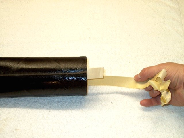
Remove the clamps and tape
| |
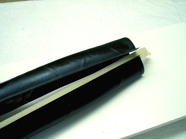
The tape prevents overspill of epoxy in
the inside of the intake | |
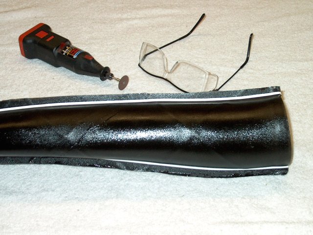
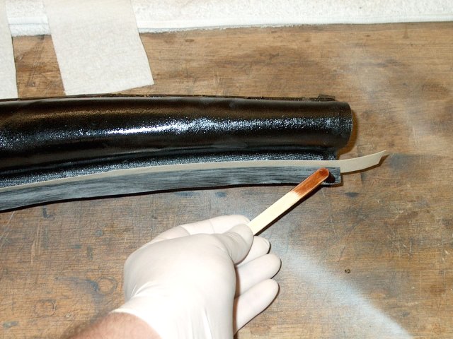
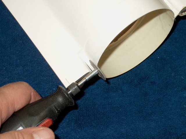
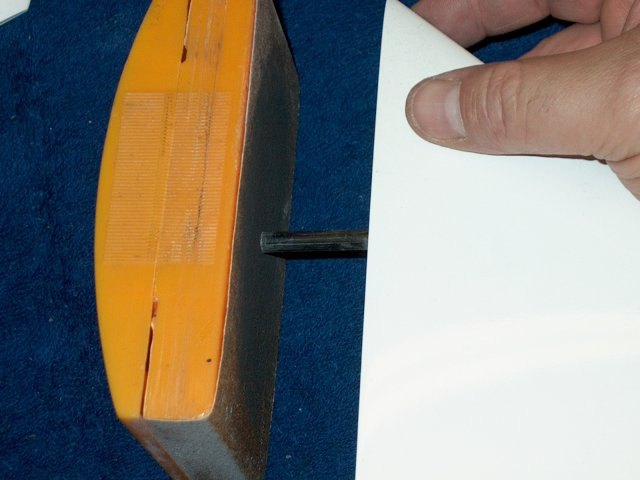
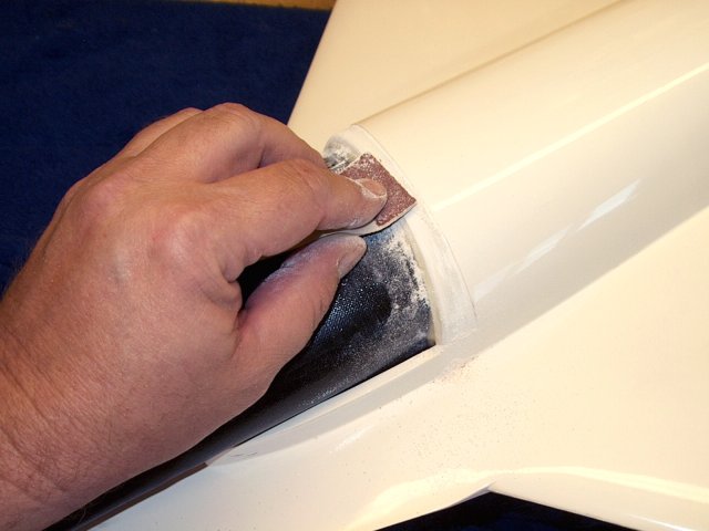
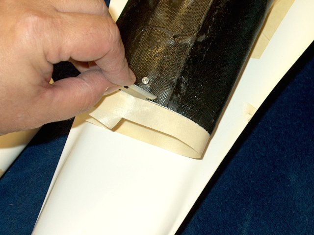
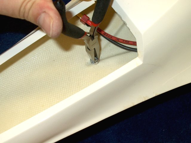
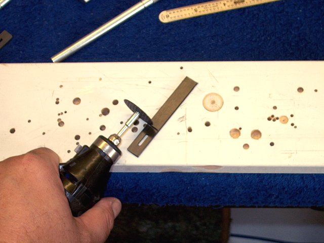
Use a dremel and cutting wheel to remove
most of the lip | |
Remove the lip from the other side
| |
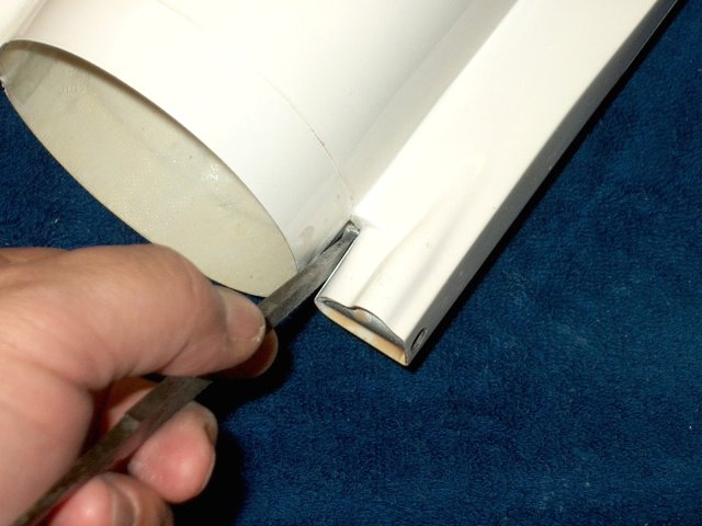
Cut off as much of the lip as you
can | |
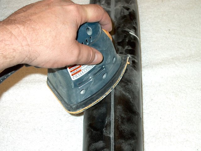
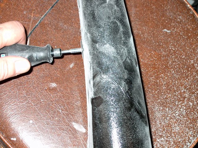
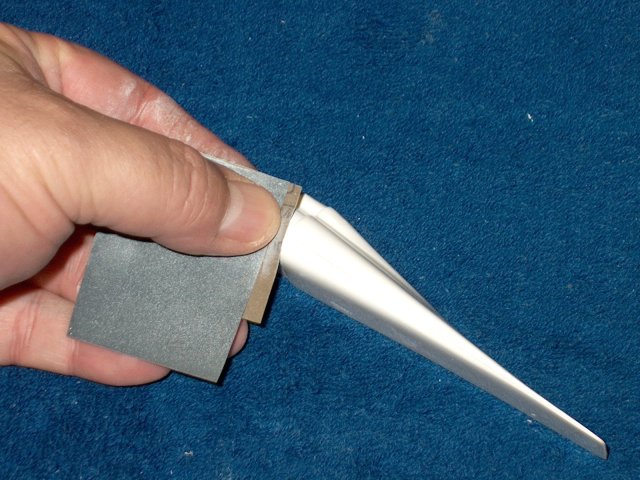
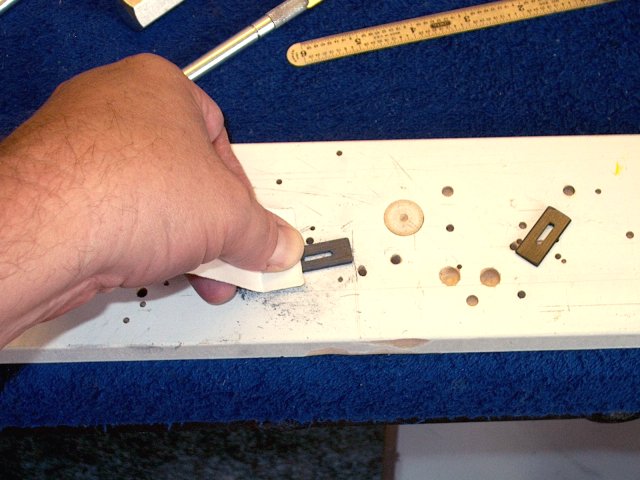
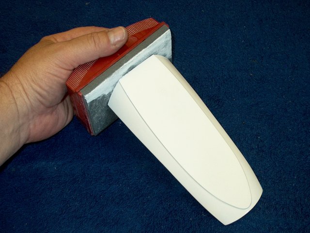
Sand the remaining area until it si nearly
flush | |
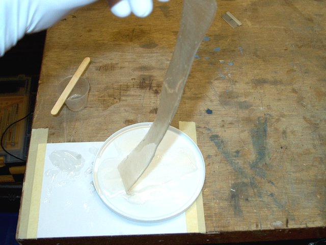
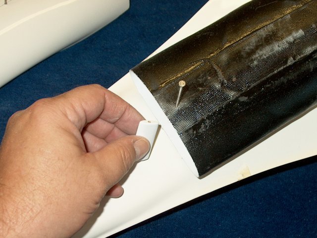
Prepare a 2" strip of 5oz fiberglass cloth
by soaking it in resin | |
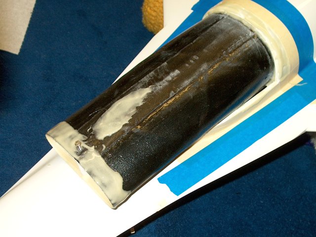
Apply the cloth along the seam, then
remove all excess and allow it to set
| |
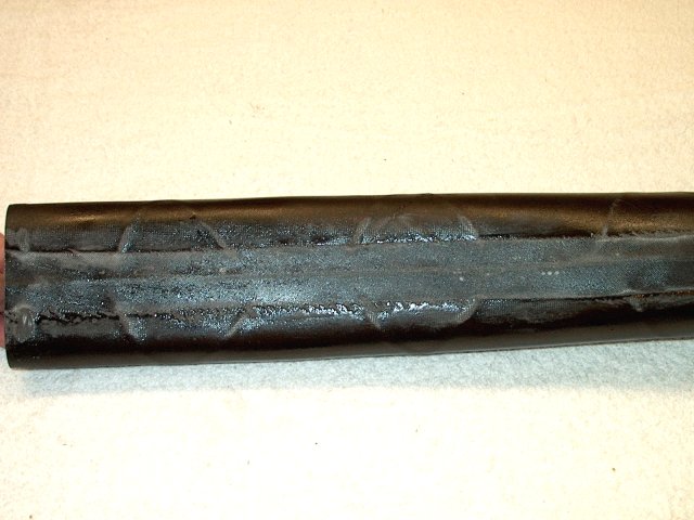
Apply a second strip to the other seam
along the bottom | |
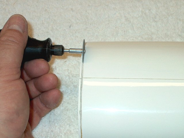
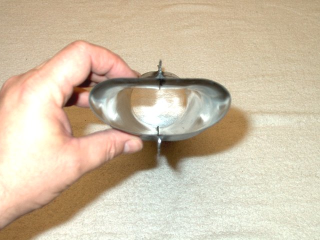
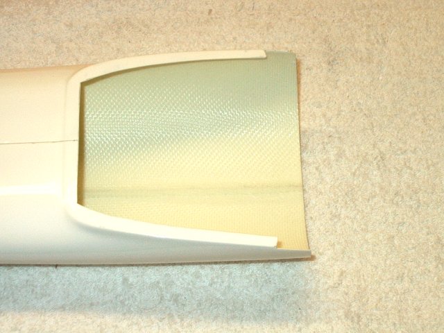
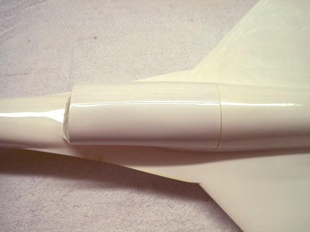
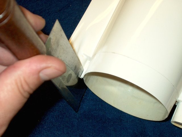
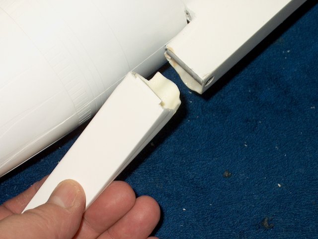
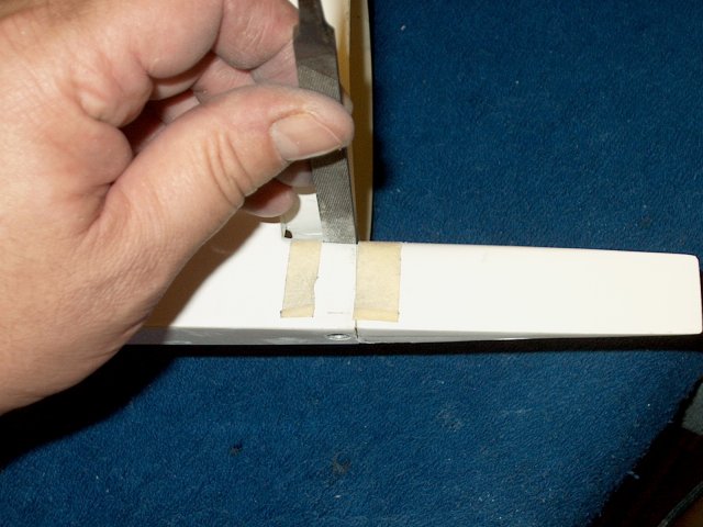
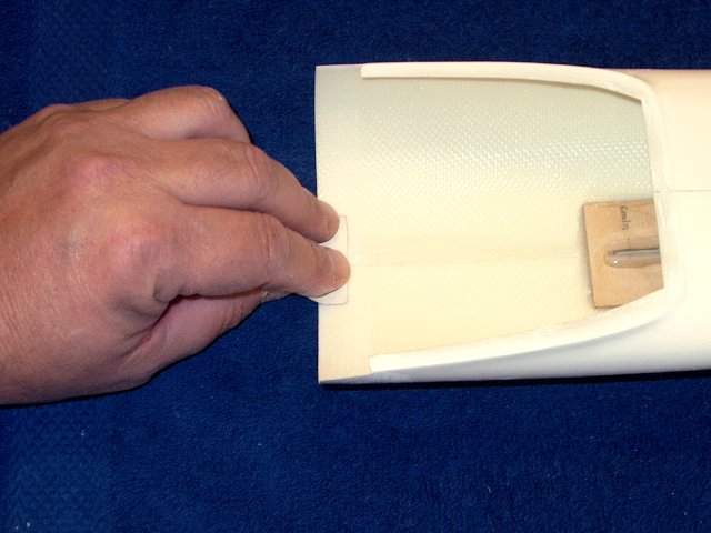
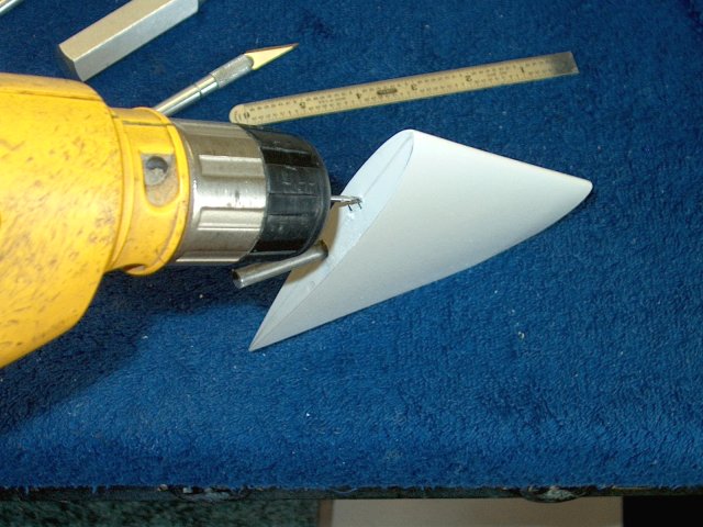
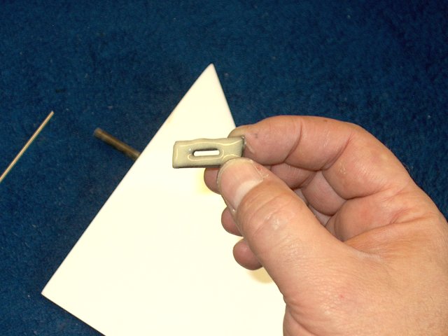
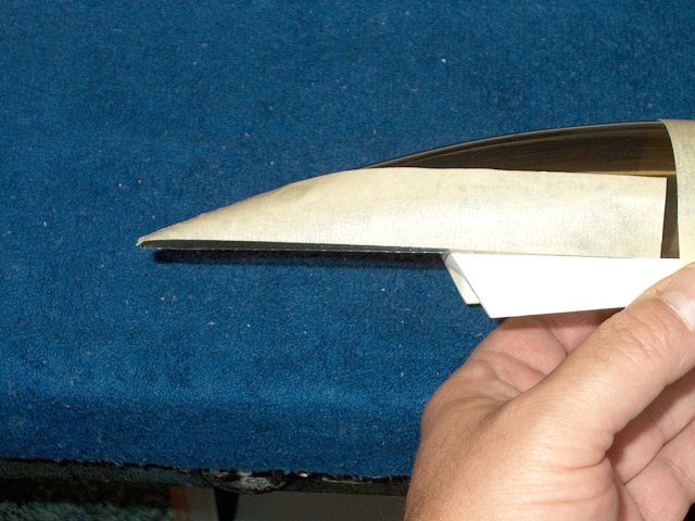
Trim the rear of the Intake Cover as
shown | |
Trim the top of the cover along the
molding lines | |
Remove the trimmed fiberglass and
sand | |
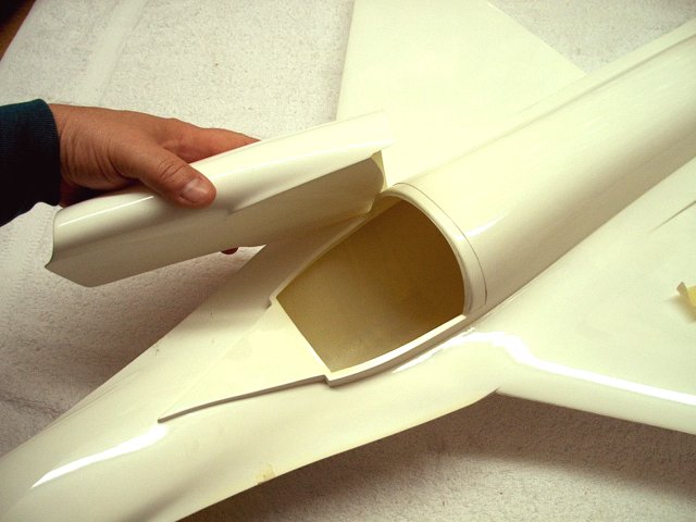
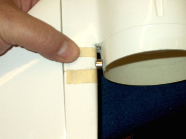
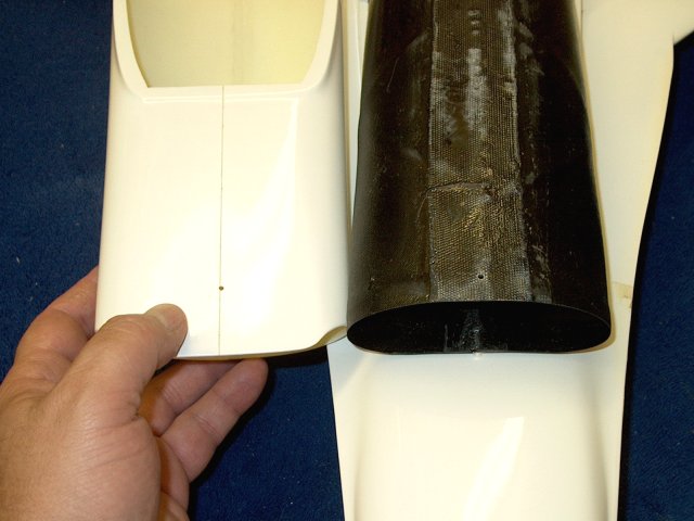
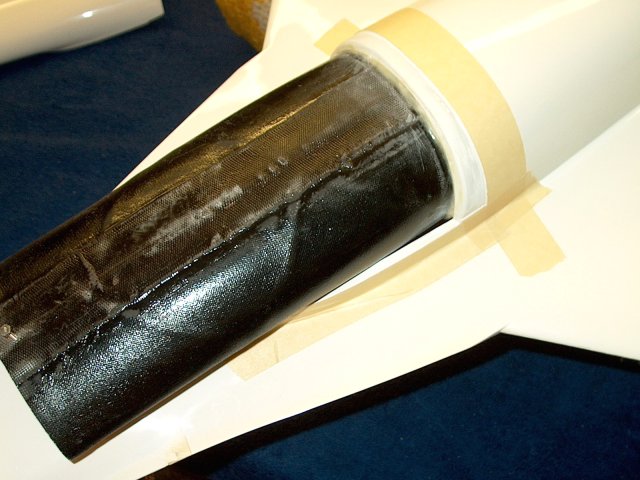
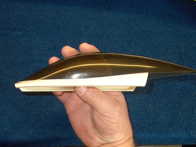
Install the fiberglass intake on the
fuselage and check for fit, then trim as necessary
| |
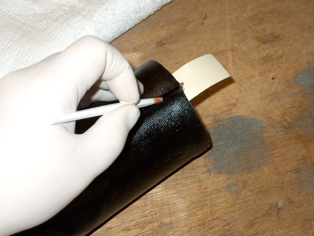
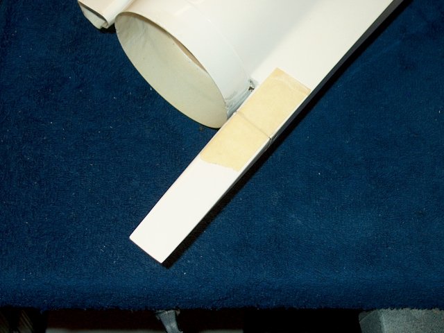
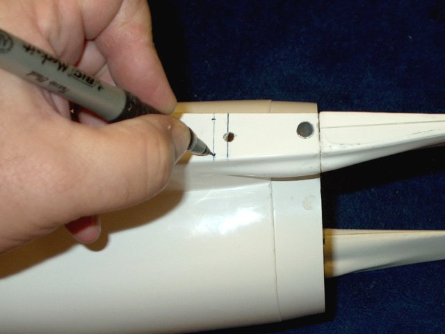
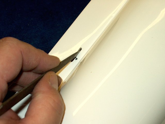
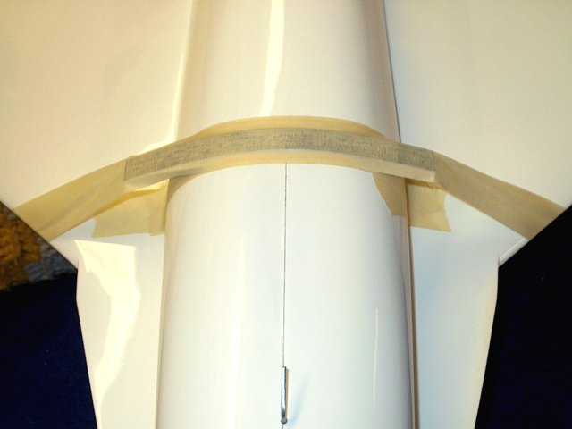
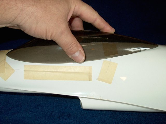
Use tape to hold the intake in
position | |
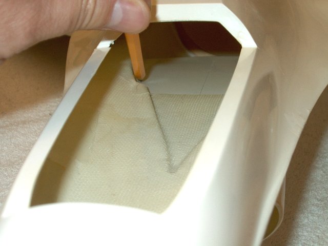
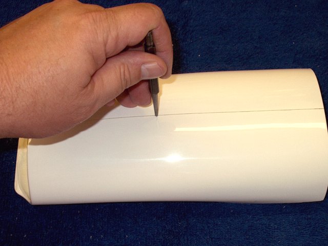
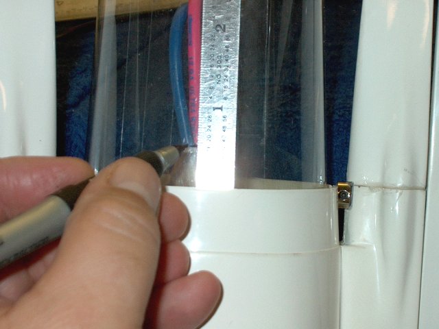
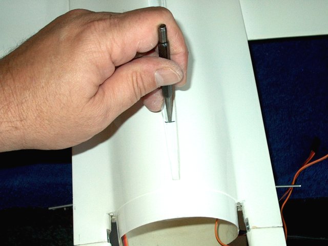
Use a pencil to transfer the inside
pattern of the fuselage to the top of the intake
| |
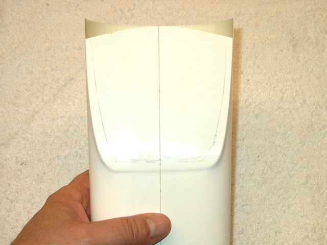
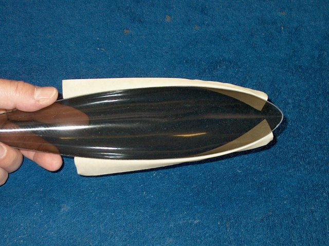
Pattern is now drawn on the intake
| |
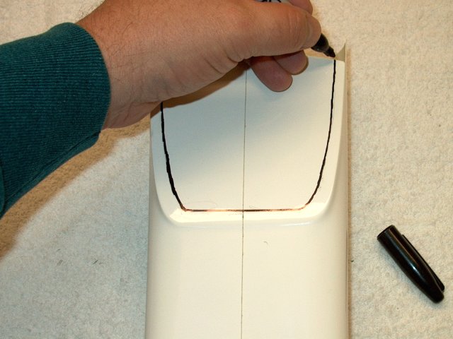
Outline the pattern in marker so it is
easier to see | |
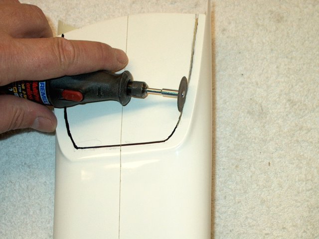
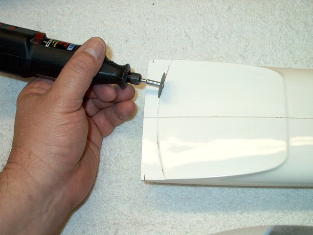
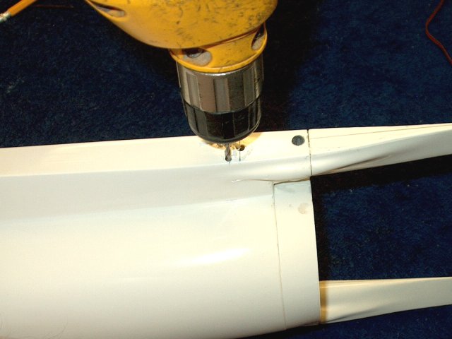
Use a Drenel and cutting wheel to rought
cut the marked area | |
Remove the center piece
| |
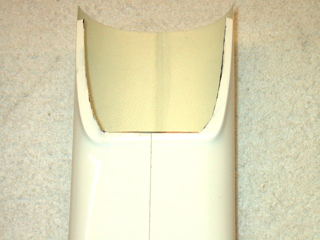
Sand the edges to a smooth finish, then
remove marks with alcohol and a paper towel
| |
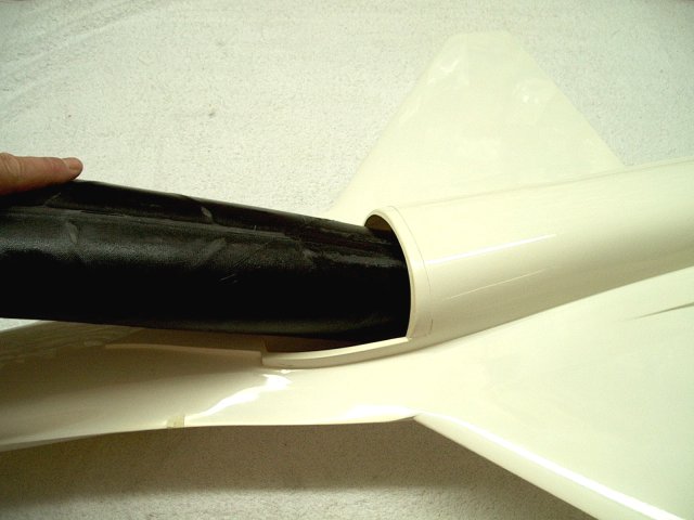
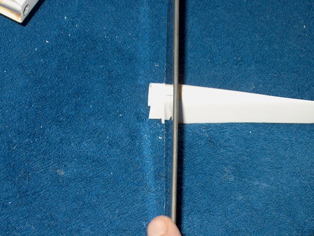
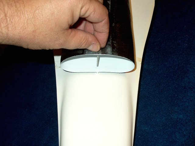
Install the carbon fiber intake duct in
the fuselage | |
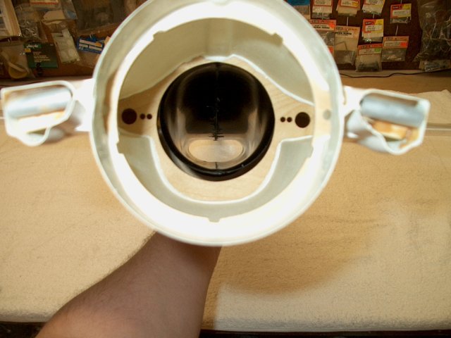
Check for fit at the rear former
| |
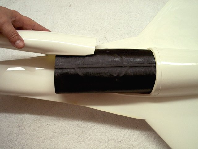
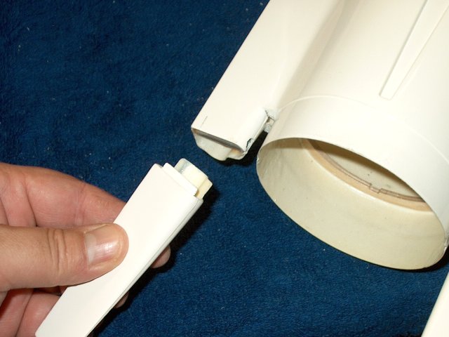
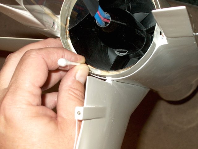
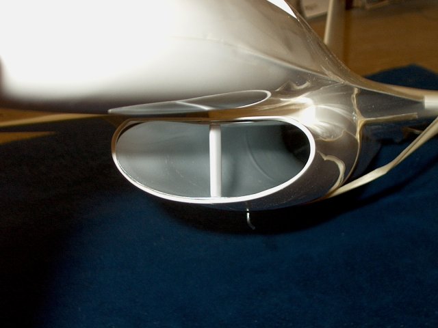
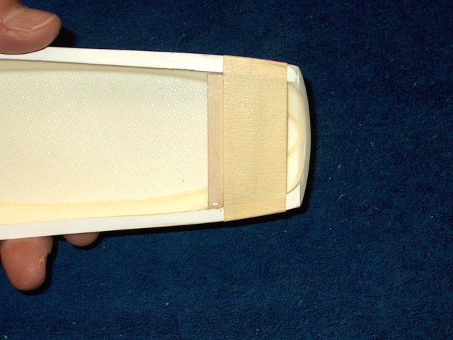
Install the intake cover and make sure it
does not bind on the duct | |
Check the fit of the cover
| |
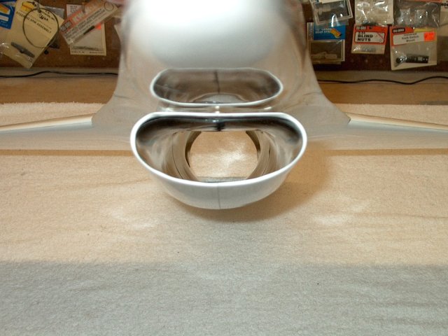
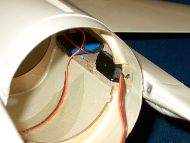
Make sure the edge of the inner carbon
fiber duct is flush against the bottom inside ridge of the
fiberglass intake cover | |
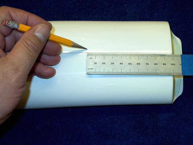
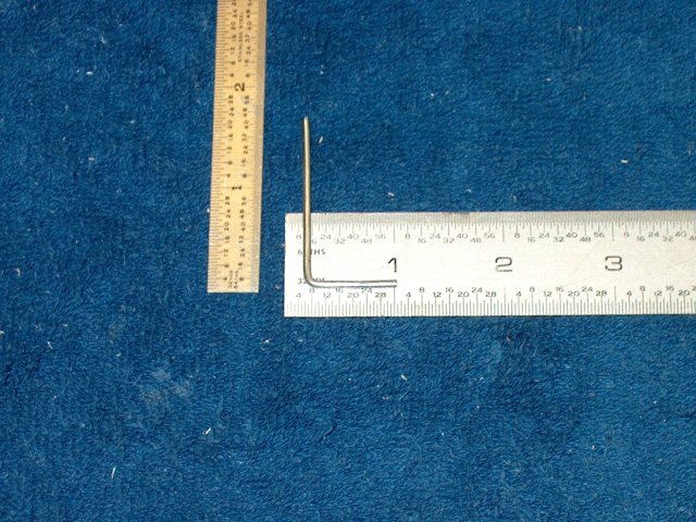
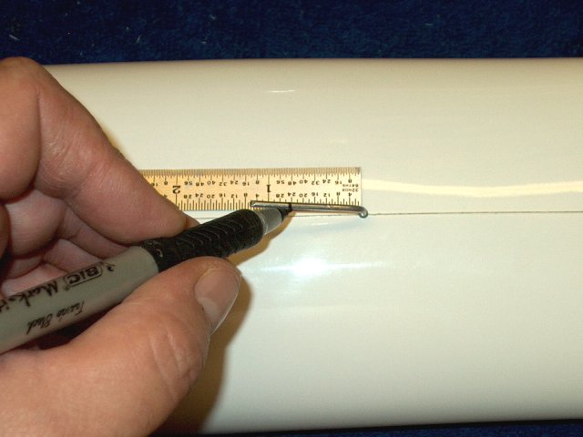
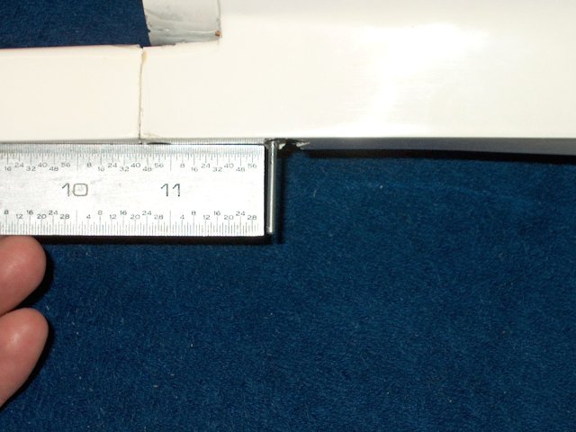
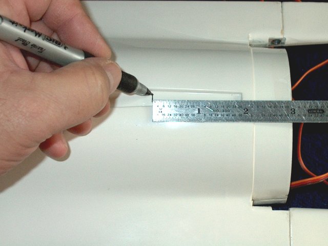
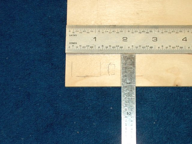
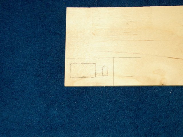
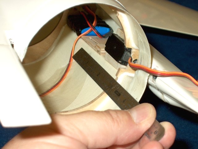
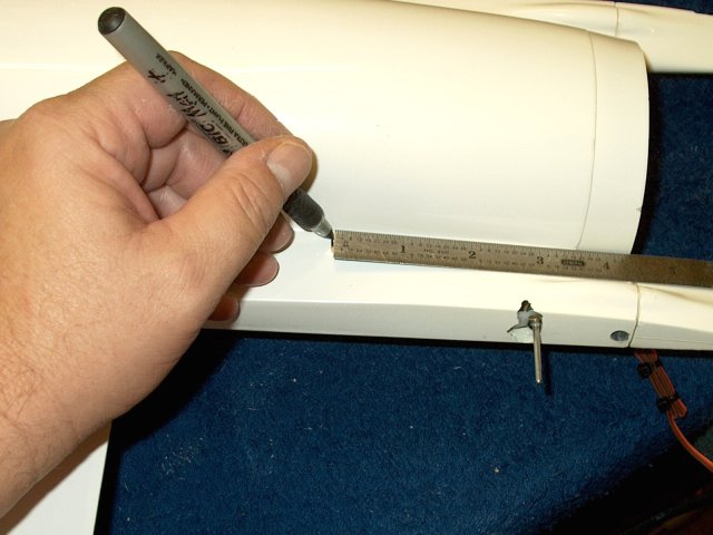
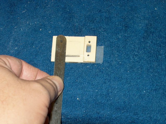
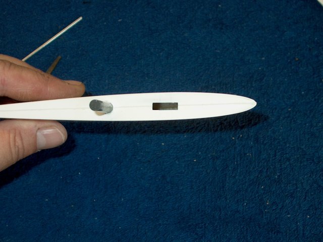
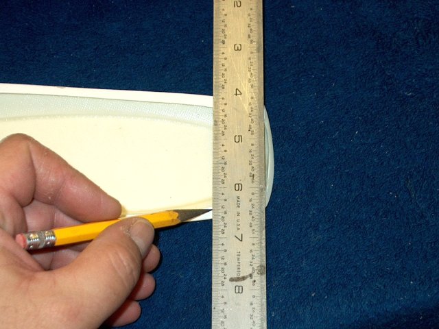
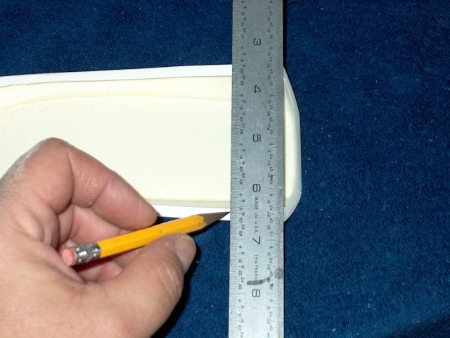
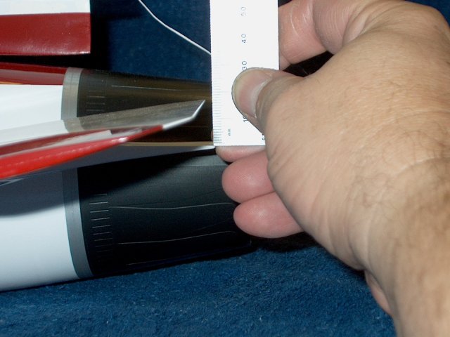
Make a mark on the bottom of the cover
100mm from the front | |
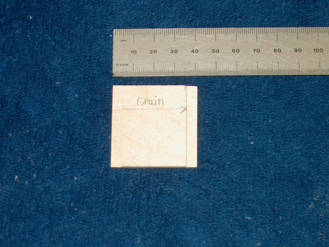
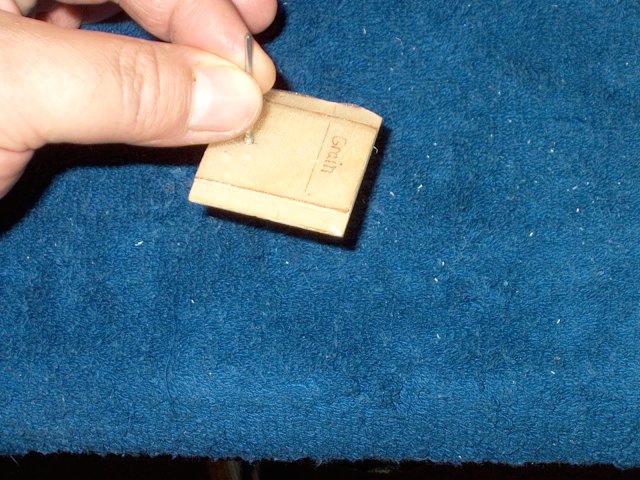
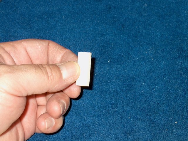
Make a 1/16" ply plate 40mm x 40mm and an
inside 1/16" plate 30mm x 40mm. Note the grain
orientation...this is important | |
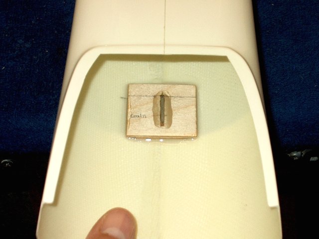
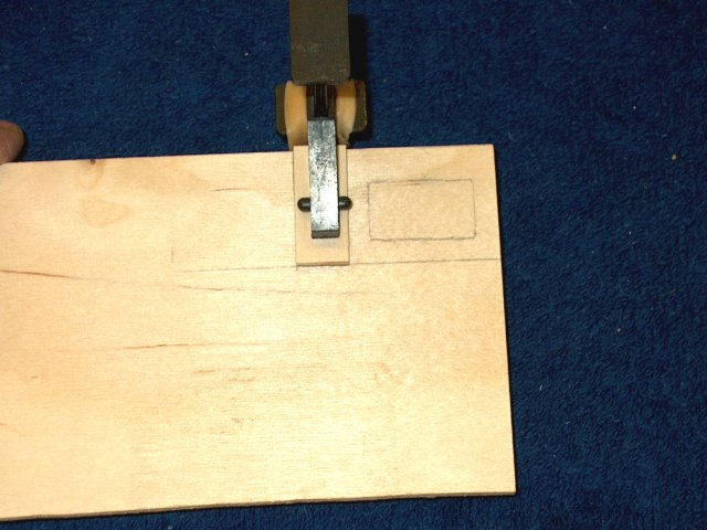
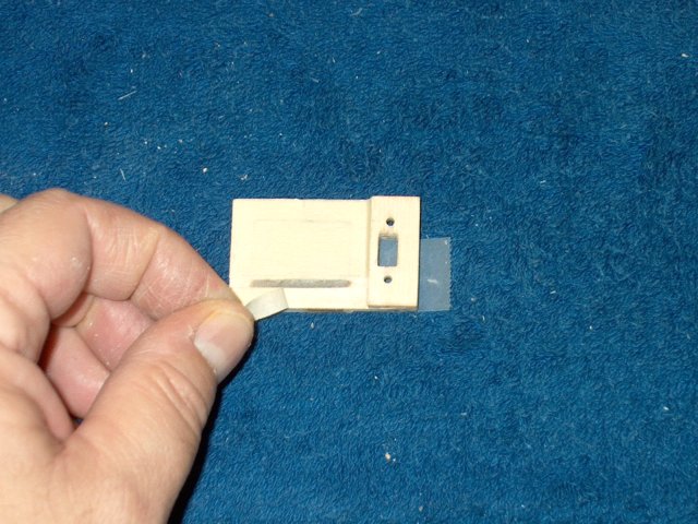
Epoxy the two halves together, making sure
the inner place is centered | |
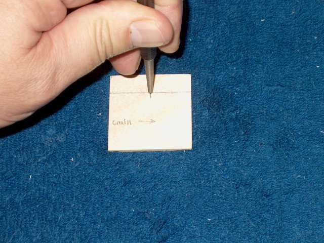
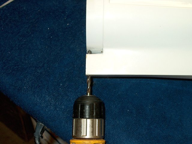
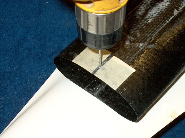
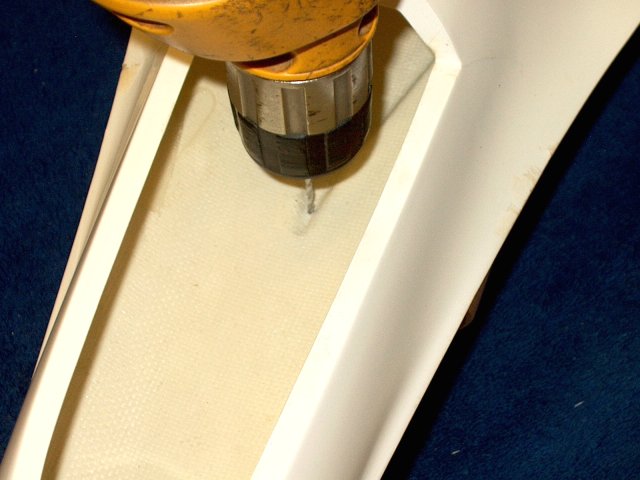
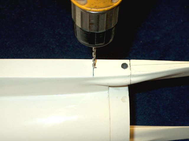
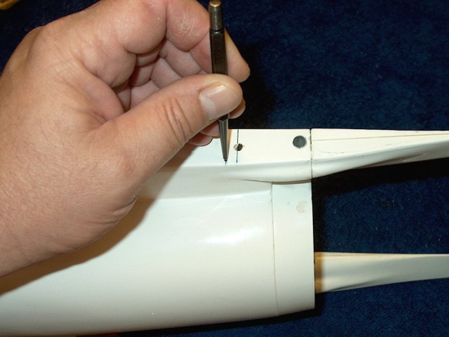
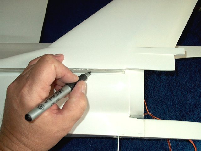
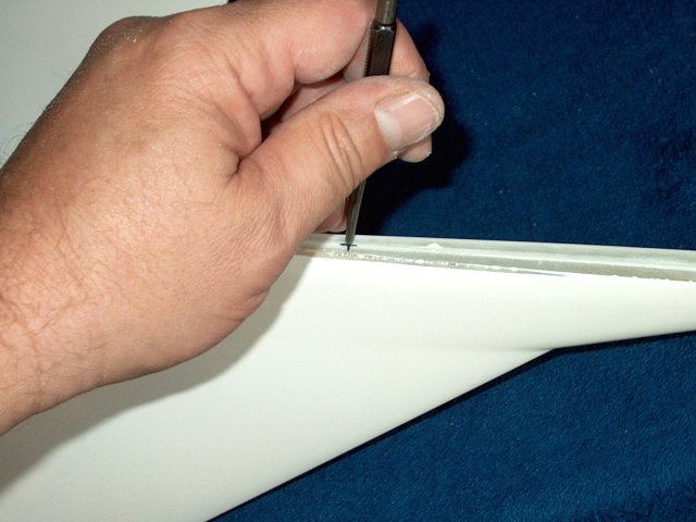
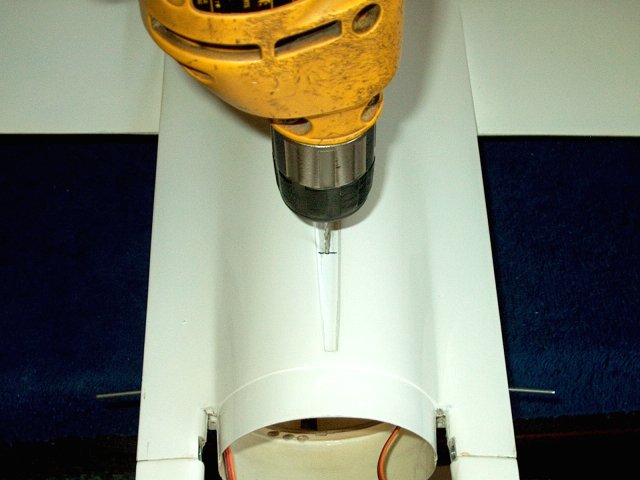
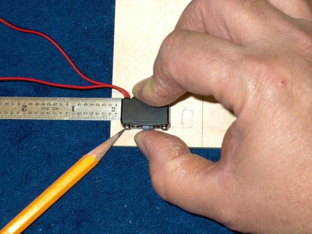
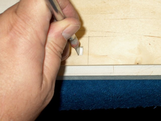
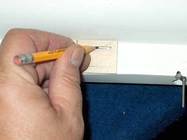
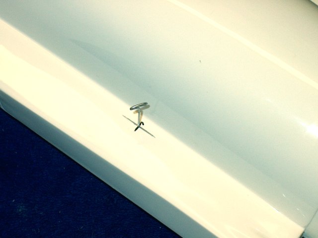
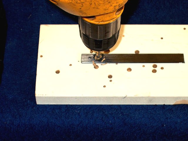
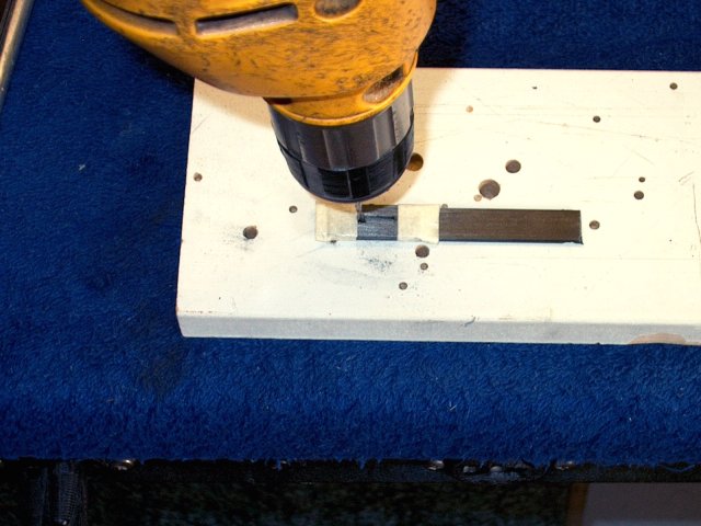
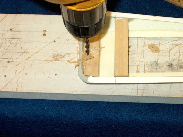
Use a punch to make a mark for drilling at
the 100mm line you drew earlier | |
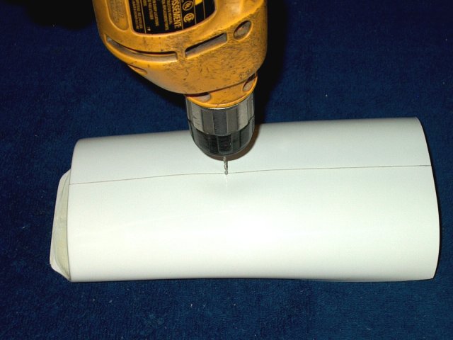
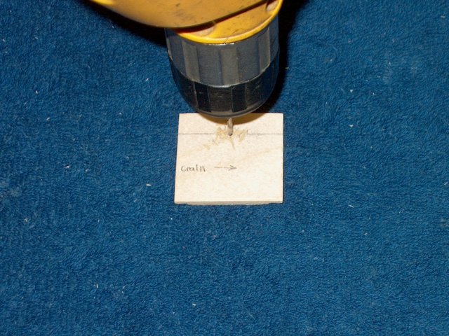
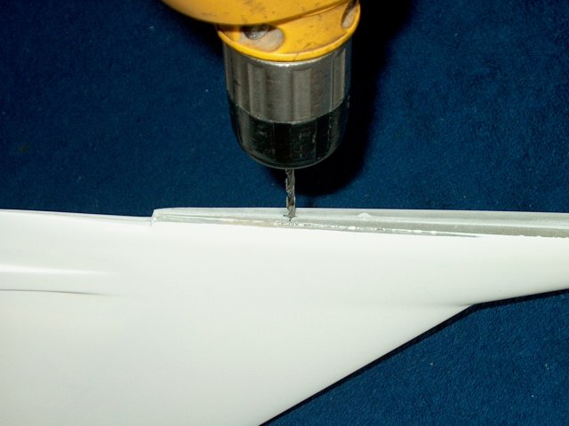
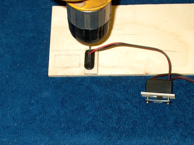
Drill the hole with a 5/64" bit
| |
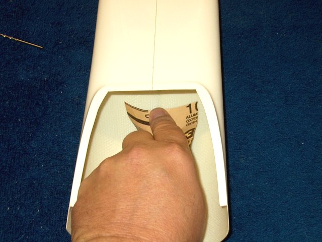
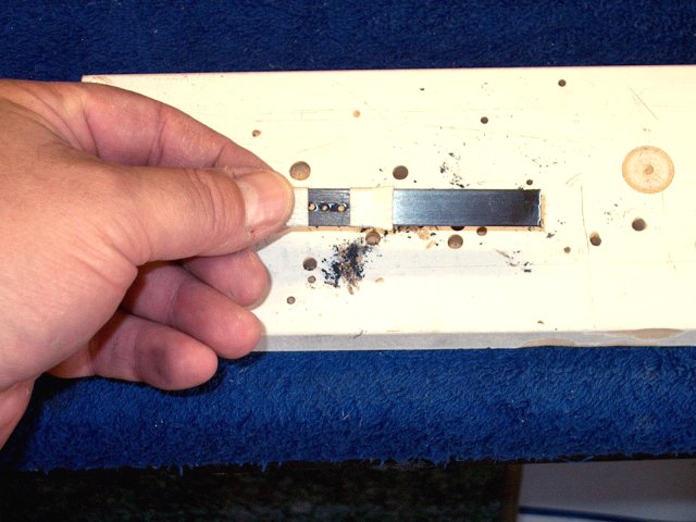
Rough up the inside area for the towkhook
plate with some 60 grit sandpaper | |
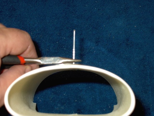
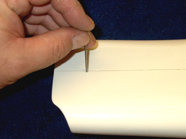
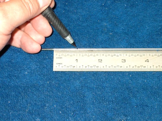
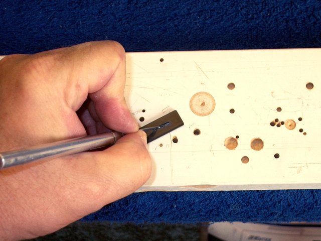
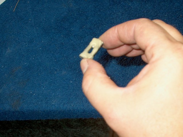
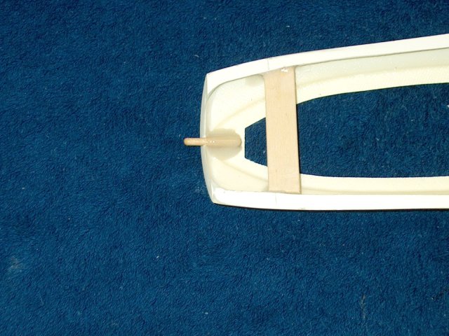
Make a towhook as shown using 2-56 steel
rod | |
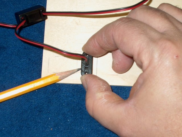
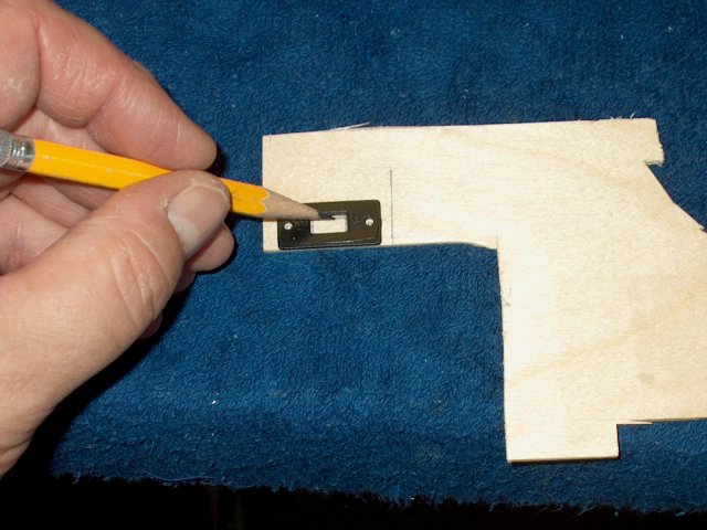
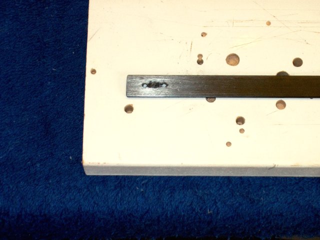
Mark a drill hole with a punch centered on
the two ply pieces and 10mm from the front edge
| |
Drill the hole for the towhook
| |
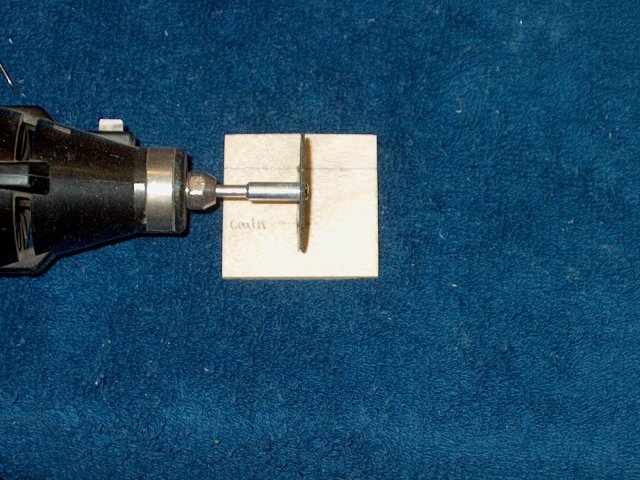
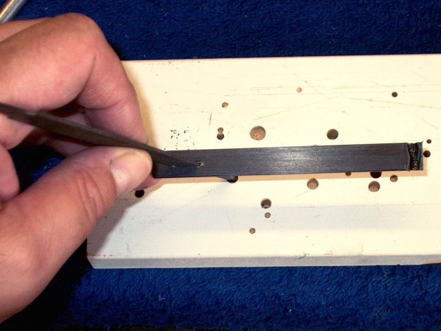
Use a dremel to slightly slot the area for
the towhook. Cut about 1/32" deep, just enough to prevent the
hook from twisting | |
Clean up the slot with a knife
| |
Use coarse sandpaper to rough up the hook
on the short side | |
Insert the hook in the ply
| |
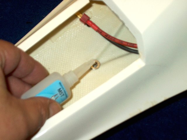
Use epoxy to glue the hook in place
| |
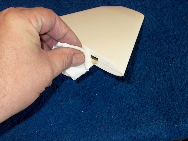
Slightly taper the outside edges to the
contour of the intake, then apply epoxy as shown
| |
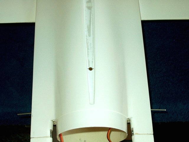
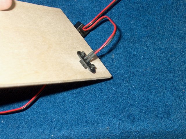
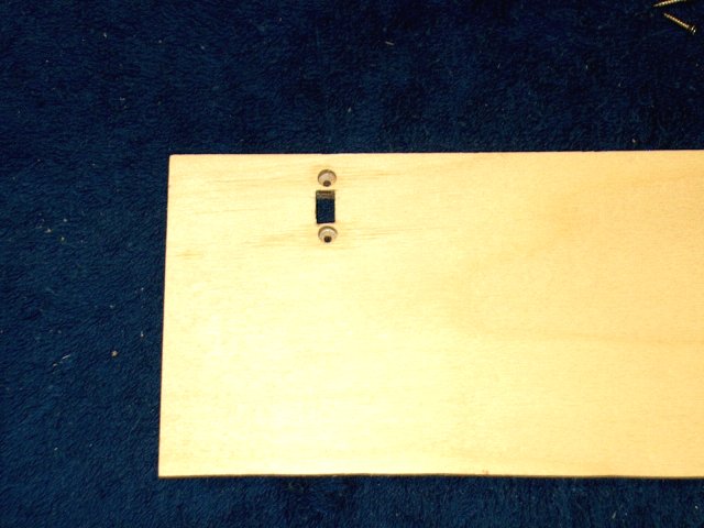
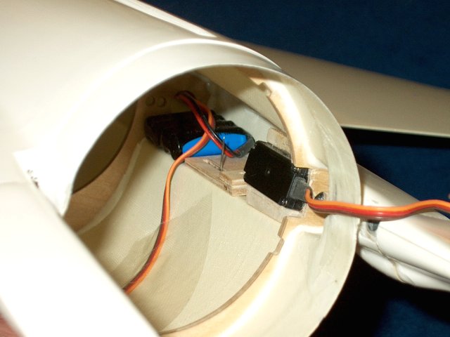
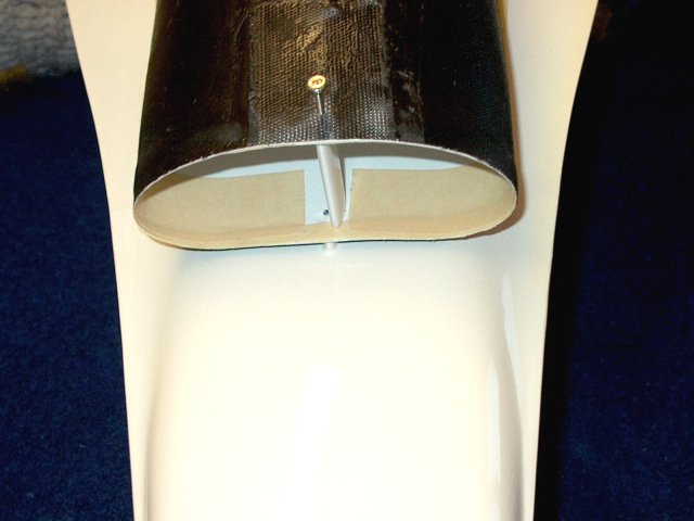
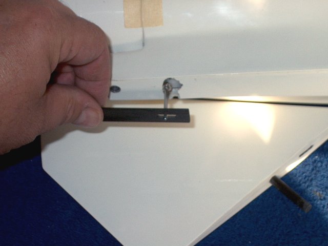
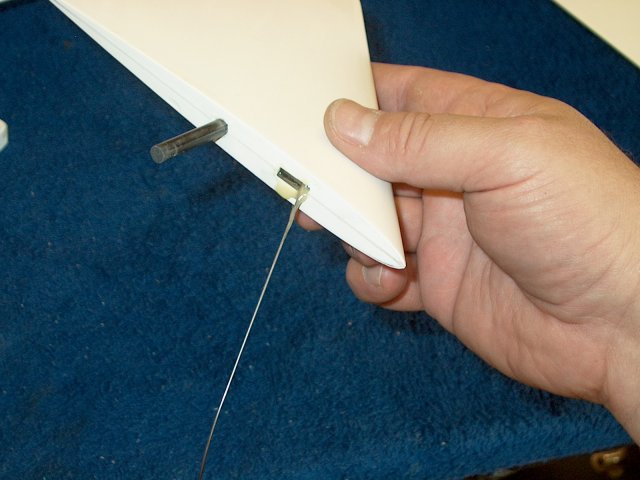
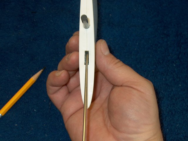
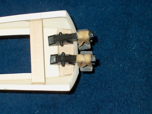
Install the towhook through the hole in
the intake and allow the epoxy to set. Note the orientation of
the plate with the 10mm of spacing at the front
| |
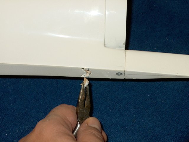
Use a pair of pliers to bend the hook into
shape | |
Mark the hook to a length of 3/4" and
remove the excess. Round the end with sandpaper
| |
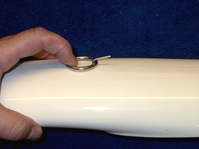
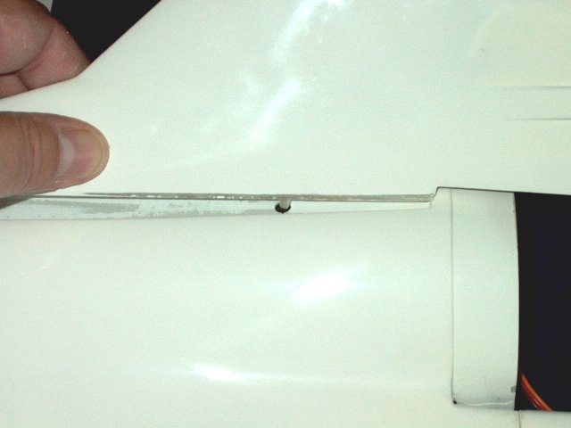
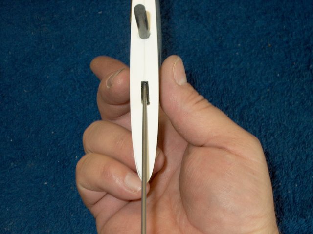
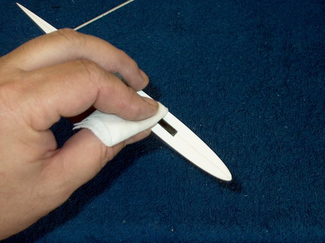
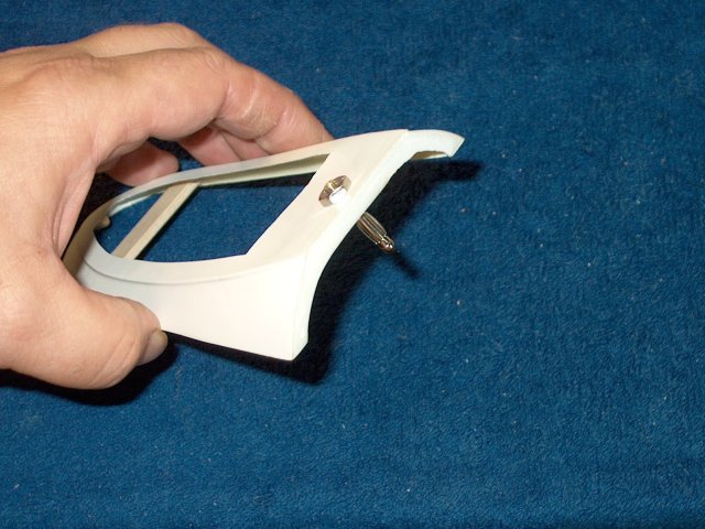
Check the clearance of your towhook ring,
then set the assembly aside | |
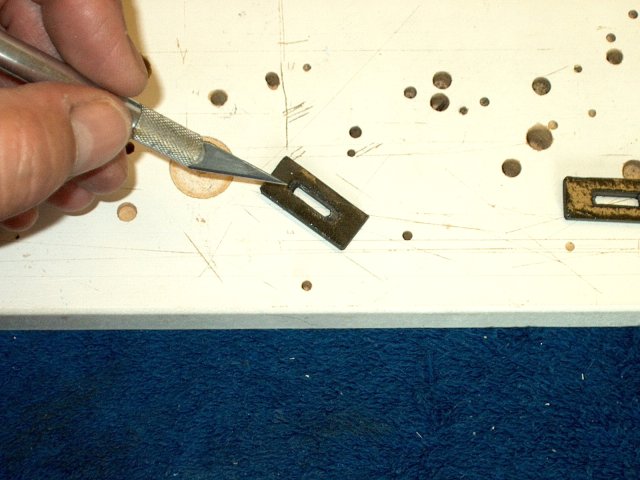
Use a dremel to cut out the notches in the
tail area of the fuselage | |
A file and sandpaper can be used to smooth
the area | |
A saw can also be used to cut and remove
the excess fiberglass | |
Use a small saw to cuth the Tail Brake
pieces in half | |
Sand and round the edges
| |
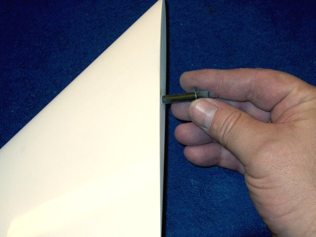
Use a drill to open up the holes for the
tailerons on both sides | |
Custom cut the tail of the brake so it
fits arouns the taileron shaft, then apply epoxy to the
area | |
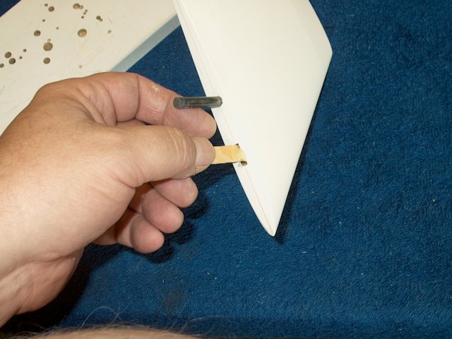
Apply epoxy to the shaft lip and install
flush to the fuselage | |
Make sure it is recessed completely and
even with the outside. | |
Custom fit the second brake
assembly | |
Apply epoxy to the hole and brake, then
glue it in place | |
Tape the piece to hold it straight until
the glue cures | |
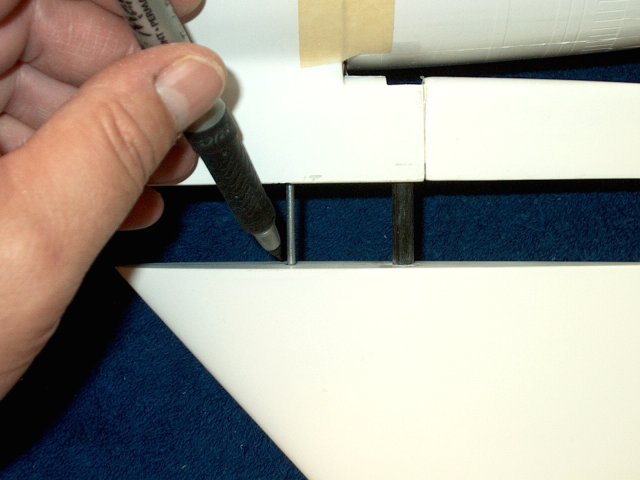
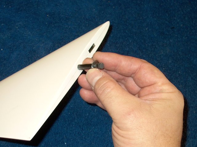
Install a Taileron, then mark a cut line
with a saw | |
Remove just enough of the shaft so there
is enoguh for the wheel collar to hold
| |
Sand the end and remove all ridges
| |
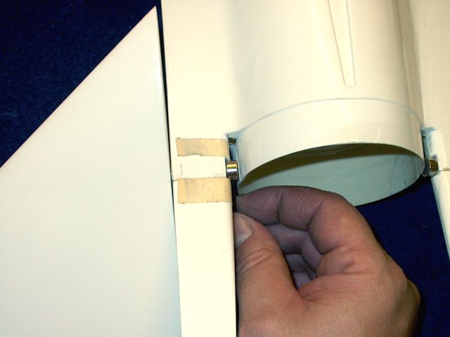
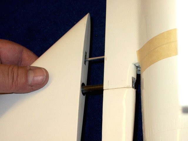
Install the taileron and wheel collar,
then mark the outer locations of the wheel collar on the
fuselage with masking tape | |
Use a file to notch the area, so the
collar is far enough away from the exhaust area so it doesn't
rub | |
Fine sand the area
| |
Install the supplied washer
| |
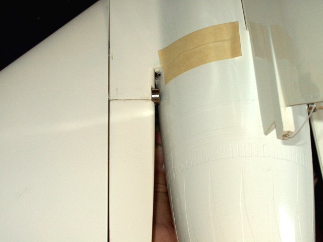
Install the Wheel collar, holding the
taileron to the fuselage side. Remove and sand the shaft until
it is flush with the inner part of the collar
| |
Final fitting completed, you will have
space between the collar and Exhaust nozzle
| |
Notch the other taileron shaft
| |
Shorten the shaft the same as the
first | |
Make sure to remove any ridges on the
inside of the taileron | |
Sand the shaft and round the end at the
edges | |
Install the taileron and wheel collar,
then use masking to mark the outer sides of the collar
| |
Once again, use a file to notch the wheel
collar area. It should be wide enough to allow the wheel
collar to turn without binding. | |
Install the second washer
| |
Install the wheel collar over the shaft
and tighten | |
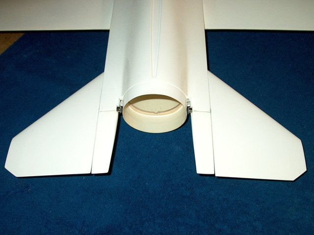
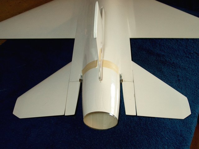
Taileron mounting completed
| |
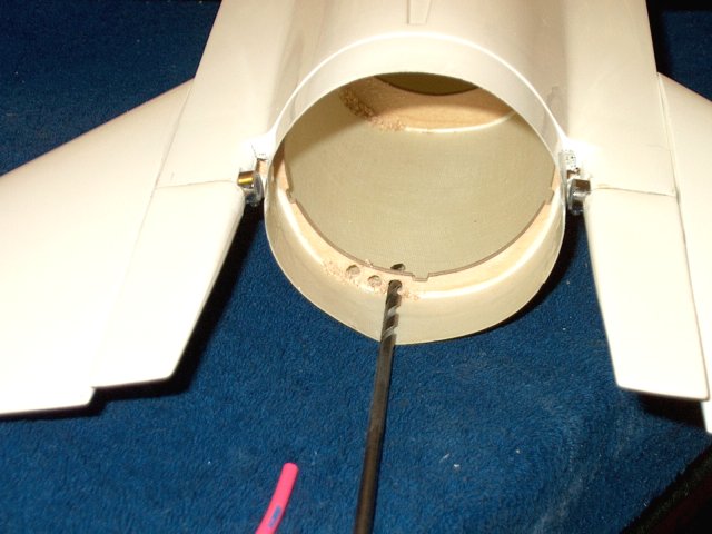
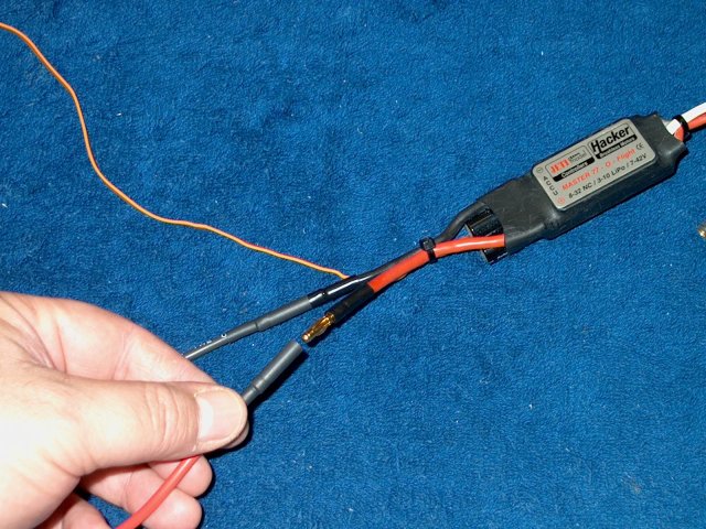
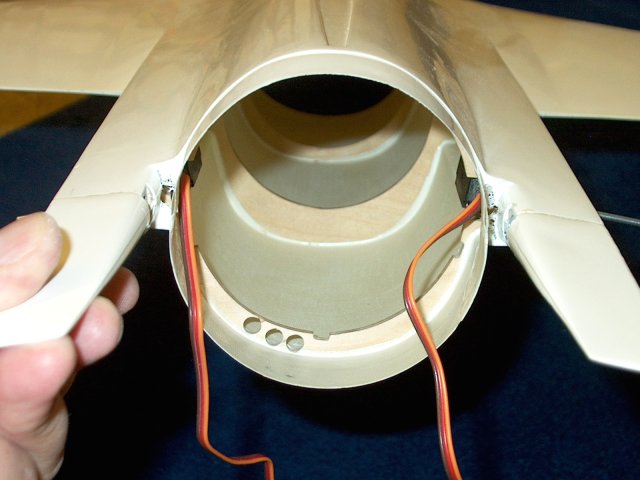
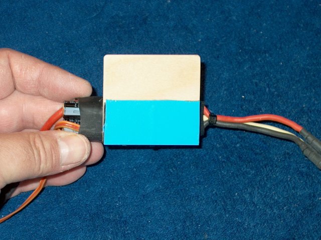
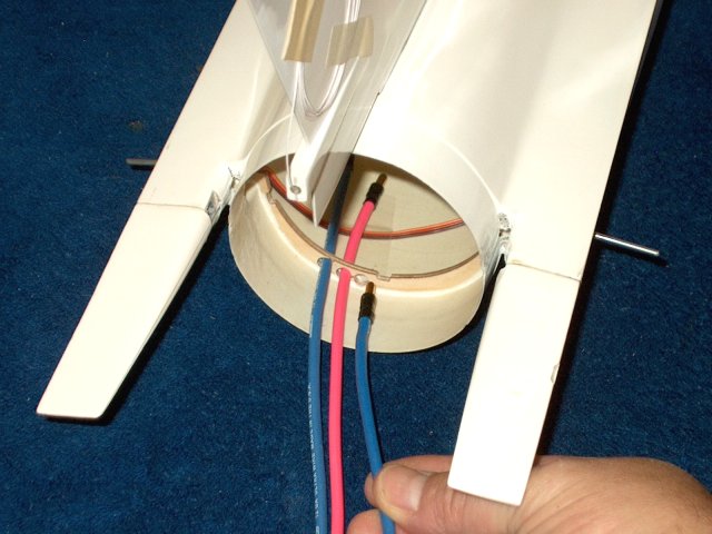
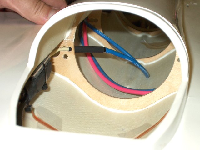
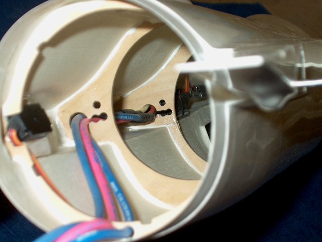
Drill three holes for the motor to ESC
wires as shown | |
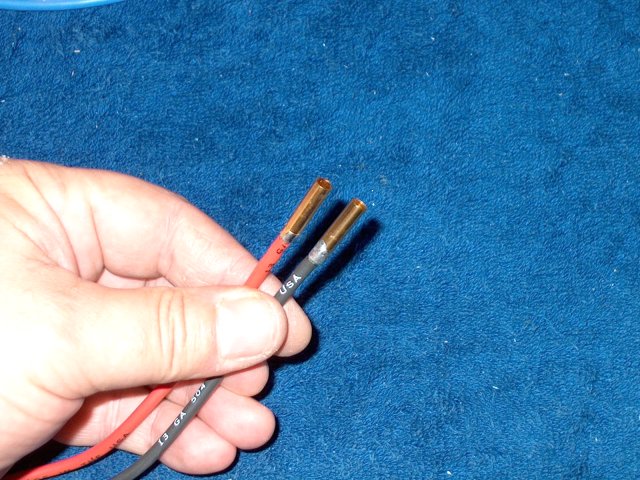
Solder ends to the 12ga wires that will
plug into the motor | |
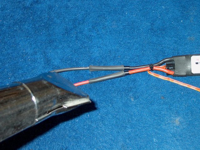
A piece of 1/64" ply is cut 3/4" wide to
make an airfoil for the wires | |
The ply is inserted into the heat shrink
and just fits | |
Solder plugs for the ESC side to the
wires | |
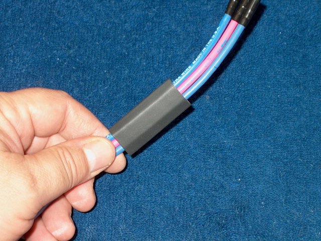
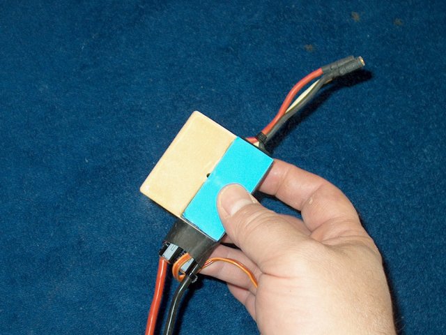
Slide the airfoil over the wires as
shown | |
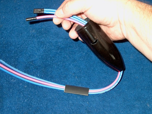
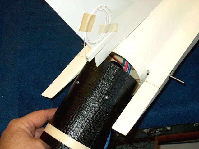
Run the wires through the Carbon fiber
motor cover that was supplied with the motor assembly
| |
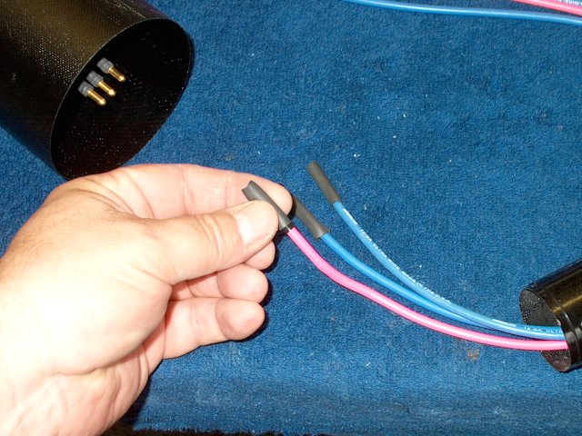
Slide pieces of heat shrink over the motor
wires | |
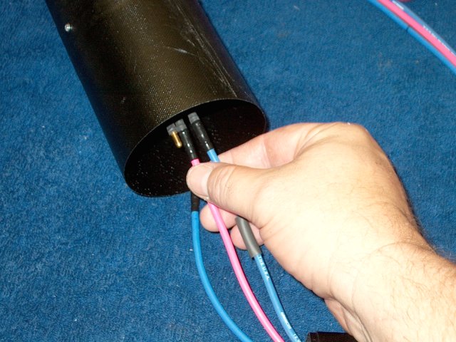
Install the wires on the motor
connectors | |
Slide the heatshrink in position, then use
a heat gun to shrink the tubing in place
| |
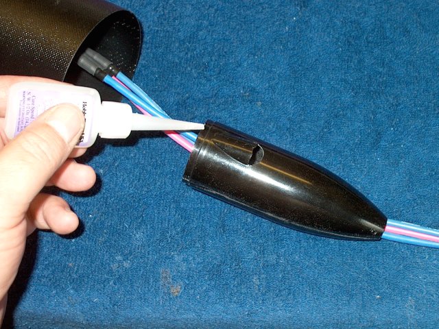
Apply some thick CA to the lip of the
motor cover | |
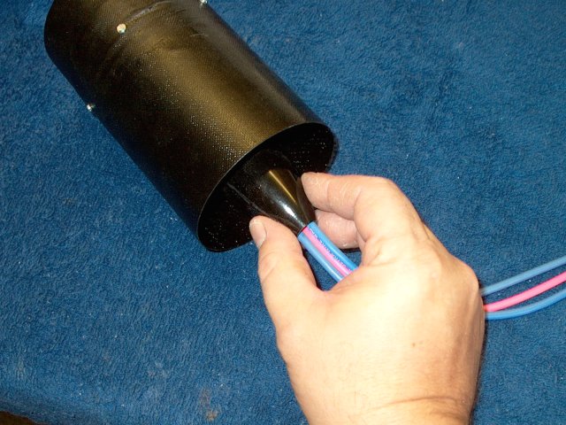
Install the cover in the motor
housing | |
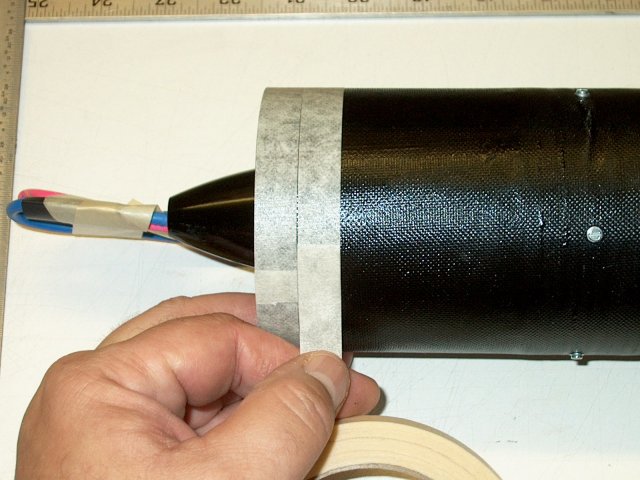
1/2" tape is applied to the rear of the
motor housing to build up the area around the former
| |
Remove the outer spacer tape
| |
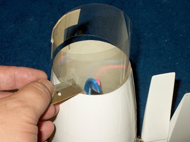
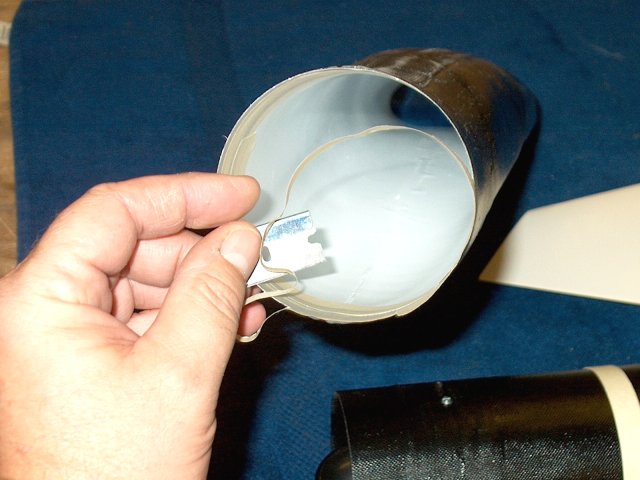
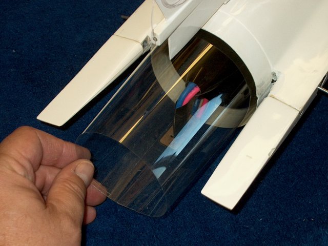
An Exhaust Duct is made from clear
mylar | |
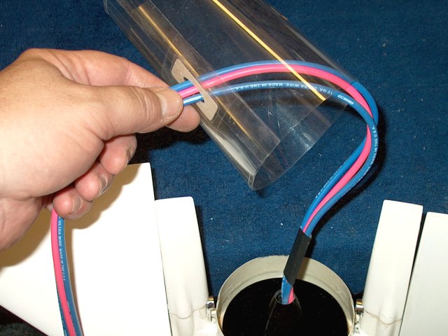
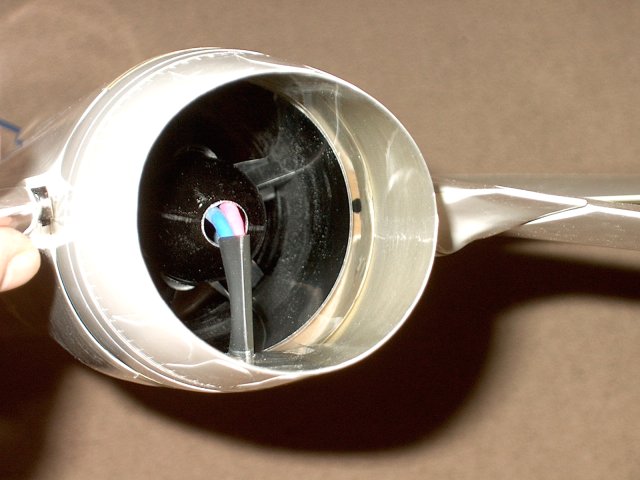
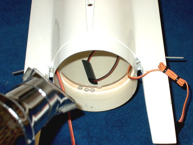
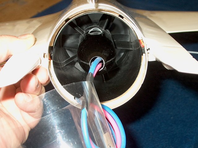
Temporarily tape up the motor wires and
run them down through the fan so they are out of the wya, then
shape the duct | |
Tape the Nozzle flush to the rear of the
fuselage. Make sure the mylar duct fits well to the rear of
the Exhaust Nozzle | |
Trim away any excess material with a
razor | |
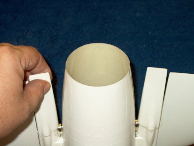
Duct should be flush to the rear and note
that the wheel collars should clear the nozzle
| |
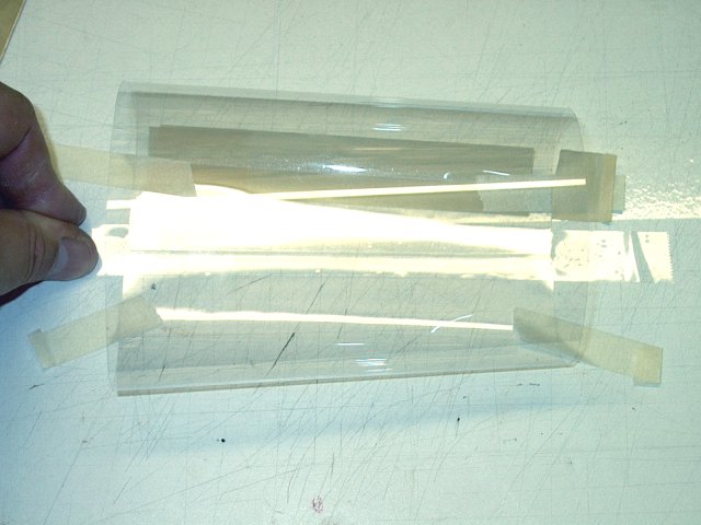
Use 1" strips of packing tape to seal up
the inside of the duct | |
Tape the outside of the duct as well with
a 1" wide strip | |
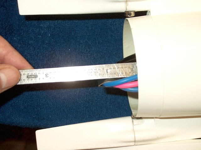
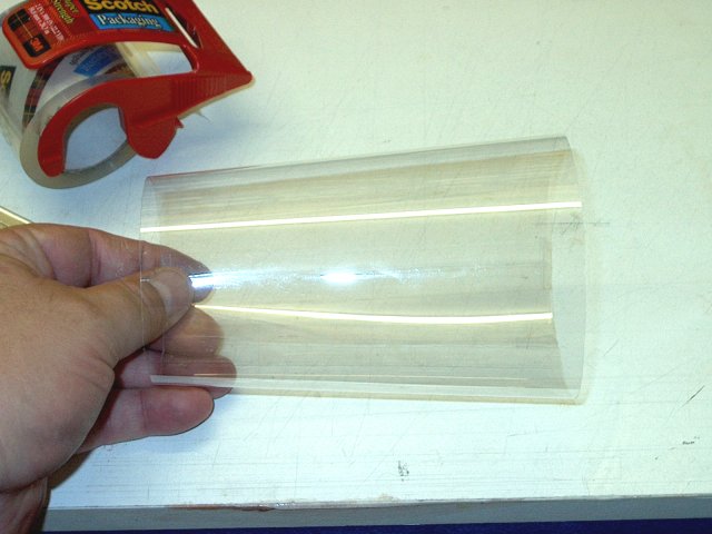
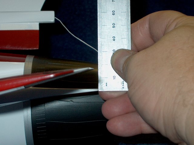
Measure the distance from the end of the
fuselage to the rear of the motor cover
| |
Make amark on the duct at this distance.
Note you will cut rearward from this mark for the airfoil to
exit | |
Make a small plate from 1/64" ply for the
airfoil as shown | |
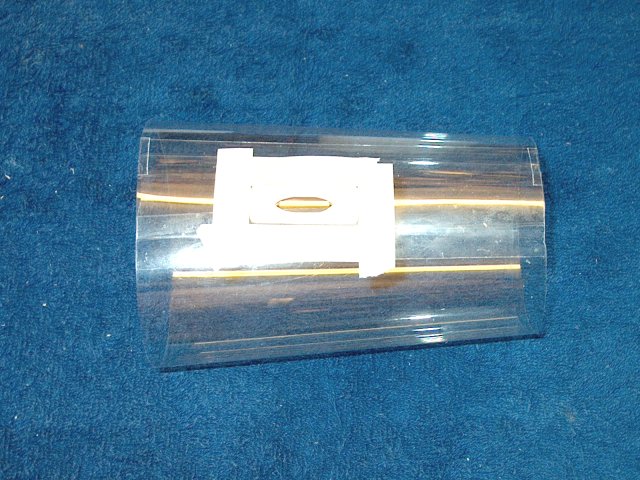
Mark the area with tape, then cut the
airfoil at the thick side of the duct, where it overlapped.
Glue the plate in place with CA or epoxy, then another piece
of 2" wide packing tape can be used to seal the plate to the
duct | |
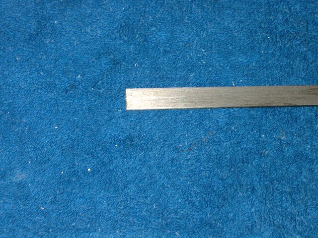
The airfoil was removed and the bottom was
tapered rearward to the andgle of the tapered mylar exhaust
duct | |
Install the airfoil, then run the wires
through the duct | |
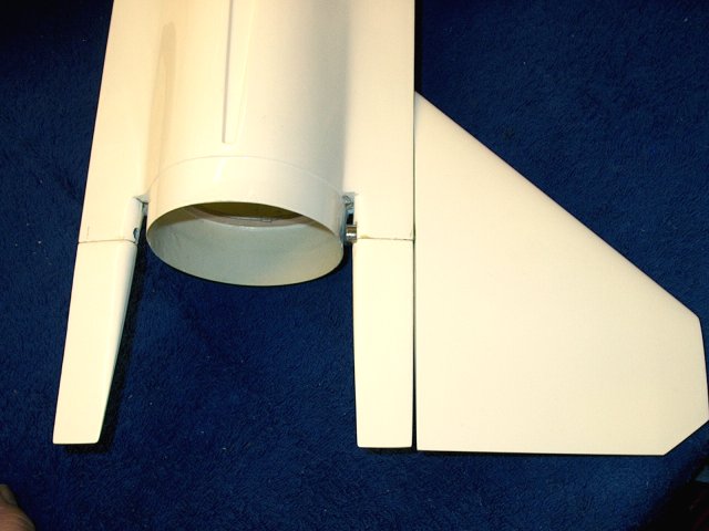
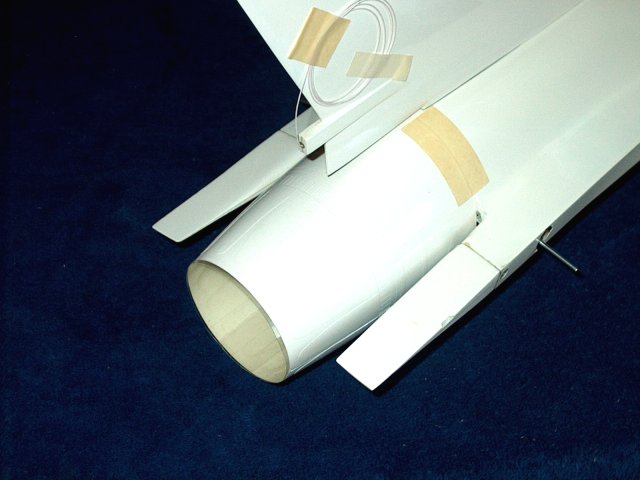
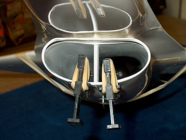
Test fit the assembly and adjust as
necessary. Shown is a fitted and assembled tail section
| |
Solder to 4mm sockets to the battery wires
for the ESC | |
Plug the wires into the ESC
| |
Use heat shrink to hold the wires in place
and prevent them from coming loose | |
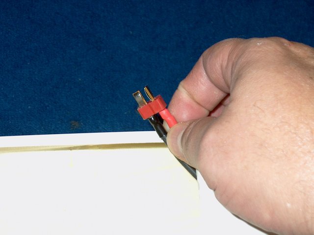
Solder a Deans Ultra plug to the other end
for your battery, or use any other plug that you use for your
power needs | |
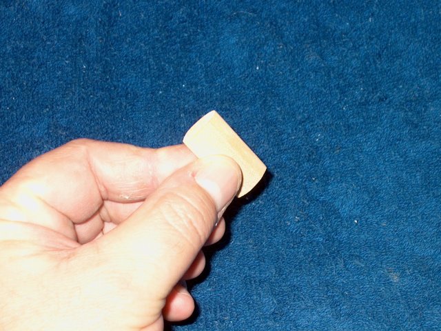
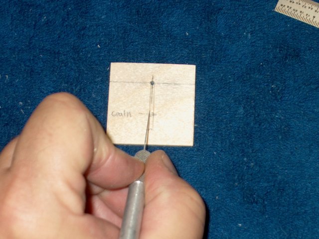
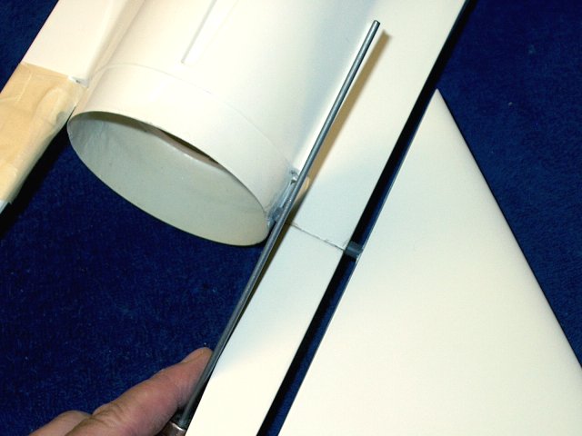
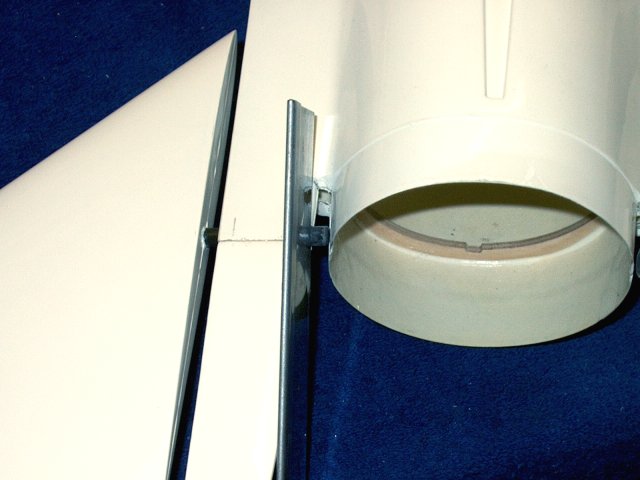
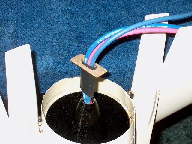
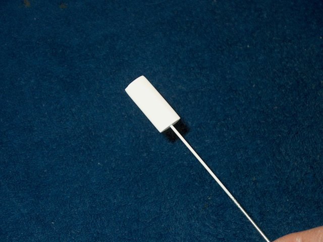
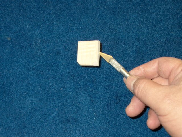
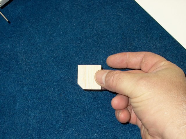
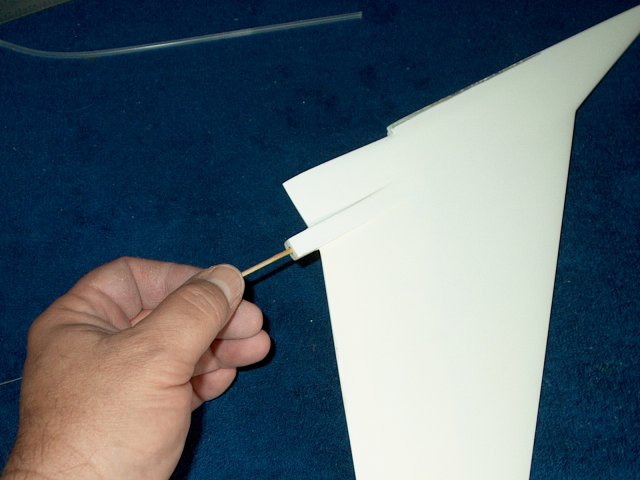
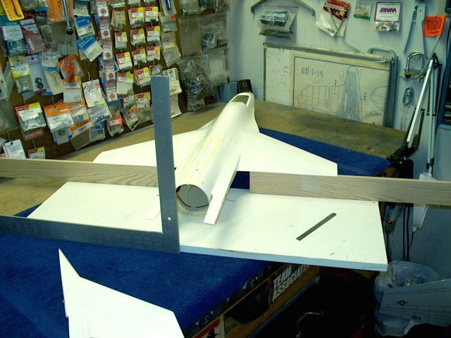
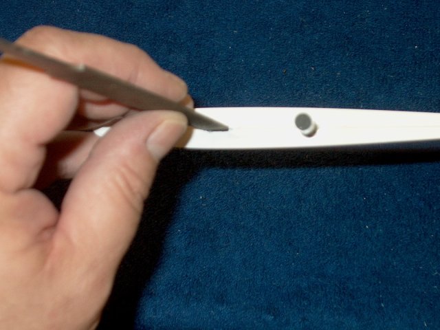
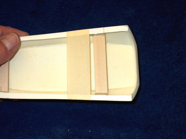
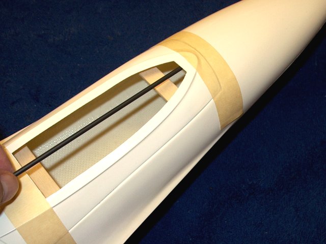
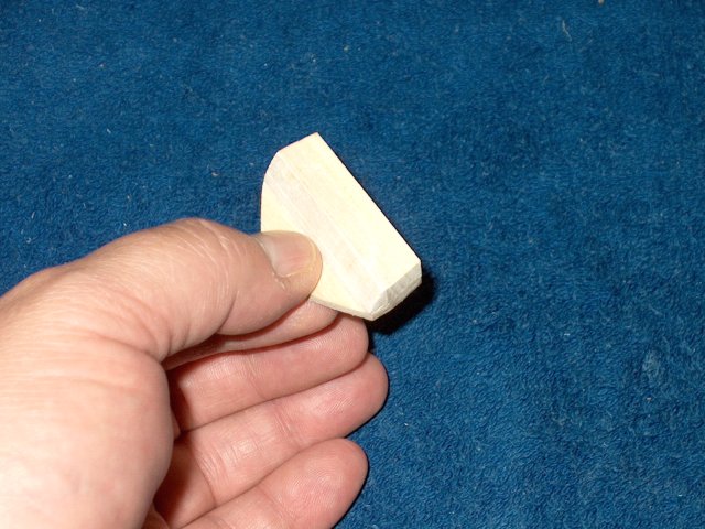
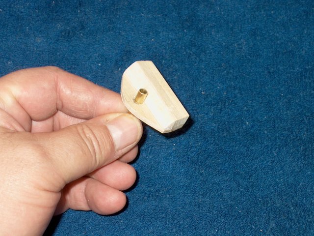
Make an airfoil from hardwood about 3/16"
thick and 3/4" wide. An old piece of wooden Helicopter tail
rotor blade was used and cut to shape as shown. It already had
a good airfoil shape to start and was long enough to act as a
spacer for the intake duct. CAREFULLY drill a hole straight
through the center length of the airfoil with a 5/64"
bit | |
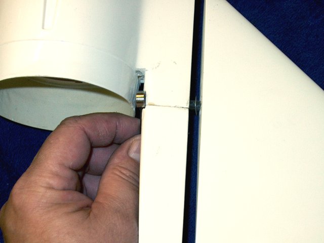
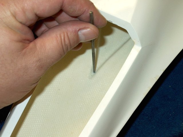
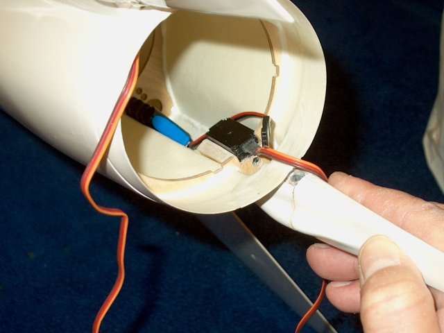
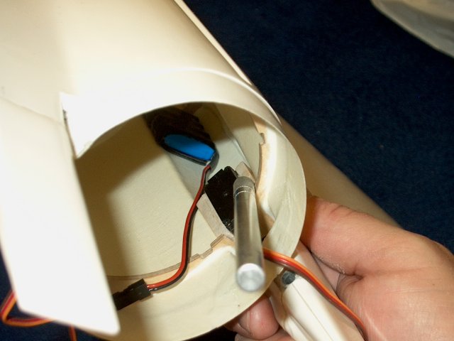
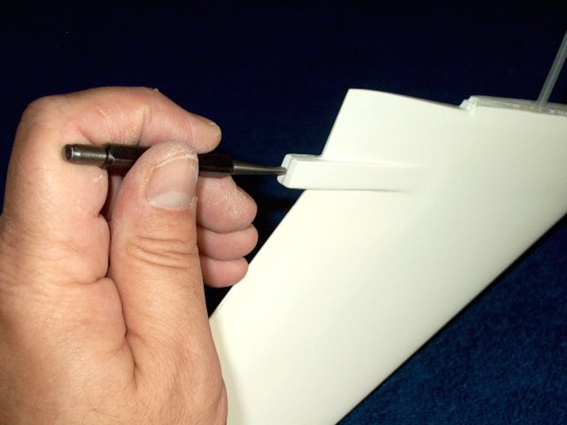
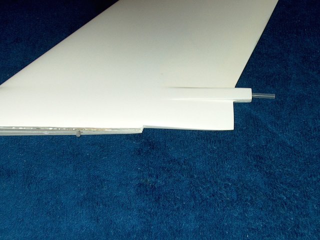
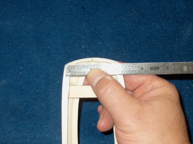
Drill a hole about 3/8" - 1/2" from the
front lip of the intake duct | |
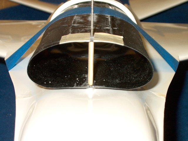
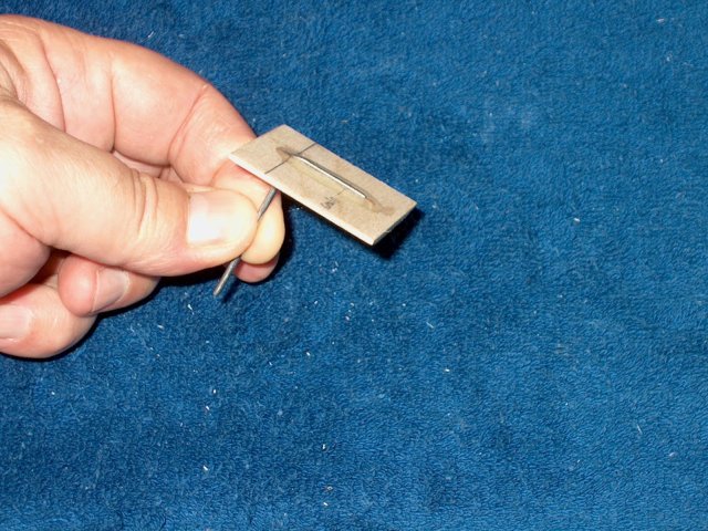
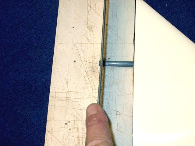
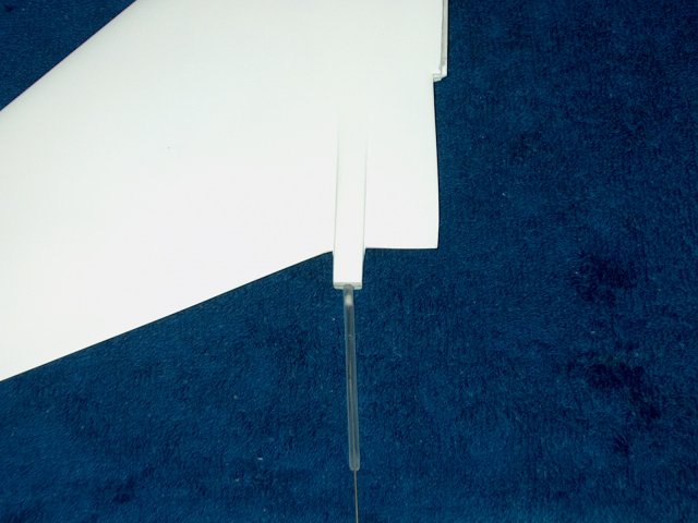
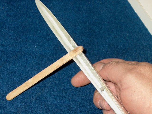
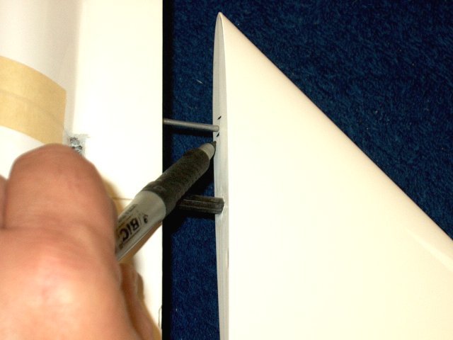
Position the duct, then drill a mark on
the other side, using the airfoil as a guide , which will hlp
you keep it visually centered. Sand the length of the airfoil
spacer so it matches the contour of the intake duct and fits
flush ont he top and bottom. it shoudl also fit without
deforming the shape/opening of the intake
| |
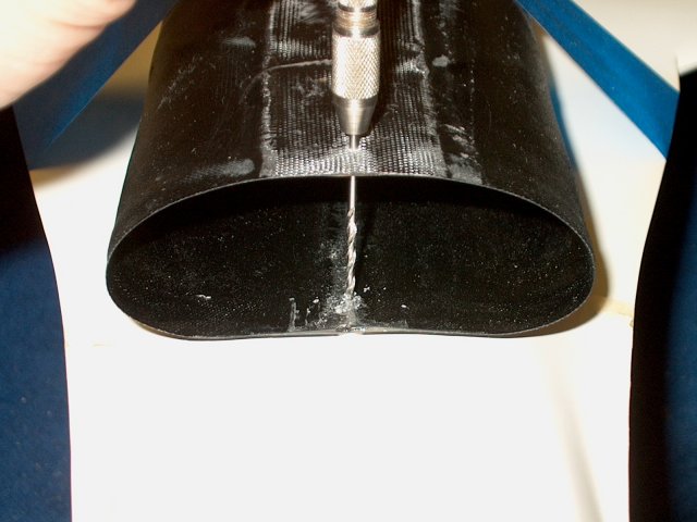
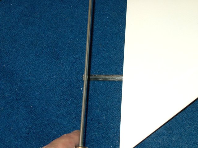
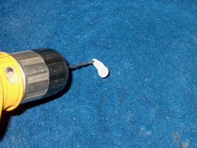
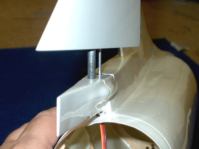
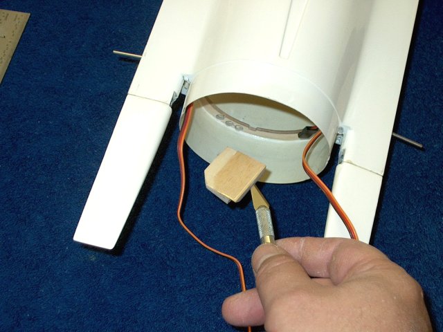
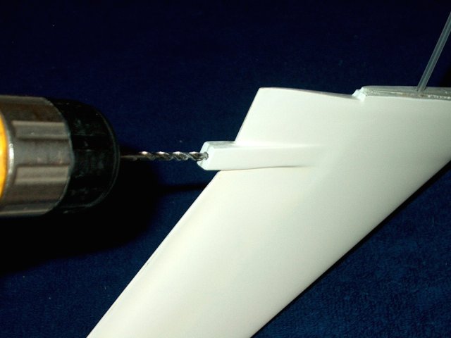
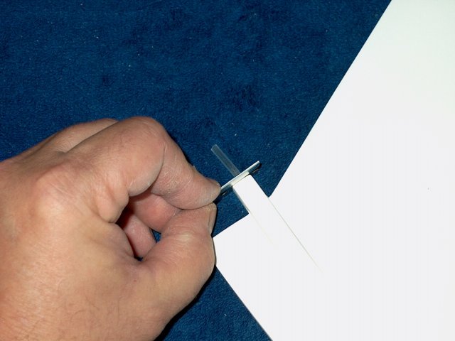
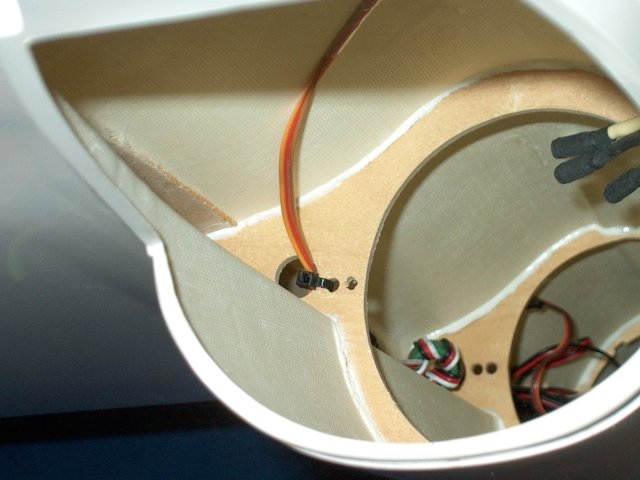
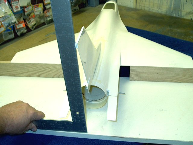
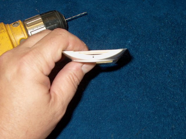
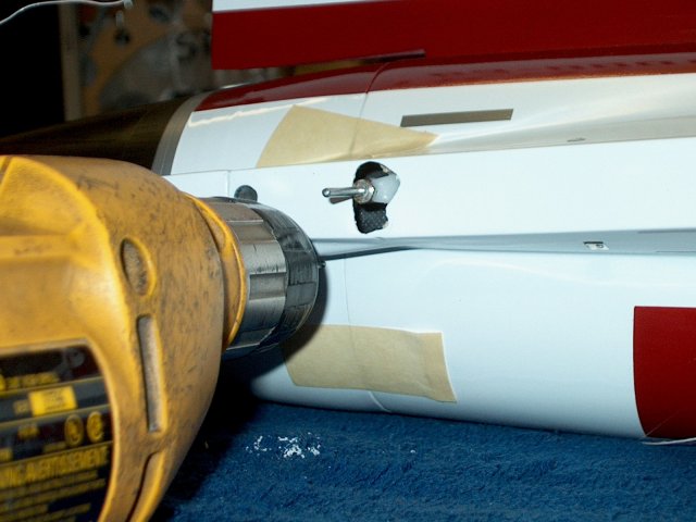
Use a hand drill to finish, drilling
through the duct and fudelage | |
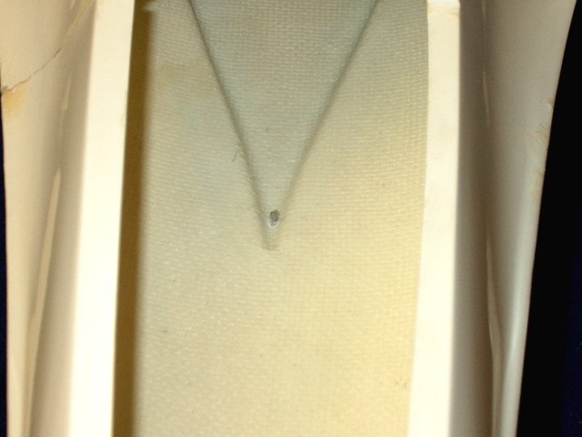
Hole throught he fuselage is shown. This
will also help with alignment during final assembly and gluing
and also strengthen the ductwork | |
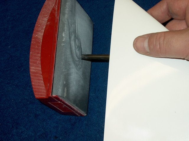
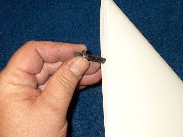
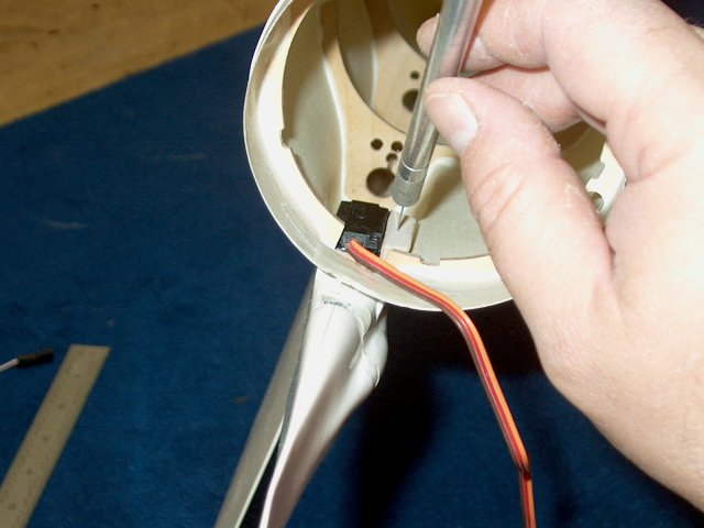
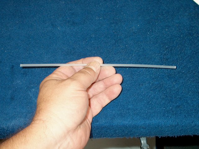
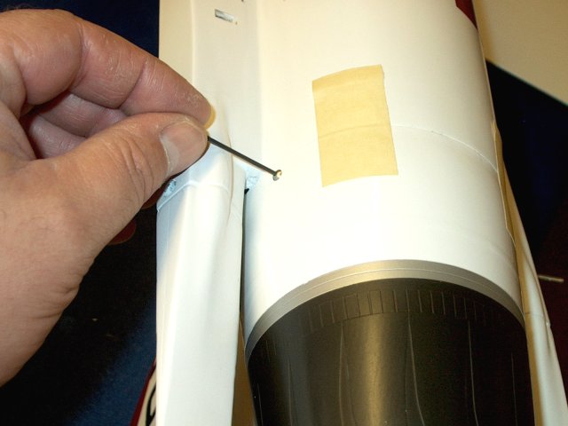
A small file was used to slightly open the
hole so 2-56 threaded rod can pass through
| |
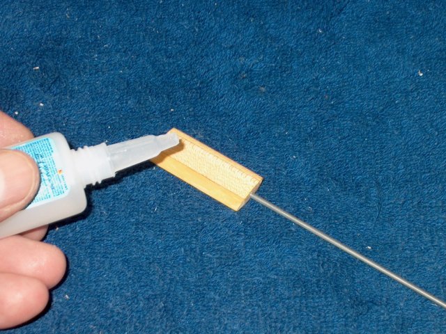
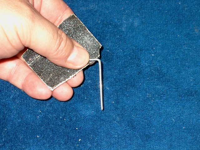
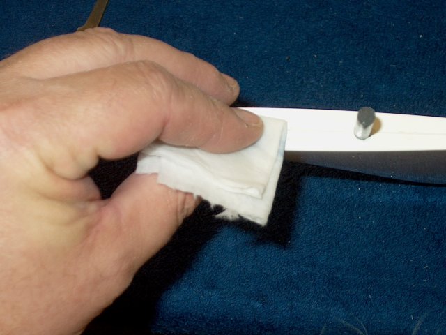
The airfoil is covered with CA to seal the
wood | |
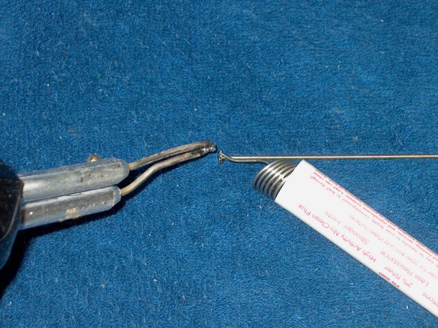
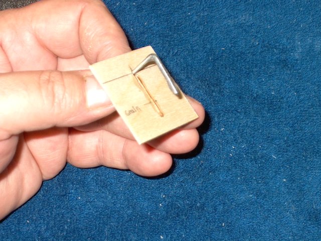
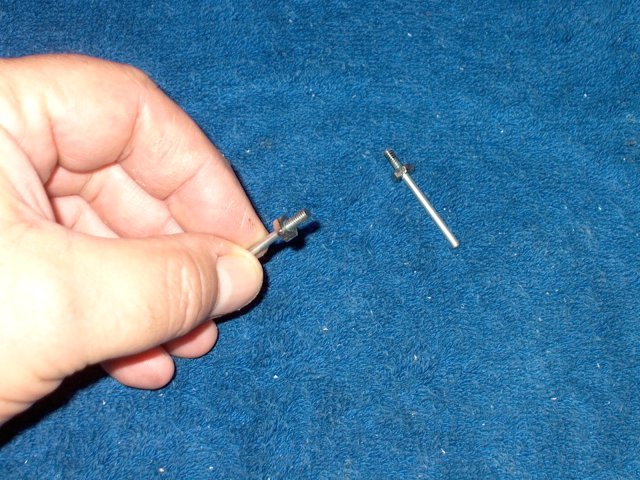
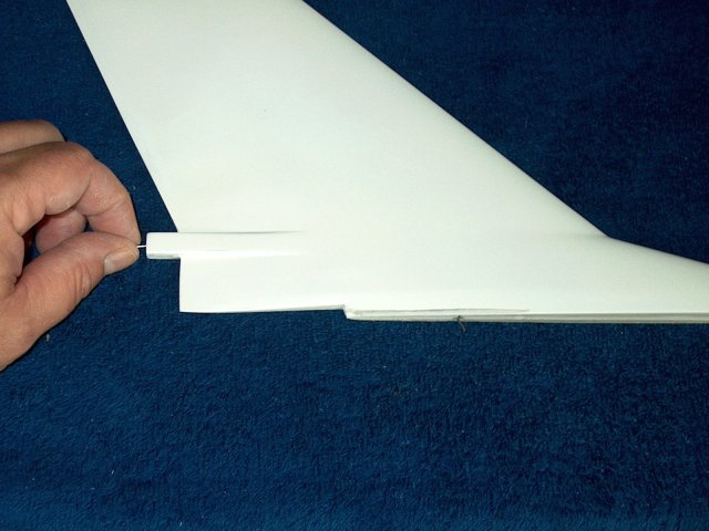
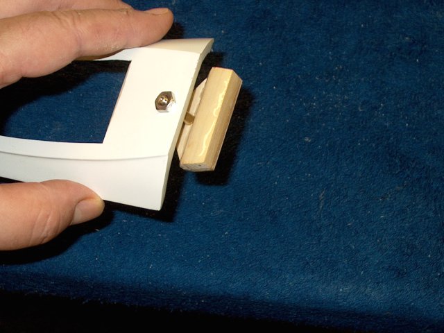
A 2-56 nut is soldered flush to one end of
the allthread rod | |
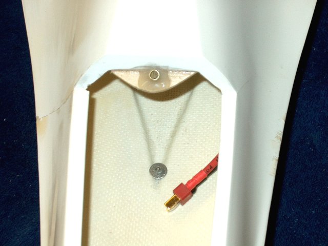
The rod is installe dthrough the duct into
the fuselage, then marked to trim. Allow enough length for
spacers and lock washer/nut | |
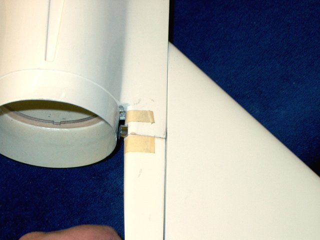
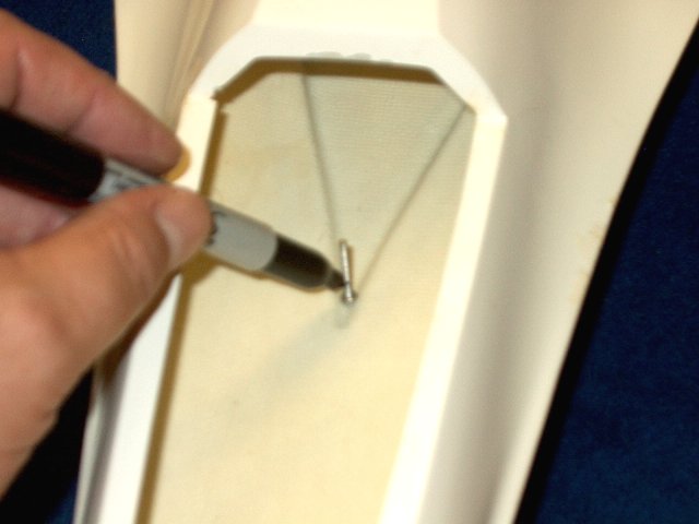
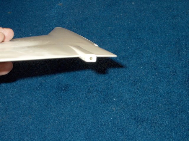
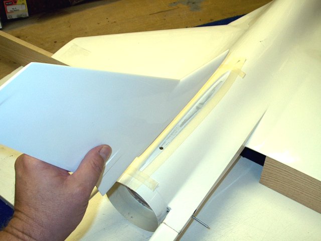
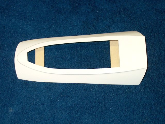
Install the fiberglass intake. Align it
and tape the intake in place | |
Drill through the hole in the fuselage and
into the intake | |
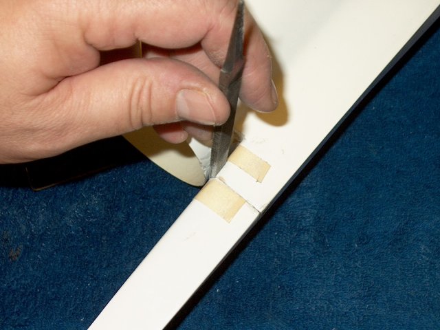
Remove the intake and file the hole so the
2-56 rod fits | |
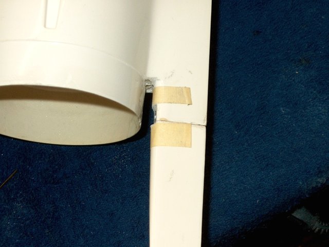
Hole shown drilled through only the top of
the fiberglass intake and through both sides of the carbon
fiber duct | |
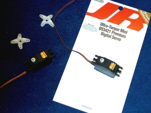
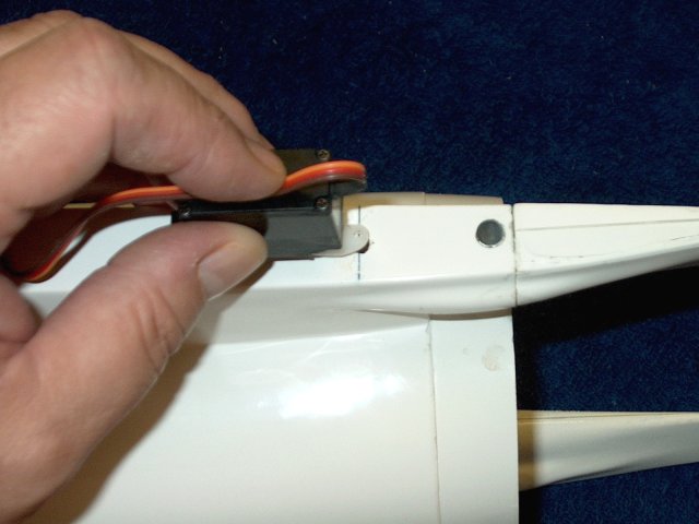
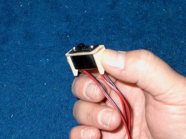
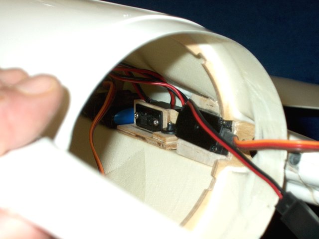
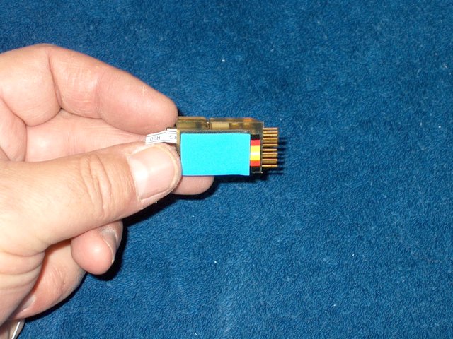
JR DS3421 metal gear servos are used on
the tailerons. These are the ONLY recommended servos as their
low profile makes them the only ones that fit
| |
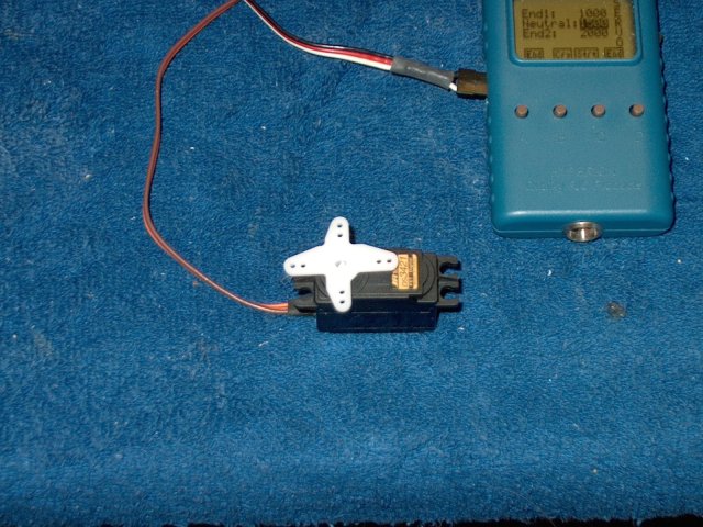
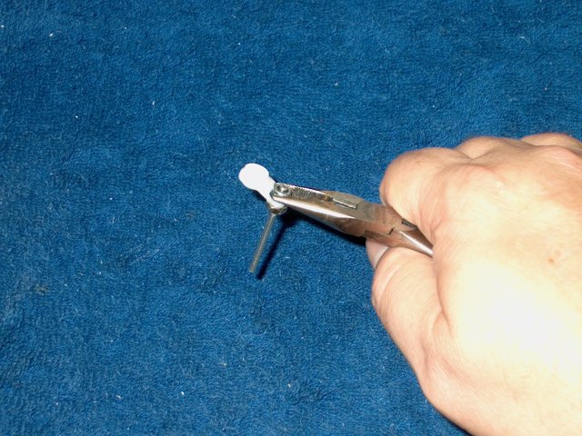
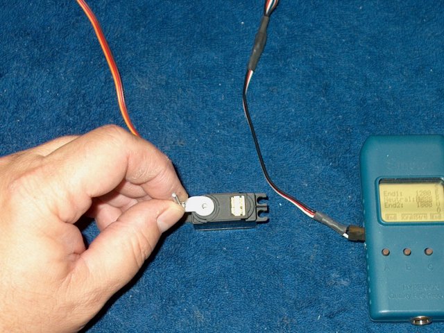
Use a receiver or servo tester to center
the servo, then install the horn | |
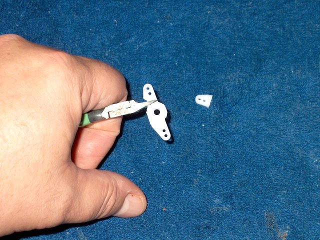
Trim away the unused sides from the
horn | |
Trim the mount from the wire side that is
closest to the servo output gear | |
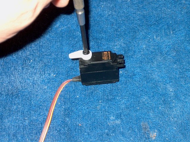
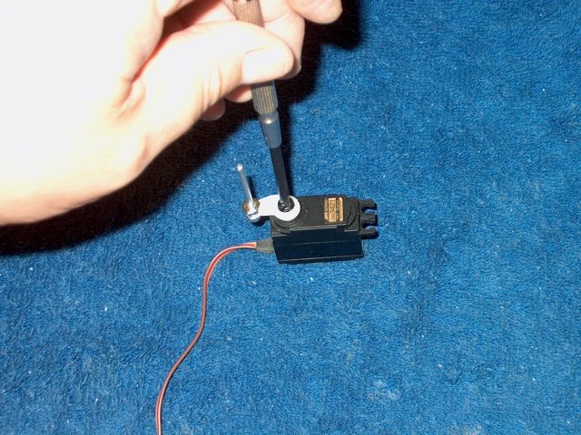
Center the servo, install the horn and
install the retaining screw | |
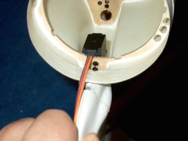
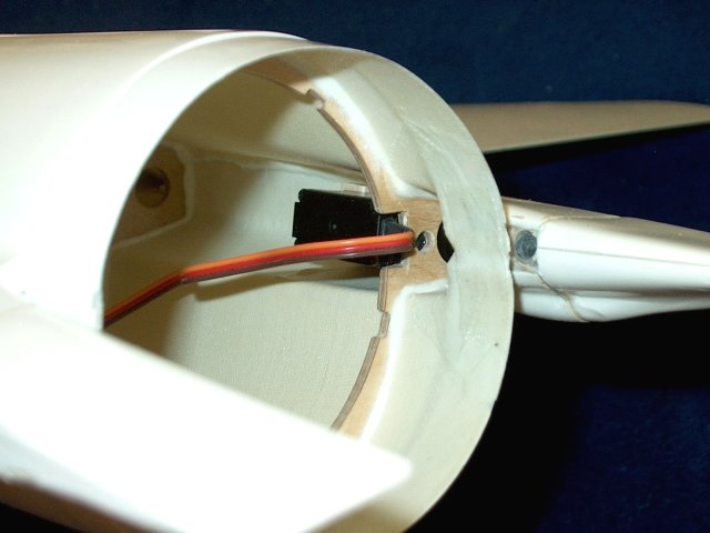
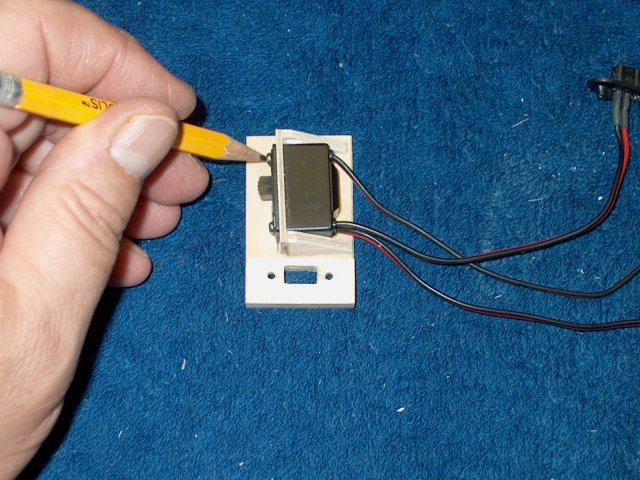
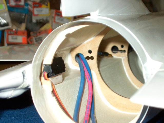
Poaition the servo in the fuselage, then
mark the former for wire clearance | |
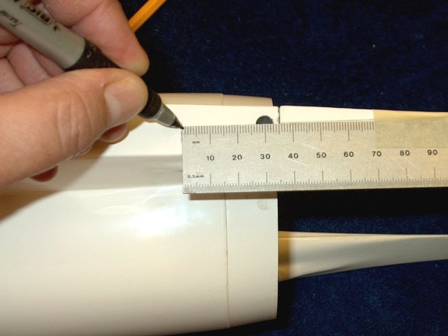
Mark the side of the fuselage 30mm in
front of the center of the tailron shaft
| |
Mark the location with a punch
| |
Drill a pilot hole a tthe mark
| |
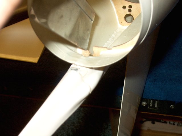
Use a saw to remove some of the former on
the inside so the wire passes through while the servo fits
flush against the inside wall of the former
| |
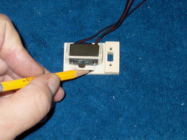
Center the servo and check the outside
hole | |
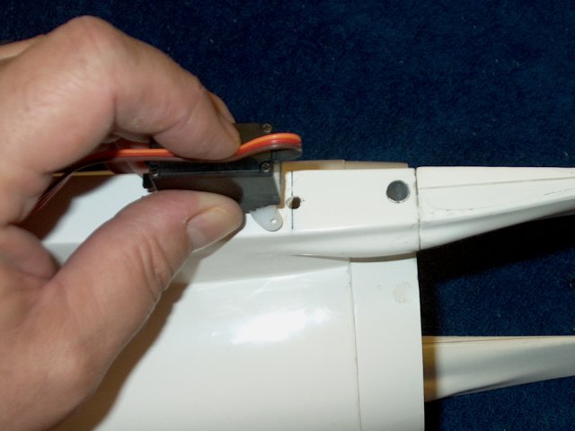
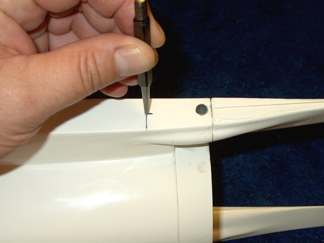
Pivot the servo to the end side of the
fuselage and make a mark | |
Draw a line showing the movement area of
the srvo horn | |
Use a punch to mark the end points
| |
Drill each end point, then carve between
them | |
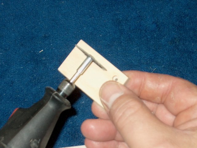
This was the most difficult part of the
build. The former is right in the middle of where the servo
arm should be and the slot needed enlarged enough to remove
the former pieces, from the outer wall to about 3/8" deep.
Cutting and grinding with a dremel router made the job
easier | |
New tailron pushrods were made from 4-40
rod | |
Cut the rod to length
| |
Drill the outer hole for each rod
| |
Install a top nut flush to the inner side
of the threads and rod | |
Install a nylock nut on the other
side | |
Center the servo and reposition the
horn | |
Install each horn screw
| |
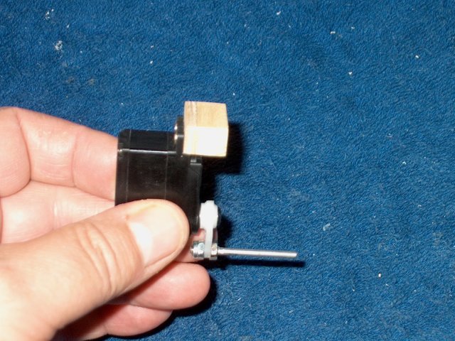
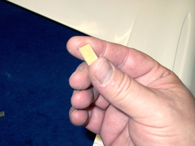
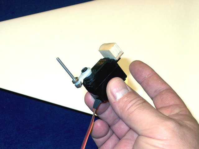
A 1/2" wide x 3/8" thick hardwood block is
cut 3/4" wide ans screwed to the servo
| |
Screws on the bottom side of the servo are
shown | |
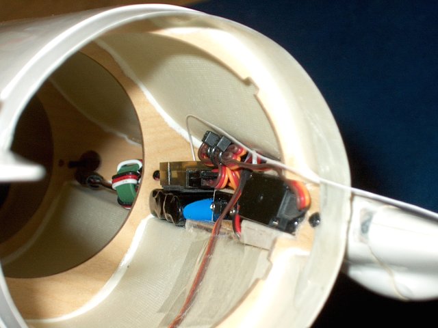
Apply epoxy to the top of the block and
the side of the servo by the wire, then install it in the
fuselage. NOTE... pay close attention to alignment and check
for correct position before gluing the servo
| |
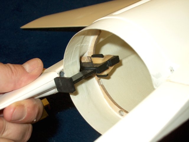
The servo must be positioned so the
pushrod is perpendicular to the fuselage
| |
Important: Not only must it be aligned to
the fuselage, the servo must run at a parallel downward angle
to the taileron. You will need to install a taileron and
check, then hold the servo in place while the glue sets. For
these reasons, 5 minute epoxy is recommended
| |
Servo is shown with wire side glued to
inside of former and the wood block is glued to the outer wall
slot (located behind servo) | |
Another Important Note! Both sides of the
fuselage were not even...one side had the former closer to the
taileron shaft hole than the other. You should space the
shorter side with a piece of ply between the inside of the
former and servo | |
Ply spacer was needed on the short side,
where the former was closer to the taileron shaft hole. This
insured that both servo pushrods would be equally spaced from
their respective taileron shaft holes
| |
The second servo is glued into place, the
same as the first | |
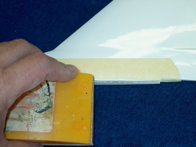
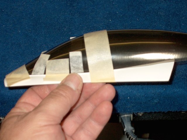
The intake duct was taped and primed, then
painted prior to completing the build
| |
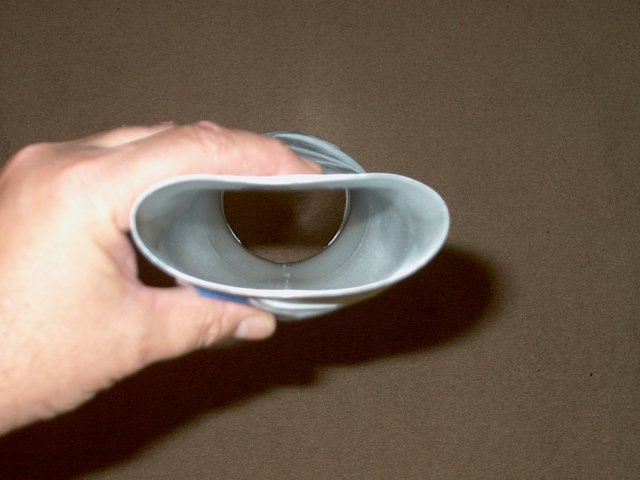
Photo shows intake primed first, then
sanded | |
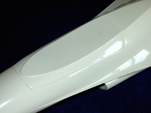
Intake painted with gloss white
| |
The spacer airfoil was also painted
| |
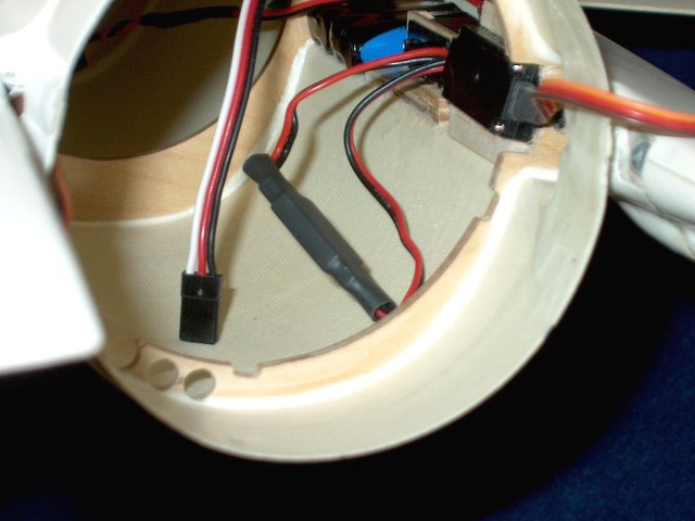
The rear of the inside area was cleaned
with an alcohol pad | |
Apply two layers of servo tape to your
receiver | |
Install your receiver battery or BEC as
shown. A 2/3AAA 400mah NiMH pach was used for this model and
it weighs about the same as a U-BEC
| |
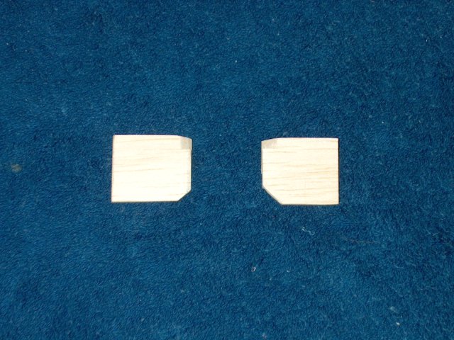
Make wedges for the servos on the top and
bottom by cutting a couple pieces of 3/16" thick balsa to
shape | |
Apply epoxy to each wedge
| |
Install them in place on one servo
| |
Apply epoxy to the second wedge
| |
Install the wedge on the bottom for the
other servo | |
Cut two more wedges for the top
| |
Apply epoxy and install each of the two
balsa wedges on top of the servos | |
Rough up the edge of the Vertical
Stab | |
Sand the shelf for the vertical
stab | |
Make a mark in the stab well 3" from the
rear of the model. This will be for the antenna. Note that
this is only one method of installing the antenna
| |
Transfer the mark from the fuselage to the
bottom of the stab | |
Mark the location with a punch
| |
Drill a 1/8" hole for the antenna
tube | |
Mark the rear center of the fin as
shown | |
Drill a 1/8" hole for the antenna
tubing | |
Cut about 9" of antenna tubing
| |
Bend a small pushrod wire so it curves
down and passes through the bottom hole
| |
Slightly round the end of the antenna tube
so it passes through easily | |
Check the antenna tubing run and make sure
you have enough length for your guide rod
| |
Apply some epoxy in the rear hole with a
toothpick | |
Install the antenna, working it to the
bottom center of the stab using the wire as a guide. A piece
of paper towel along with a couple drops of alcohol can be
pushed torugh to remove any epoxy the inside of the
tube | |
Allow the epoxy to set
| |
Trim the tubing flush with the end of the
stab | |
Antenna tube installation completed
| |
Use a punch to mark a hole for the antenna
tube exit | |
Drill a 3/16" hole for the tube
| |
The oversized hole will allow for easier
installation | |
Check the fit and make sure the tube
clears the hole | |
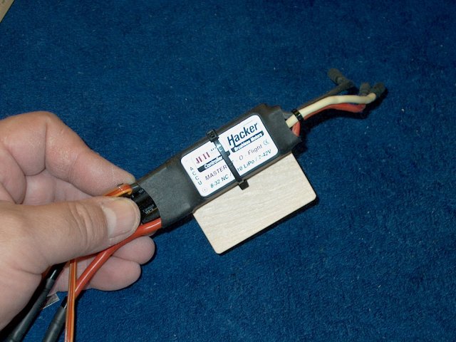
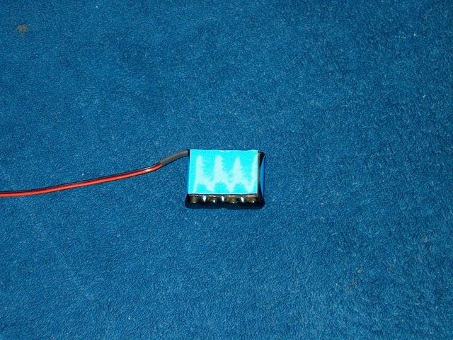
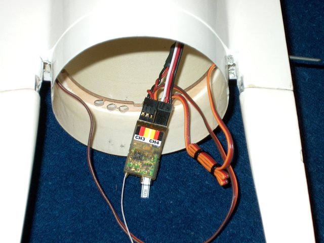
A small plate was made from 1/16" ply to
hold the ESC. The ESC is mounted to the plate and tied in
place | |
A piece of servo tape is added to the
bottom of the ply under the ESC | |
Apply epoxy to the other half of the plate
| |
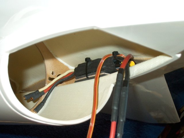
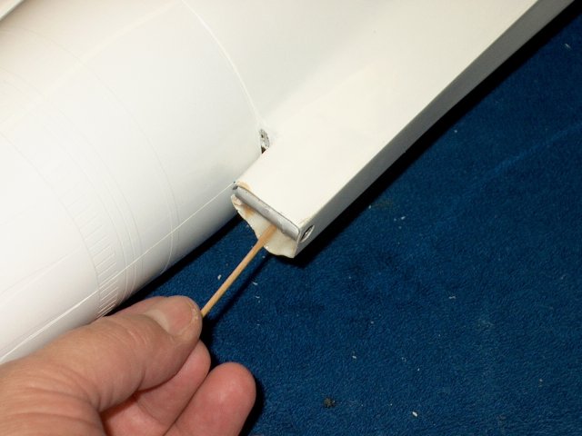
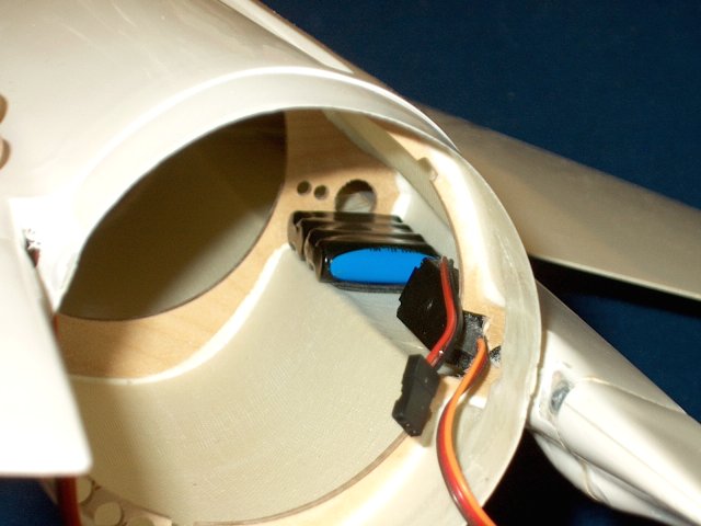
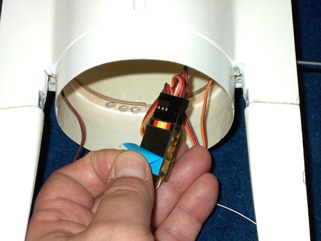
Install the ESC inside the fuselage as
shown | |
A wood dowel can be used to hold the ply
plate to the wing sheeting until the epoxy cures
| |
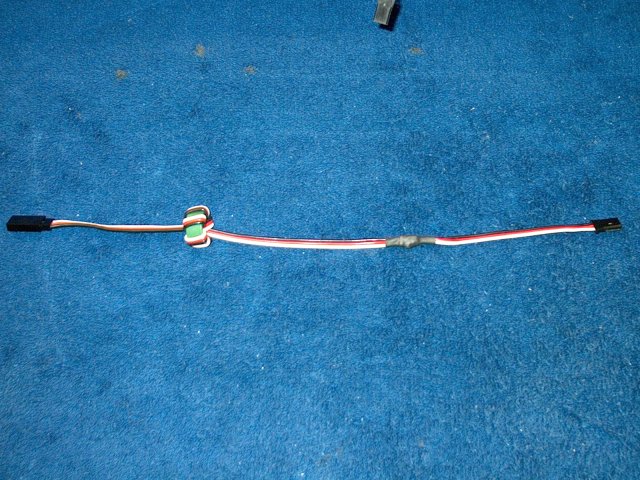
A 18" servo extender is wrapped on a balun
and should be about 12" long when finished
| |
Feed the extension through the hole from
the rear and plug it into the ESC and use heat shrink to
insure it does not come apart | |
Make sure the servo wire run is on the
opposite side of the fuselage, away from the ESC wires
| |
Tie wrap the excess servo wire from the
right side servo | |
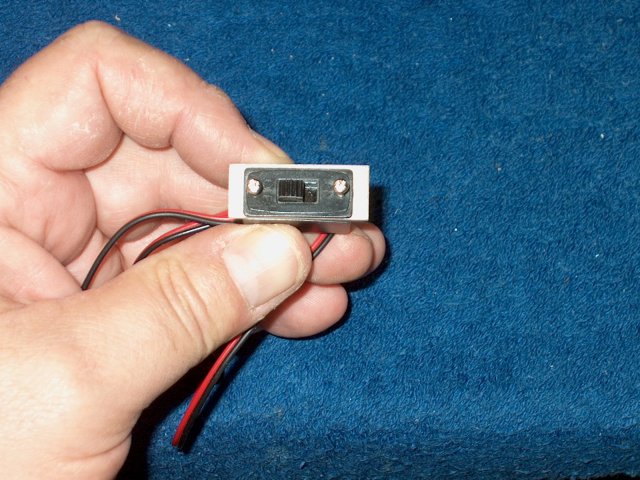
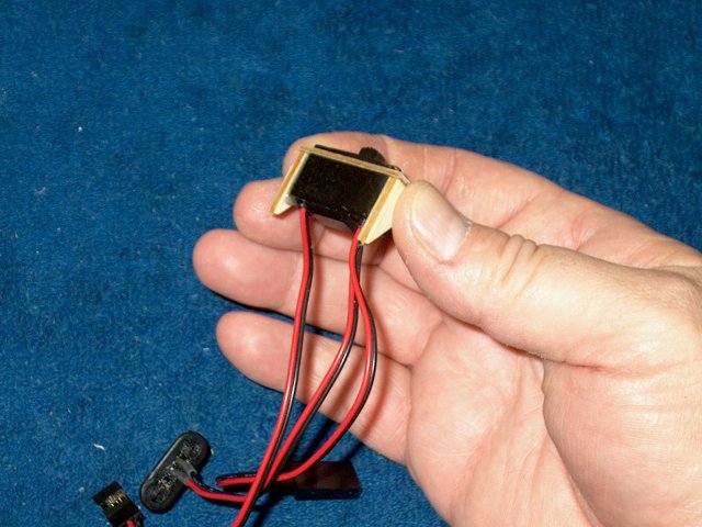
A Deans charge jack is installed on the
radio switch | |
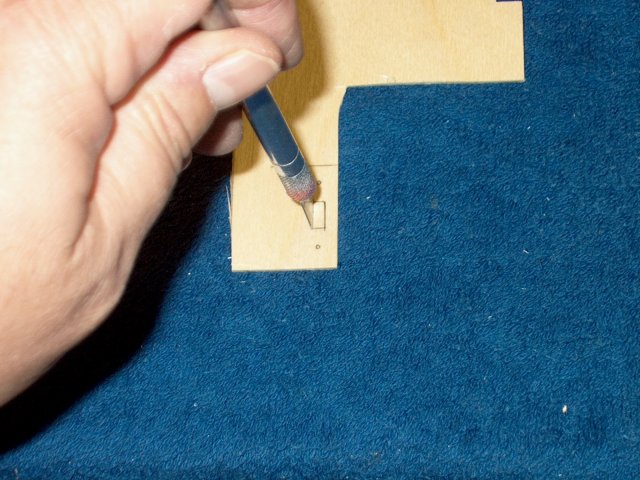
A switch mounting board is cut from 1/8"
ply | |
Transfer the shape of the switch to the
board | |
Also transfer the shape of the charge jack
to the board | |
Pattern is shown drawn on the ply
| |
Use a chisel Exacto to cut the slot for
the charge jack | |
Check the fit of the jack
| |
Transfer the switch plate slot to a piece
of 1/32" ply | |
Cut the switch hole in the plate with a
chisel knife | |
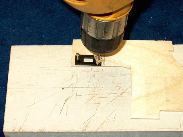
Drill the mounting holes for the
switch | |
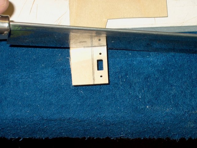
Cut the mount plate for the switch
| |
Check the switch for fit
| |
Cut a spacer for the charge jack from 1/8"
ply | |
Glue the ply spacer to the board over the
jack hole as shown | |
Install the jack and drill two small holes
for mounting screws | |
Countersink the other side of the
holes | |
Install 1/8" ply side plates to the
switch | |
Position the switch and draw a line at the
front edge of the faceplate for the switch
| |
Draw a second line 3/32" in front of the
first | |
Cut a slot here so a 2-56 sized pushrod
will fit through the slot | |
Install the plate in the fuselage
| |
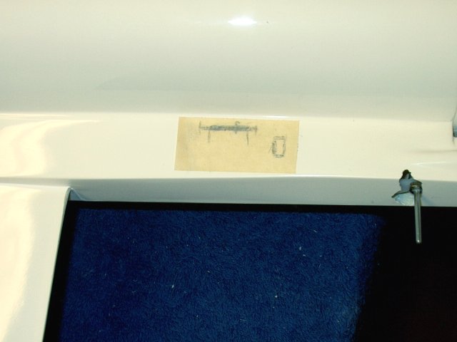
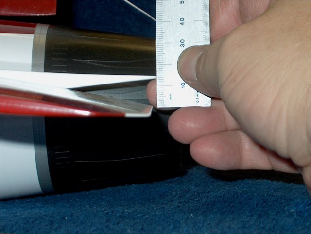
Measure from the front of the plate to the
rear of the fuselage | |
Draw a locator line on the fuselage
| |
Place the plate with its front at the
mark, then transfer the slot pattern to the fuselage
| |
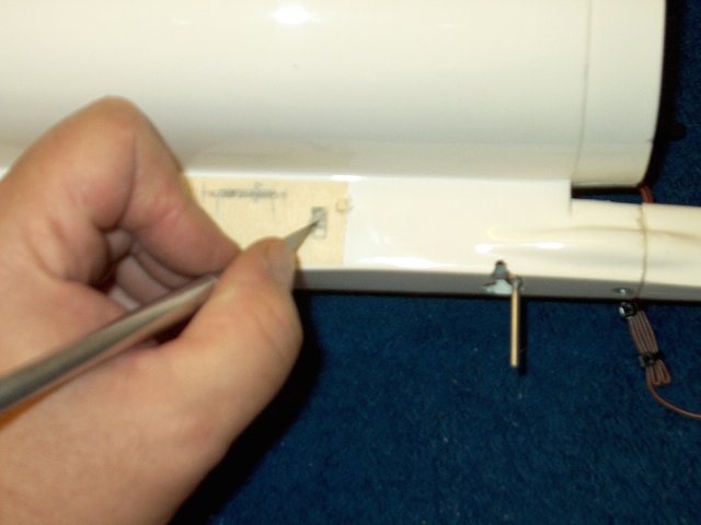
Install the plate in the fuselage, then
use a push pin to make sure you are centered
| |
Pin is shown exiting the slot
| |
Place strips of masking tape over the wood
on both sides of the slot and transparent tape over the slot
underneath, then apply candle wax to the slot and scrape away
the excess | |
Remove the tape from both sides. Apply a
piece of masking across the board, covering the slot and jack.
Trace the slot and jack position on the tape, then remov the
tape and set aside. This pattern will be used larter
| |
Apply epoxy to the frame of the
switch | |
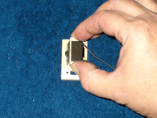
Install the switch in place and be sure
not to cover the slot | |
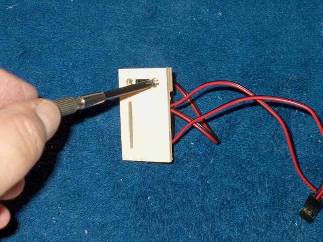
Install the retaining screws for the
charge jack | |
Apply epoxy to the board, but not in the
jack area | |
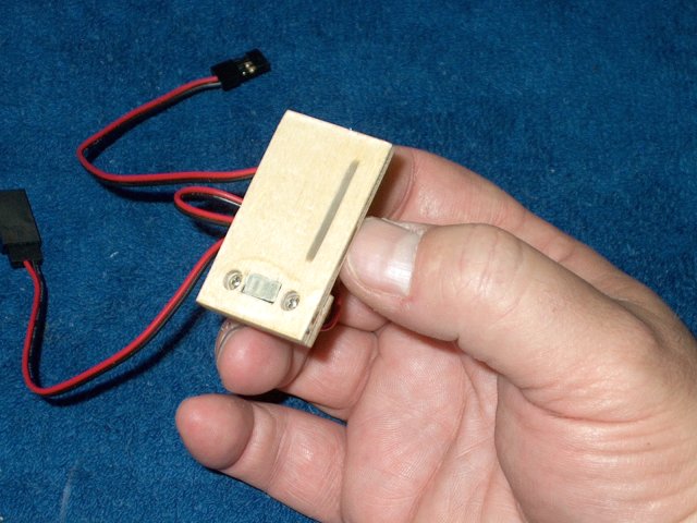
position the switch and glue in place
inside the fuselage | |
Tie wrap the ESC wire as shown leaving
some slack in the wire | |
Apply your pattern tape ove rthe location
for the switch plate | |
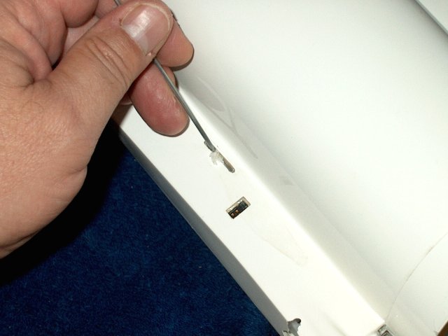
Slowly cut the slot from the outside of
the fuselage and cut the charge jack from the pattern
| |
Use a file to smooth out the slot
| |
Plug the battery into the switch and cover
with heat shrink so it will not unplug
| |
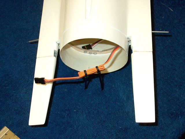
Make sure all four servo wires will reach
to the right side of the fuselage | |
Install a piece of servo tape to the
bottom of your receiver | |
Plug the servo and switch wires into the
receiver | |
Remove the cover from the servo
tape | |
Install the receiver in place as shown.
Neatly dress the wires so they are out of the way
| |
Apply masking around the edges of the
fuselage to catch any excess eopxy spillover when gluing the
vertical stab in place | |
Make a jig to hold the fuselage so
alignment of the vertical stab could be checked. Dry fith the
stab; the one in the picture was a perfect fit when held flat
against the top of the fuselage slot
| |
Apply epoxy to the bottom of the vertical
stab | |
Install the stab on the fuselage
| |
Check alignment and adjust if
necessary | |
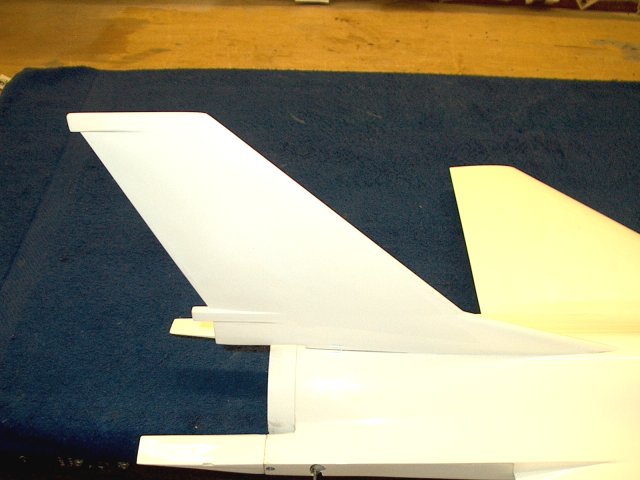
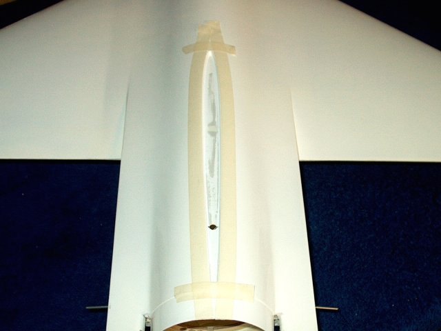
Vertical Stab installtion completed
| |
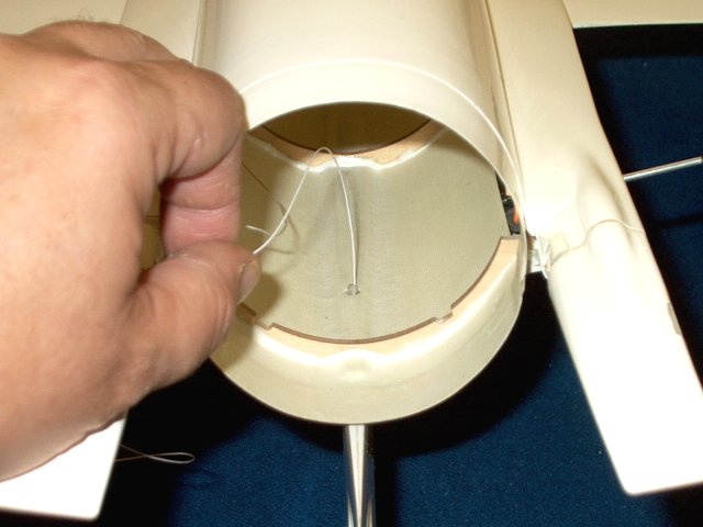
Run the antenna wire through the stab tube
as shown | |
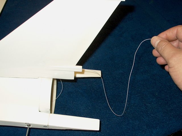
Pull the antenna wire from the rear. LEave
just a little slack inside and tape the wire with masking to
the fuselage wall | |
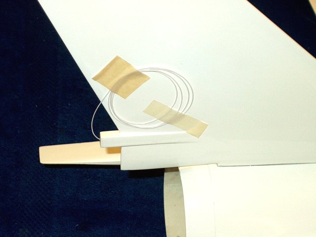
Roll up the wire and tape it to the side
of the fuselage to keep it out of the way
| |
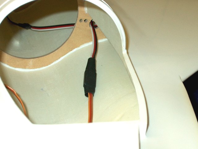
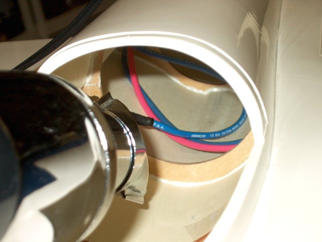
Pass the three ESC wires through the holes
in the rear | |
Run the wires though the hole in the side
of the fuselage and forward to the ESC
| |
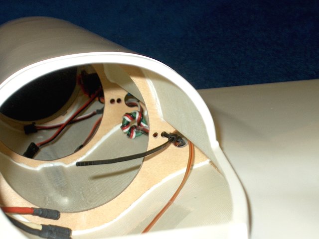
Install a piece of heatshrink over each
wire, then plug them in to the ESC. This was most easily
accomplished by inserting one had through the rear opening and
one through the front, then pluging the wires together
| |
Install the heatshrink over each
connection to keep them from pulling apart
| |
ESC Wire installation completed
| |
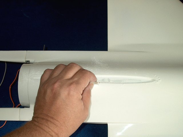
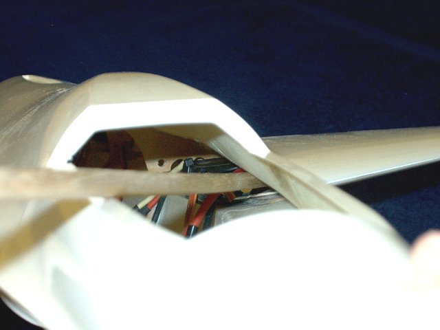
Install the intake duct in place and check
for final fit | |
Insert the all thread rod to make sure the
duct is aligned with the fuselage | |
Remove the duct, then install masking on
the inside rear | |
Tape the ESC servo wire out of the way,
then apply epoxy to top of the first former
| |
Apply epoxy to the next former as
shown | |
Install the duct in place, making sure the
hole for the allthread is aligned. Apply a thick bead of epoxy
at the joint as shown. You can push down on the duct to get
epoxy under the fuselage area at this location
| |
Clean out the wax from the slot hole in
the plywood. Check thsat you can use a rod from the slot to
turn the receiver switch off and on without binding
| |
Clean any epoxy from the lip of the duct
at the rear. A filet of epoxy can be applied at this rear
joint | |
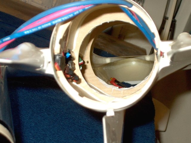
install the fan asembly in the
fuselage | |
Align the fan as shown
| |
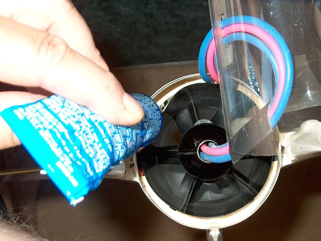
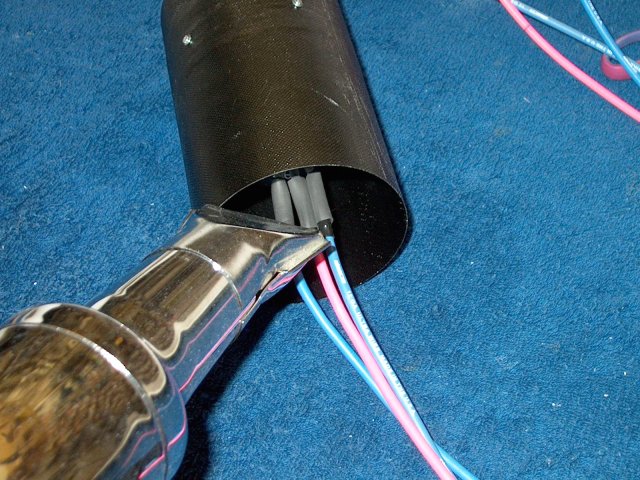
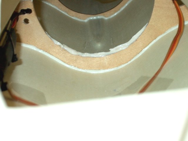
Apply silicon sealer to the rear of the
housing and rear former joint. You can flex the housing away
from the former with the dispenser tip to apply silicon to
this area | |
Clean up any excess silicon
| |
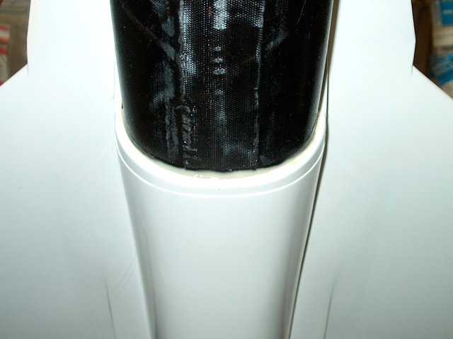
Position the exhaust tube over the rear of
the fan housing | |
Check the fit by installing the exhaust
nozzle | |
Rough up the landing areas of the intake
cover | |
Rough up the rear edge as shown and clean
up any dust | |
Rough up the fuselage area where the cover
will mount | |
Install the alltread rod and spacer
| |
Apply masking to the glue area to catch
excess resin | |
Apply masking to the cover area to catch
excess resin | |
Apply masking inside the intake to keep it
clean | |
Position the spacer slightly off to one
side so the rod doesn't go through the fuselage hole
| |
Apply epoxy to the intake as shown, as
well as the cover | |
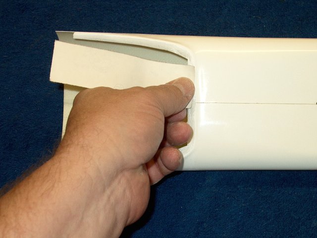
Install the cover; you will have to flex
it open to get it over the allthread rod
| |
Once the cover hole is aligned with the
intake and fuselage hole, push the rod through. Make sure the
airfoil is pointing straight. Clamp the lower joint until the
epoxy sets | |
Install the washer and nut over the
threaded rod and tighten | |
Tape the cover in position until the epoxy
sets | |
Intake Cover installation completed
| |
Apply a couple drops of CA to the threads
and nut | |
Install a Elevon so it butts against the
servo control rod. Make a mark at the front of the rod
| |
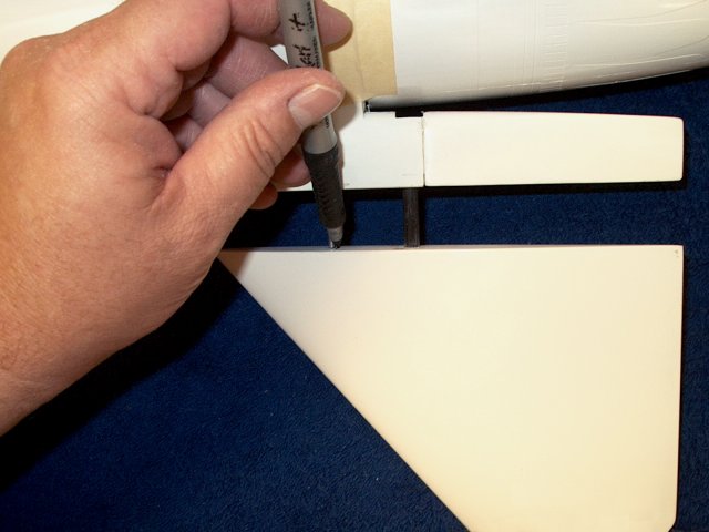
Push the servo all the way down and make
another mark at the rear of the rod
| |
Use a file to open up a slot as
shown | |
clean up the marker marks with
alcohol | |
Mark the second elevon the same as the
first | |
A piece of 1/2" x 1/16" thick Carbon Fiber
rod is used to replace the oversized and unuseable round rod
guides that were supplied in the kit. Draw a center line down
the carbon rod | |
Use a drill to make several small 5/64"
holes down the center | |
Make sure you leave at least 1/4" ov
material on each side | |
Cut, then file the slot and check the fit
over the control rod | |
The fit should be smooth without any
vertical play along the entire 1/2" long slot
| |
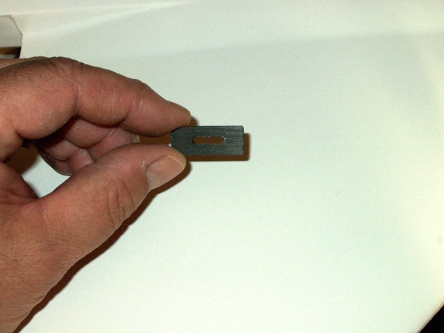
Plate contruction completed
| |
Tape the first carbon plate over the rod
and use it as a pattern for a second plate
| |
Drill several holes down the second
plate | |
Carefully cut the second slot, then file
and fit | |
Take your time and make sure it is a
smooth and slop free fit | |
Cut the second plate to length
| |
Rough up the glue side of each plate with
60 grit sandpaper | |
Drill holes and cut the slot in the second
Elevon | |
Apply servo tape to the back of the two
carbon plates. Do not apply to the glue side
| |
Remove the backing, The servo tape is used
to adhere to the T-Pin that's used to install the plates
| |
Cut the excess servo tape from each
slot | |
Apply epoxy mixed with fiberglass mil to
the slot top and bottom | |
Apply epoxy to the plate, then place a
T-Pin through the slot to the stick back servo tape
underneath | |
Install the plate in the slot usint the
homemade T-Pin, which should be wide enough to allow the layer
of epoxy to remain on the plate. Turn the face downward and
use the "T" part of the pin to pull the plate to the
wall | |
Remove the T-Pin and clean up the excess
epoxy | |
Check and align the plate with the Elevon.
Make sure it is even using the seam of the elevon for
alignment. A piece of 4-40 rod makes a good checking
tool | |
First plate is shown glued in place
| |
Apply epoxy mix to the second plate and
elevon opening | |
Glue the plate in place the same as the
first and use the rod for alignment to the seams on the
elevon | |
Remove any excess epoxy
| |
Install the washer over each Elevon
| |
Install each Elevon on the fuselage as
shown | |
Install the wheel collars and tighten them
down with the set screw pointing straight down
| |
Elevon Installation is completed
| |
Slightly sand the cockpit front and rear
if necessary | |
Sand the fuselage area for a good cockpit
fit | |
Ckeck the fit of the cockpit. Note that
there should be a lip at the top rear
| |
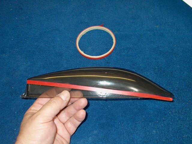
Use some trim tape along the seam of the
canopy. The seam can be diffucult to see and the tape will
help | |
Make sure you cut oversized so there is
enough material for a custom fit | |
Draw a line 1" from the front of the
Cockpit | |
Draw a line 1" from the rear of the
Cockpit | |
Use masking tape to pull the front sides
of the cockpit frame in so they fit the fuselage sides
| |
Repeat at the rear and use masking tape to
pull the rear sides of the cockpit frame in so they fit the
fuselage sides. Once adjusted, cut two 1/2" wide x 1/8" ply
strips long enough to hold the sides in place and sand them to
fit, then epoxy them in at the 1" lines you drew
earlier | |
Measure the center of the cockpit front
and mark it | |
Cockpit frame sides pulled in to the
correct shape | |
Drill a pilot hole at the cockpit front
center mark | |
Tape the cockpit in place, centered on the
fuselage. Drill a 1/8" hole by hand through the cockpit and
fuselage | |
Round the end of a piece of 1/8" diameter
wooden dowel. Cut to a length of 3/4"
| |
Push the dowel through the hole in the
front of the cockpit and glue the rear with epoxy
| |
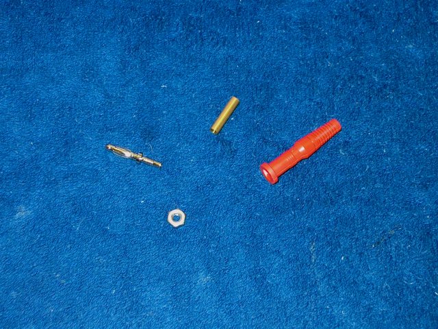
A Test Lead plug is used for the rear
retension of the canopy. An 8-32 nut fits the threads on the
read of the lead plug | |
Glue a 1/16" support plate in the rear of
the cockpit as shown | |
Drill a hole through the center so the
threads of the plug can pass | |
Install the plug through the hole and use
a nut to retain it on top. The nut can be covered with a piece
of balsa, painted as part of the cockpit
| |
Make a plate from 1/8" ply and the rear
piece from 3/8" x 3/8" hardwood, with an angled front end made
from 3/16" balsa. The hardwood block will need to be shortened
in height to fit | |
Drill a hole through the center of the
plate, leaving a small gap between the hole and the rear
hardwood support to compensate for the fuselage wall
thickness | |
Apply epoxy to the hardwood
retainer | |
Install the plate in place as shown, using
the Cockpit to insure sis-to-side alignment. Check the fit of
the Cockpit pin in the rear, then glue the tube in place when
satisfied with the fit | |
Cut the canopy so the front fits the
cockpit frame | |
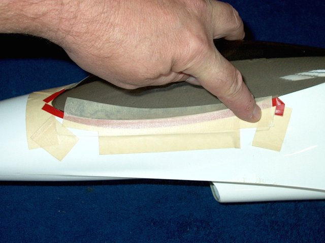
Use tape to mark the location of the rear
lip through the window, then cut away the excess
material | |
Check the fit of the Cockpit and fine sand
as necessary | |
Tape the Cockpit in place to the
fuselage | |
Apply masking tape to the Canopy as
shown | |
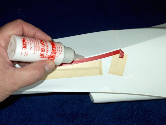
Use Canopy Glue such as RC56 to glue the
Canopy to the Cockpit | |
Install the Canopy and used the tape to
hold the Canopy to the frame until the glue dries
| |
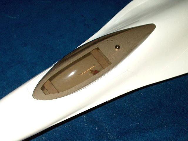
Canopy and Cockpit installation
completed | |
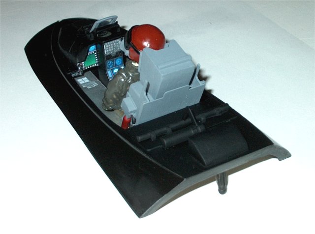
Paint you model, then a detailed Cockpit
can be made to add some realism | |
Drill a hole at the center on each side of
the Exhaust cone | |
Install #2 cap screws to retain the
exhaust | |
Set the Elevator Up throw to a minimum of
16mm; note that more is better with this model and the setting
shown was set to 18mm | |
Set the Elevator Down throw to 14mm
| |
Set Aileron Up and Down throw to
16mm | |
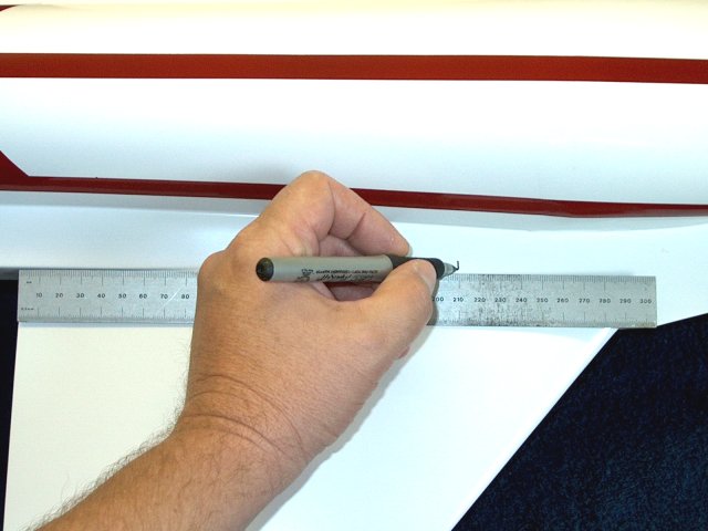
CG is measured from the rear of the wing
trailing edge. Make balance marks so you can set CG to
210mm | |
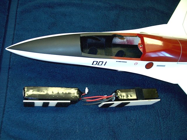
Battery trays and velcro were added to
ease battery installation and hold them in place
| |
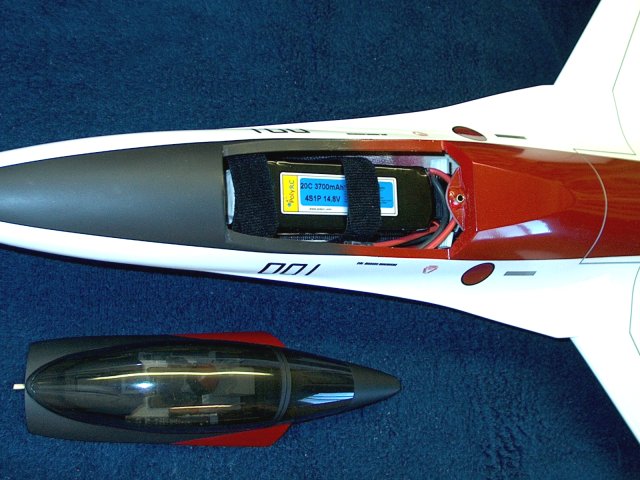
Install the batteries and check CG.
Everything should be below the canopy cover edge of the
fuselage so the canopy will sit flush
| |
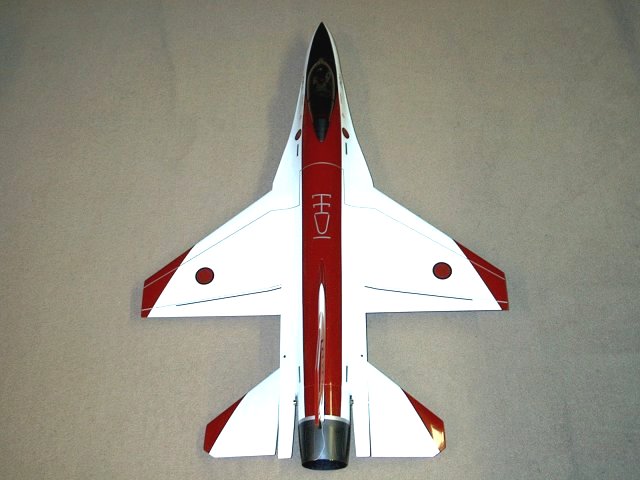
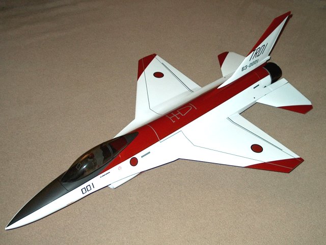
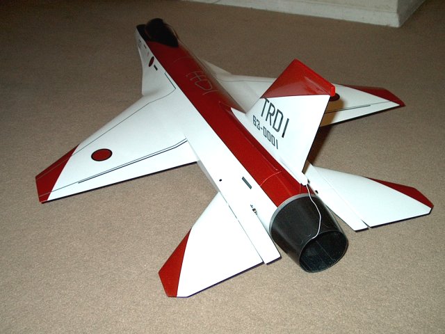
This F-16C was painted in Japan's color
scheme after their Technical Research and Development
Institute F-16 FSX/F2 scale jet aircraft
| |
Top Side view of the model
| |
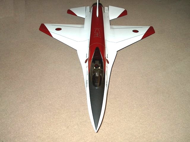
Front view of the model
| |
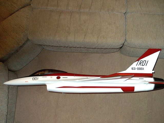
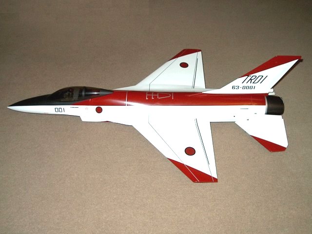
Side view showing markings on the intake
sides | |
Rear view of the F-16
| |
|