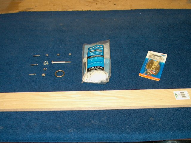
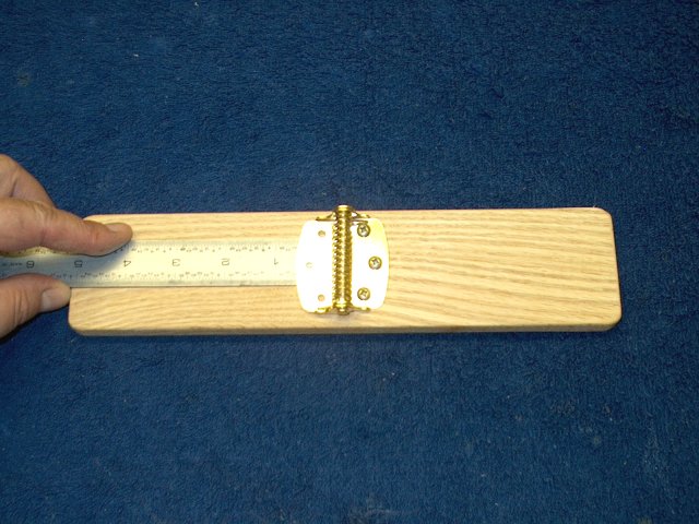
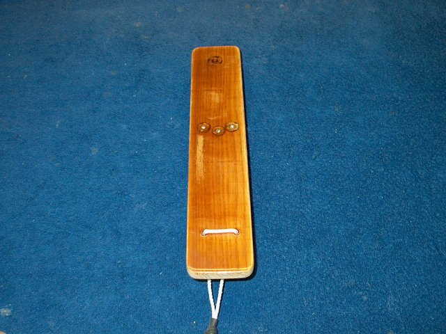
1 - A simple Bungee Pedal launcher can be
made for parts readily available at your local hardware store such
as Lowes or Home Depot. Nearly all the parts are shown
|
|
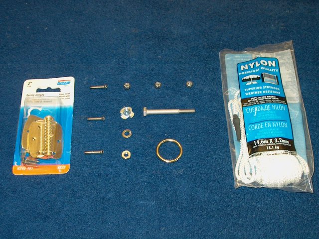
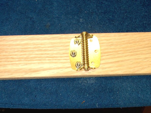
2 - Required hardware includes the Spring Hinges
as shown, Stainless Steel rustproof harware for the bolts to include
three 8-32 x 1" countersink bolts, three 8-32 nylock nuts, a 1/4" x
2 1/2" bolt, a 1/4" "T" nut, a 1/4" fender washer (not shown) and a
1/4" nut. In addition, a 1" chrome ring, a piece of 3/4" x 1 1/2"
long heat shrink (not shown) and some 3mm nylon cord round off the
necessary supplies
| |
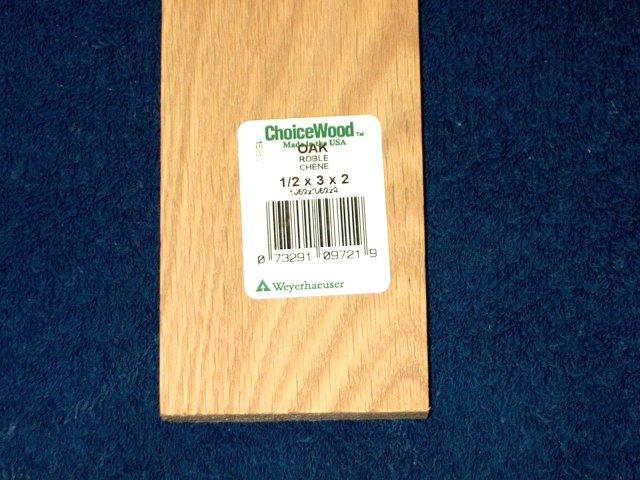
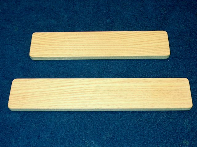
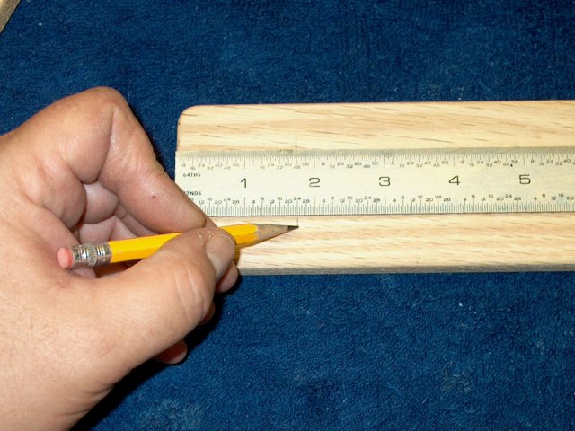
3 - The pedal is made from a single 24" long piece
of hardwood, in this case we used Oak. It is a 1/2 x 3 that is 2' long
| |
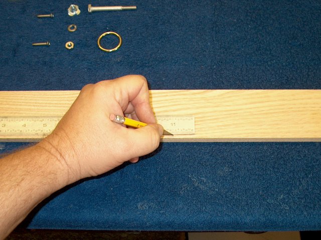
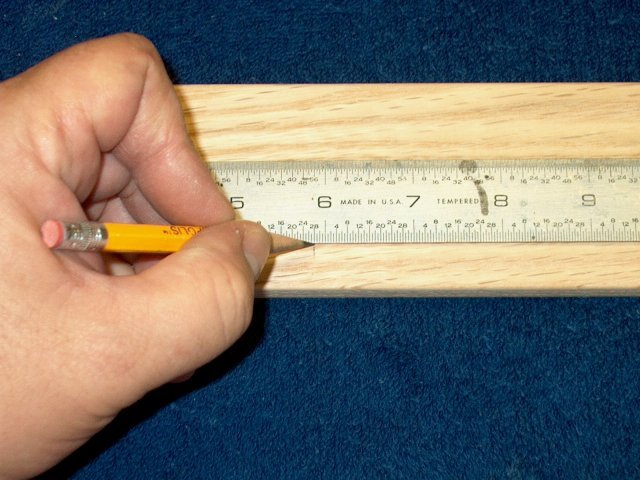
4 - Construction begins with the wood piece.
Make a mark 11" from one end of the oak board
CG. | |
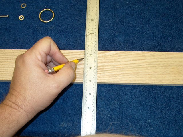
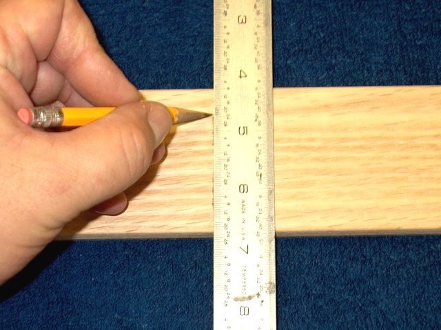
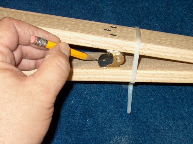
5 - Draw a vertical line at the 11" mark
| |
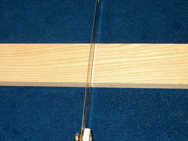
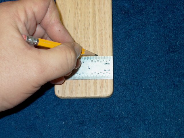
6 - Use a saw to cut the board into two pieces.
One will be 11" long and one will be around 13" long
| |
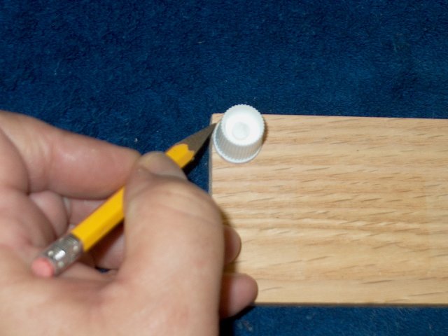
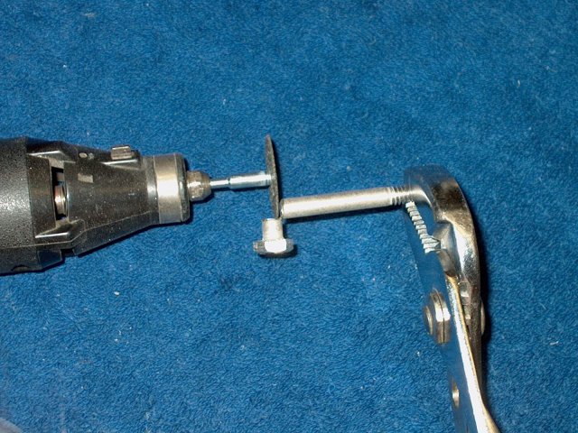
7 - Use a small 1/2" diameter cap or coin to
draw a 1/4 round at the corners of each board
| |
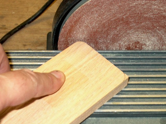
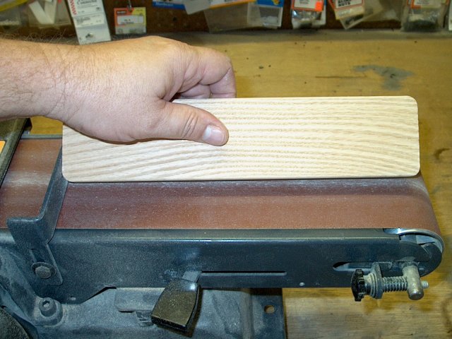
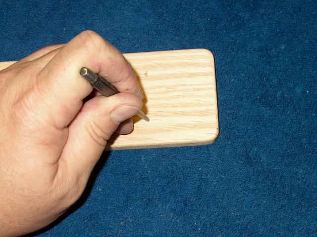
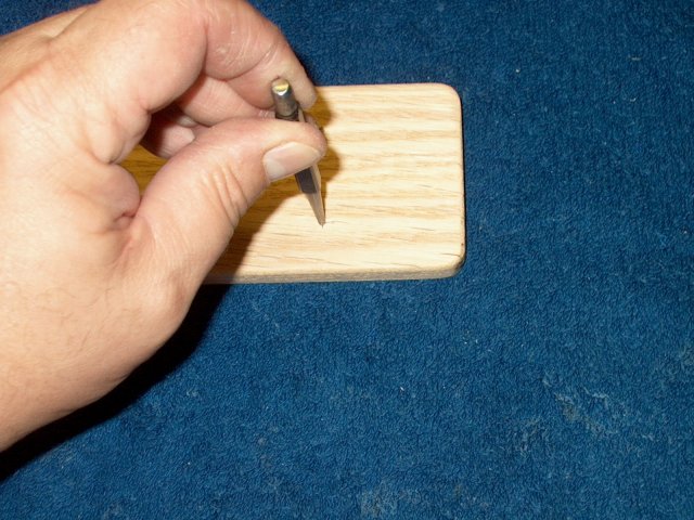
8 - Use a sander or block to round the corners as shown
| |
9 - Slightly round the edges on each board to prevent
splintering
| |
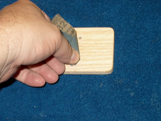
10 - Fine sand both boards, top, bottom ends and
sides
| |
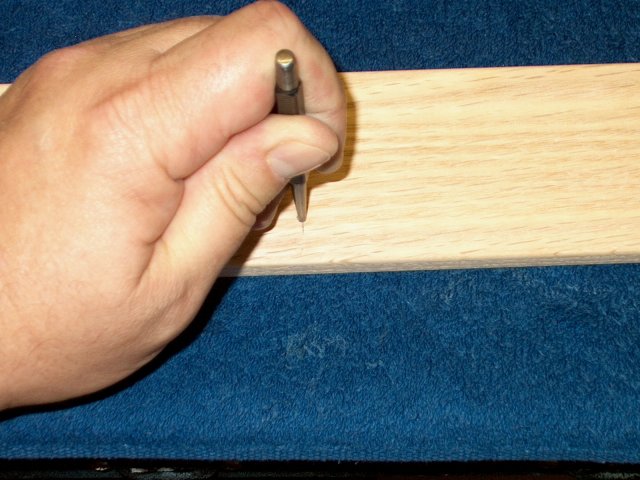
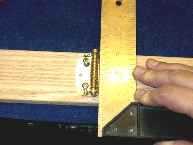
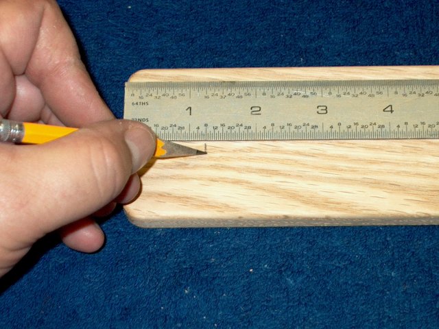
11 - Make a mark on the long board at 5 7/8" from
one end
| |
12 - Draw a vertical line using a ruler or square
at this mark
| |
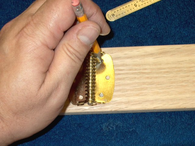
13 - Center the hinge's two inside holes over the
mark with the hinge positioned as shown, mounting side of the hinge
to the right and the 5 7/8" side of the board to the left. Draw
circles in the hinge holes to transfer their location to the wood.
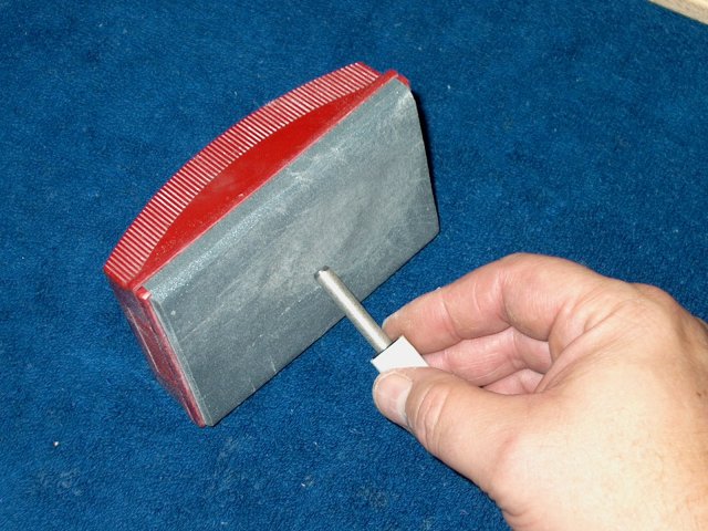
IMPORTANT: Make sure the spring is positioned perpendicular at the
location
| |
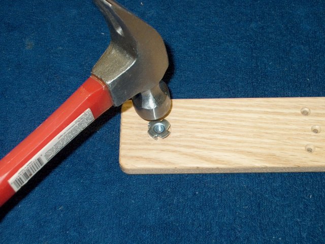
14 - Use a punch to mark the hole locations
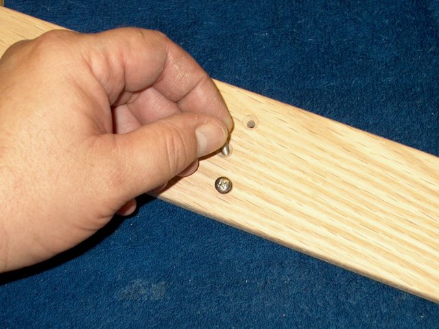
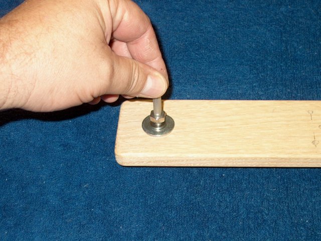
| |
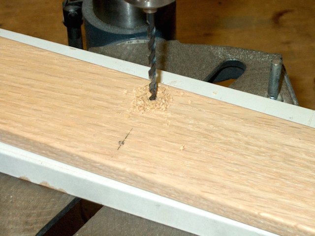
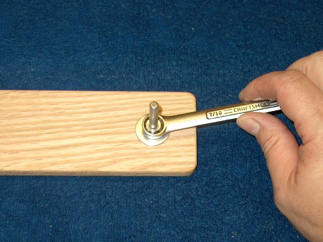
15 - Drill only the two end holes with a 5/32"
drill. A drill press is recommended to keep the holes straight and
centered
| |
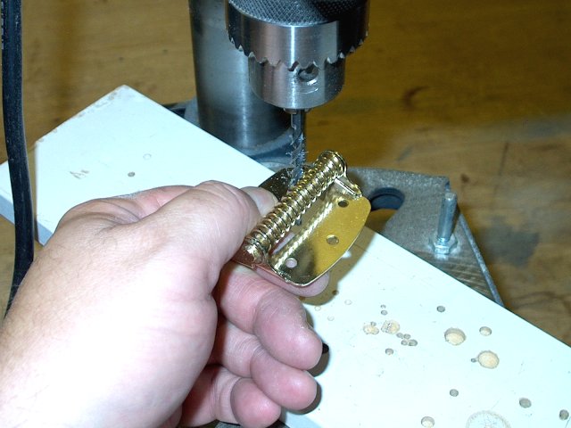
16 - You need to open up the holes a bit for
the 8-32 bolts, using the drill as shown
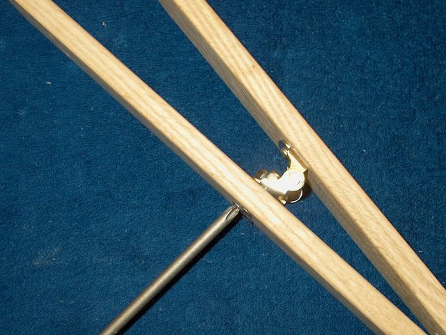
| |
17 - Install the two end bolts
| |
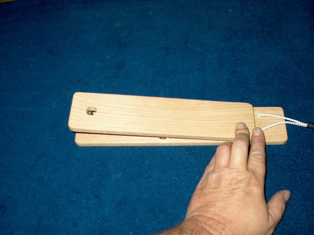
18 - Check once again that the spring is
vertical. If not, you can slightly elongate one of the holes
to straighten the hinge
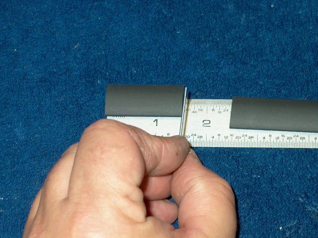
| |
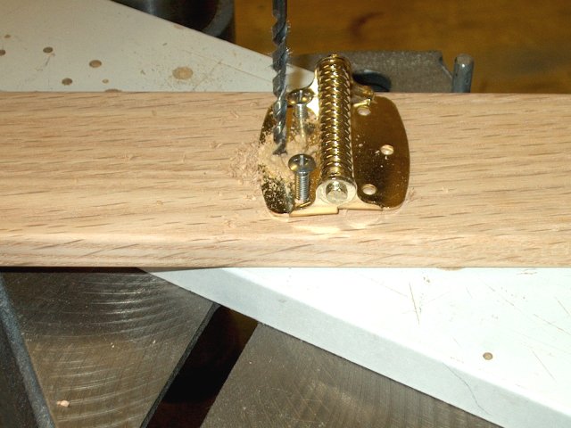
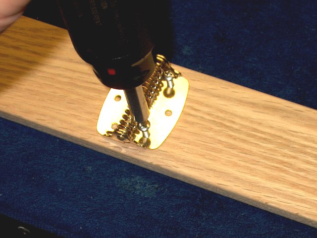
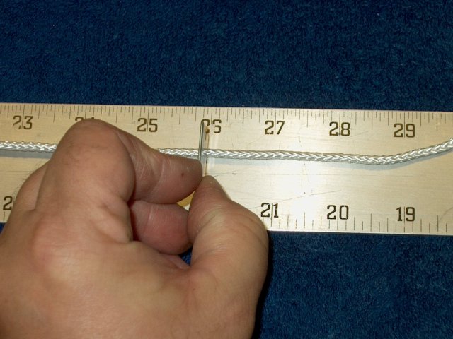
19 - Keep the hinge straight and drill the center hole
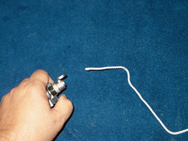
| |
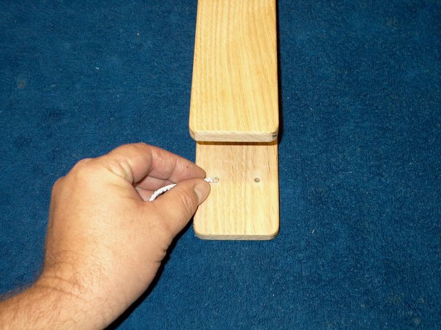
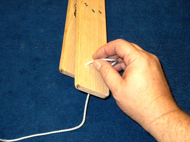
20 - The holes can be countersunk on
the bottom for the bolts
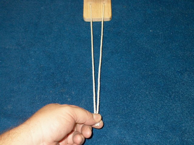
| |
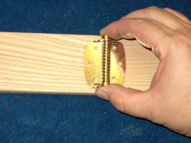
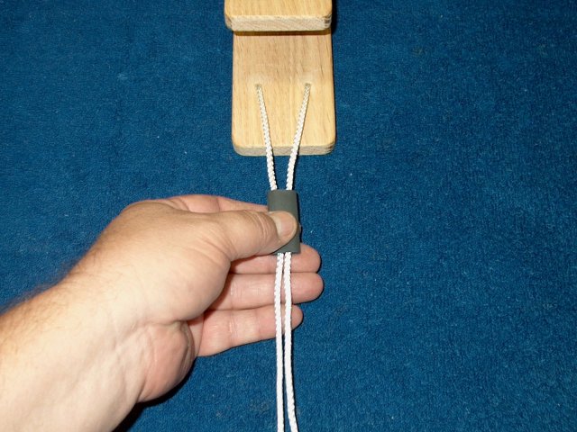
21 - Install the bolts in each hole
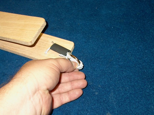
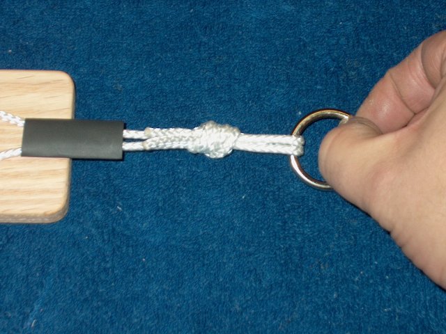
| |
22 - Use nuts to hold the hinge in place and centered
| |
23 - Place the short piece over the long board, with
the end flush as shown on the measured side (the 5 7/8" marked side)
| |
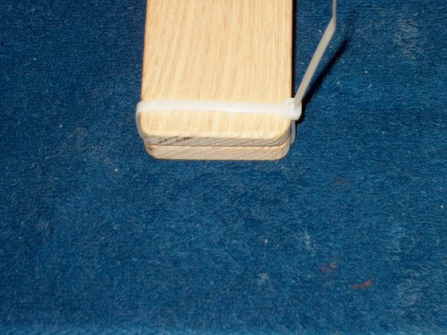
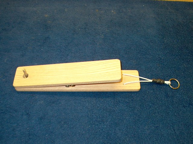
24 - Use a tie wrap to temporarily secure the
end of the boards
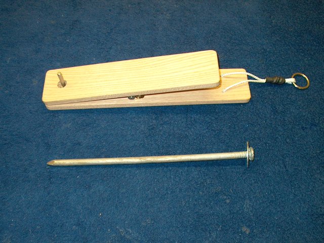
| |
25 - Flip an hold the hinge up, then set the
short board over it and while holding it together, use another
tie wrap to keep it in place. Align the end of the two boards
flush and keep the sides of each board even with eachother, then
transfer the hinge location to the short board, outlining it with
a pencil
| |
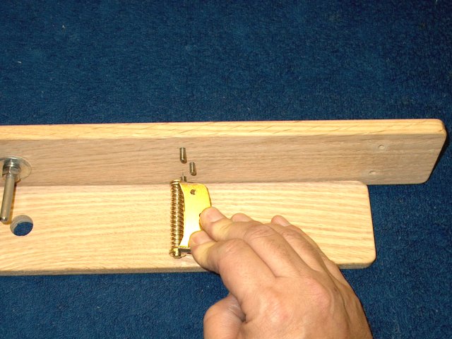
 Remove the short board by cutting the tie
wraps and be careful of the rebounding spring hinge. Remove the
hinge from the long board and place the correct short board side
over the drawing Remove the short board by cutting the tie
wraps and be careful of the rebounding spring hinge. Remove the
hinge from the long board and place the correct short board side
over the drawing
| |
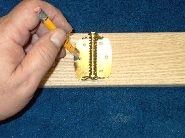
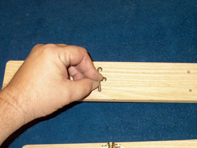
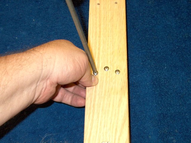
27 - Make a mark at each hole location
| |
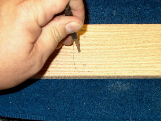
28 - Mark each location center with a punch
| |
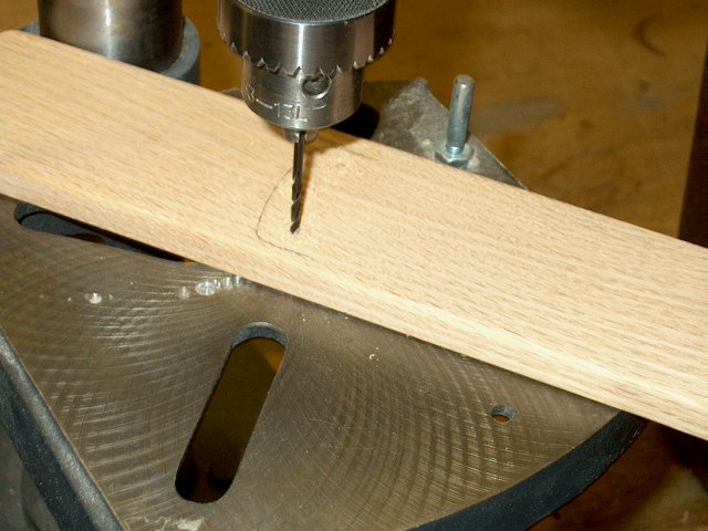
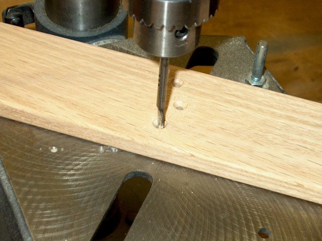
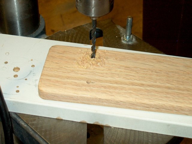
29 - A small 3/32" hole is drilled at each
screw location. The drill is set so it does not go all the way
through the wood, leaving the last 1/16" or so undrilled. This
will keep the top of the board looking clean
| |
30 - Make a mark on the end of the long board,
at the short 5 7/8" side. The mark is 1 1/4" from the end
| |
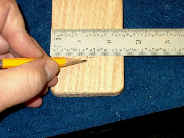
31 - Draw a center line over the mark you just made
| |
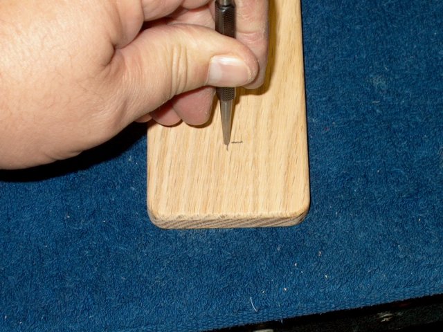
32 - Use a punch to mark the location
| |
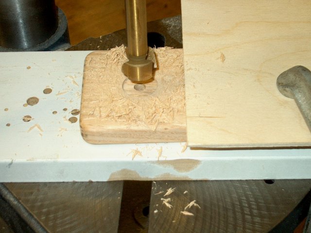
33 - Drill a 1/4" hole at the center. If you
wish to countersink the location of the "T" nut, then use a 3/4"
forstner and cut about 1/16" deep at the center bottom of the
board. Make sure you countersink the bottom side
| |
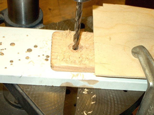
34 - Open the hole to the width of your
1/4" "T" nut, which may be around 5/16" - 3/8" depending on the
"T" nut you purchase
| |
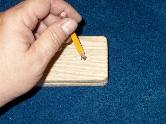
35 - Transfer the location of the 1/4" hole
from the long board to the short board. Make sure you mark the
correct end of the short board
| |
36 - Use a 5/8" Forstner to bore a hole in
the short board at the location you marked
| |
37 - On the opposite end of the long board,
make two marks at 1 3/4" from the end as shown
| |

38 - Measure in 5/8" from one side of the
board to make the cross mark
| |
39 - Make another mark 5/8" from the other
side of the long board
| |
40 - Use a punch to mark the first location for drilling
| |
41 - Use the punch to finish marking the second location
| |
42 - A 5/32" drill is used to bore a hole
through the long board at each of the locations you marked
| |
43 - Use a hobby knife and sandpaper to
slightly round the exit areas of each hole on both the top and
bottom of the board. This is so there are not any sharp edges
to cut into the nylon cord
| |
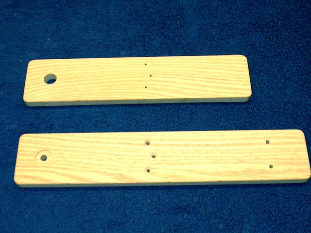
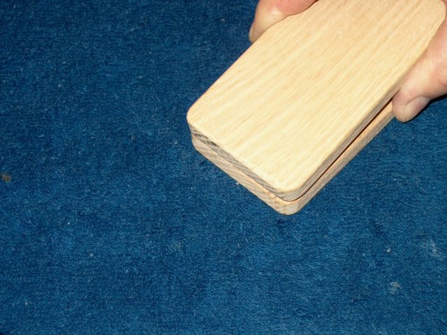
44 - Both boards have been prepared,
drilled and sanded and are ready for assembly
| |
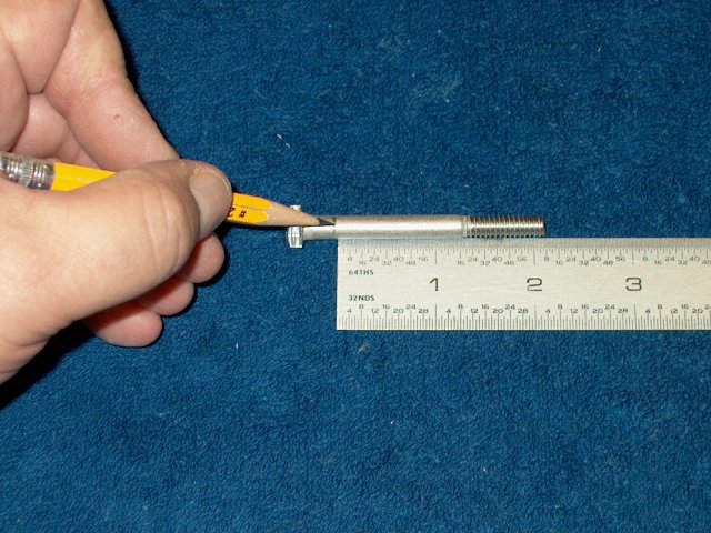
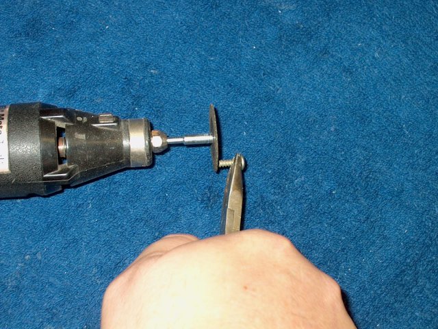
45 - Mark the 1/4" bolt 2 1/8" from the
threaded end. Note that Stainless Steel hardware was used in the
assembly to prevent rusting
| |
46 - Cut the head off the bolt at the mark as shown
| |
47 - Grind and sand the cut area to round it
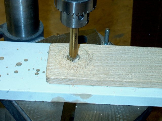
| |
48 - Hammer the "T" nut into the bottom of the
long board until it is flush
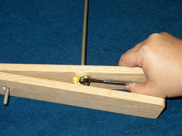
| |
49 - Install the large fender washer, then
the lock washer and nut over the bolt/pin as shown. Screw the
bolt pin into the "T" nut
| |
50 - Use a wrench to tighten the bolt pin
| |
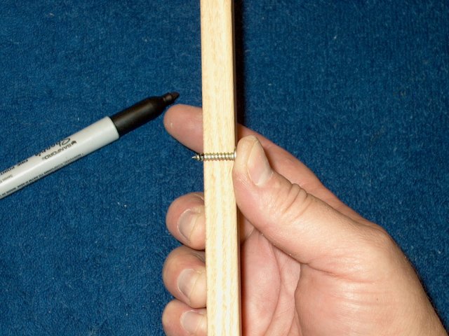
51 - Place a screw included in the pack
of hinges along the side of the short board. Mark each screw
to be cut so they will just be clear of punching through the
top of the board
| |
52 - Cut each screw to shorten them and check
the length so they are shorter than the board thickness
| |
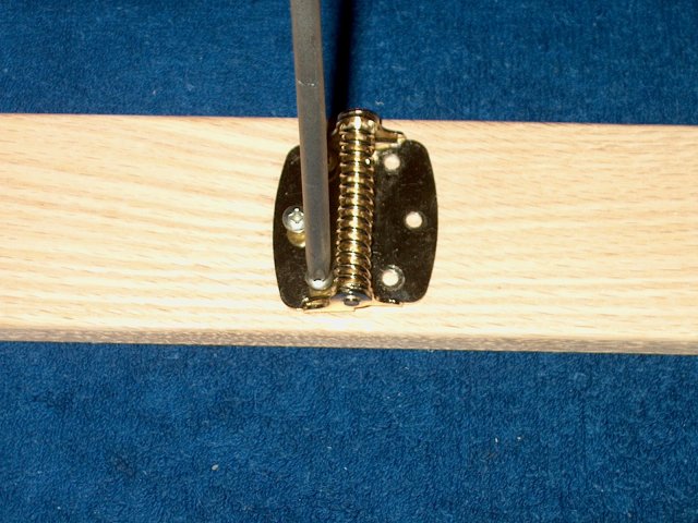
53 - Install the hinge using the screws you
just cut. Tighten them down all the way and keep the hinge spring
centered
| |
54 - Slide a ruler under the hinge to assist
with the next step to install the long board
| |
55 - Install the three 8-32 bolts through the
bottom of the long board
| |
56 - Position both boards, and while holding
the spring, install the long board so its bolts run through the hinge
| |
57 - Hold the pieces together and start the
nylock nuts as shown, holding them with one hand while turning
the screwdriver with the other hand
| |
58 - Photo shows nylock nuts in position
| |
59 - Make sure the two boards are lined
up with eachother and then tighten all three bolts
| |
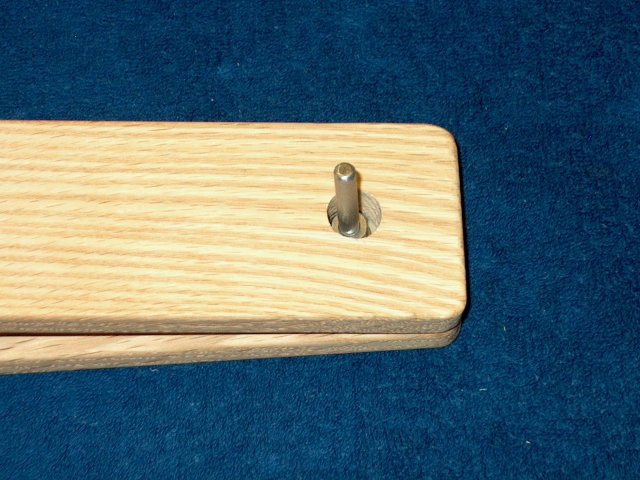
60 - With the bolts tightened and the boards
centered, the 1/4" bolt pin should be centered in the hole as shown
| |
61 - When depressed, the pedal lifts
up and the hole should clear the pin by about 1/4"
| |
62 - Cut a piece of 3/4" heatshrink to a
length of 1 1/2"
| |
63 - Cut a piece of the 3.2mm nylon cord
to a length of at least 26"
| |
64 - Use a lighter to melt and seal each
end, which will keep the cord from fraying
| |
65 - Install the cord in one of the two
rear holes from the top
| |
66 - Loop the cord from the bottom to
the second hole and thread back through
| |
67 - From the top, pull each cord and
adjust until they are the same length
| |
68 - Slide the heatshrink over both cords,
then slide the 1" chrome ring over both cords
| |
69 - Fold the cord ends over and tie them
in a knot as shown, passing the ring through the cord loops
| |
70 - Pull and tighten the knot so it is tight.
You can dab it if you wish with a bit of epoxy
| |
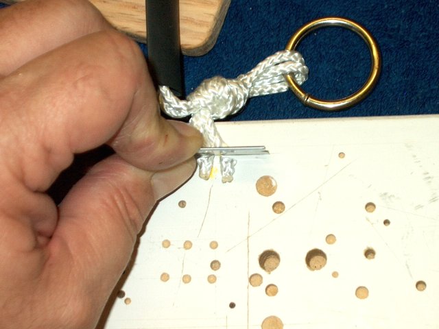
71 - Cut some of the excess off the ends,
leaving about 1/2" exposed. Re-seal them with a lighter to prevent
fraying
| |
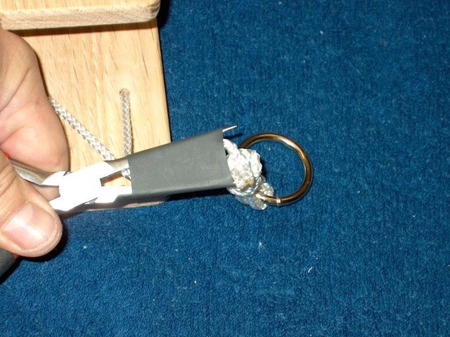
72 - Stretch and slide the heat shrink over
the knot as shown
| |
73 - Use a heat gun to seal the knot
| |
74 - You can add a thin layer of epoxy
to the bottom of the long board to waterproof it from the
ground during use
| |
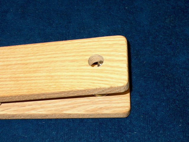
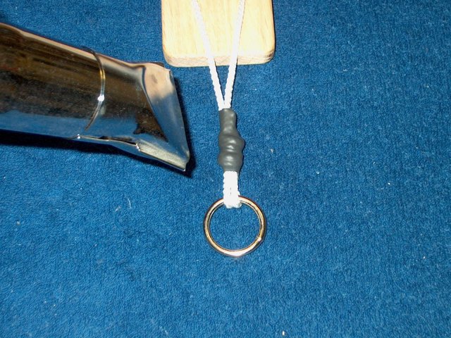
75 - The completed pedal assembly is shown.
The aircraft release loop is placed over the 1/4" pin
| |
76 - When depressed, the pedal pushes the
release loop off the pin
| |
77 - A 12" galvanized nail with a matching
fender washer can be installed through the chrome ring and is
used to stake down the rear of the pedal. This completes the
assembly of the Bungee Release Pedal
| |

This Website and all documents herin are Copyright © 2012 www.scalerocketry.com -
All rights reserved.
| |