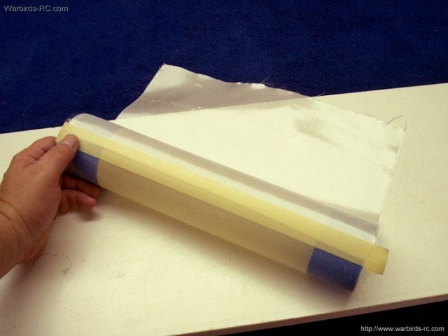
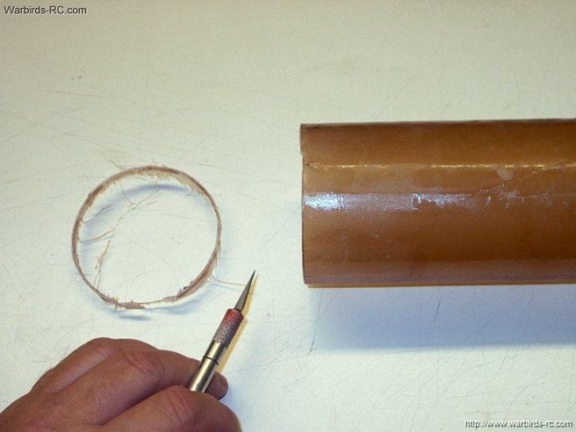
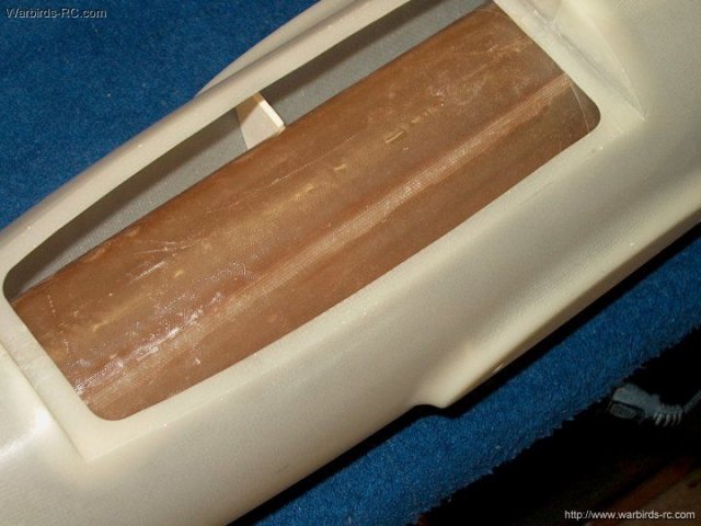
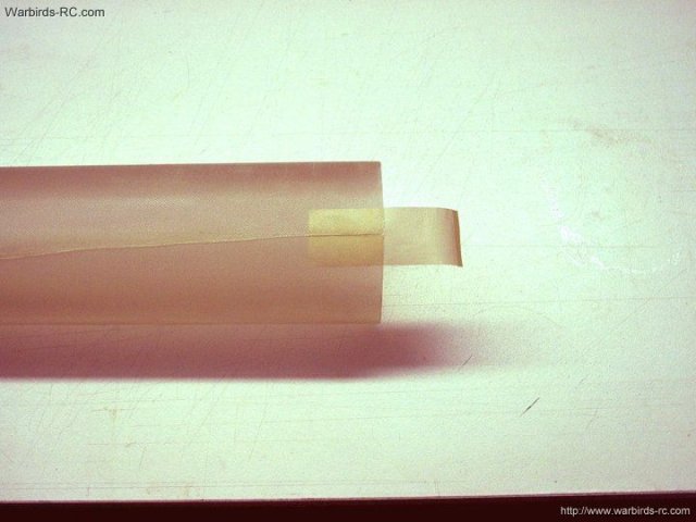
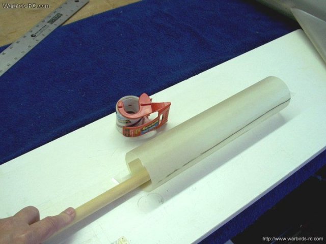
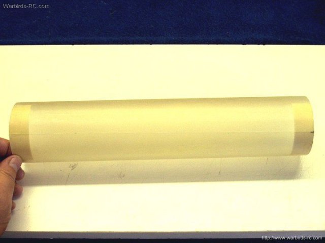
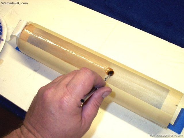
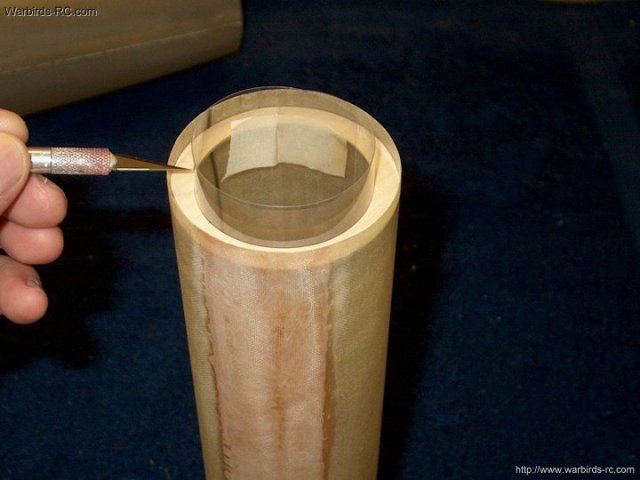
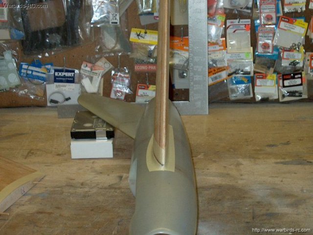
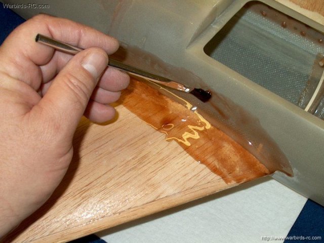
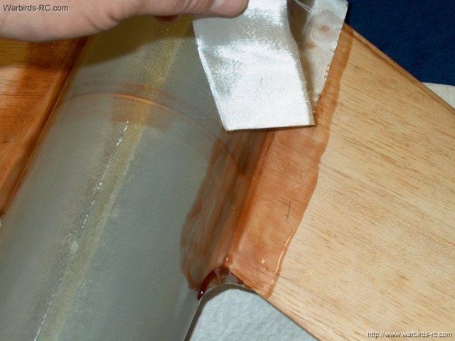
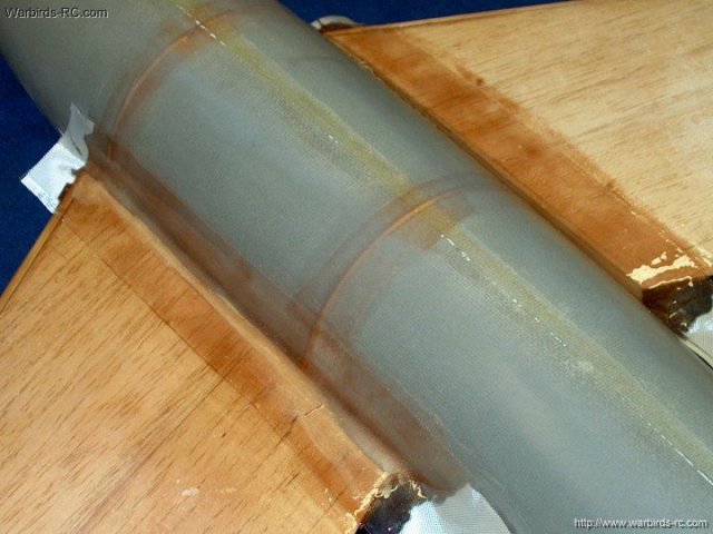
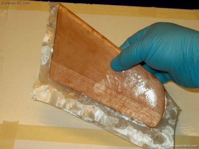
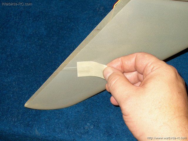
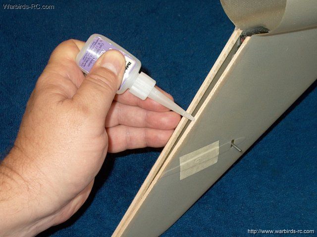
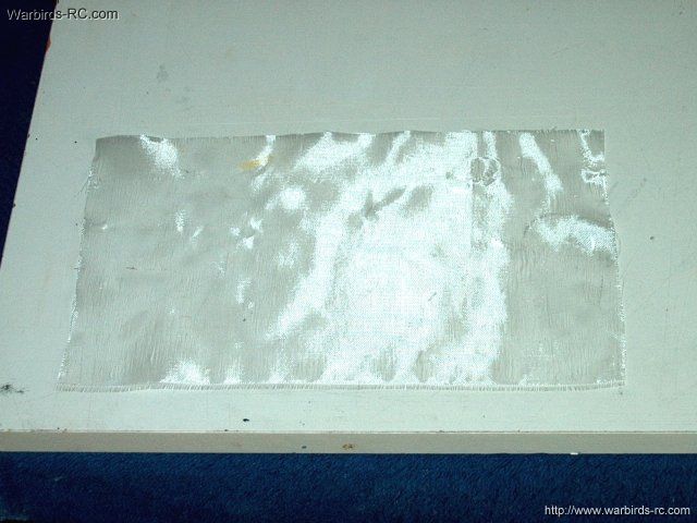
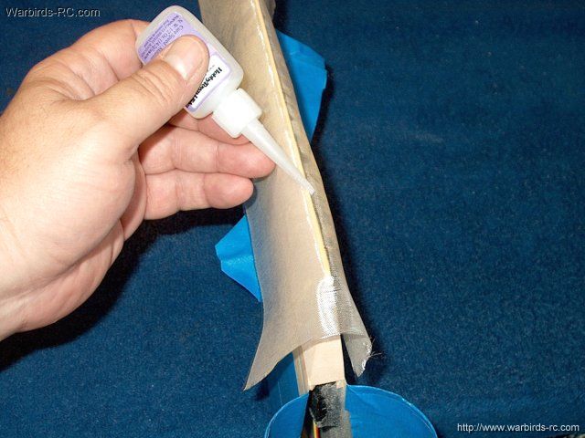
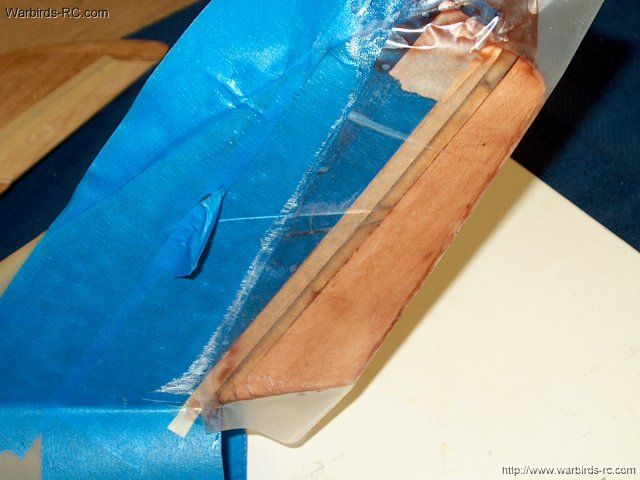
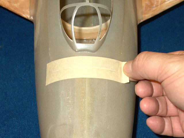
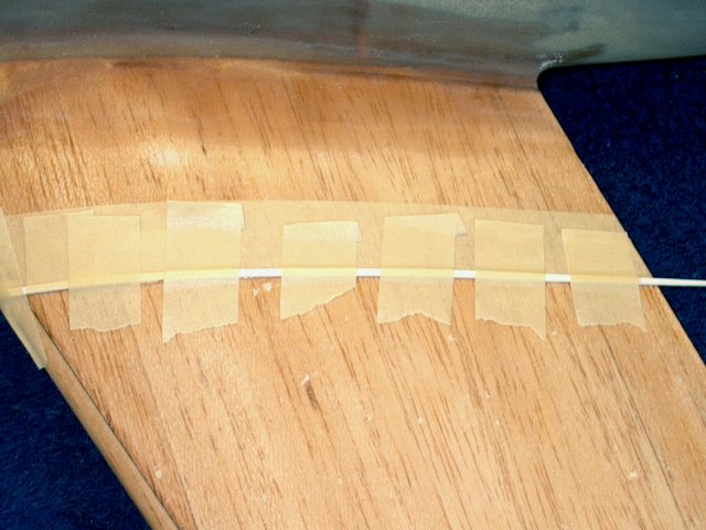
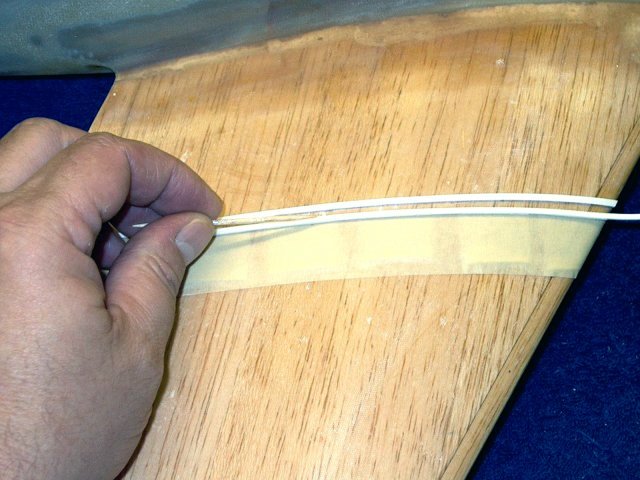
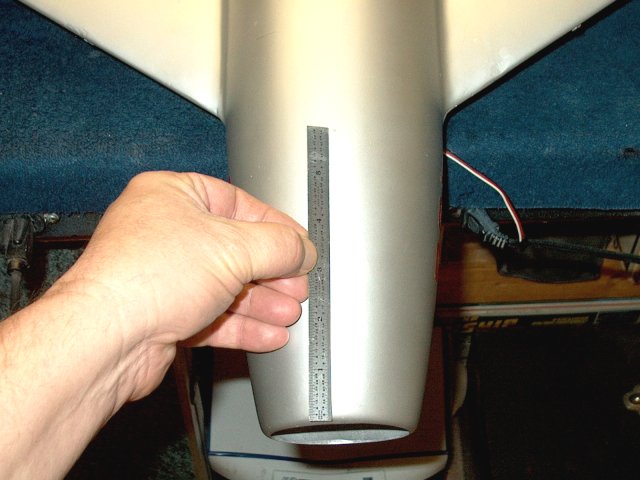
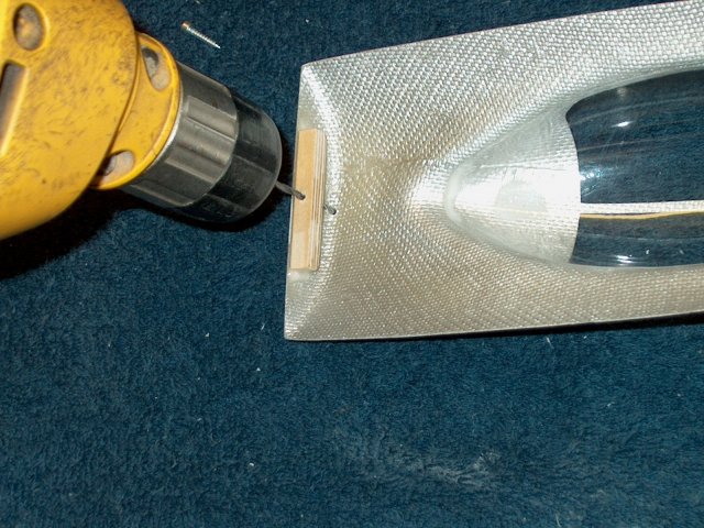
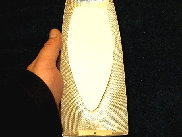
6oz glass cloth is taped to the duct as
shown | |
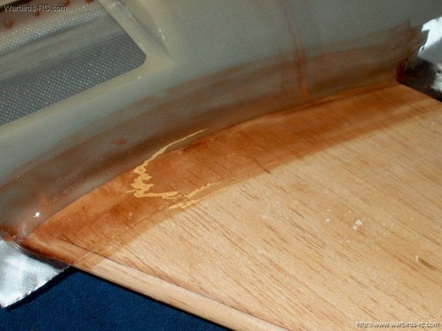
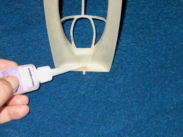
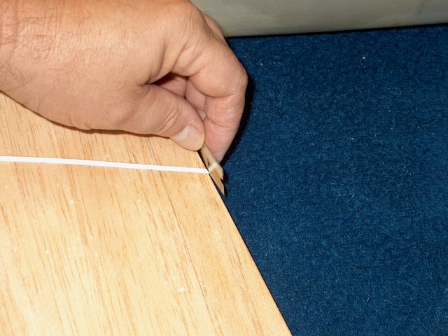
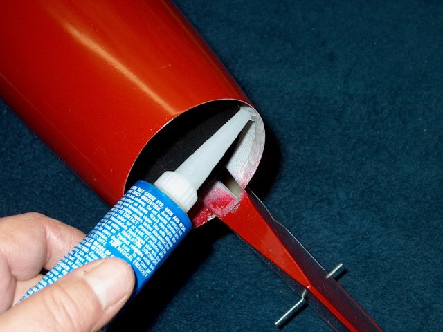
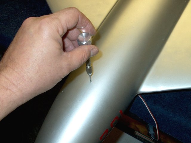
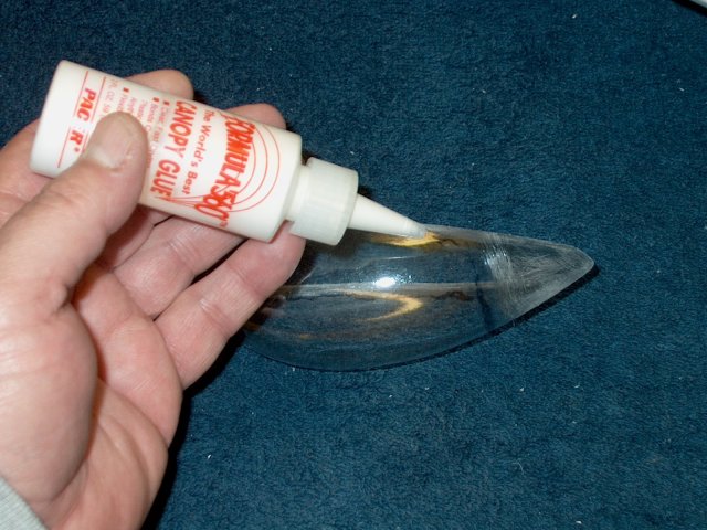
Medium CA is used down the side to anchor
the cloth for glassing | |
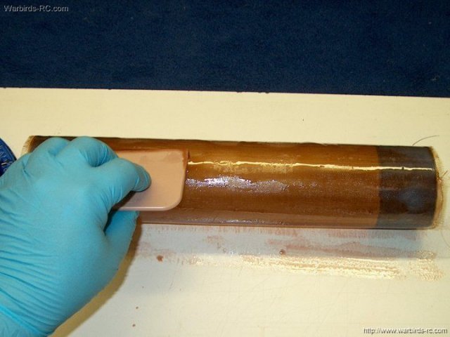
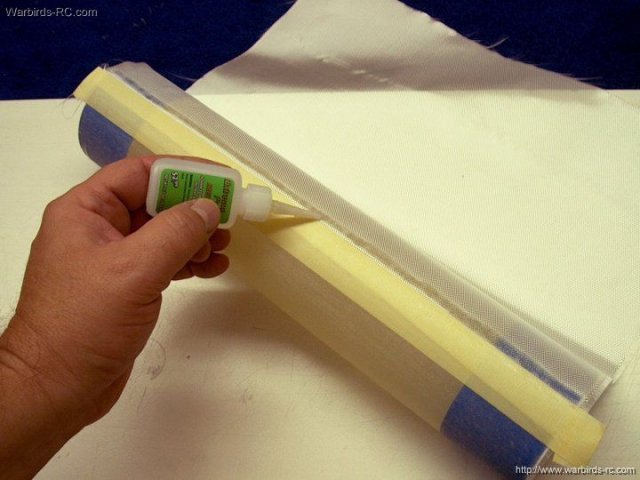
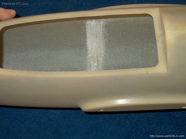
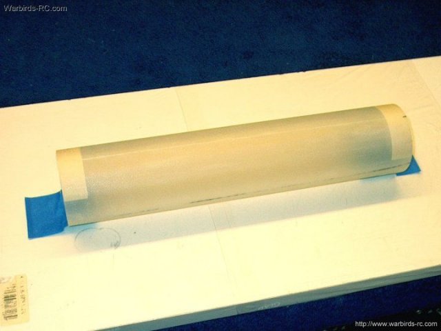
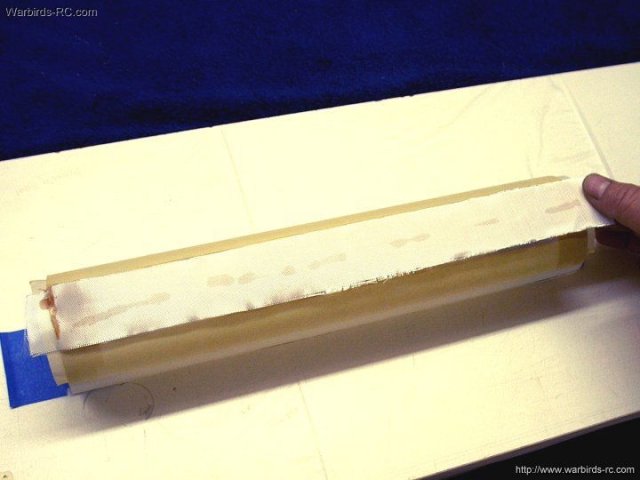
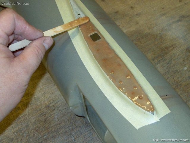
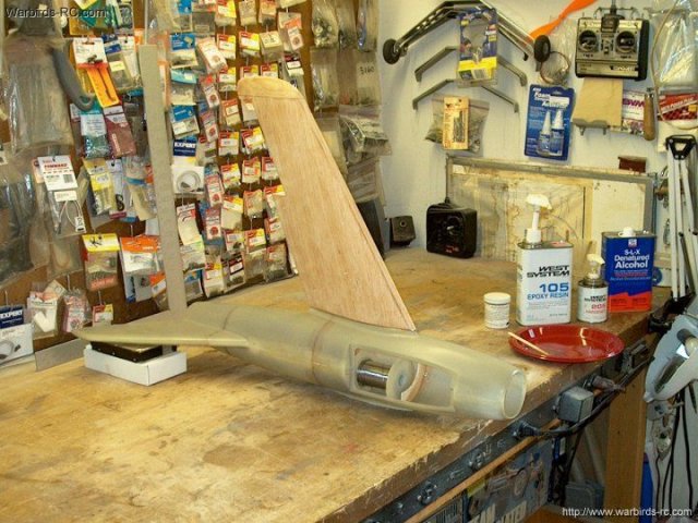
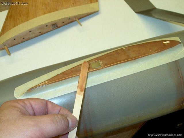
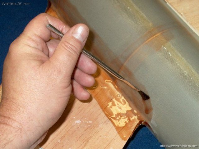
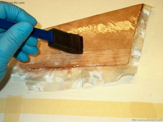
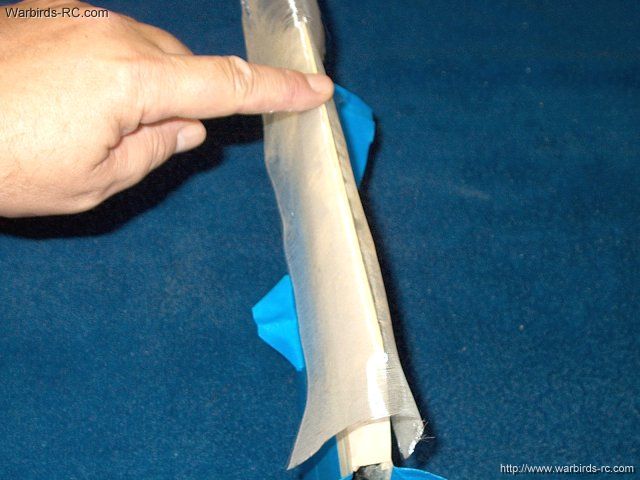
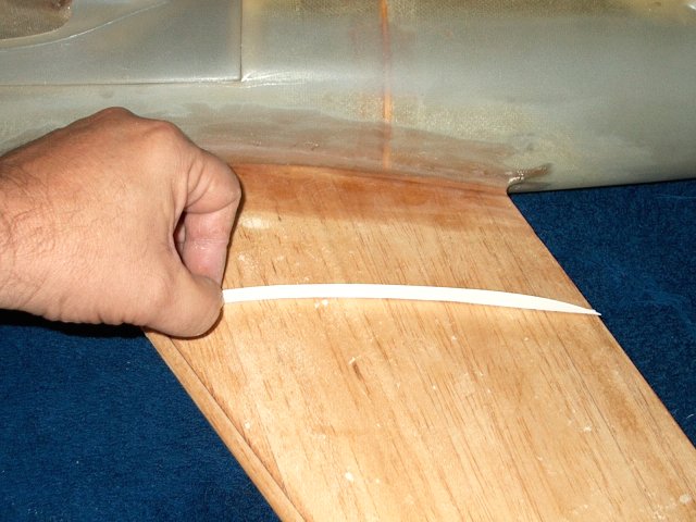
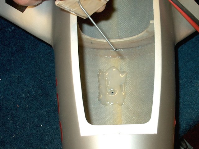
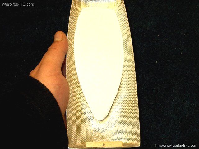
A good glassing resin such as West Systems
is used to glass the cloth to the intake
| |
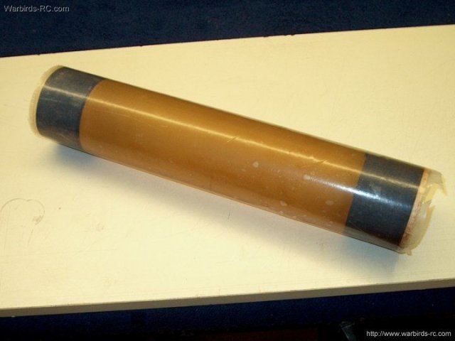
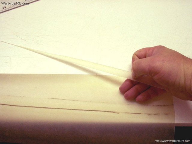
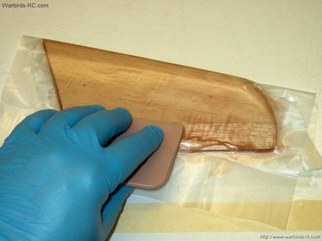
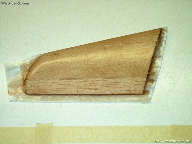
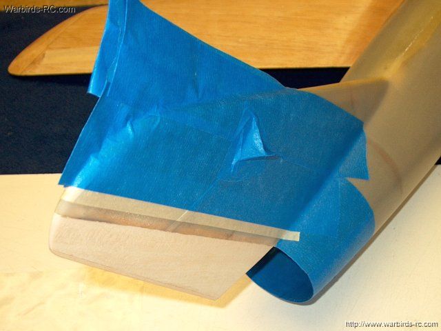
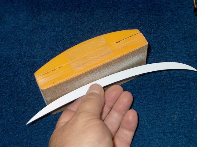
The intake is wrapped in a plastic sheet
and left to set |
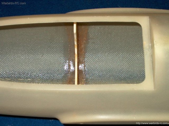
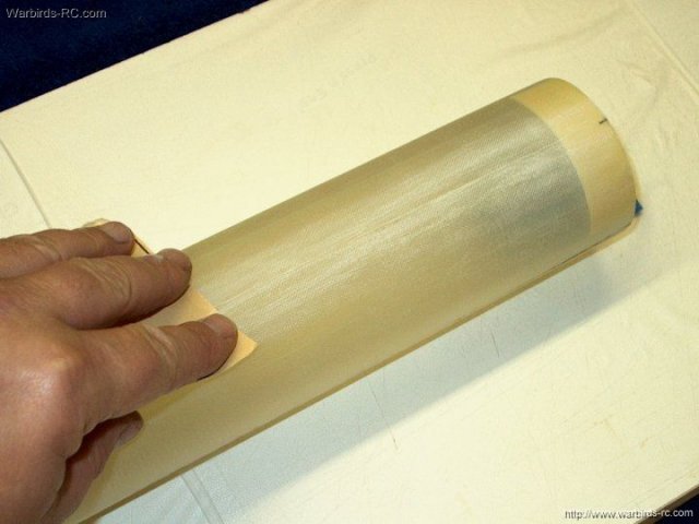
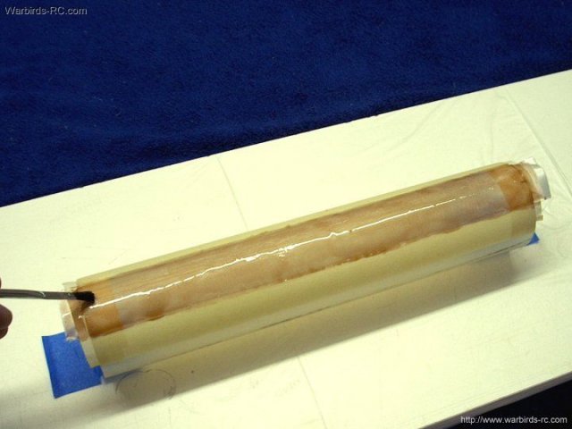
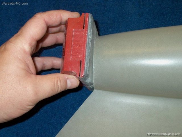
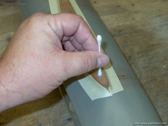
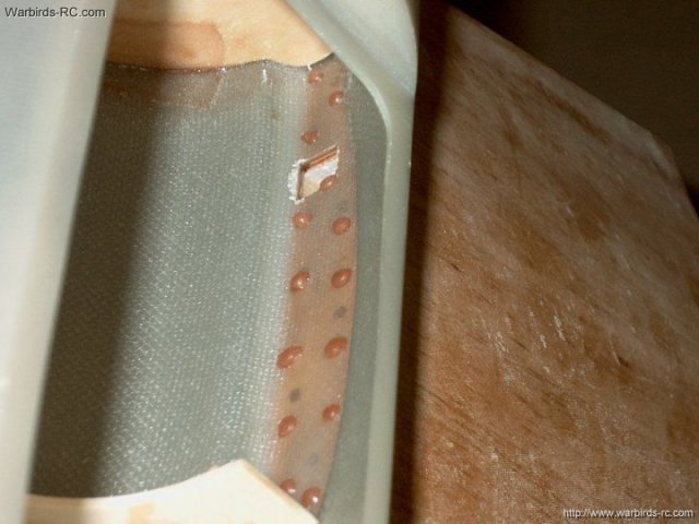
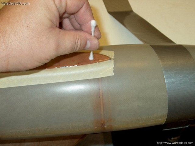
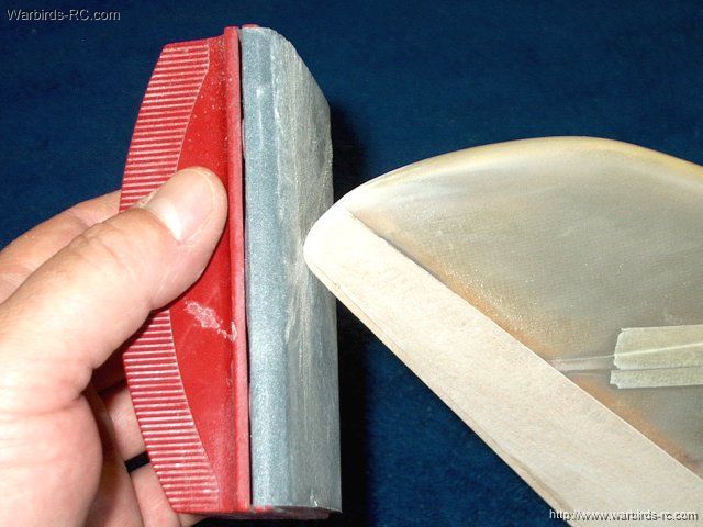
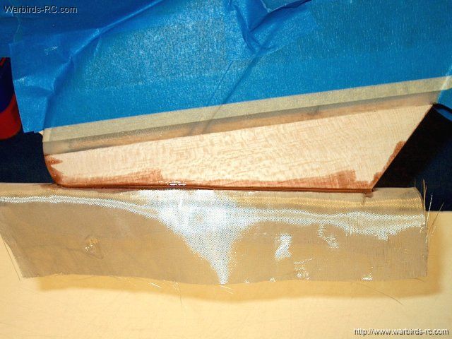
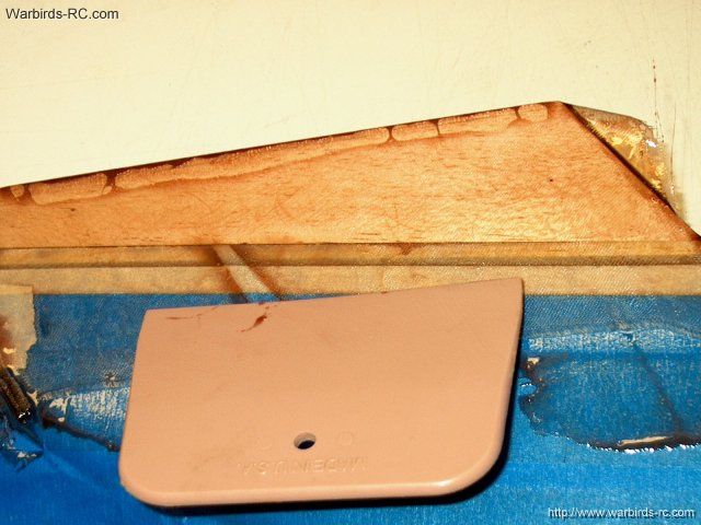
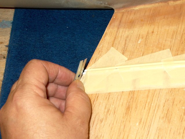
The sheet is removed, the end caps are
removed and the ends are trimmed while the epoxy has set but
is still soft. Keep an eye on the inside for epoxy dripping,
which actually seaped through pinholes in the thin intake tube
material during the glassing process. Keep it clean with
denatured alcohol and a paper towel so you don't have these
bumps and drips to deal with later | |
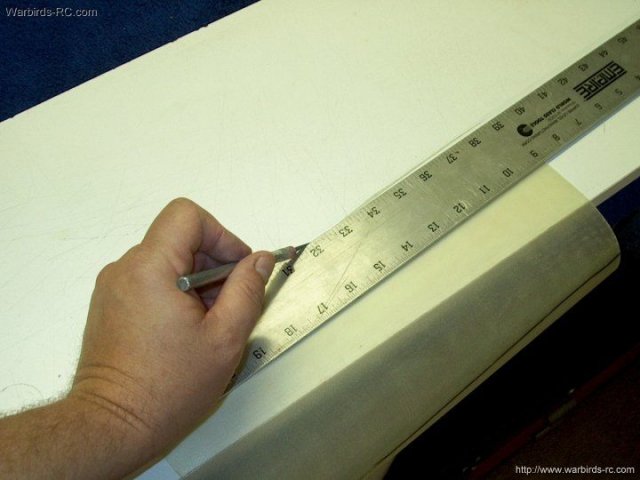
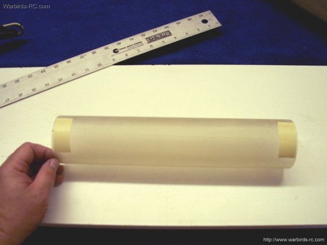
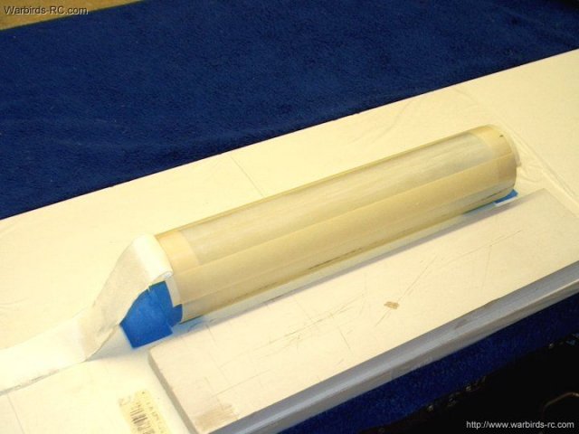
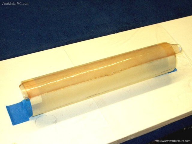
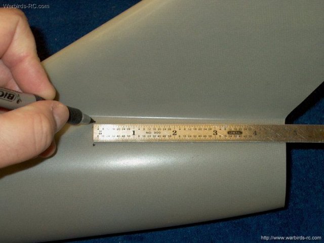
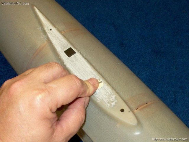
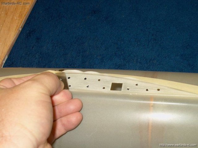
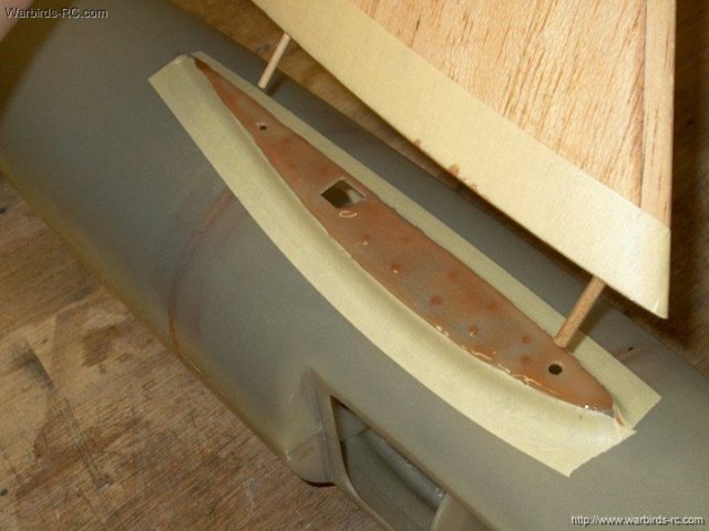
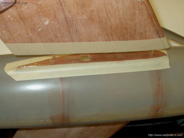
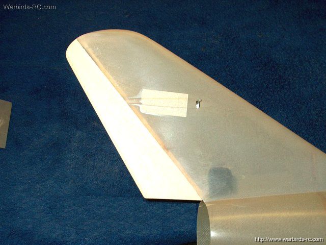
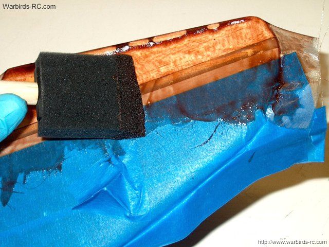
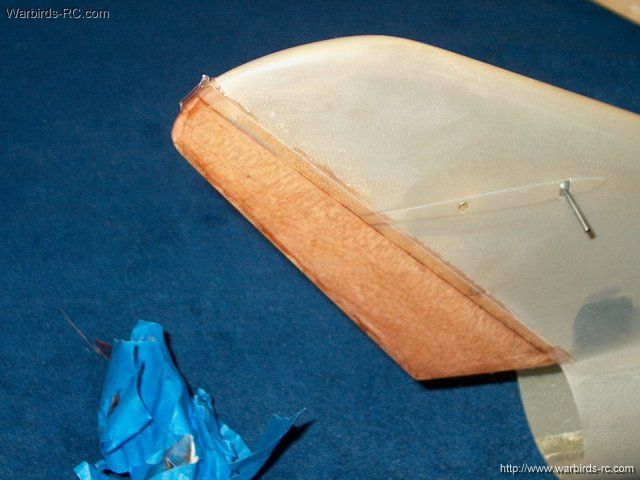
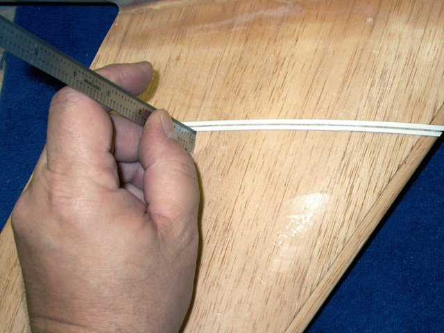
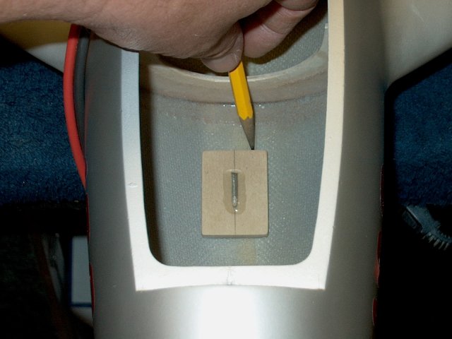
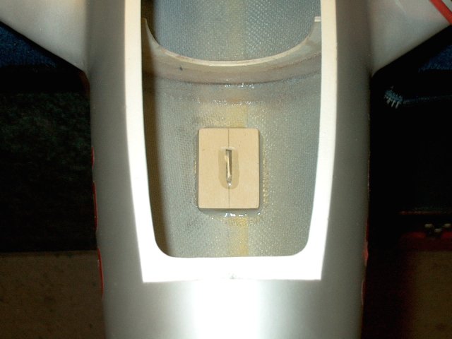
Once completely dry, remove the inside
packing tape. A piece of 1/2" wide masking is installed down
the center of the fan housing and the intake is installed
flush to one end of the tape and held temporarilly in place
with packing tape or electrical tape
| |
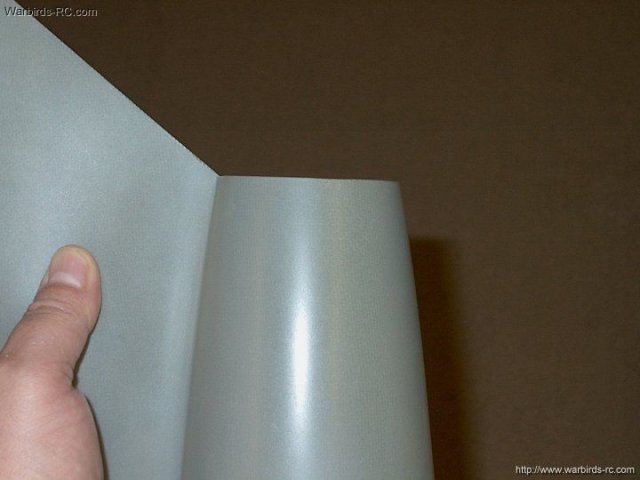
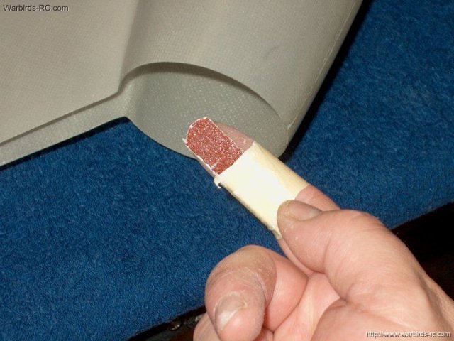
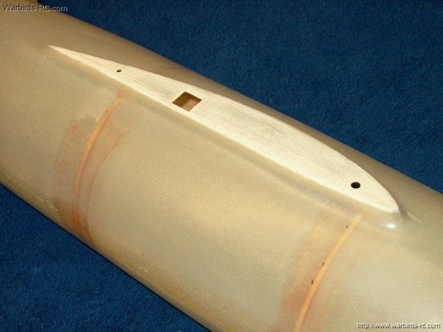
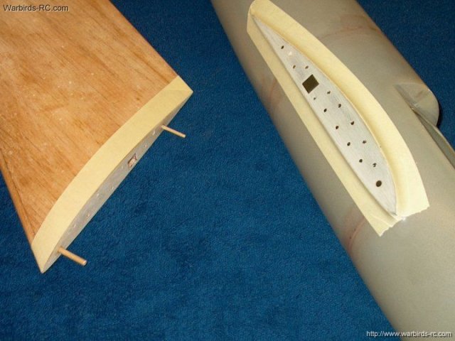
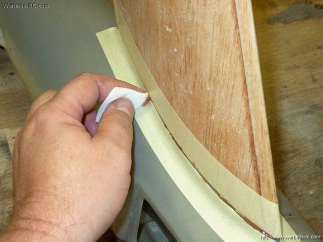
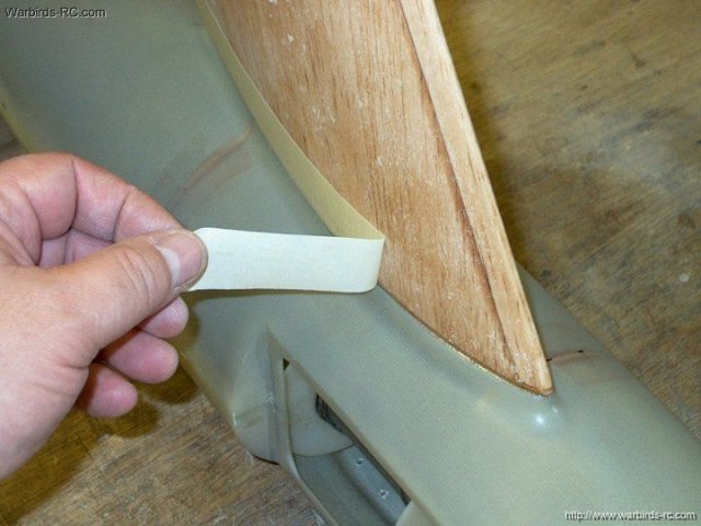
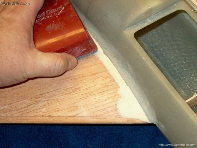
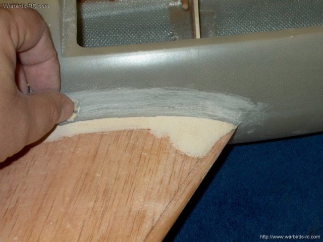
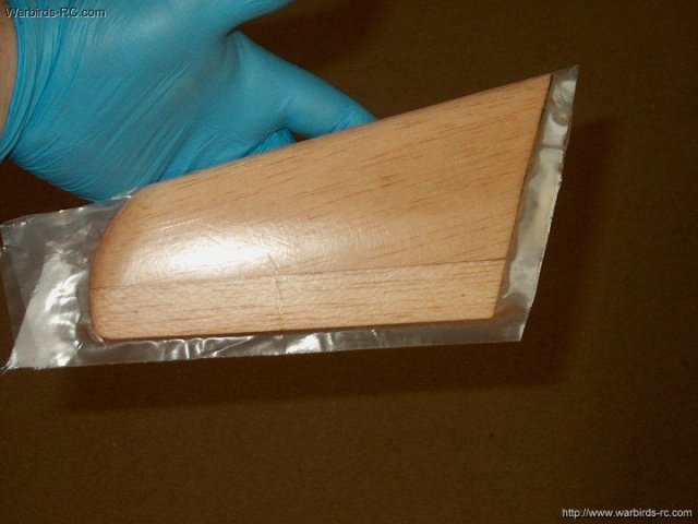
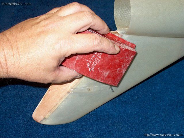
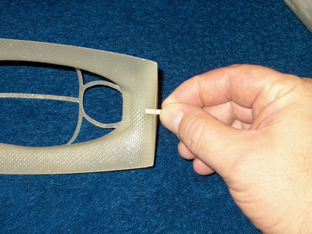
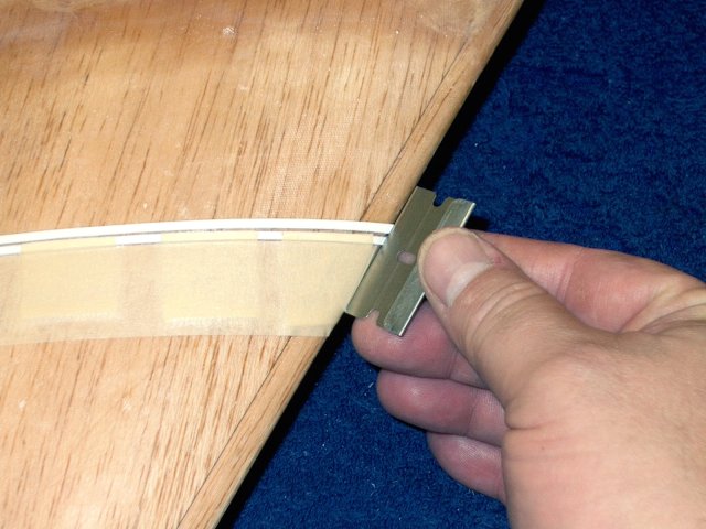
The intake side needed some sanding to
make it flush |
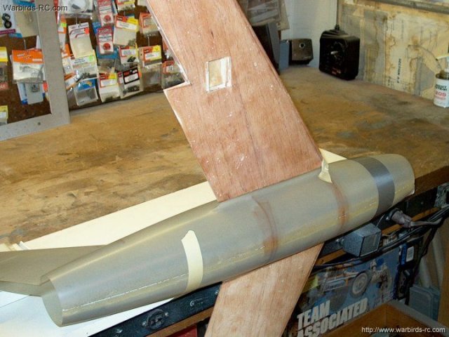
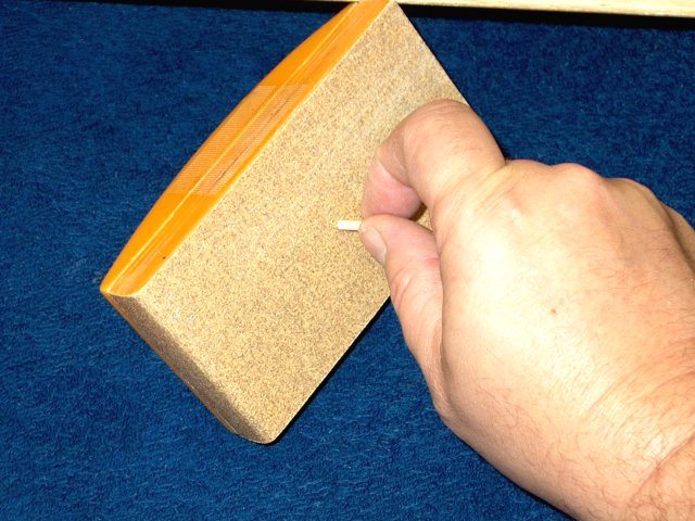
The intake tube is sanded flush to the
fuselage front | |
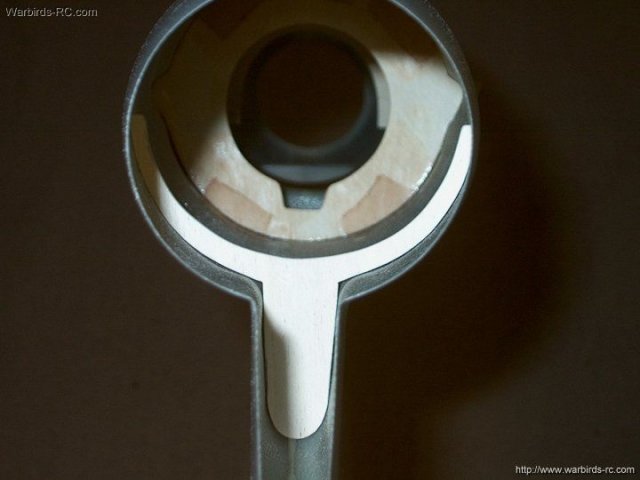
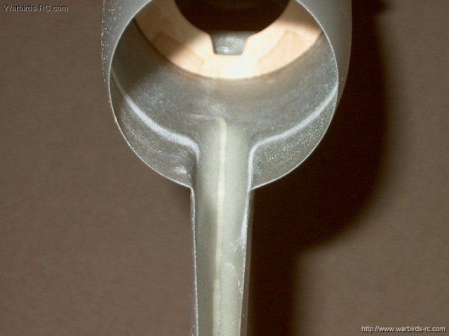
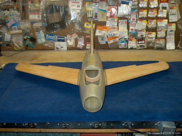
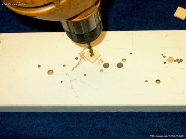
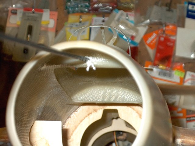
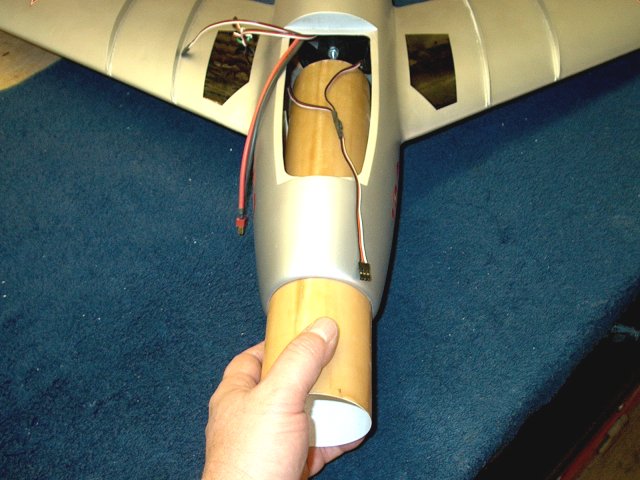
The forward former is installed next and
you may have to sand down the center so the intake tube fits
from front to rear. It is best to do this before gluing the
former in place. Be sure to take off a little at a time and
deepen the center. You can use the template to insure it stays
round at the bottom | |
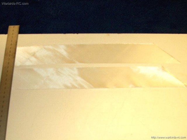
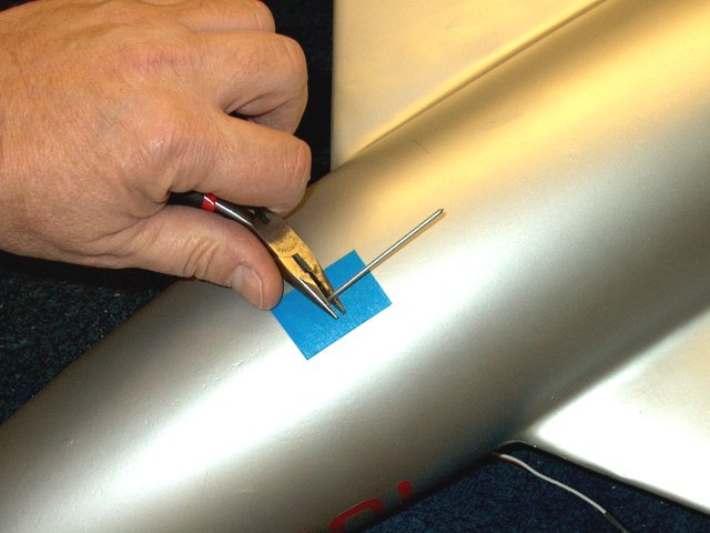
The fuselage is roughed up with 60 grit
sandpaper about 1" wide, centered over the front former
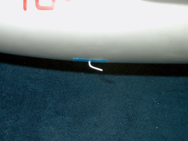
area | |
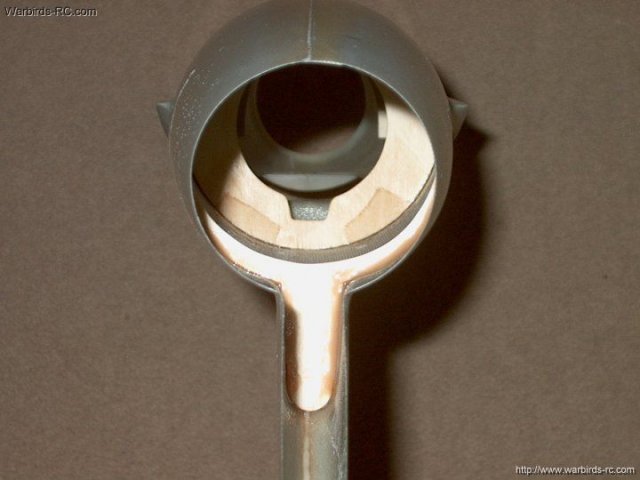
The former is tack glued using 5 minute
epoxy, with the rear of the former on the marks you made
earlier. Then it is glued and glassed in place with 1" wide x
6 1/2" wide strips of glass cloth. Crosscut your cloth at 45
degrees from the weave so it can accordion easily and be
shaped to fit around the curved area. Clean up any excess
epoxy | |
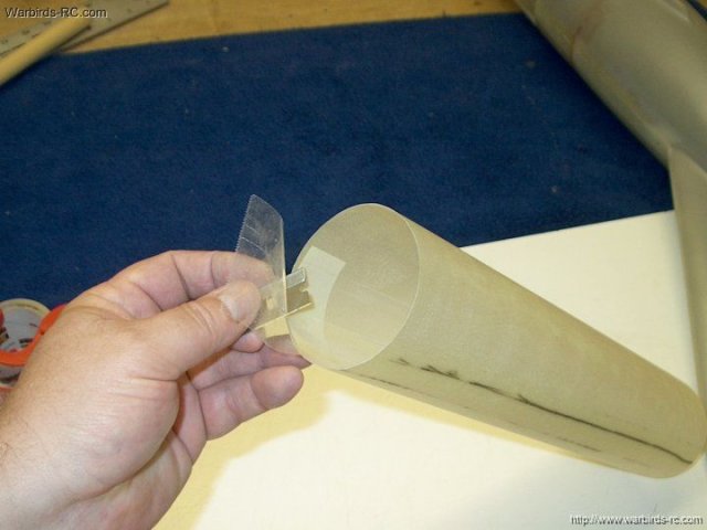
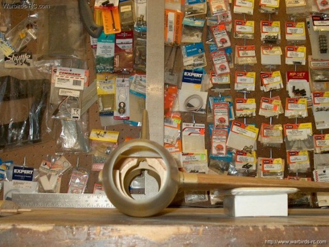
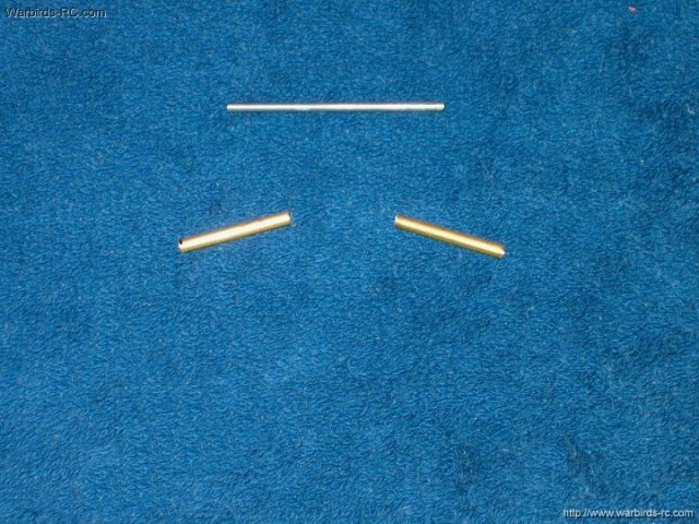
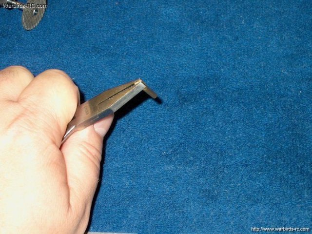
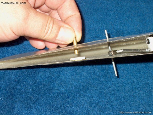
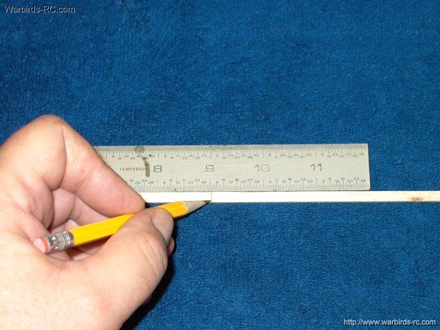
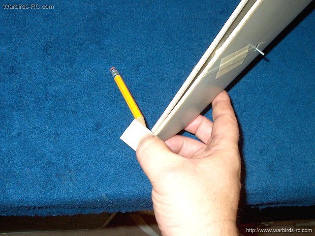
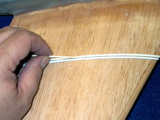
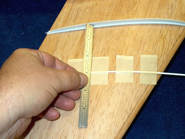
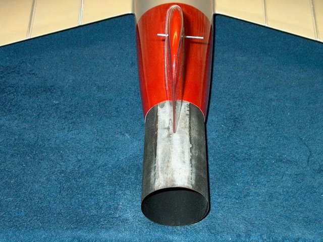
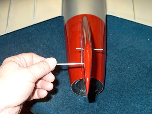
For the MF480, one end of the exhaust tube
is lightly trimmed to straighten the cut from the
manufacturer. If you are using a larger fan, omit this and the
next several steps and proceed to glassing
| |
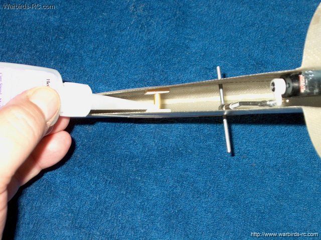
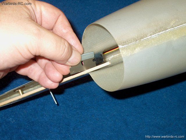
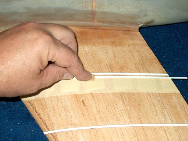
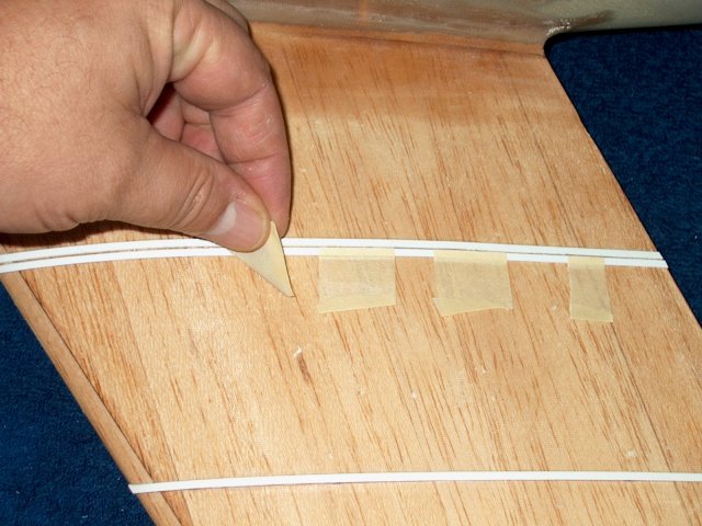
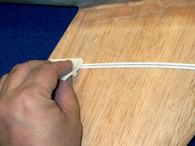
The smaller end is taped flush using
masking tape | |
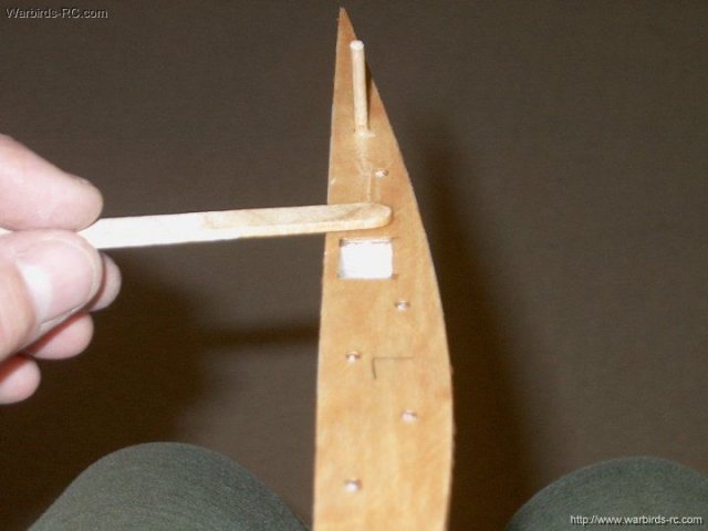
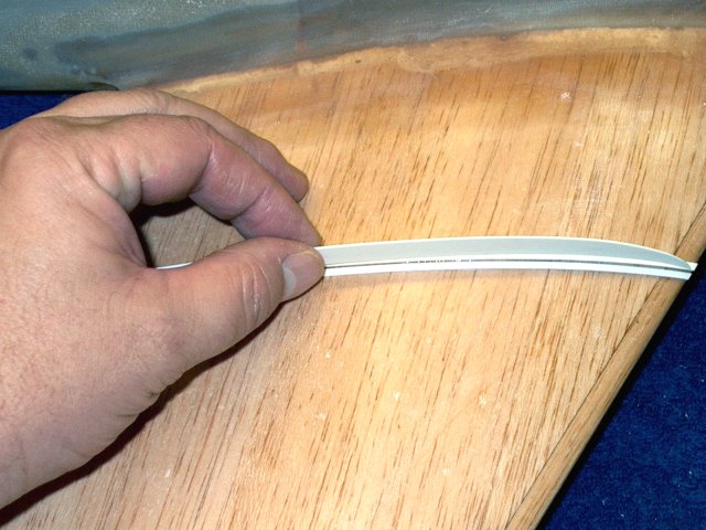
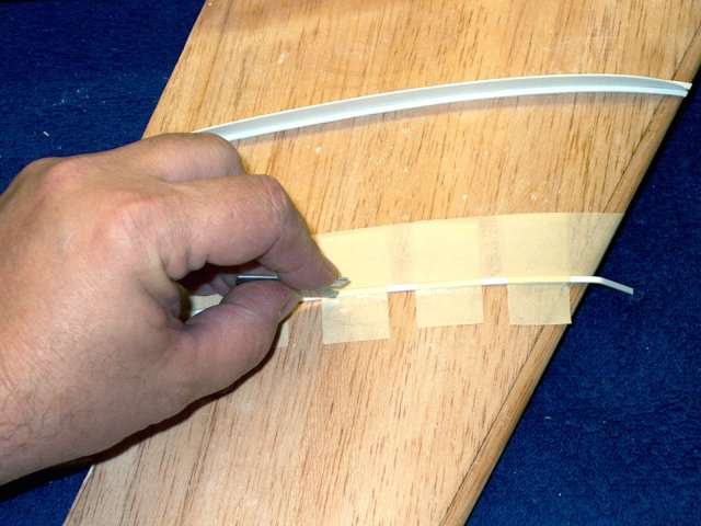
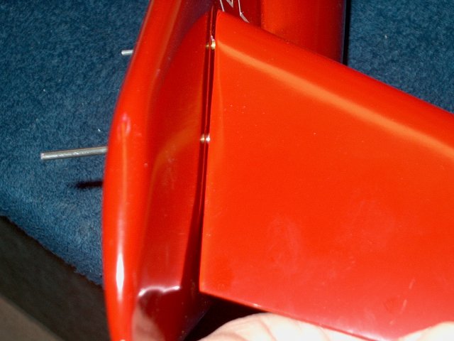
A piece of masking is used to "space" the
duct away from the fan housing. This is to allow room for a
smaller plastic fim exhaust duct to be installed later and is
only for the Minifan 480. For the larger fans, you can omit
this step | |
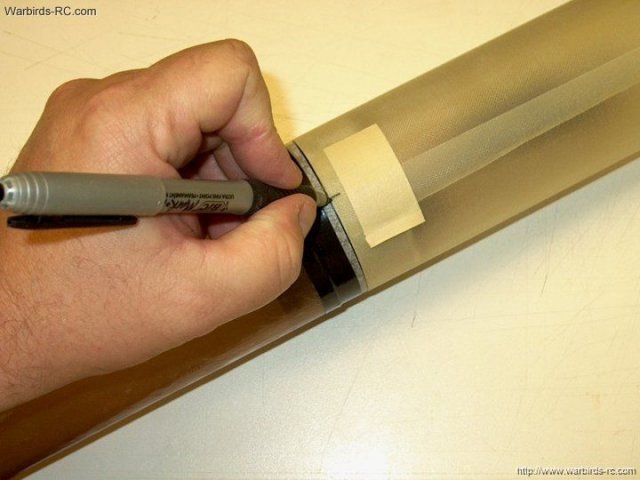
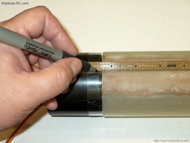
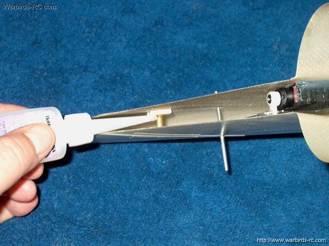
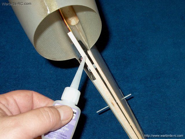
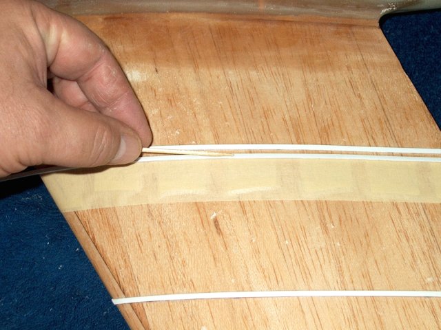
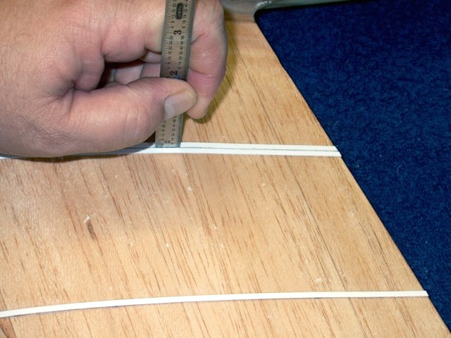
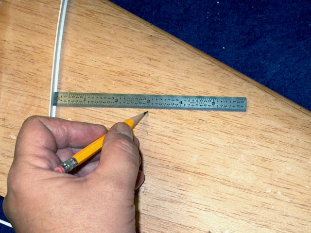
For the MF480, the duct is installed on
the housing and taped tight. Then a mark is made on the
unevenly cut side of the duct at the overlapped area
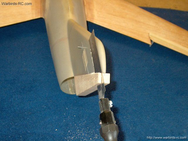
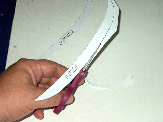
| |
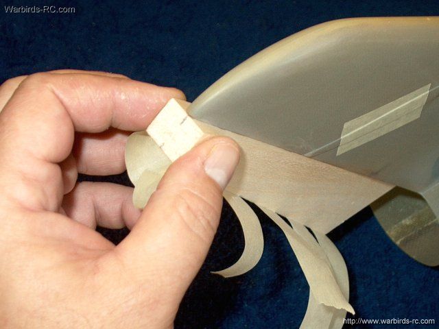
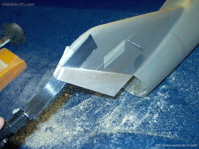
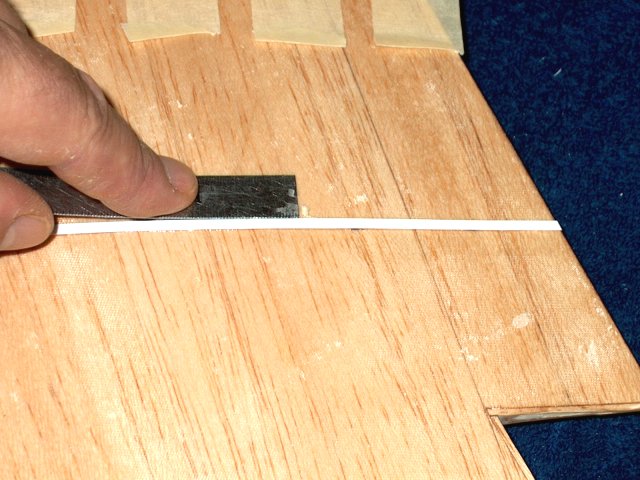
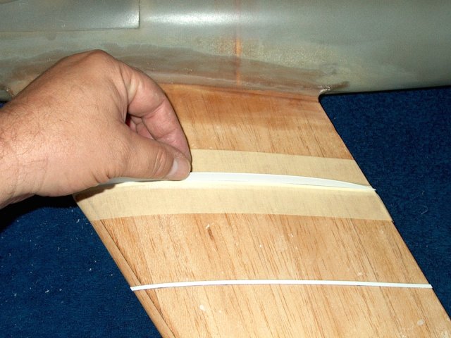
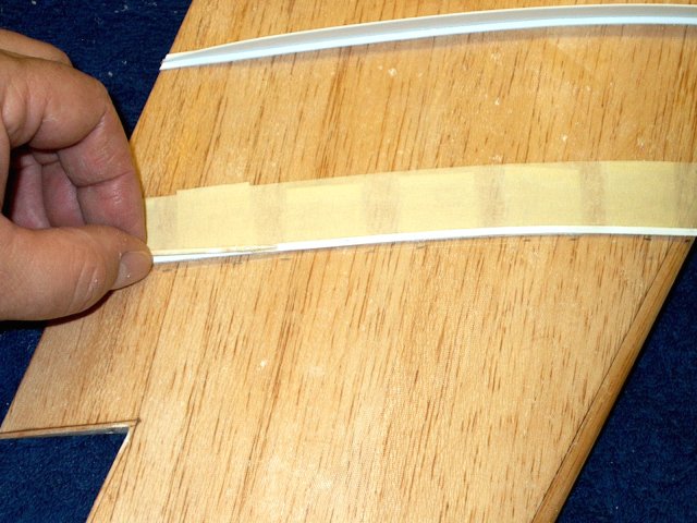
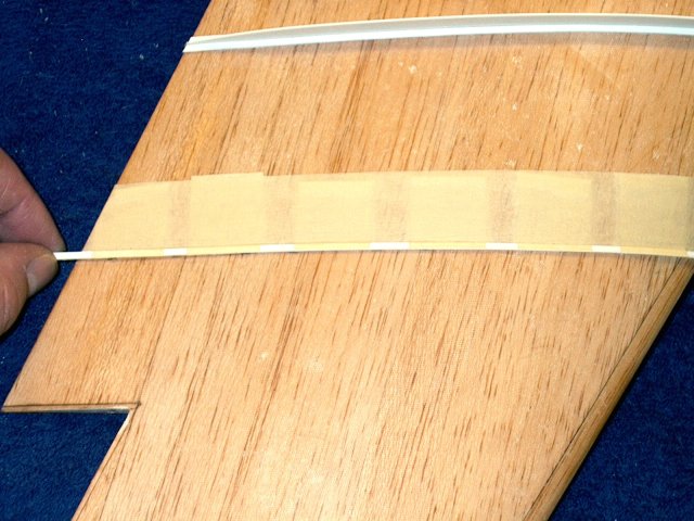
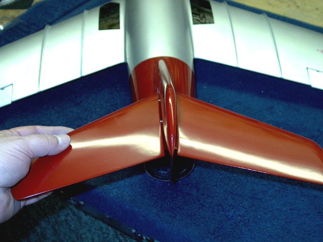
The other uneven side of the duct is cut
away from the mark | |
The piece is shown removed
| |
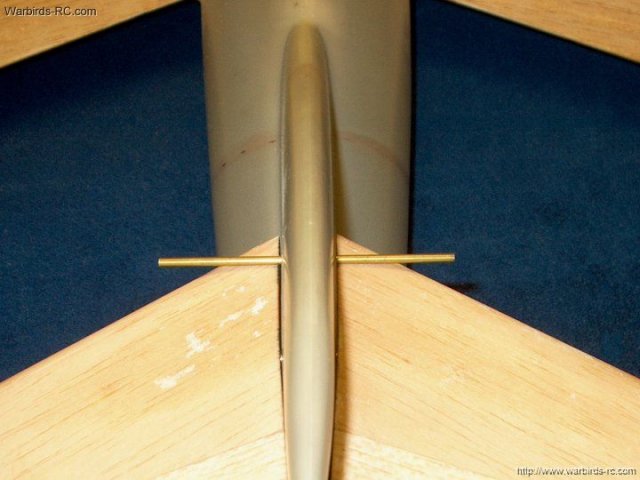
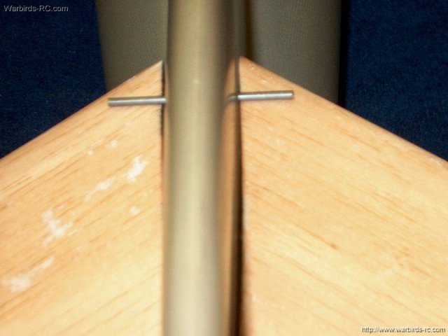
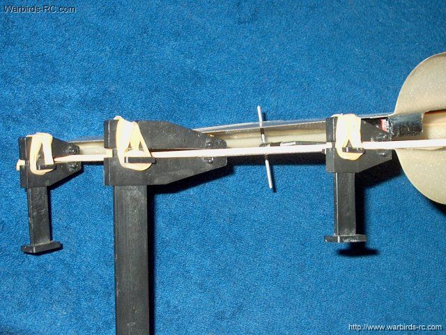
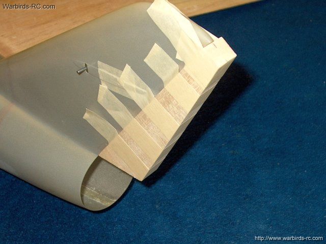
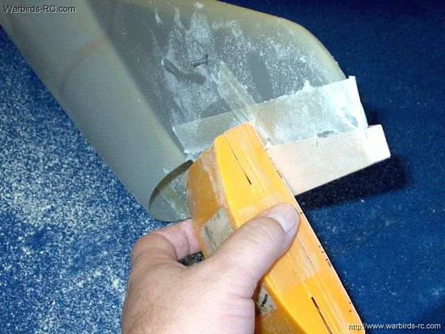
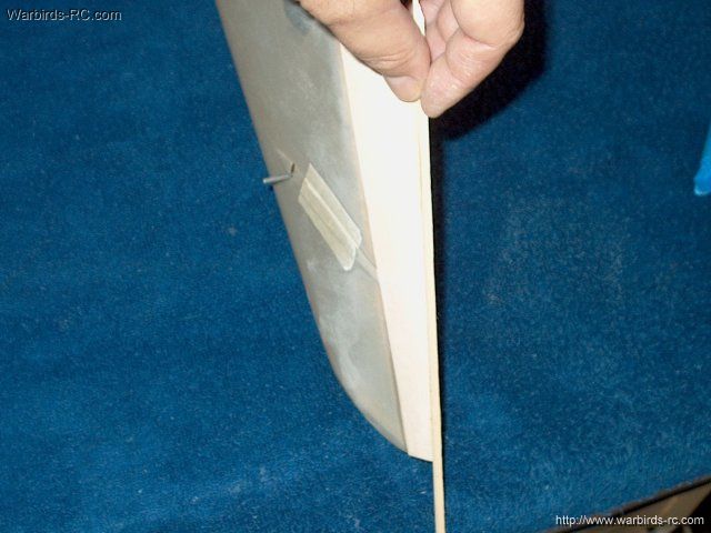
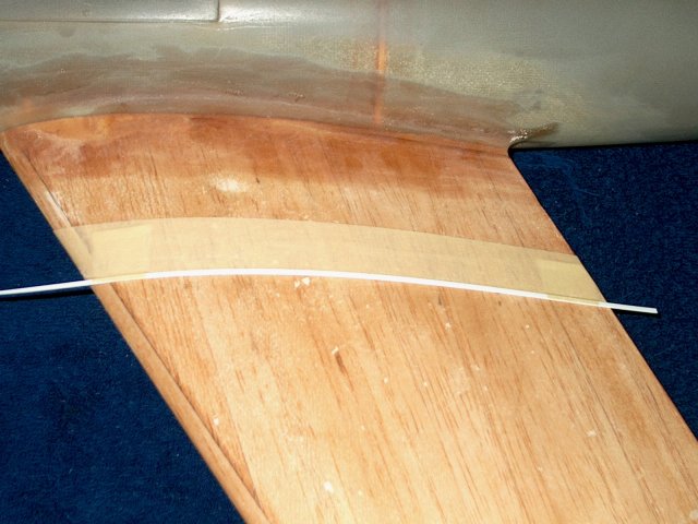
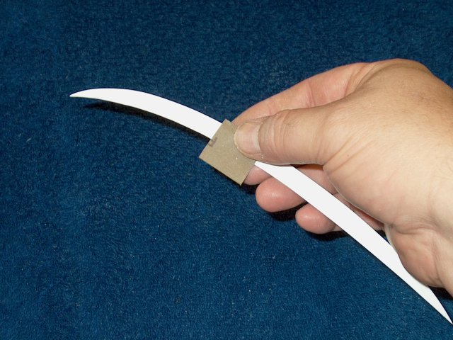
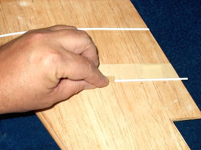
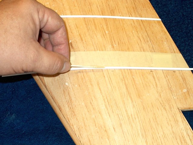
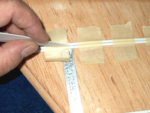
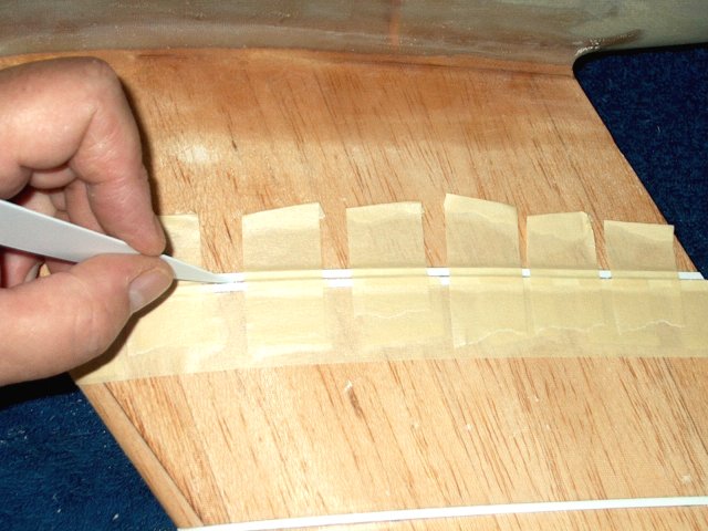
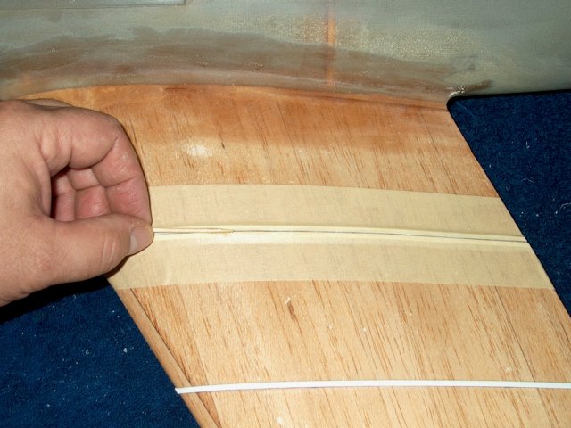
The tube is held flush at the ends with
masking tape. If necessary, lightly sand the two edges so they
are flush all the way down the tube
| |

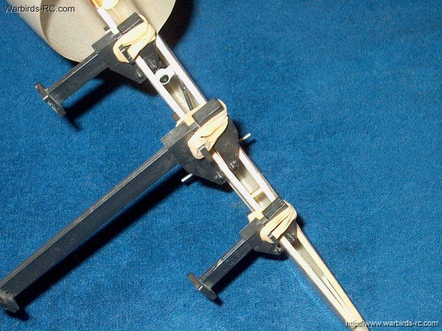
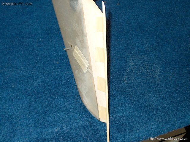
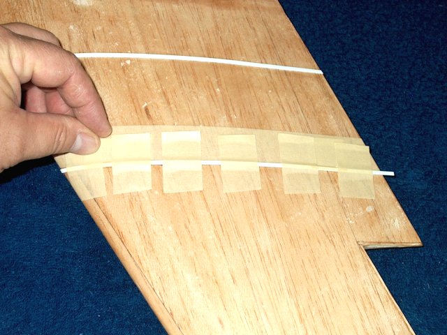
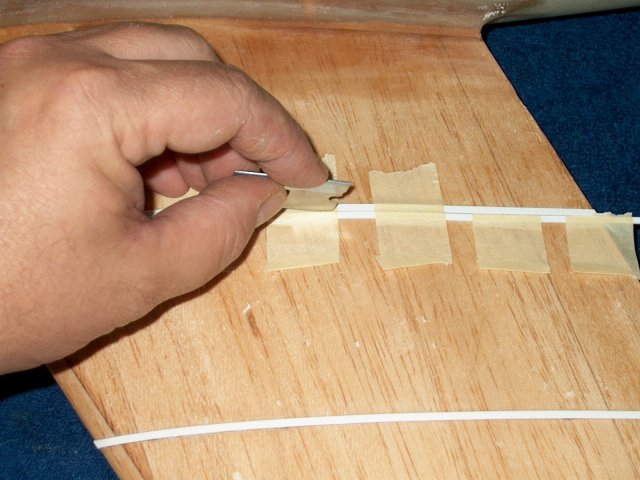
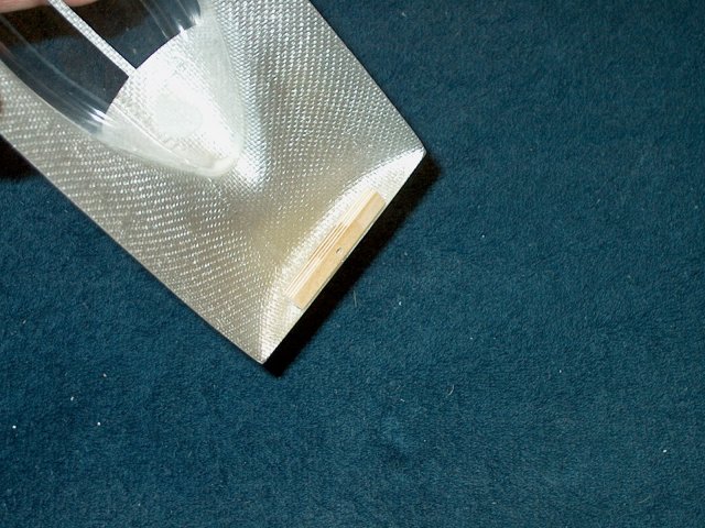
Packing tape is used on the inside to hold
the two edges flush | |
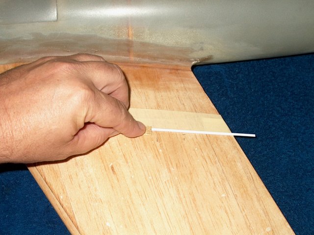
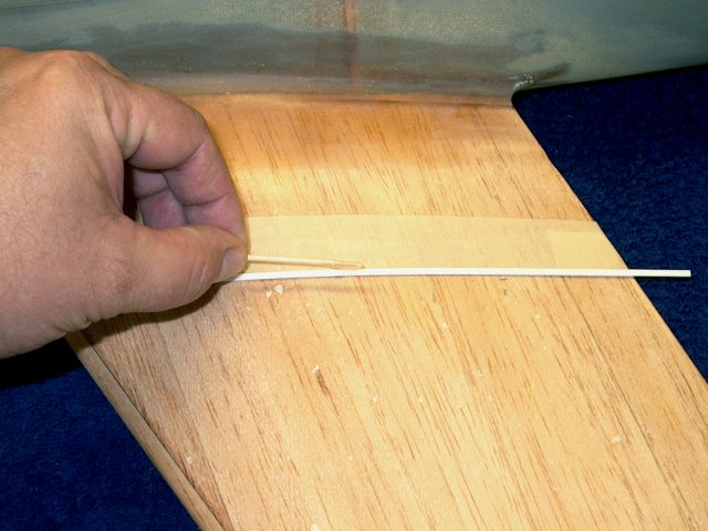
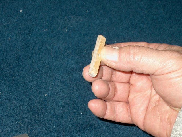
A wooden dowel is used to push the packing
tape down on the inside where you cannot reach
| |
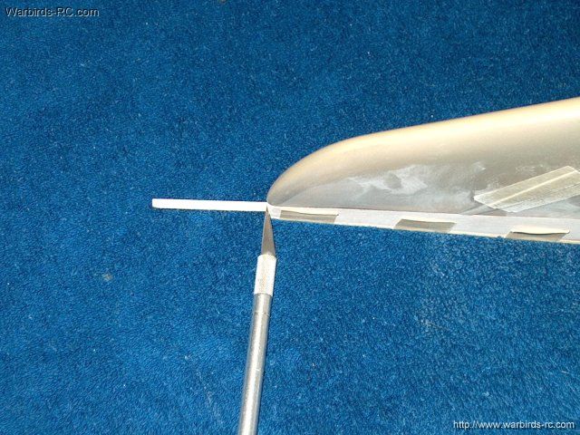
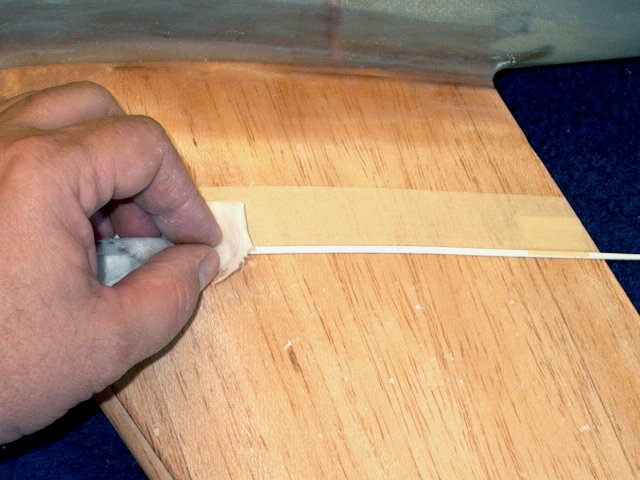
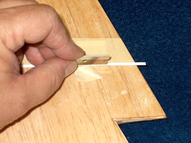
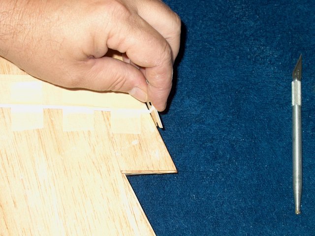
The excess tape is removed with a
razor | |
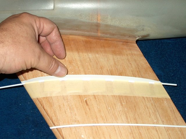
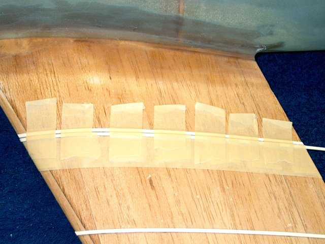
The outside masking tape is removed and a
couple of layers of masking are used on the inside ends for
drips | |
The tube is taped to your working surface
so it is easier to glass | |
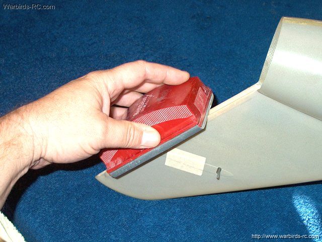
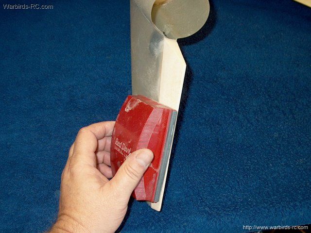
An area is sanded about 3/4" wide on each
side of the seam | |
Glass cloth shown is cut to about 1
1/2" | |
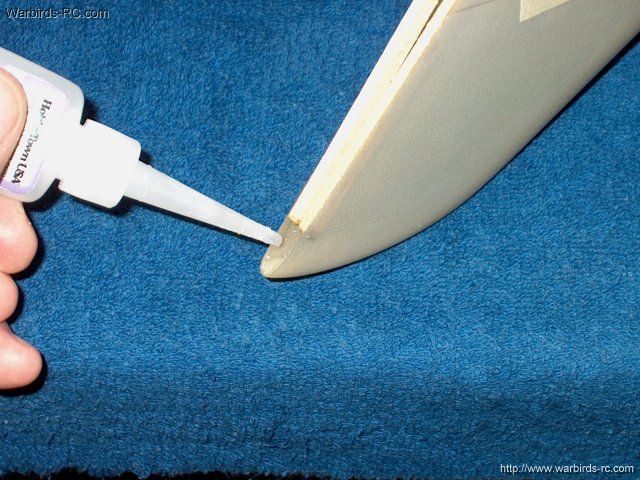
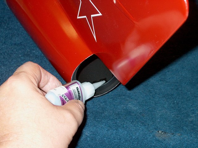
Epoxy resin is applied to the seam area of
the exhaust tube | |
The cloth is layed over the resin area and
pressed down | |
Resin is brushed on the top of the cloth
to make sure it is saturated | |
The excess resin is removed with a
spreader and the tube is left to set
| |
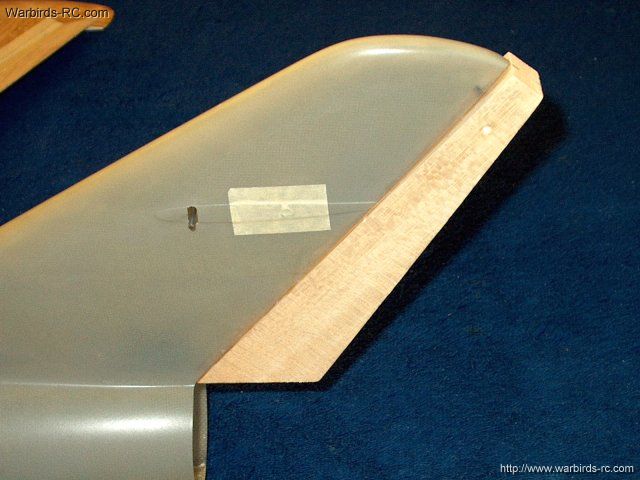
The seam was sanded to remove excess epoxy
and keep it light | |
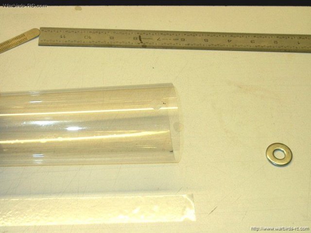
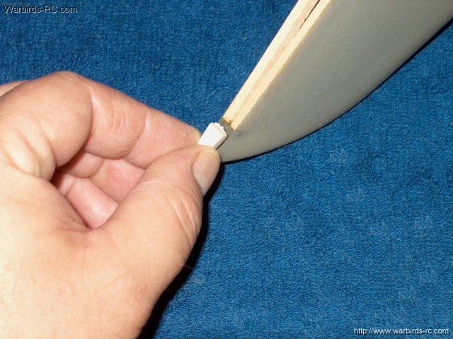
A ring is made from 1/16" ply to fit in
the end of the fiberglass tube and the inside is cut to 55mm
diameter | |
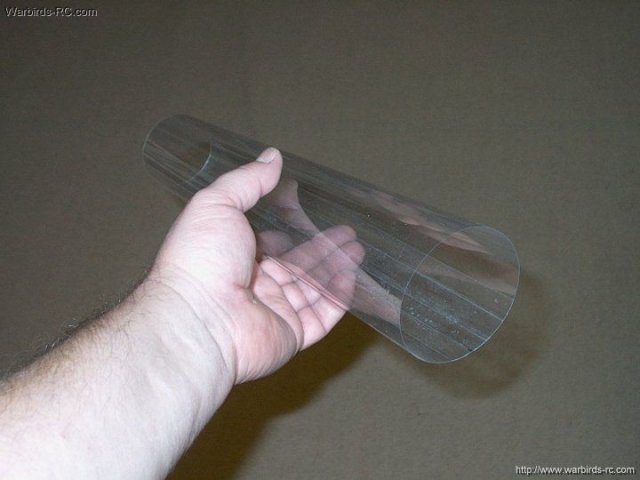
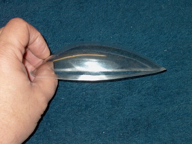
A piece of clear 5 mil Dura Lar used as an
inner thrust tube for the Minifan is cut oversized, then
inserted in the glass tube at the fan side and trimmed flush
to the end | |
Masking tape is used to hold the inner
liner flush with the fan end | |
The ply ring is installed and the inner
thrust tube is cut flush with the fiberglass tube at the
exhaust end | |
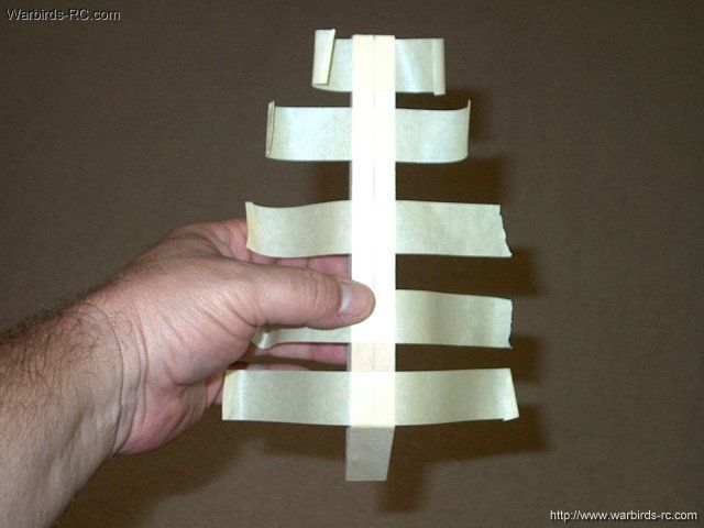
Apply masking to hold the tube in place,
then cut a 1" wide piece of clear packing tape and seal the
tube seams inside and out | |
Inner thrust tube assembly
completed | |
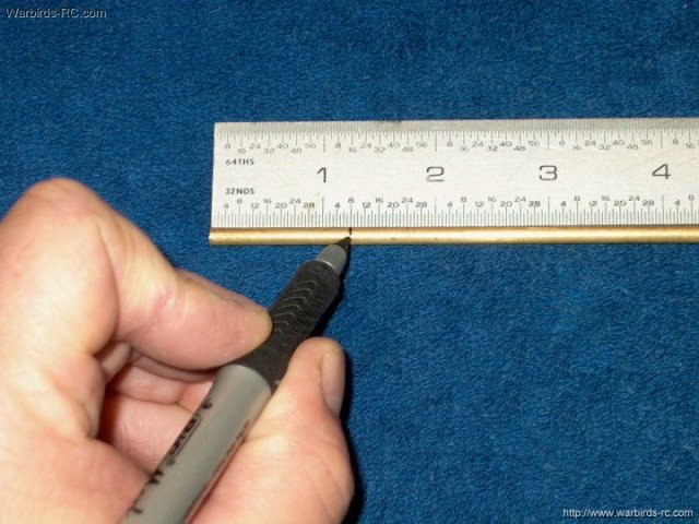
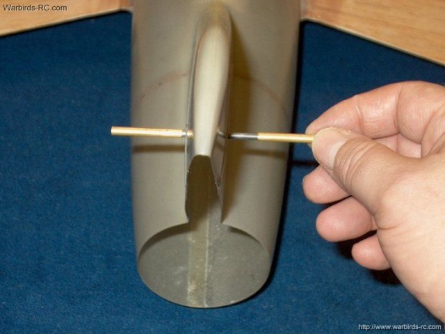
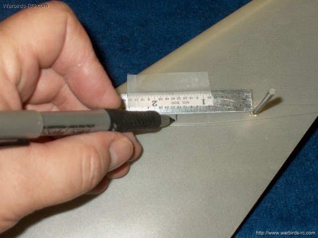
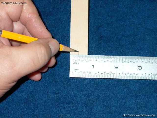
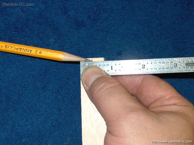
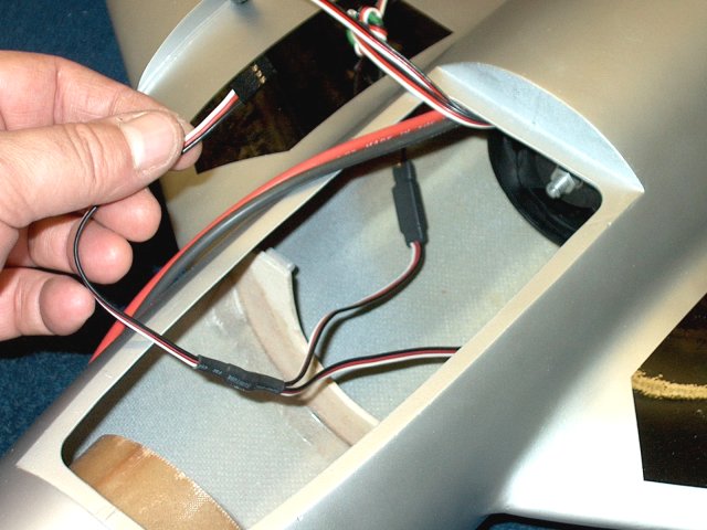
A mark is made 1/2" from the edge of the
tube | |
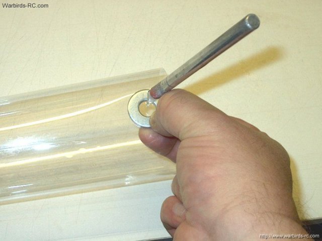
3/8" Washers on each side of the plastic
make cutting a hole easy | |
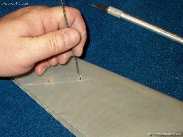
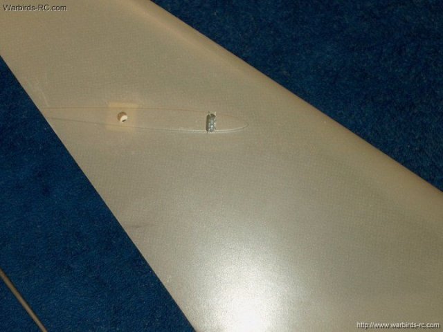
Hole is shown cut for ESC wires
| |
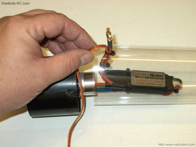
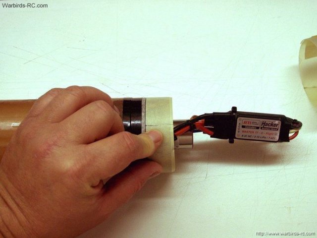
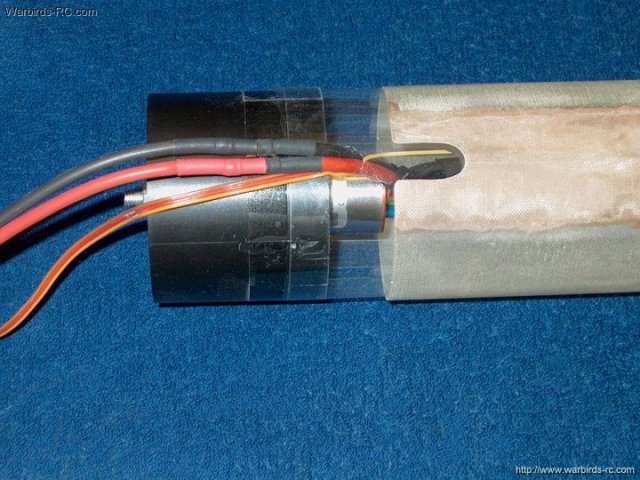
Wires are inserted through the hole
| |
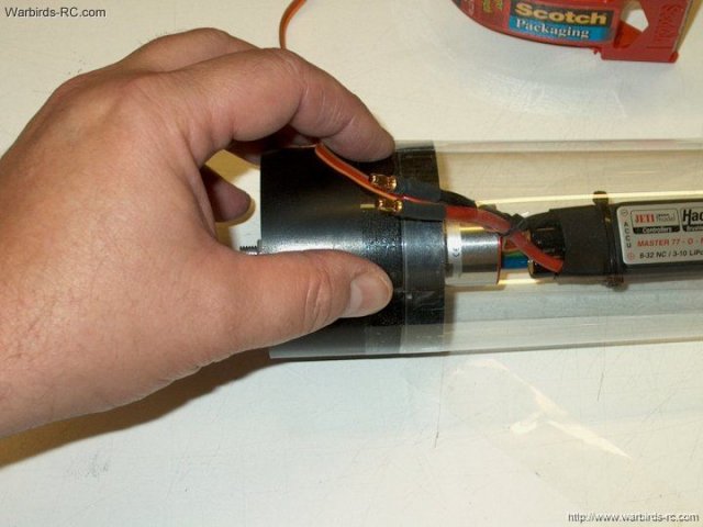
The tube is slid 1/2" over the fan housing
and taped in place | |
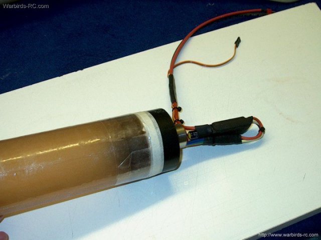
Fan assembly and inner thrust tube
completed | |
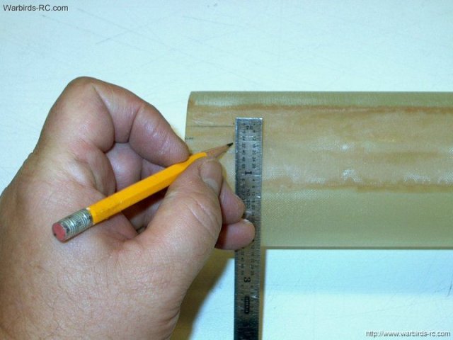
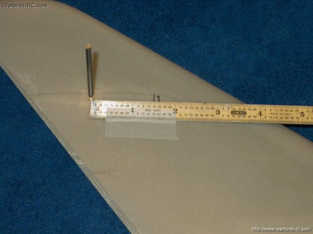
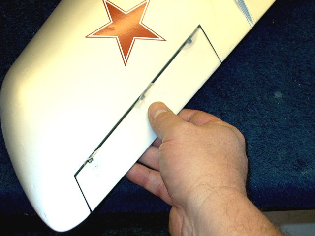
The fiberglass thrust tube is marked to
slot it for the ESC wires | |
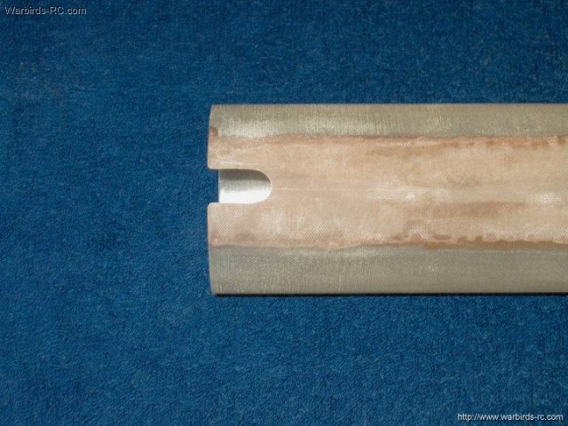
The slot is 7/8" deep and 1/2" wide and
rounded at the edges | |
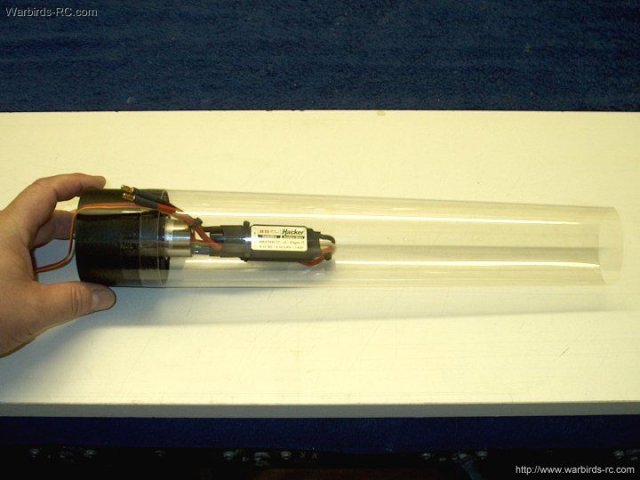
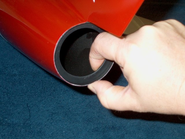
The fan asembly and inner thrust tube
slide into the outer glass thrust tube
| |
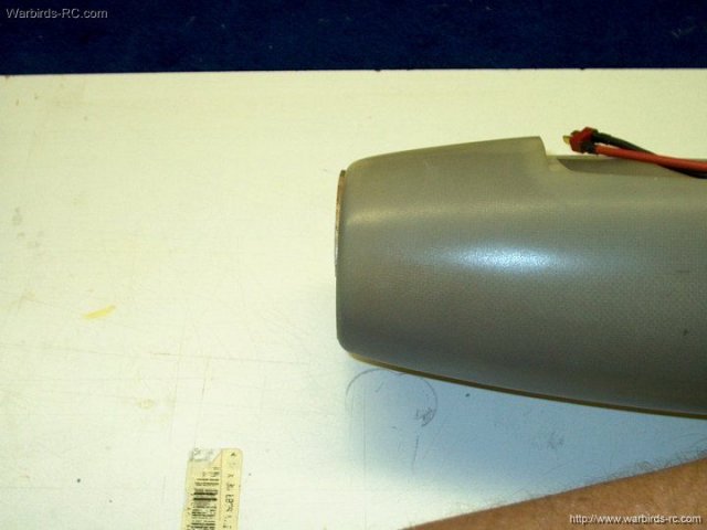
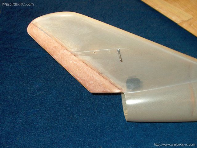
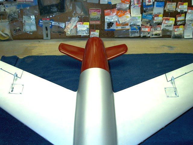
The tail end of the fuselage should be
checked for round and sanded straight if necessary
| |
Tail is shown sanded and ready
| |
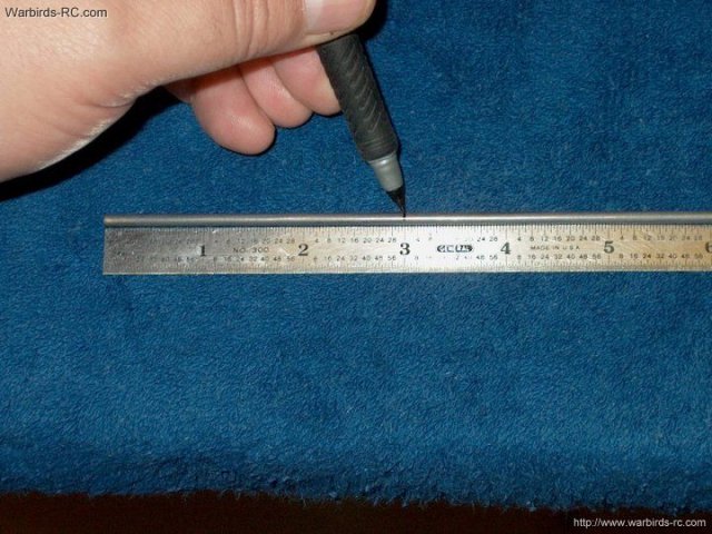
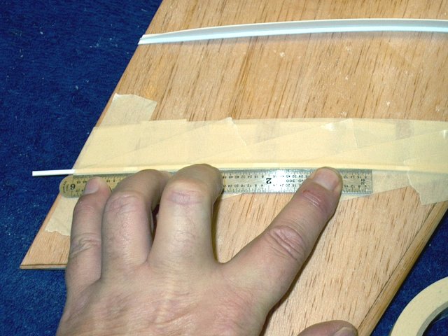
Location marks are made 4 3/4" from the
tail for the rear former | |
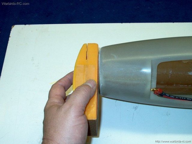
Fine sand the former until it fits flush
| |
60 grit sandpaper taped to your finger
makes it easy to sand the inside of the fuselage area for the
rear former | |
Once sanded, clean the dust off with
alcohol and a towel | |
Thirty minute epoxy was used to glue the
former in place and a fillet mix of epoxy and fiberglass mil
was applied to the joint | |
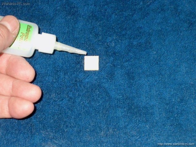
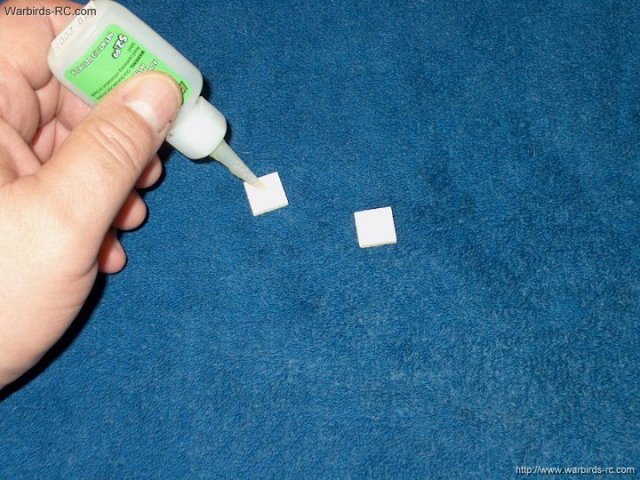
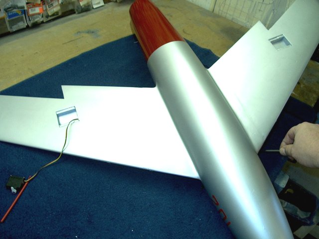
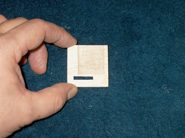
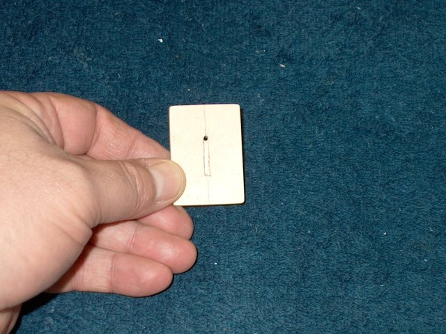
Coat four of the 1/8" thick x 1/2" ply
squares with CA on one side | |
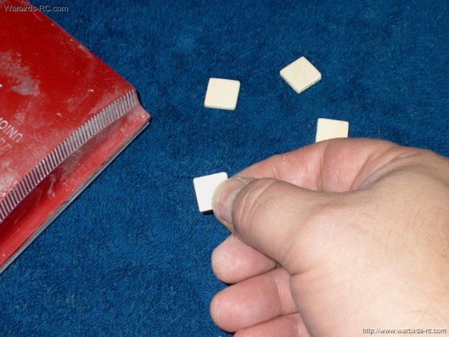
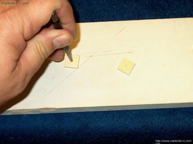
Sand the CA side and round the corners on
the squares | |
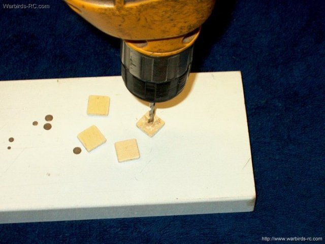
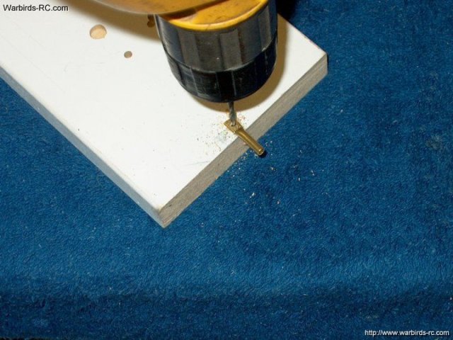
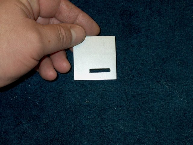
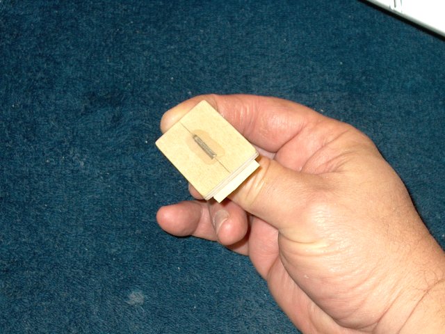
Drill a 1/8" hole in two of the squares
and a 3/16" hole in the other two squares
| |
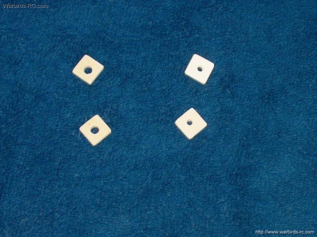
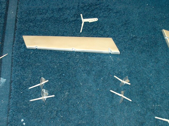
Photo shows all four squares prepared and
ready to use as retainers | |
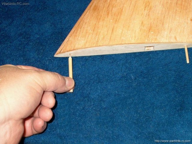
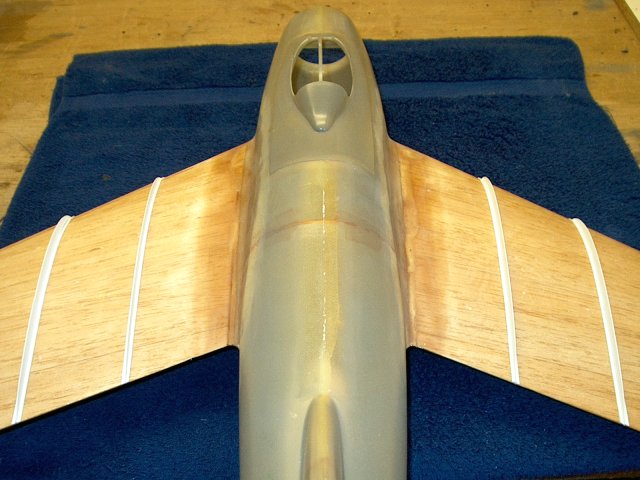
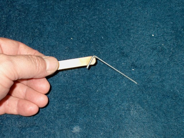
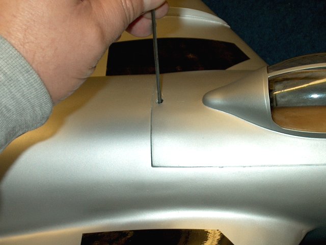
The 3/16" and 1/8" wood dowels are pressed
into the wing to make a guide hole. Keep the dowels square to
the root | |
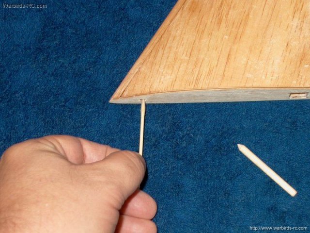
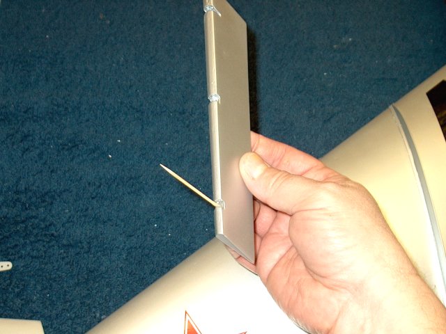
Epoxy is applied to each hole using a
toothpick | |
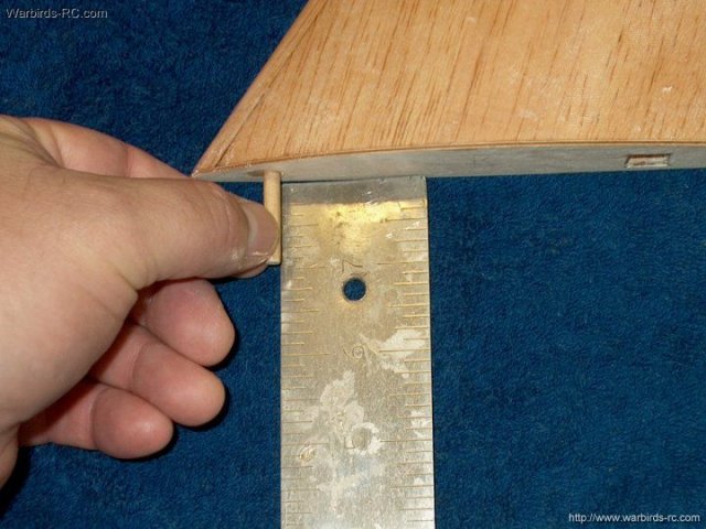
The wood dowels are inserted and kept
square with 1" protruding | |
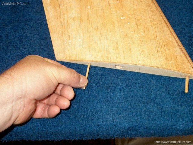
The dowels for the second wing are
installed | |
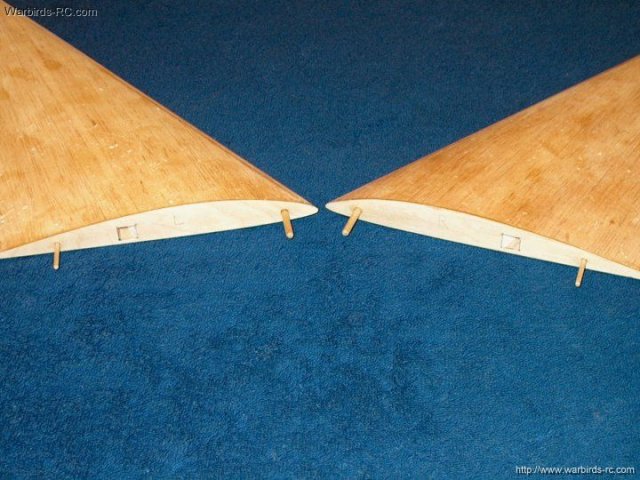
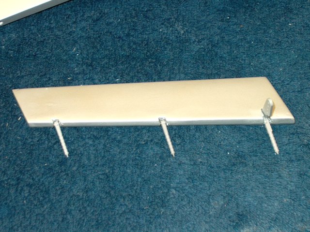
Photo shows all wing dowels installed
| |
The wing root is roughed up with 60 grit
sandpaper | |
Wing root is ready to final prep for wing
installation | |
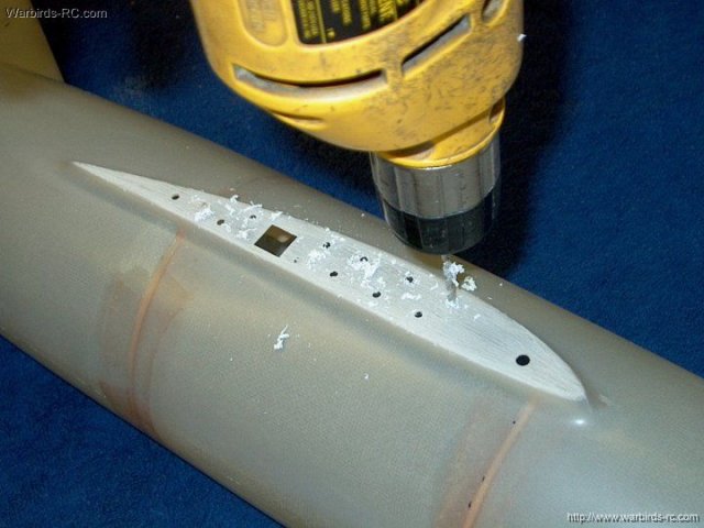
Drill holes as shown with a 1/8" bit to
allow for better glue adhesion | |
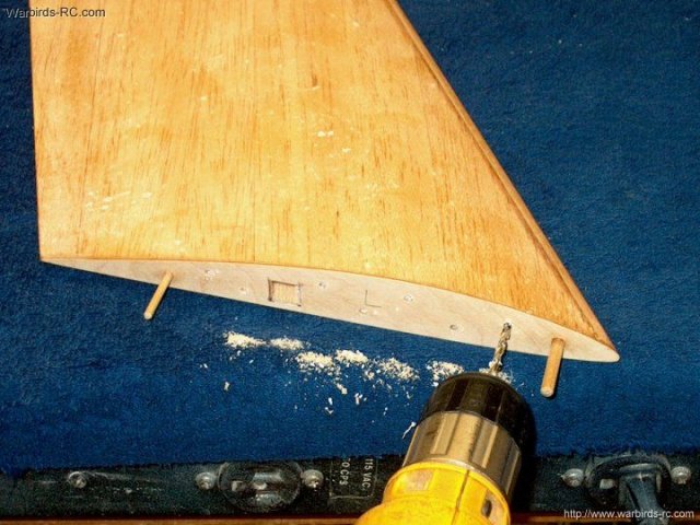
The wing spar is also drilled as
shown | |
The outside of the fuselage and wings are
covered with masking tape to catch the overflow when
gluing | |
Wing and Fuselage root shown ready to
epoxy | |
Wing was temporarily installed and checked
while the fuselage is squared up. The wing root when flush to
the fuselage was in the correct position
| |
Clear epoxy is applied to the wing root
and left to soak in...do not apply epoxy to the wood
dowels | |
Epoxy is thickened with fiberglass mil and
spreaded thick as shown | |
The forward and rear wood dowel holes are
cleaned with a Q-tip | |
The wing is installed on the
fuselage | |
The wing is pressed down in place and
excess epoxy is cleaned with denatured alcohol and a paper
towel | |
Make sure the wing is flush to both the
root and the bottom of the fuselage. You can slide the ply
squares over the wood dowels on the inside to help hold the
wing to the fuselage | |
Remove the tape from the wing and fuselage
before the glue sets | |
Allow some time for the epoxy to
set | |
Once the epoxy has set but is still soft,
you can check the rivots that were formed at the drill points.
Use your finger to round them out and slightly flatten them
for a better hold as shown | |
Apply epoxy to the other fuselage root and
wing | |
Clean the wood dowel holes out as
shown | |
The wing is installed on the fuselage
| |
Seat the wing, clean up the excess epoxy
and remove the tape as with the first wing, then allow some
time for the glue to set | |
Both wings are shown installed
| |
The wing seams are filled with a
lightweight body filler and sanded to shape
| |
A piece of 60 grit sandpaper is used to
rough up the fuselage area for glassing. Sand about a 1" wide
area from front to back | |
Strips of 2-5oz cloth are cut 2" wide in
preparation for glassing | |
Epoxy is applied to the side of the
fuselage and wing area | |

The glass cloth is placed in position and
excess epoxy is removed | |
Wing to fuselage area shown glassed and
allowed to set up | |
The bottom of the wing area is glassed the
same way | |
Strips of glass cloth are applied to the
area. I used 2 oz fiberglass cloth on the top for a nicer
finish and 5oz cloth as shown on the bottom for
strength | |
The bottom of the wing is shown glassed.
Sand and blend the seams | |
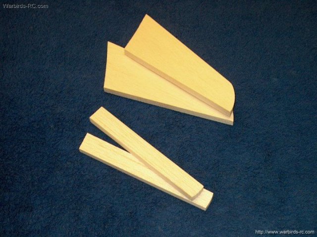
The horizontal stab and elevator pieces
are shown in the pic | |
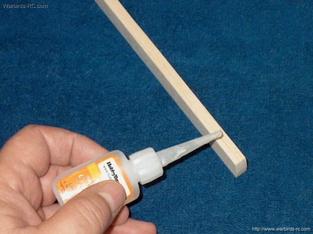
Thin CA is applied to the leading edge of
the Elevator | |
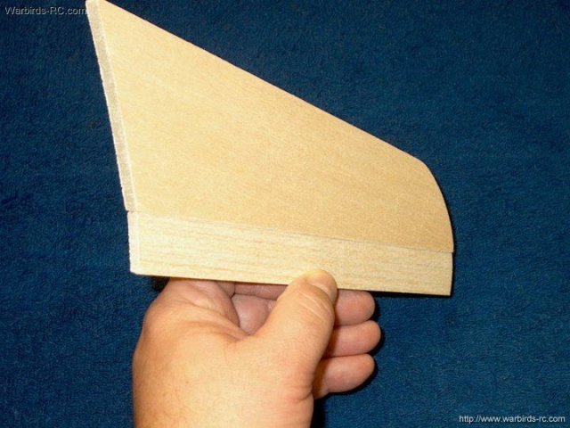
The Elevator is installed centered over
the edge of the Stab and flush with the inside
| |
The elevator is mounted to the second stab
in the same manner | |
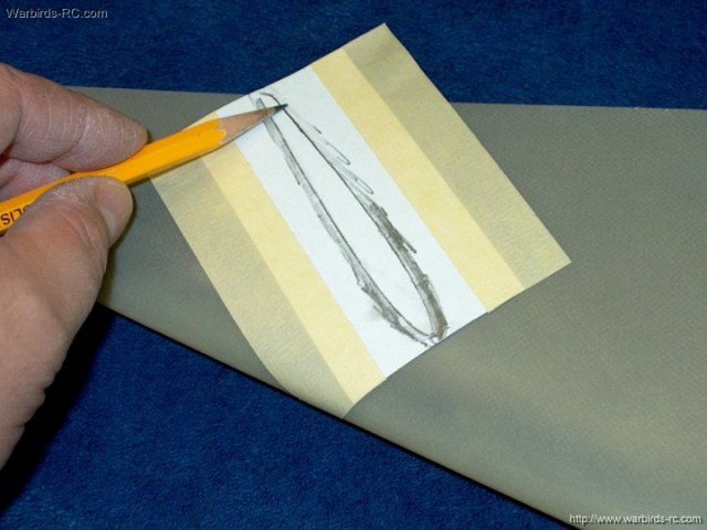
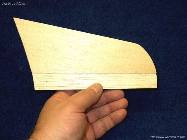
A piece of paper is taped to the vertical
stab at the Elevator location and the airfoil shape is traced
out as shown | |
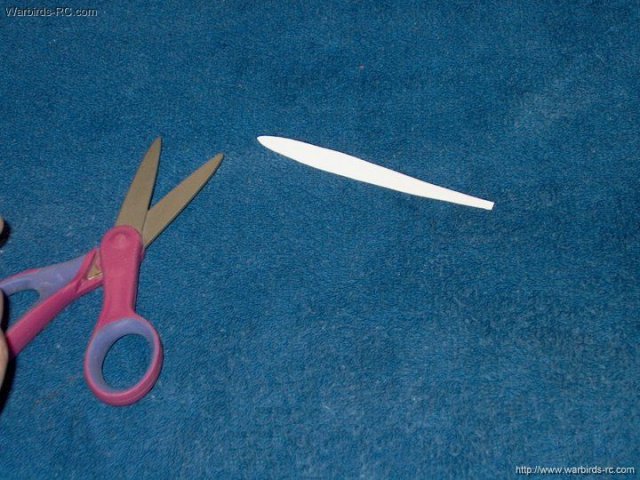
The shape is cut out from the
tracing | |
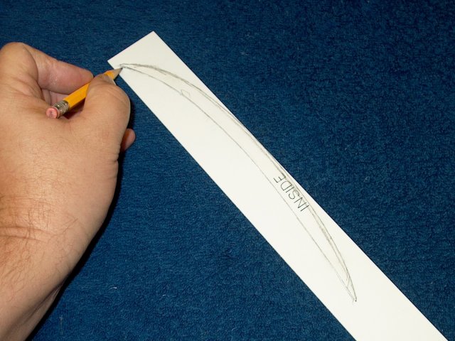
A center line is marked down the leading
edge of each Flying Stab | |
A center line is drawn down the leading
edge at the marks | |
Center line is drawn on the second stab as
shown | |
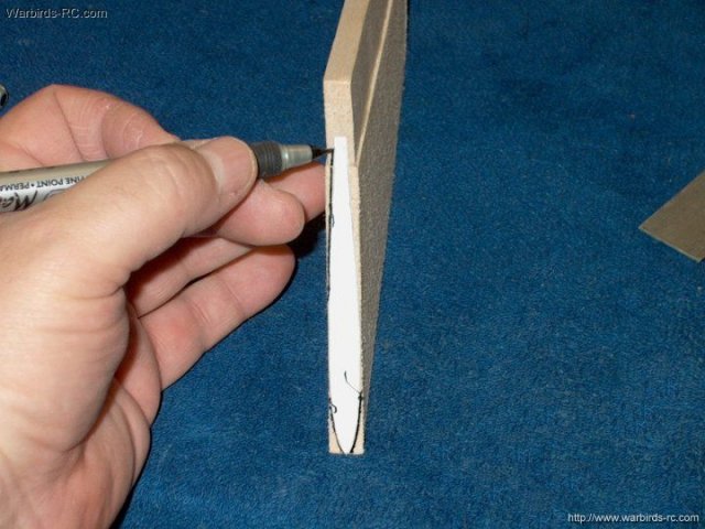
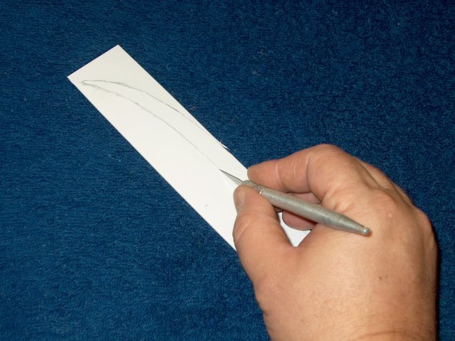
The cut out pattern is used to trace the
airfoil shape to each stab inner root
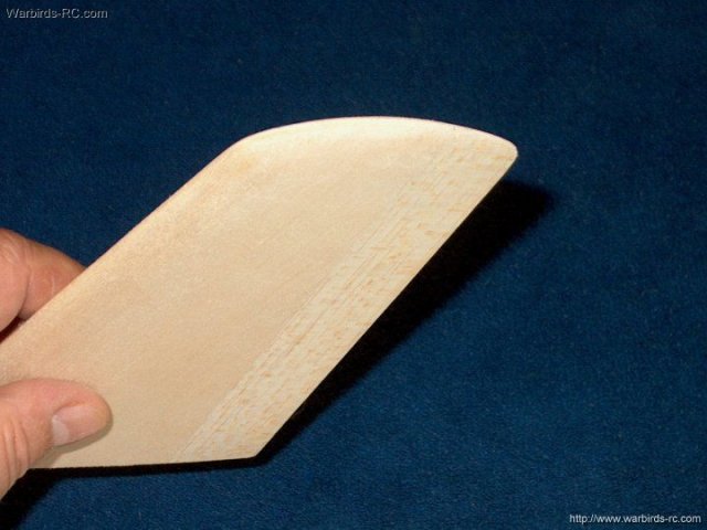
| |
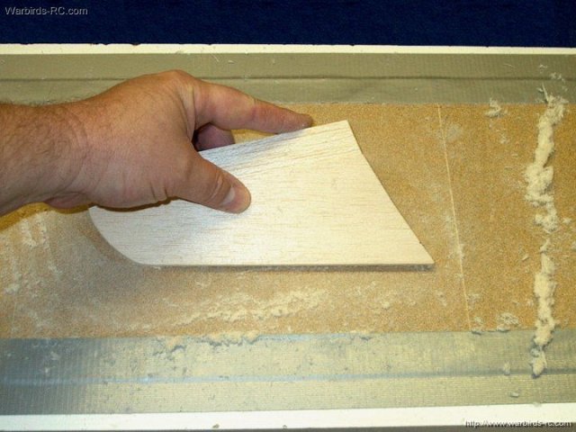
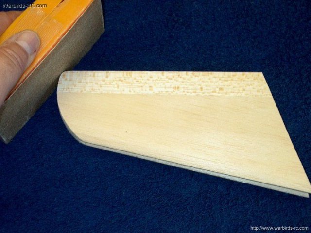
The sanding board is used to form the
airfoil shape and taper the tail to 1/16" thick for each of
the two Stabs | |
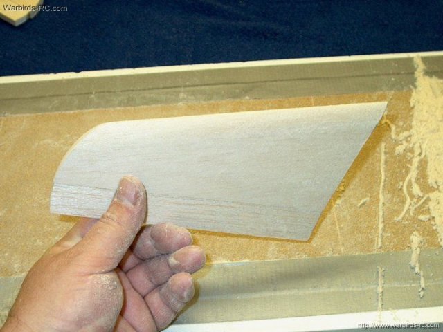
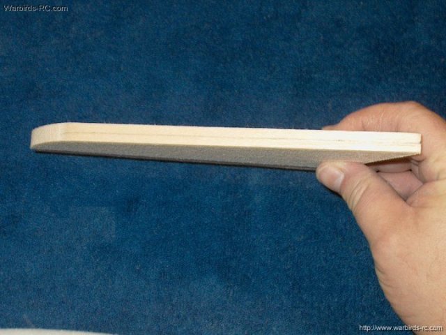
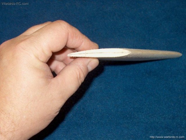
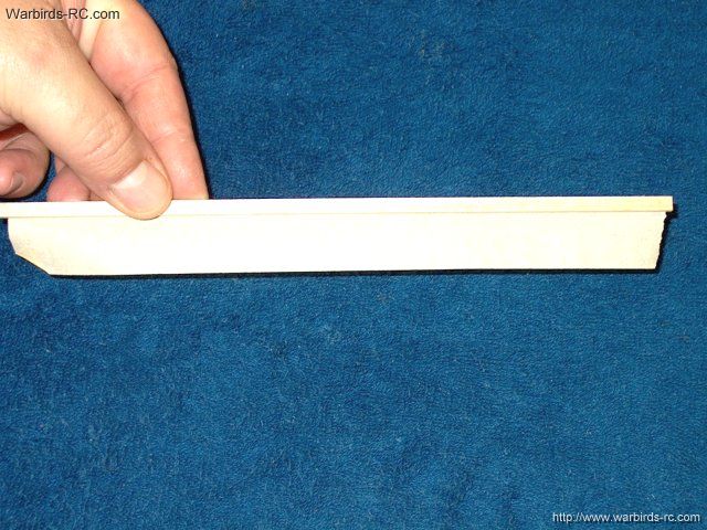
The leading and trailing edge has been
tapered as shown | |
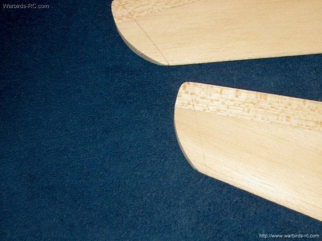
Both Stabs are aligned on top of one
another and the inner rear edge is shaped to align itself with
the root (top right), then the outer side is shaped with a
sanding block as shown (left) | |
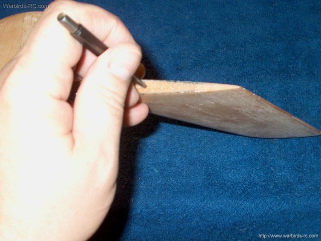
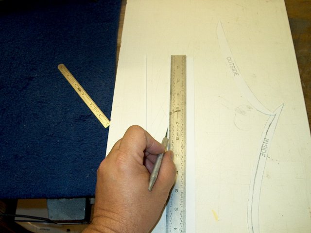
A center line is drawn down the outer edge
of each stab | |

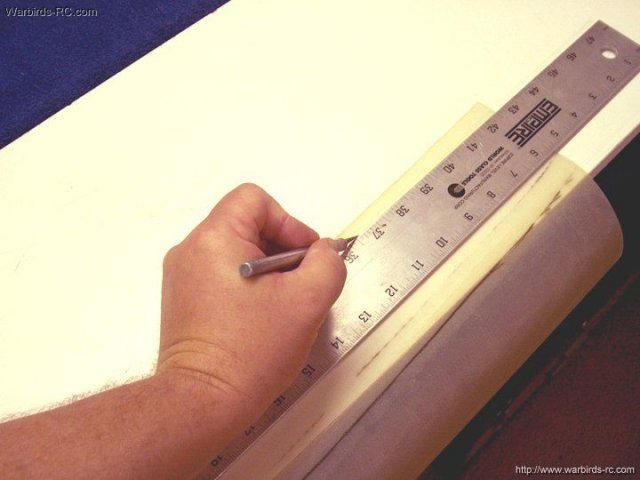
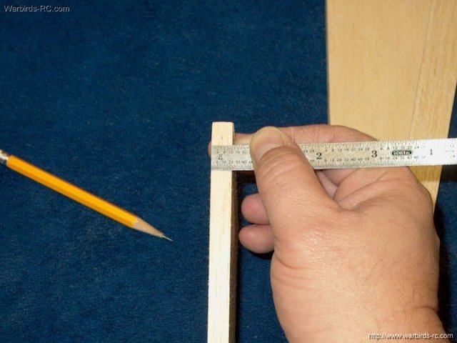
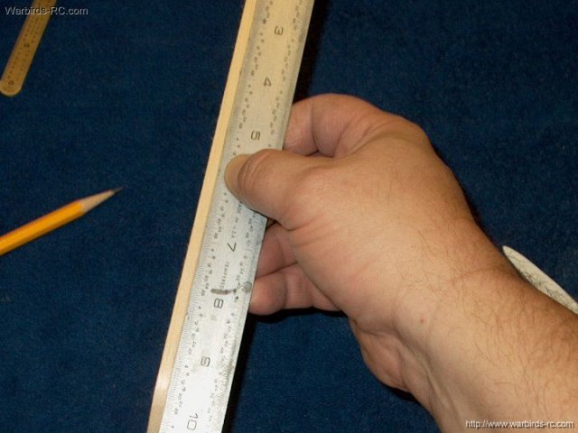
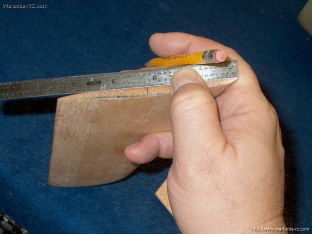
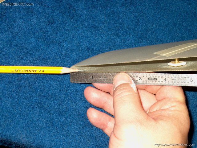
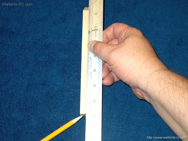
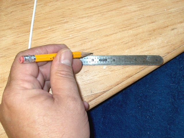
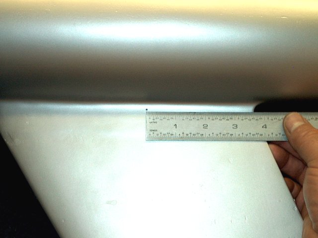
A ruler is used to measure 6 1/2" from the
inside root | |
Lines are drawn as shown on each
stab | |
A sanding block is used to taper the stab
outer tips in the same way the wing tips were shaped. Sand
from the line that was drawn to the tip making an even bevel
| |
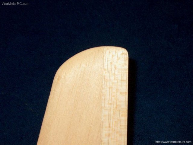
The second stab was tapered as
shown | |
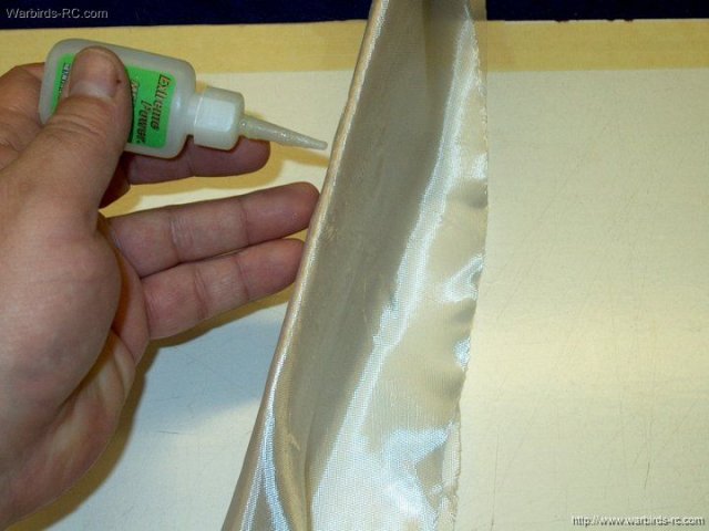
Two pieces of 3/4 oz fiberglass cloth were
cut to overlap and cover both sides of each stab. Use medium
CA to anchor the leading edge as shown and wipe away any
excess glue while pressing the cloth down
| |
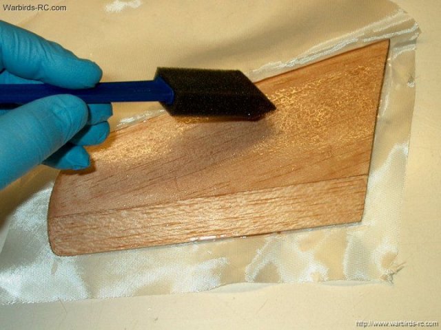
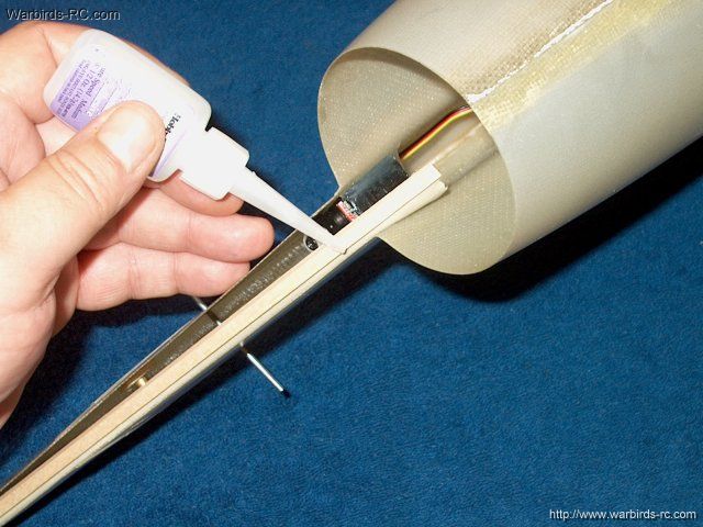
Epoxy finishing resin is applied to the
inside root, leading outer and trailing edges, then to one
side of the stab. The cloth is applied and stretched to remove
wrinkles | |
The other side of the stab is glassed in
the same manner | |
A thin sheet of plastic is used to help
seal the stab and remove the excess resin without disturbing
cloth position | |
The plastic sheet is applied to the other
side of the stab and the excess resin is removed. Once done,
the plastic edges are trimmed as shown and the stab is placed
in a phonebook while the resin sets
| |
The second stab is glassed in the same
manner as the first | |
It is shown placed in plastic. Insert into
a phonebook while the resin sets | |
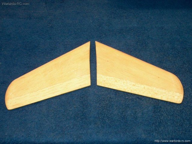
Horizontal Stabs are sanded and ready to
install | |
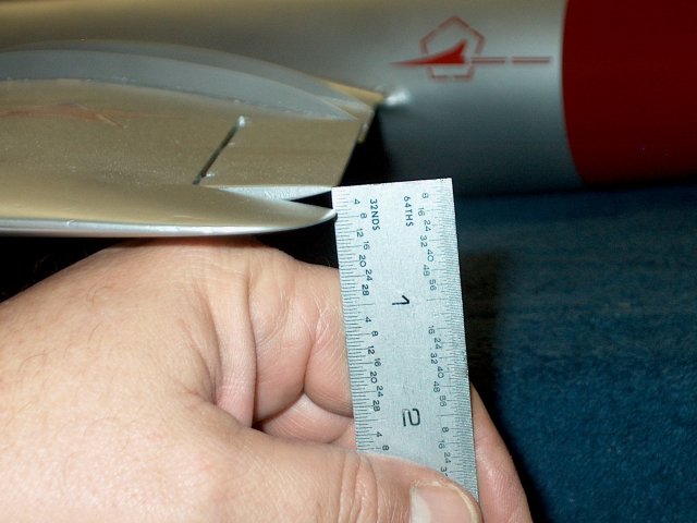
Make a center line on the stabs, around 2
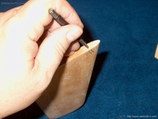
3/16" from the front | |
Make a starting divot in the center of
each Stab | |
Center mark shown in the pic
| |
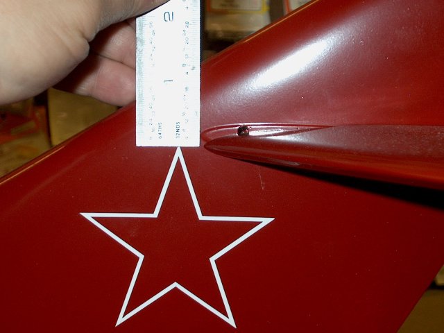
Mark the same distance, in this case 2
3/16", from the front tip of the stab molding on the vertical
fin | |
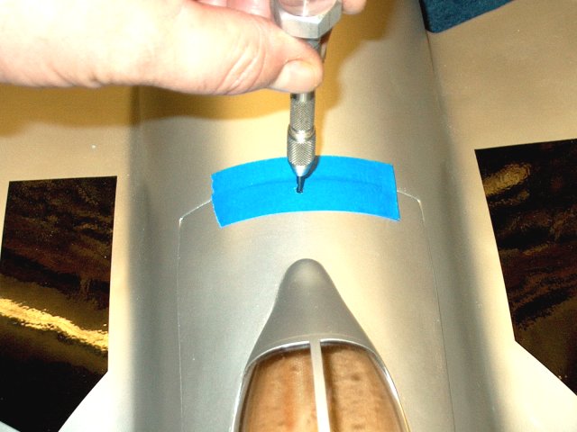
Make a vertical center mark
| |
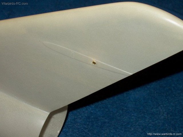
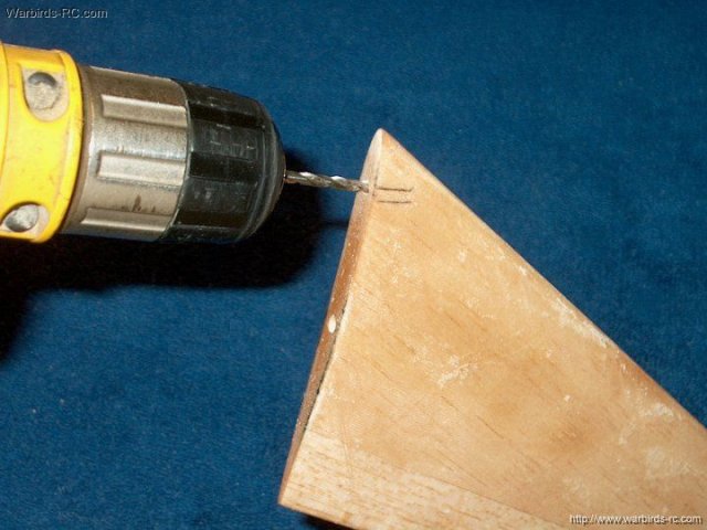
Take great care and drill dead center on
the mark | |
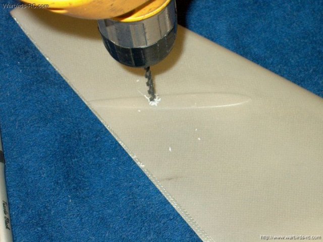
The hole is opened up with a 5/32" drill
bit | |
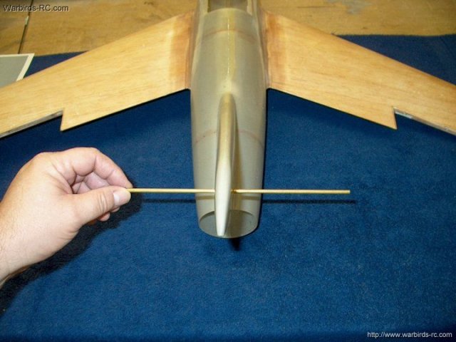
Install a piece of 5/32" OD brass tube
through both holes and check alignment. If it is off, you may
have to file the holes so both sides are the same
| |
Seal one side of the two remaining 1/8" x
1/2" ply squares with CA | |
Mark punch holes in the pieces at the
center for drilling | |
Drill a 5/32" hole in each of the two ply
squares | |
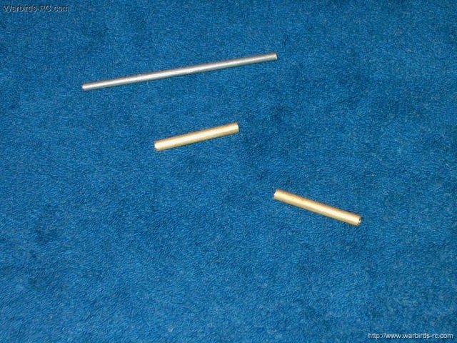
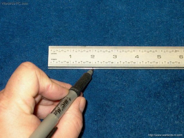
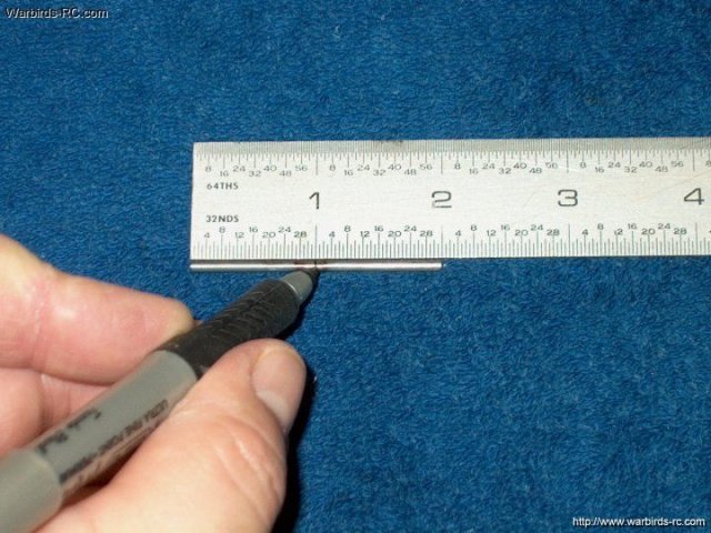
A piece of 1/8" wire is marked and cut to
3" long | |
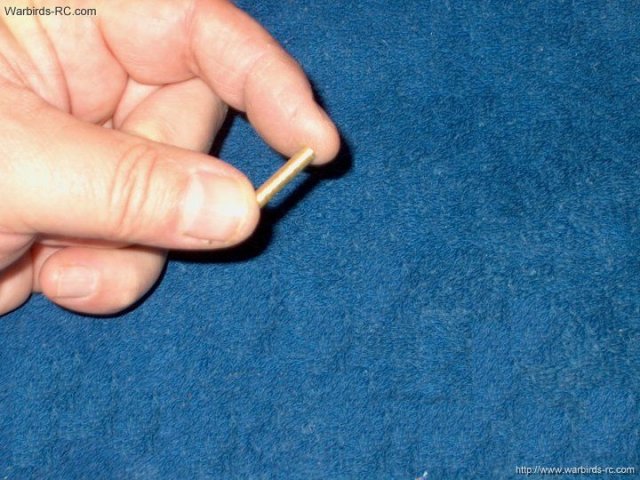
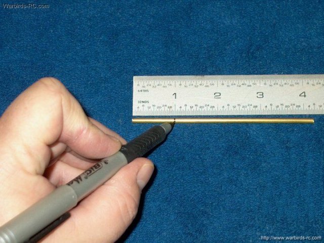
Two pieces of 5/32" brass tube are marked
and cut to 1 1/4" long | |
The brass tube is inserted into the
vertical fin area and marked to cut so it will remain flush to
the sides of the fin. The two ply plates are positioned and
checked for center, then tacked in place with epoxy
| |
The piece for the fin is cut to
length | |
The brass tube is installed and checked to
make sure it is flush on each side. Sand as necessary for a
good fit | |
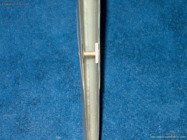
Photo shows the brass tube and plates in
place | |
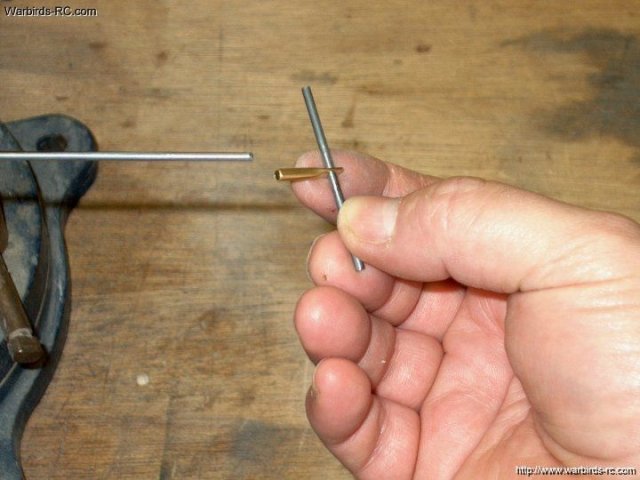
The two 1 1/4" brass tubes should be
roughed up on the outside with sandpaper before gluing in
place | |
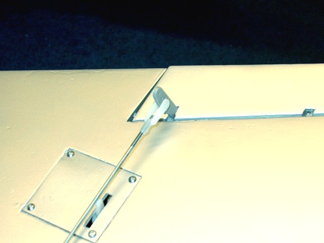
The 1/8" rod and tubes are test fit for
free movement | |
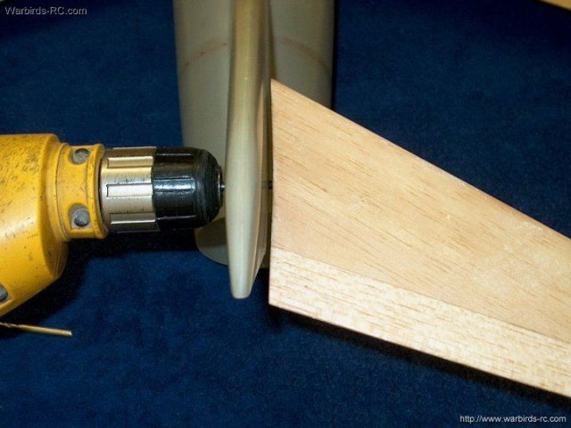
A drill is run through the center of the
fin, drilling the pivot hole in the stab. Hold the stab flush
to the side of the fin and perpendicular to the fin while
drilling | |
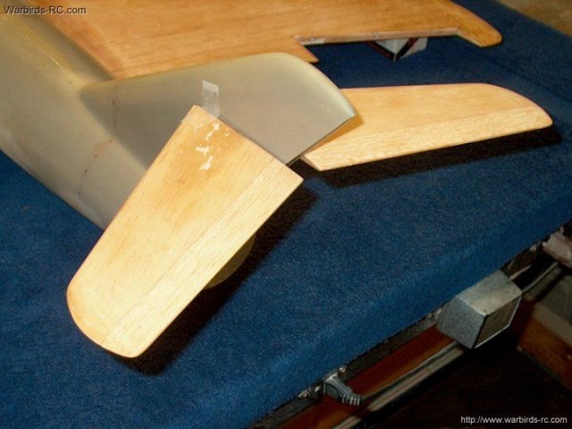
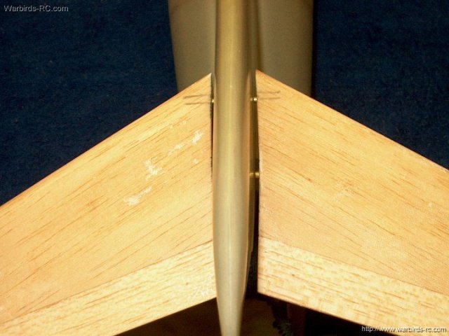
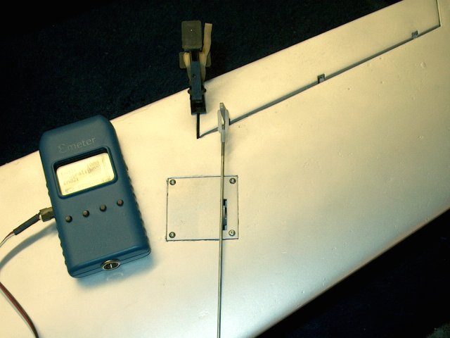
The Horizontal Stabs are test fit and
position is checked | |
Check position of the Stabs from the rear
to make sure they are parallel to the wings and perpendicular
to the tail | |
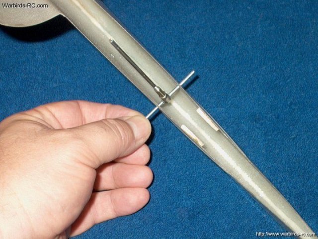
With the 1/8" wire installed, make a mark
1 5/8" from the front of the wire forward to mark the front
position for the actuator wire | |
Measure and make a mark 1/8" back from the
front line you made for the area that needs cut
| |
Use a sharp knife or cutting tool to open
the area, then fin shape it with a file or small router
bit | |
The slotted area is shown shaped and ready
for installation | |
A piece of 1/8" brass tube is used for the
actuator assembly and should appear squared up to the sides of
the vertical fin as shown | |
Mark and cut a piece of 3/32" wire (4-40
push rod) to 2" in length | |
This pushrod is used as the actuator for
the Elevator | |
A piece of 1/8" brass tube is marked and
cut to a length of 1" long. Make two of these tubes
| |
The 3/32" rod and two 1/8" diameter brass
rods are ready to install | |
Slide the brass tubes over each end and
install the assembly through the slots. Holding the rod
against the front on both sides so it is kept straight, mark
on the front part of each Stab to indicate their
position | |
Make a center mark on each Stab
| |
Use a punch to start a hole. Keep it
centered on the airfoil and between the two fin marks you made
when the rod was installed | |
Use a 1/8" drill to bore the holes for the
brass tubes. Keep it centered and at the same angle as your
two lines and be careful to not overdrill
| |
Both Stabs have been drilled and the brass
tubes installed. Check the front and rear of the Stabs to make
sure they are even with eachother. If one side is lower than
the other, you may have to enlarge one hole to lower the brass
tube | |
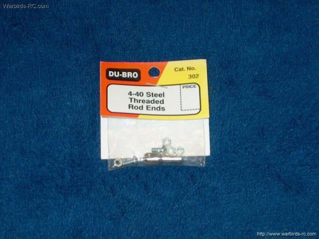
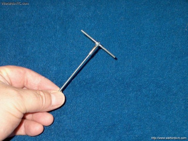
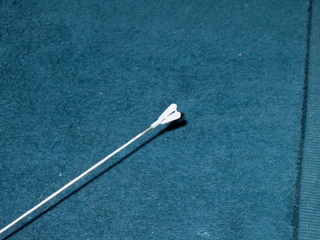
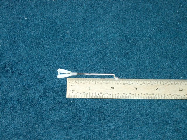
A "T-Bar" Elevator Control Rod will need
to be made using the 2" rod you cut. There are two methods of
doing this and both are included with this construction
manual. The first and prefered method is to use a 4-40
threaded rod end for the "T" as shown below
| |
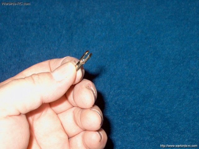
Shown is a closeup of the heavy duty rod
clevis. One side is open for a bolt to pass while the other
side is threaded | |
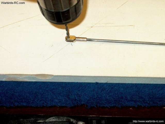
Install a 4-40 threaded push rod on the
clevis to help hold it and drill the threaded clevis arm with
a 3/32" bit so the rod will fit | |
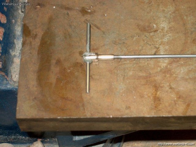
The 3/32" x 2" rod and clevis are dipped
in soldering flux, then the rod is inserted and centered in
the clevis | |
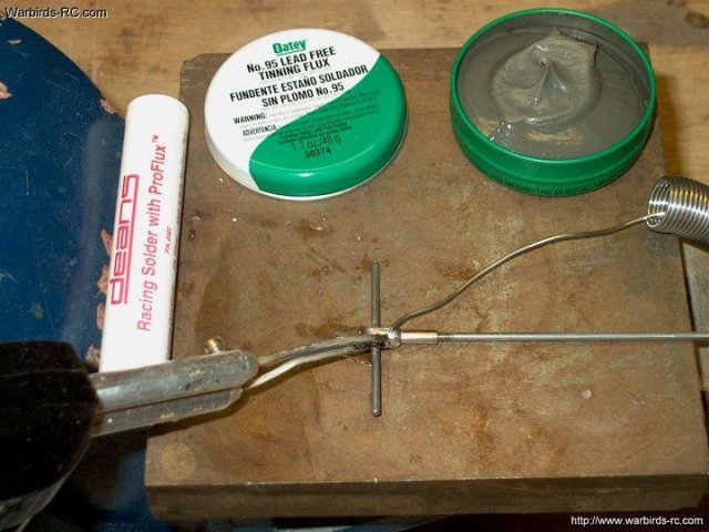
Use a high quality silver solder for the
job and fill the area with solder between the two clevis arms.
Make sure the "T" is squared and perpendicular to the control
rod | |

Clean up the assembly with a micro wire
wheel and check for a strong joint. This is the prefered
method of making a T-Bar as it is adjustable using the 4-40
threaded rod | |
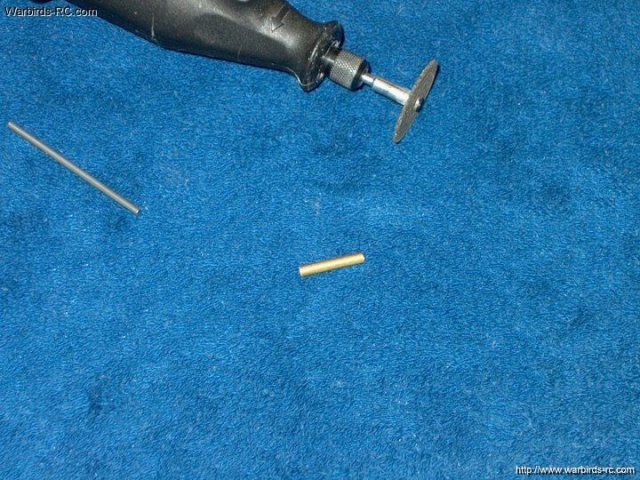
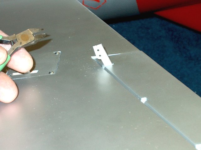
If you do not have a pushrod assembly, you
can use a piece of 1/8" brass tubing instead. Cut a piece to
3/4" in length | |
Flatten the first 1/4" of the tubing using
pliers | |
Using a 3/32" drill, make a hole in the
center of the flattened area | |
A center line is marked on the control
rod | |
The control rod is inserted through the
hole while the rest of the brass tube is slipped over a 4-40
rod. Make sure the brass and rods are clean and add soldering
flux before installing | |
The assembly is soldered at the T and the
pushrod joints. Be sure to keep the control rod perpendicular
to the pushrod | |
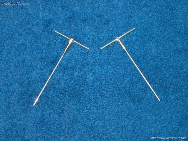
The T-Bar on the left only weighs one more
gram than the one on the right and is adjustable. However, the
one on the right is simpler and cheaper to make, so it's your
choice. The key to success is to use a good solder and flux,
otherwise you will never get the joint strong
| |
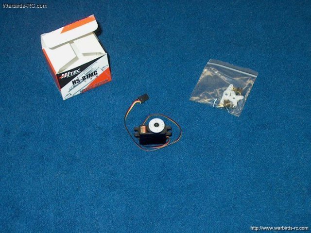
The servo for the Elevator should be metal
gear, as others have been known to strip in as few as a couple
flights. | |
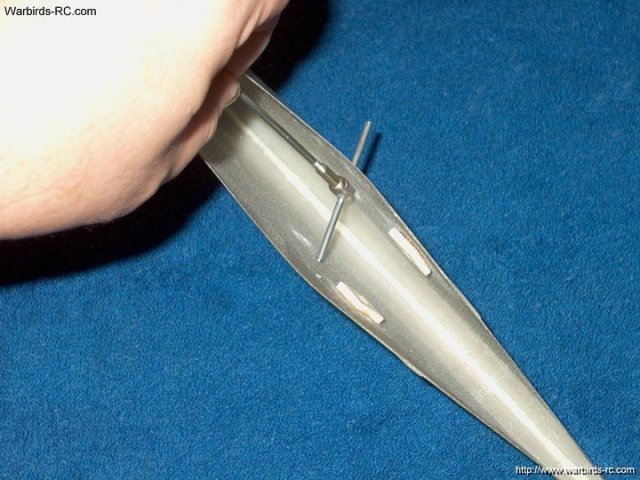
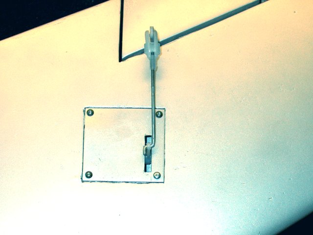
One end of the "T" Rod is inserted into
the slot, then the center is spread so the other side will fit
into it's slot | |
Control shown in place
| |
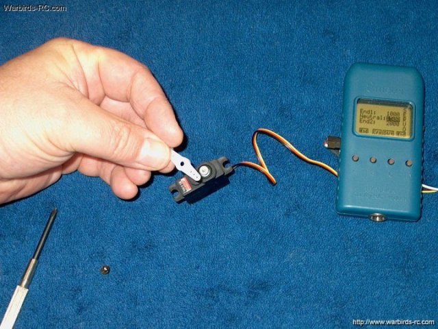
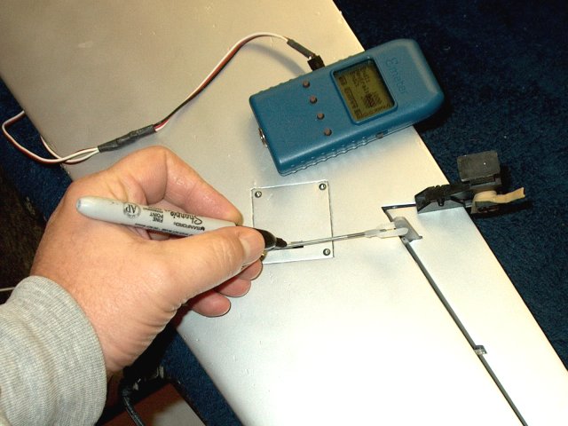
The Elevator servo is centered with the
receiver or a servo tester | |
Trim off one side of the servo horn
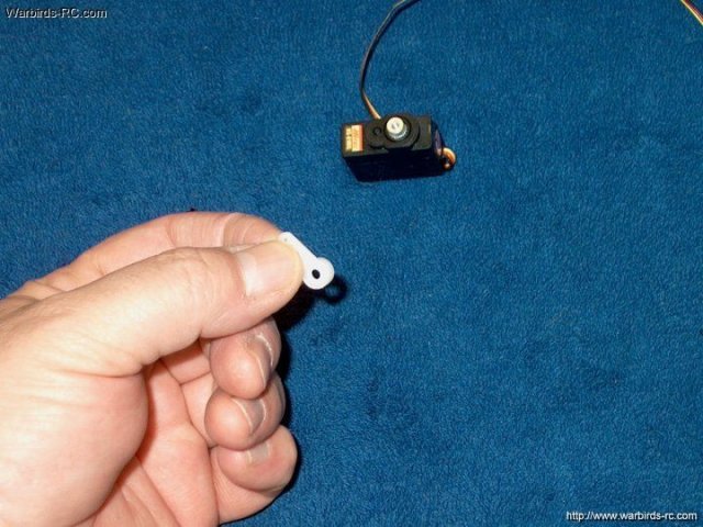
| |
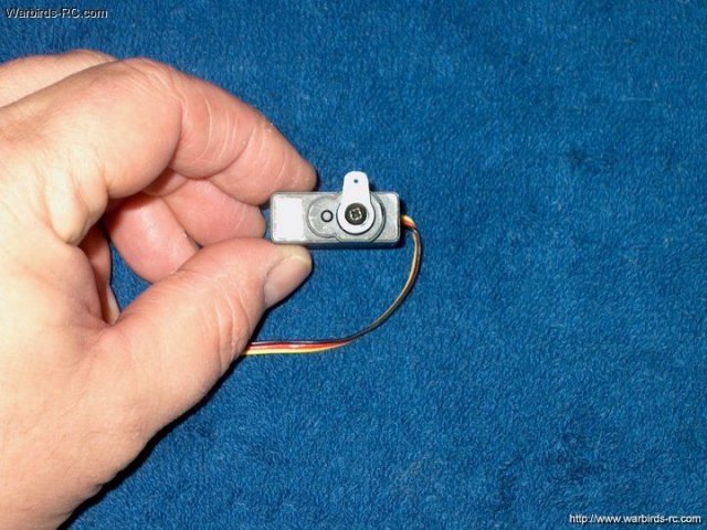
The other side of the horn is shortened to
the first hole, then installed on the servo
| |
The servo area is cleaned with Denatured
alcohol | |
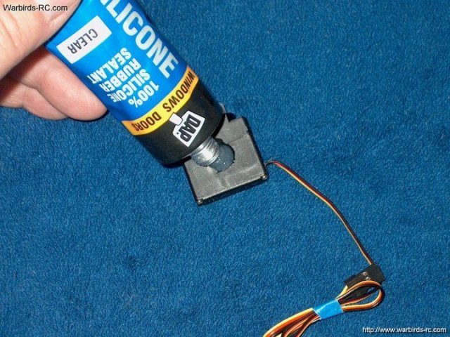
Silicone rubber is applied evenly to one
side of the servo | |
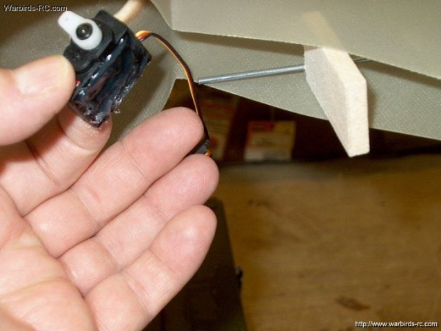
A piece of wood keeps the vertical spread
apart so the servo can be placed in its location and the
control rod is used to align and square up the servo
| |
Install the servo to one side of the
fuselage as shown | |
Tape up one of the holes for the flying
stab main shaft | |
Install the brass tube for the
shaft | |
Use thick CA to glue one side of the tube
to the inside ply plate | |
Glue the other side of the tube with thick
CA | |
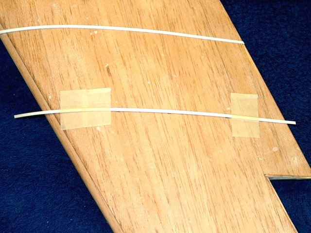
Find the 1/8" x 3/16" balsa strip that is
about 18" long. Cut the strip into two pieces
| |
Make a mark inside the fuselage about 5/8"
from the top of the vertical stab | |
Use tape on the first stick to help hold
it in place | |
Tape the stick flush along the inside edge
of the stab and down to the 5/8" mark. Pivot the stick and
apply thick CA along its length | |
Clamp the stick in place, flush with the
end of the stab until the glue sets
| |
Remove the excess balsa from the end of
the stick | |
Apply thick CA to the other stick and
install on the other side of the inner stab wall, flush with
the end | |
Clamp the stick in place until the glue
sets | |
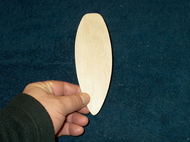
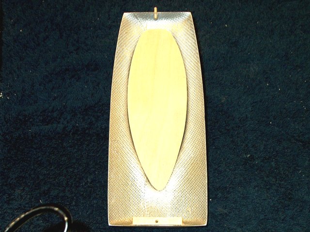
Use a scrap piece of 1/4" thick balsa and
outline the stab top pattern, then cut the piece to fit
| |
Apply some thick CA to the area as
shown | |
Install the balsa filler piece in the top
of the stab | |
Lightly sand the rear of the stab to
remove any exposed balsa, but do not sand into the
fiberglass | |
Mark the inside center of the
rudder | |
Mark the center rear of the rudder
| |
Draw a vertical line down the middle of
the ruddder end | |
Apply several strips of masking tape to
the rear of the vertical stab | |
Using thick CA, apply a bead down both
wood stab spars | |
Position the rudder in place, making sure
it is centered at both the top and bottom
| |
Use the masking tape to hold the rudder in
place while the glue dries | |
Rudder installation completed
| |
Use a surface saw to cut away the larger
portion of balsa. Be careful to not cut too much
| |
Apply masking tape to the fiberglass stab
so you don't sand into it and the use a 100 grit block for the
basic shaping | |
Use a saw to cut down the other side of
the rudder | |

Tape should be used so the fiberglass
surface doesn't get marred. Shape the other side of the
rudder | |
Remove the tape and blend the rudder even
with the stab | |
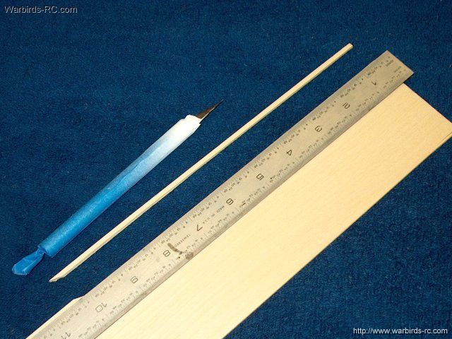
Cut a 3/32" thick strip of basswood to 10"
long | |
Use thick CA and cap the trailing edge of
the rudder with the basswood | |
Cap shown in place
| |
Remove the excess spar from both the top
and bottom | |
Use a fine sanding block to shape the
trailing edge of the rudder | |
Wipe the rudder down with a tac cloth to
prepare it for fiberglassing. Rudder shaping shown
completed | |
Cuta piece of 1/2oz glass cloth long
enough to wrap around the fin | |
Tape off the Stab as shown to catch excess
epoxy | |
Use thick CA to anchor the cloth at the
trailing edge of the rudder | |
Smooth out the CA evenly and allow it to
dry | |
Apply a small ammount of epoxy at the
cloth seam on both sides | |
Use a brush to apply epoxy to the cloth.
Glass both sides | |
Use a spreader to remove excess epoxy from
the sides of the rudder | |
Apply a sheet of plasic to the rudder with
the spreader, removing excess epoxy. Clean up the tape with
alcohol | |
Once the epoxy sets, make a light cut only
through the glass cloth at the point where tape begins. Remove
the tape from the stab | |
Sand and blend the glassed rudder to the
stab, making sure not to oversand. Fine sand with 400
grit | |
Rudder and Stab fiberglassing shown
completed | |
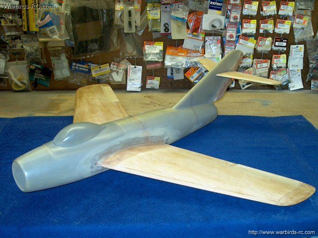
Mig-15 basic airframe assembly completed
and ready for paint | |
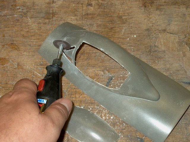
Carefully rough cut the canopy frame
outside the marked lines to remove the window area
| |
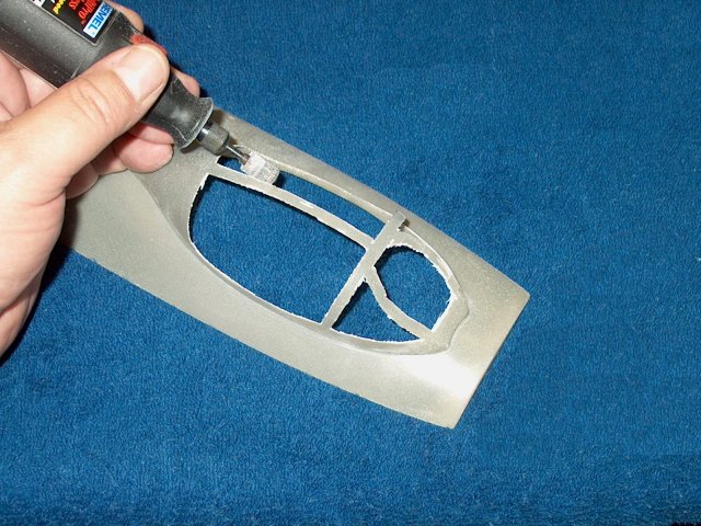
Use a sanding drum to shape each
rail | |
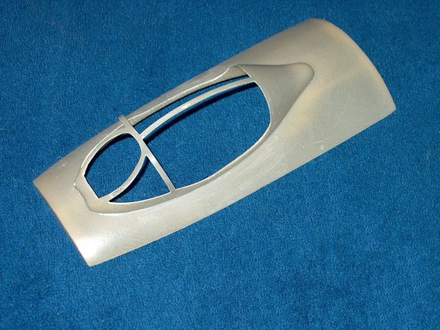
Fine sand the canopy to a finish as
shown | |
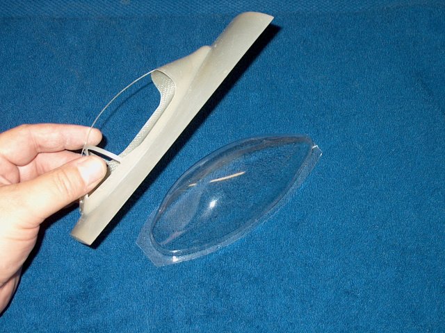
Install the fiberglass frame over the
clear canopy | |
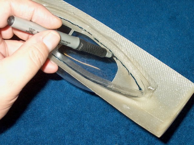
While holding the canopy against the frma,
mark the bottom edge of the clear canopy for cutting
| |
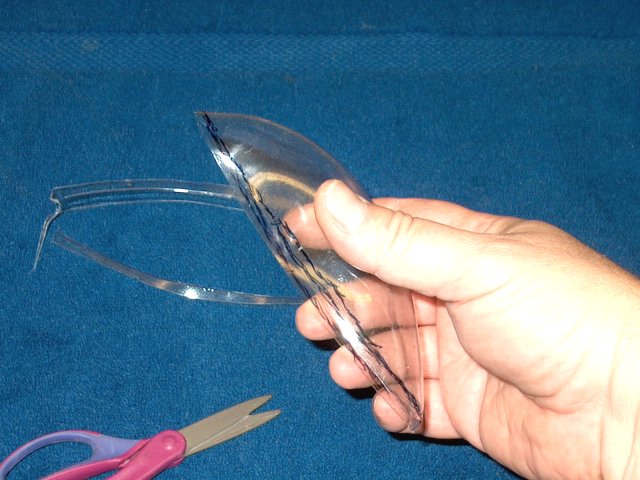
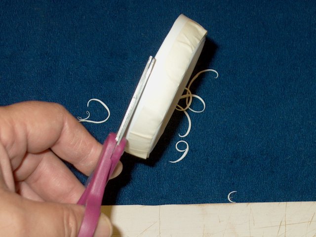
Use a pair of scissors to trim the
canopy | |
Test fit and recut if necessary, but do
not remove too much of the canopy | |
Use alcohol to clean the canopy
marks | |
Fine sand the canopy edges
| |
Cockpit frmae and canopy completed
| |
Position the cockpit frame so it is
centered and flush with the front of the fuselage and tape it
in place | |
Use a 1/8" drill from the front to drill a
dowel hole throght the frame and fudelage
| |
Round the tip of the 1/8" dowel included
in the kit | |
Install the pin with the round side out to
help is slide easier into the fuselage
| |
Use thick CA to glue the dowel in
place | |
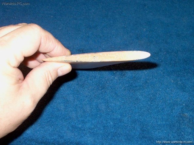
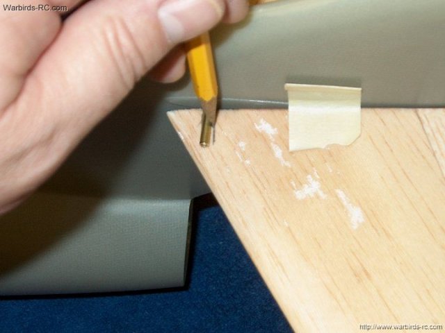
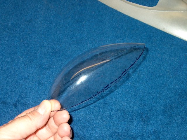
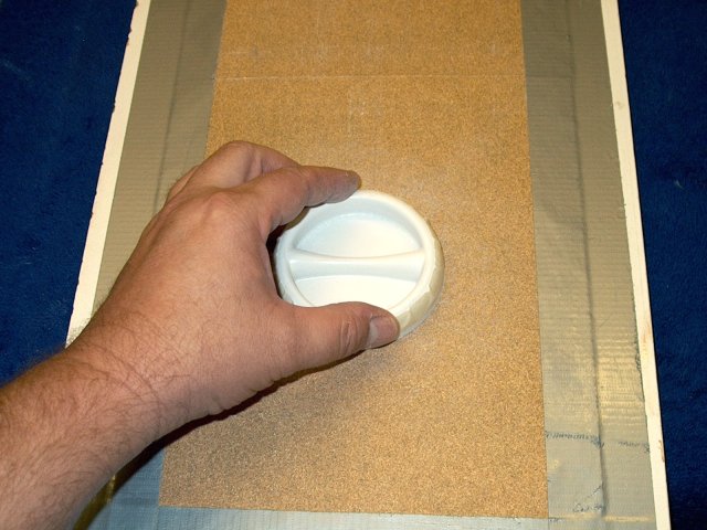
Carefully cut out the intake
| |
Use 1/2" masking tape and apply around the
circumference of the plastic intake
| |
Cut along the tape edge for an even cut
all the way around the intake | |
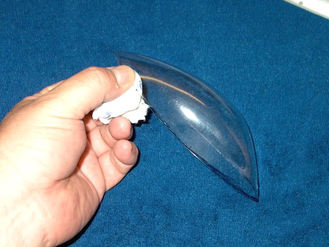
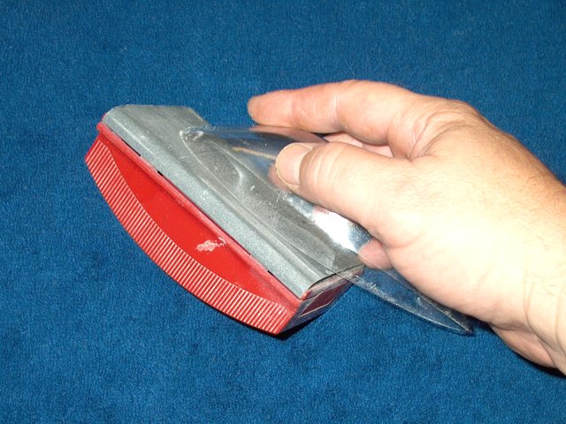
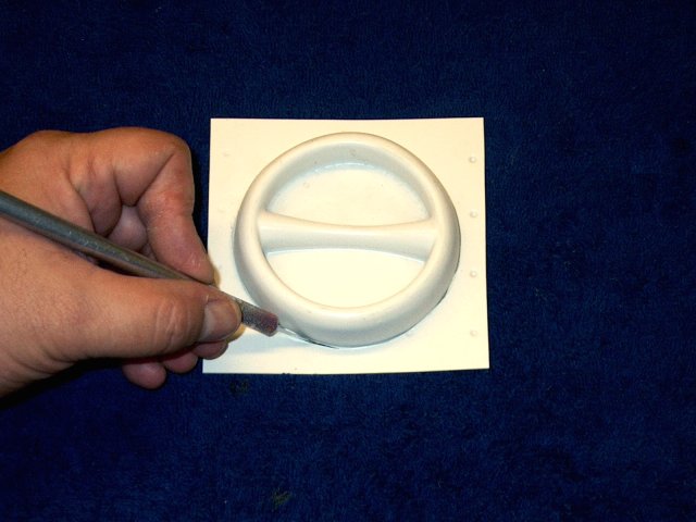
Sand the bottom on a flat surface
| |
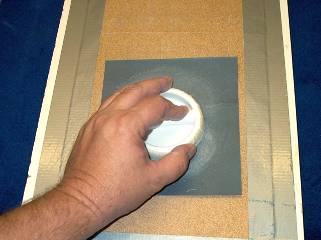
Sand with finer sandpaper to a good
finish | |
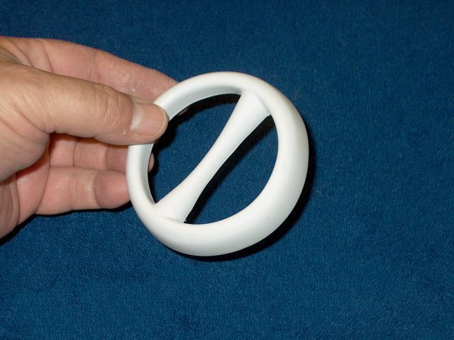
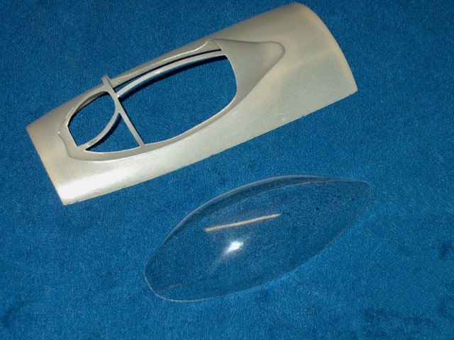
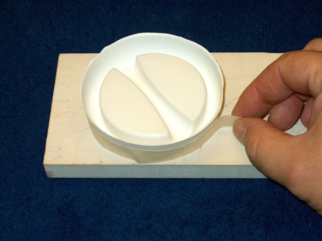
Cut the center evenly, leaving a finished
intake as shown | |
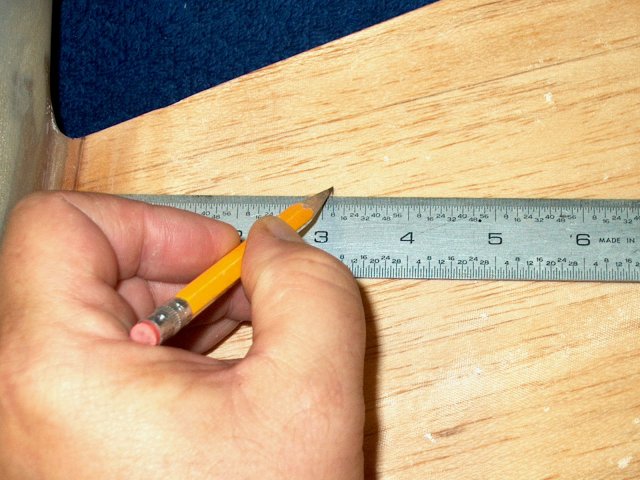
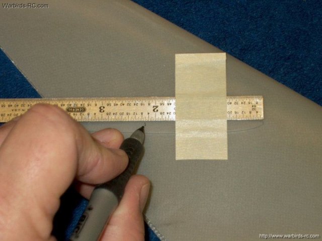
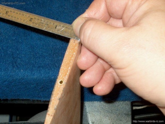
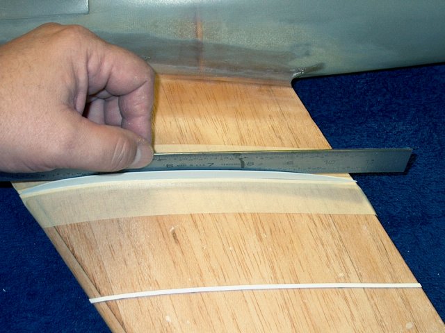
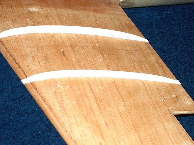
Measure 3 1/8" from the wing seam on the
fuselage. Make several marks along the length of the
wing | |
Trim the patterns for the wing fences from
the paper | |
Cut eight 3/32" strips from one of the
pieces of plastic fence material | |
Transfer the fence patterns to the
remaining four plastic sheets | |
Cut out each fence as shown
| |
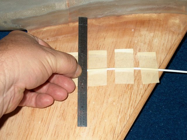
Place a strip with its outside along the
pencil marks at 3 1/8" from the fuselage seam
| |
Use masking tape in the rear so it does
not shift backward, then tape the strip in place
| |
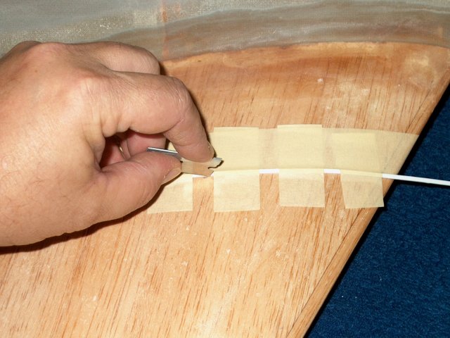
flip the strip over and apply epoxy with a
toothpick along the strip | |
Flip the strip back over and press it down
to squeeze out excess epoxy, which is cleaned up with
alcohol | |
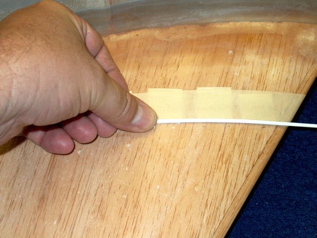
Tape the strip in place until the glue
sets | |
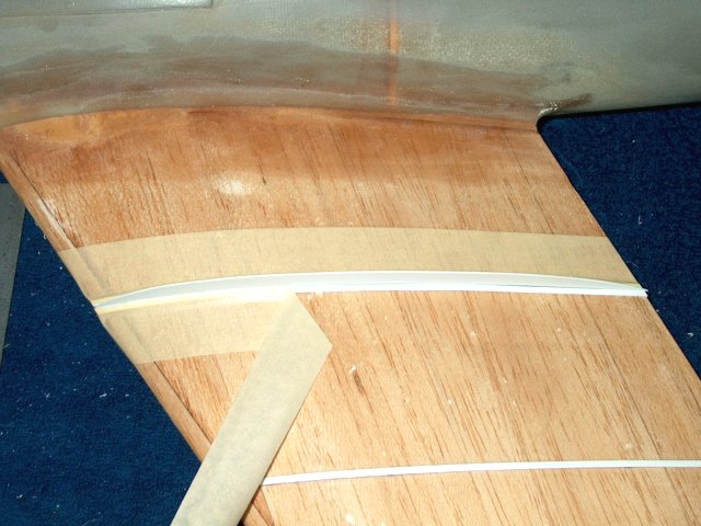
Trim the ends with a razor
| |
Test fit the inside fence
| |
Sand the fence until it is a good fit on
the wing | |
Finish sand the fence, rounding the top of
the fence with fine sandpaper | |
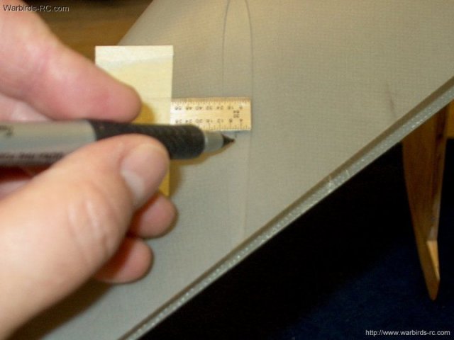
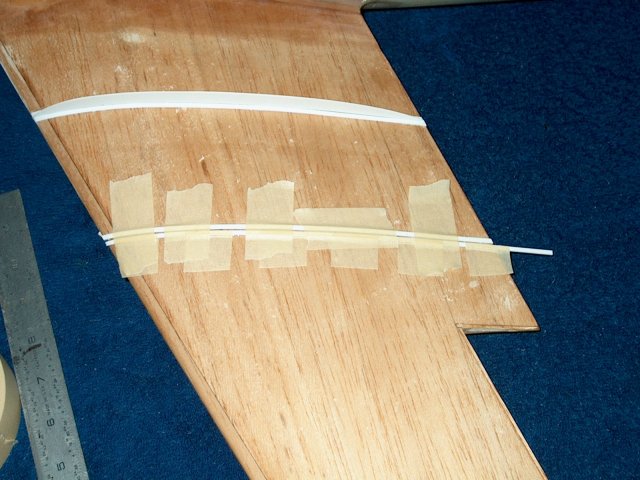
MEasure and make several marks from the
first fence strip 3" past its location
| |
Tape the second strip in place
| |
Trim the excess tape flush to the outside
of the strip | |
Sand the inside of the strip to rough it
up | |
Apply epoxy to the strip
| |
Flip the strip over, then clean excess
epoxy and tape in place. Make sure it remains straight with a
ruler | |
Trim the ends flush
| |
A ruler can be used to scrape away the
excess soft epoxy before it completely hardens
| |
Tape the second strip in place, using a
fence for proper spacing | |
Tape the fence in place and trim the tape
flush to the inside of the slot | |
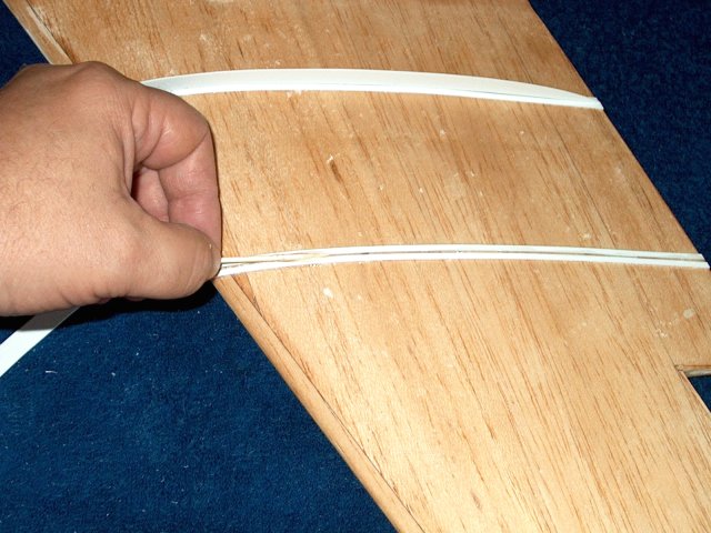
Test fit the fence
| |
Flip the strip over while it is still
taped and rough it up | |
Apply epoxy to the strip
| |
Flip the strip over and press down. clean
the puside with alcohol and the excess epoxy from the inside
using a left over piece of fence material
| |
Tape the strip in place until the glue
sets | |
Remove the tape
| |
Check again the inside slot and clean if
necessary | |
Apply glue along the slot as shown. Remove
any spill over wiht alcohol and a paper towel
| |
Install the fence
| |
Check it with a ruler for straightness.
Make sure it is perpendicular to the wing surface
| |
Let the glue set, then remove all
tape | |
PRepare the second outside fence strip as
shown | |
Rough it up, then apply glue along the
strip, then flip it over and clean up
| |
Install the second shorter fence the same
as the first | |
Measure the second wing 3 1/8" from the
fuselage joint | |
Tape a strip in place with the marks on
the outside | |
Trim the tape flush to the outside. Glue
the strip in place like the first side
| |
Glue the second strip to the fuselage,
making sure it remains straight and tape it in position
| |
Trim the ends | |
Trim the front | |
Clean up any excess soft epoxy
| |
Apply epoxy to the slot
| |
Clean up excess epoxy
| |
Install the larger fence, maaking sure it
remains straight and perpendiculaer
| |
Measure 3" from the fence
| |
Tape a strip on the inside of the
marks | |
Cut the tape flush as shown
| |
Flip the strip up, rough it with sandpaper
and apply epoxy | |
Flip it over and clean up excess, then
pate it in place until the epoxy sets
| |
Check for straightness, then install the
second strip and last fence as previously described
| |
Fence installation shown completed
| |
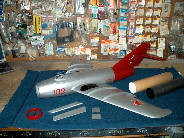
Paint your model before final assembly.
The model chosen in the photo was the "Red Tail" MIG-15
| |
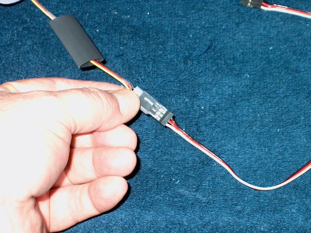
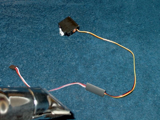
Install a 12" servo extender wire on the
Elevator sevo lead and use heatshrink to retain it. Run the
lead forward into the cockpit area | |
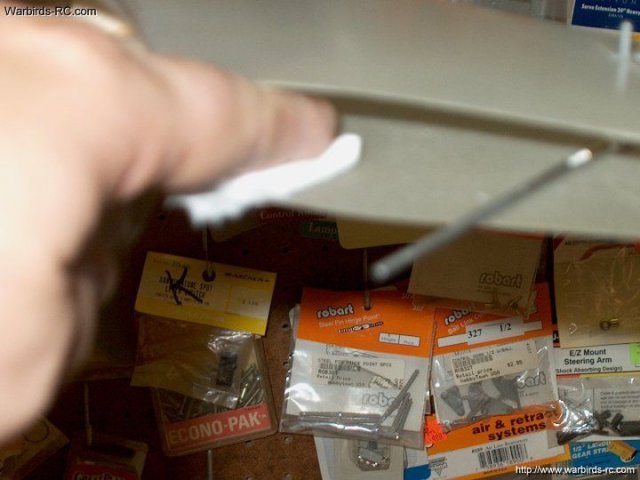
Install the fiberglass thrust tube in the
model from the rear. Make sure the Elevator servo lead runs
through the top of the center former and the tube engages the
center former | |
Push away the rear of the thrust tube into
the fuselage and run a bead of clear silicon sealer around the
edge. Wipe away the excess, push the thrust tube rearward,
flush with the end of the fuselage and allow the sealer to
dry | |
Run a bead of medium CA about 1/4" away
from the exit. Install the thrust ring 1/4" away from the
end | |
Use your finger to make a fillet of CA
against the back of the thrust ring
| |
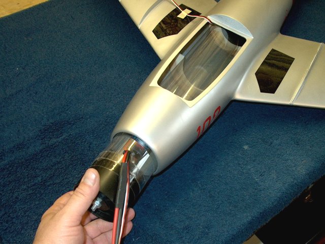
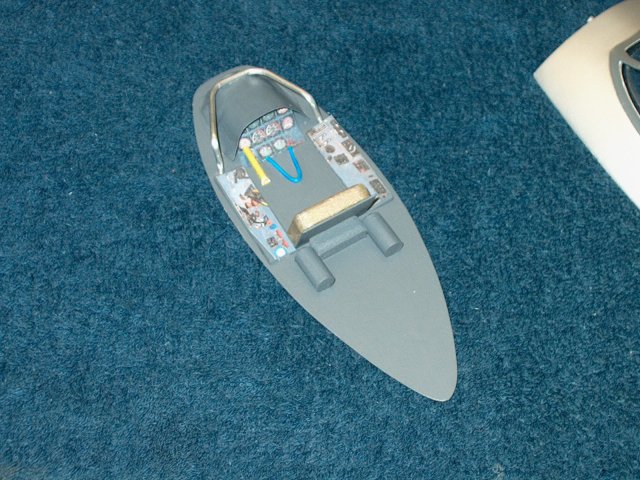
Install the fan assembly and clear thrust
tube from the front of the fuselage
| |
Press and seat the fan in the rear outer
fiberglass thrust tube. It should be a tight fit
| |
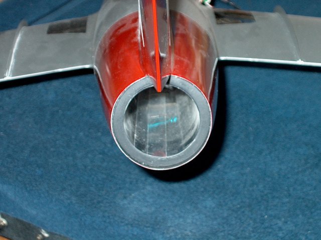
The clear thrust tube should be centered
in the rear thrust ring as shown | |
If necessary, install 6" extender wires on
each Aileron servo. It was not necessary for the Hitec
HS-81's | |
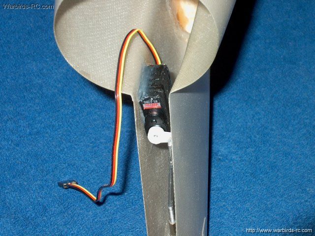
Use a thin strip of Carbon Fiber to pull
the Aileron lead through the wing and into the fuselage
compartment. Use servo tape on the back of the servo and
install each servo in the wings | |
Cut a 3/16" wide slot in each servo door
for the horn to exit | |
Remove the balsa from the servo area of
each door so the door sits flush | |
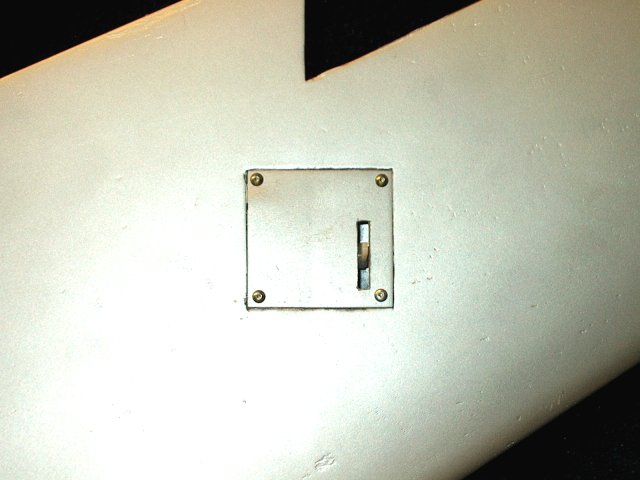
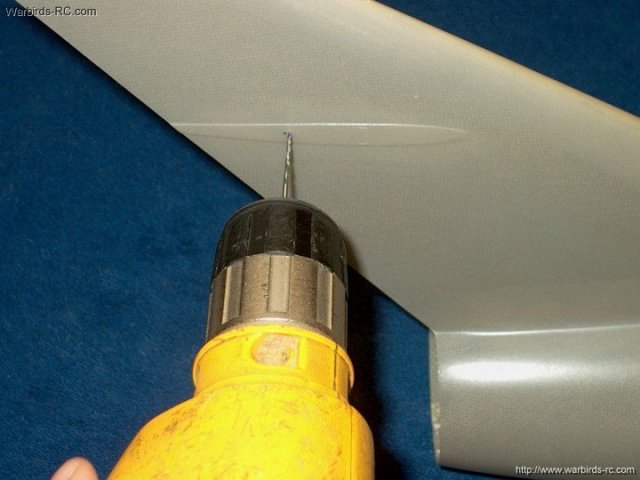
Drill 1/16" holes 1/8" away from each
corner of the doors and into the wing mounts, then open up the
holes in each door so #2 button head screws will slip through.
Install the doors with #2 x 3/8" button head screws
| |
Connect an Aileron "Y" adapter to the
servo leads and use heatshrink to retain them
| |
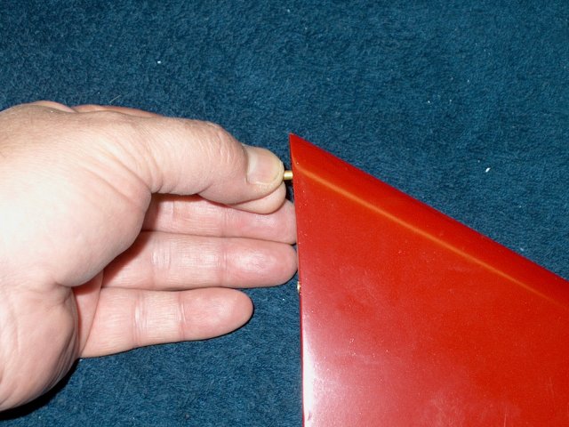
Prepare each Robart Pin Hinge by
installing a piece of thin plastic over the hinges as
shown | |
Apply epoxy to the hinge holes in the
Ailerons with a toothpick | |
Install each hinge so they are seated
fully and pivot correctly. Clean up any excess and make sure
the hinges pivot without binding. Remove the plastic once the
epoxy sets | |
Install frsh plastic on each pin hinge.
Apply eposy to the wing holes and install the Ailerons. Clean
up excess epoxy and remove the plastic once the glue
sets | |
Install a clevis on each of two 2-56
pushrods | |
Clip the clevis in the second hole from
the Aileron | |
Use a receiver or servo tester to center
the servo | |
Clamp the Aileron in a neutral position
and mark the rod at the servo horn outer hole location
| |
Make a Z-bend at the marked location as
shown | |

Drill the servo horn outer hole with a
5/64" bit so the wire will fit | |
Trim the Aileron horn as shown, then sand
and shape, rounding the ends | |
Install the pushrod assembly and adjust
the clevis as needed | |
Repeat the procedure and install the
pushrod for the second Aileron | |
Cut a piece of 1/4" thick ply or two
laminated pieces of 1/8" ply to 1 3/4" x 1 1/4". Drill a hole
5/8" from the front of the plate and cut a recess 3/4" long
for the towhook wire | |
Use a piece of 2-56 wire 3" long and bend
a right angle 3/4" long at one end. Check the fit in the ply,
then apply epoxy and install the wire in the hole
| |
Add a bead of epoxy across the top of the
wire as shown | |
Measure 6" back from the front of the
fuselage and mark a center location
| |
Drill a hole for the towhook wire
| |
install the plate and use a pencil to mark
the area of the towhook plate | |
Install a thick layer of epoxy and
fiberglass mil in the bottom area of the fuselage
| |
Apply epoxy to the bottom of the towhook
plate and install the plate. Remove excess epoxy, allowing for
a fillet around the plate | |
Cover the fuselage with tape so you don't
mar the finish and bend the towhook to shape
| |
The towhook should have a slight down
angle to it | |
Install the intake tube from the front of
the fuselage so that about 1/8" extends past the front. Apply
a bead of Silicon around this joint
| |
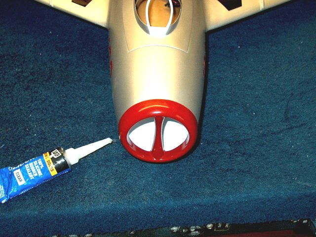
Apply a thick bead of silicon sealer to
the inside edge of the intake nozzle, then install it centered
on the fuselage. Allow the silicon to set overnite
| |
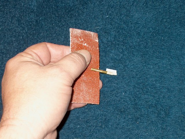
Rough up the small forward brass tubes for
the Elevators with sandpaper, leaving about 3/8" smooth on one
end | |
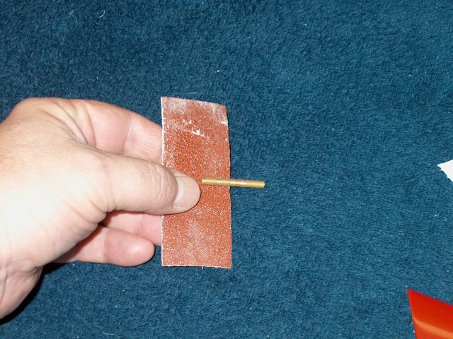
Rough up the larger pivot brass tubes with
sandpaper | |
Apply epoxy to the forward holes and
install the small brass tubes so about 1/4" extends past each
Elevator | |
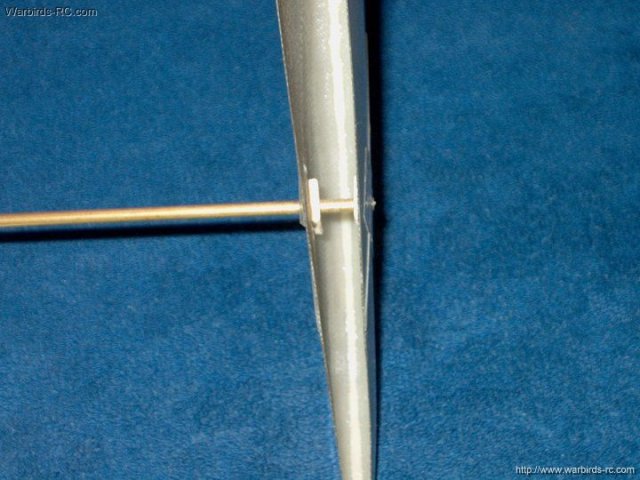
Install the 1/8" pivot rod in the
center | |
Apply epoxy to one Elevator hole and
install the brass tube so about 1/32"-1/16" remains past the
surface to act as a bearing. Install the Elevator and check
for clearance. You want the joint close without binding
| |
Repeat the procedure for the second
Elevator and mount it in place. Tension on the front steering
rods will hold them on and you can remove the Elevators and
put a very slight forward bend in each of the forward rods to
adjust tension | |
Sand the outer edge of the canopy about
1/8" wide with 100 grit sandpaper to rough it up
| |
Apply a bead of RC-56 canopy glue around
the canopy and across the back | |
Install the canopy and let it dry. You can
use some weights to make sure it is seated well in the
frame | |
Cut a piece of 1/4" square hardwood about
1 1/2" long. Drill a small hole down the center
| |
Epoxy the piece in place at the rear of
the canopy as shown, flush with the bottom
| |
Drill an outer hole in the canopy using
the hardwood as a guide | |
Install the canopy, make sure it is
centered, then drill a hole down through the fuselage lip with
a hand drill | |
Open the hole so a #4 hex head screw can
be installed, then mount the canopy on the fuselage and
install the #4 hex head retaining screw. This leaves the
fuselage outside surface smooth and free of screw heads
| |
To build a cockpit, you will need to make
a floor first that will clear the batteries. Cut a piece of
paper to the size of the canopy area. You can hold it up to
the light to rough trace it | |
Transfer the pattern to a piece of 1/32"
ply and cut it from the sheet | |
Sand and shape the floor so it fits in the
recess and sits on the top edges of the canopy
| |
You can build a semi scale cockpit if you
wish from scrap wood | |
A Cockpit adds realism to your model,
however, if you decide on a 3S setup, you may need to paint
the canopy black and leave the cockpit area open for battery
clearance | |
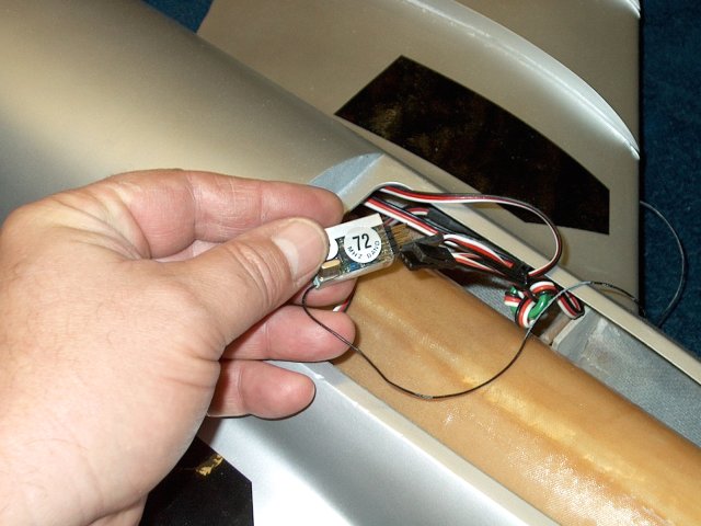
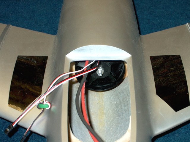
Install a full range receiver and plug in
your Aileron, Elevator and ESC wires. You can tie wrap and
dress them so they are out of the way
| |
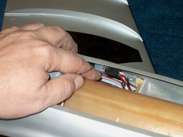
Use servo tape or velcro to attach the
receiver to the side wall of the model as shown. Route your
antenna out the rear or drill a small exit hole in the side of
the fuselage under the wing. Be sure to range test your
antenna location before flying | |
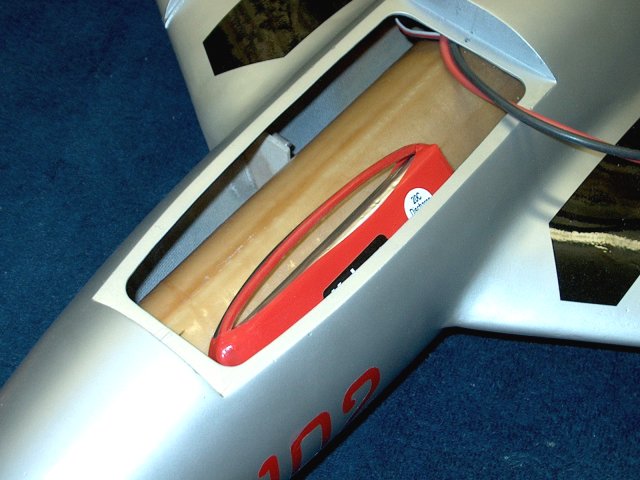
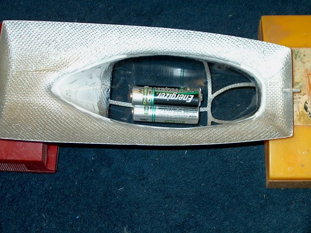
Two 3300 2S 20C Lipos are installed so
they saddle both sides of the forward cockpit area. The
batteries are run in series for a 4S setup
| |
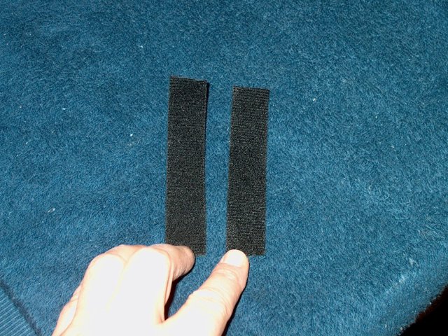
For battery retention, cut two double
sided velcro straps to a length of 4 1/2"
| |
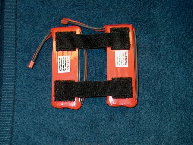
The straps will be installed as shown. You
are viewing the bottom side of the batteries that go face
down | |
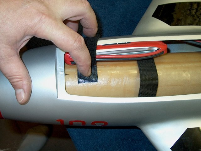
Install a battery and push it forward,
then install a piece of 1" velcro square on the center of the
intake. Fold the strap over to the other side for the second
battery | |
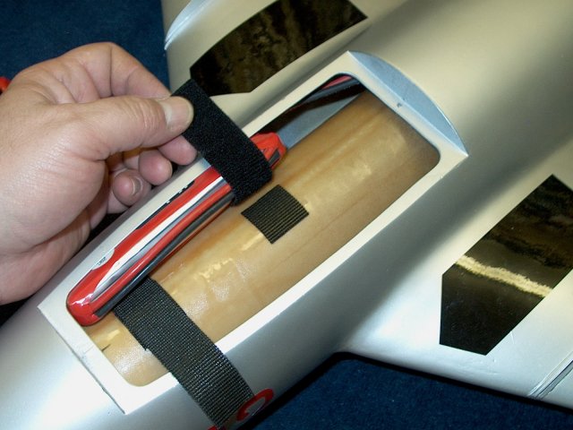
Install a second velcro square under the
rear strap. You could also run a velcro strip down the entire
center top of the intake to allow for adjusting battery
position. The straps will keep the battery pack in its side
slot, while also preventing it from shifting backward during
flight | |
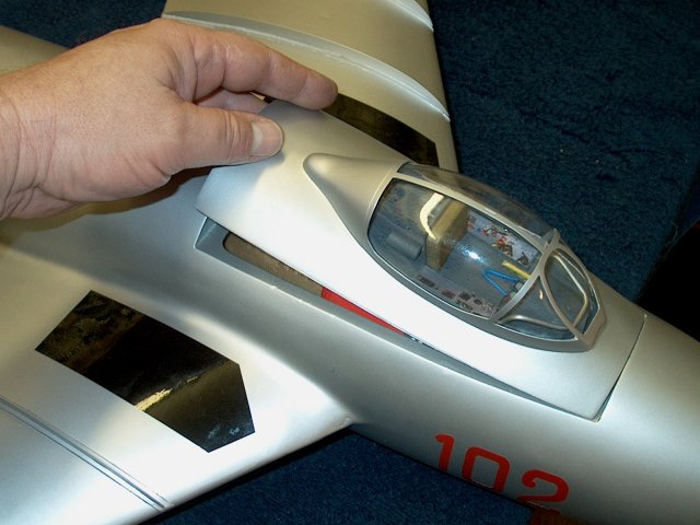
Install the second battery and then the
canopy, making sure the batteries do not bind against the
bottom of the canopy. With the batteries shown or similar
ones, this will not be a problem | |
Make a mark for the CG location on each
wing at 3 5/8" from the rear root. Adjust your battery
position so the plane balances at CG
| |
Set Aileron throws at 1/8" up and 3/16"
down for initial settings, then add more throw if desired
after your first flight | |
Set Elevator throw at 3/16" up and down
for the first flight, then add more if necessary | |
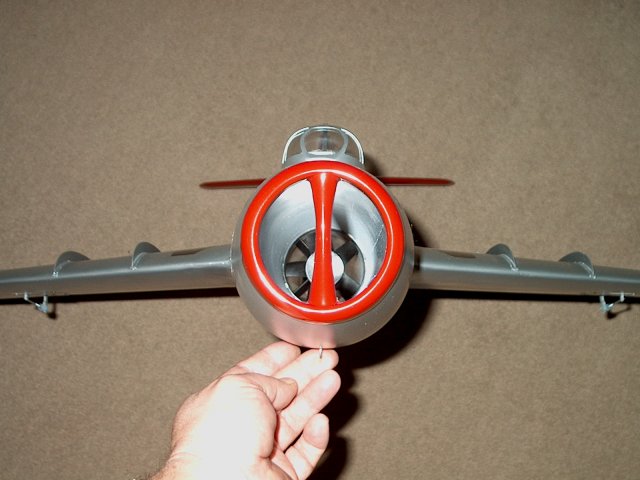
Front view of the intake shows a clean and simple design
| |
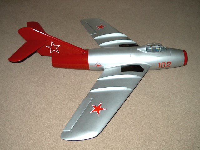
Right side view of the MIG-15
| |
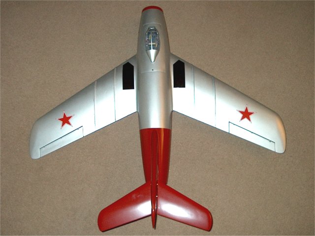
Top view of the MIG-15
| |
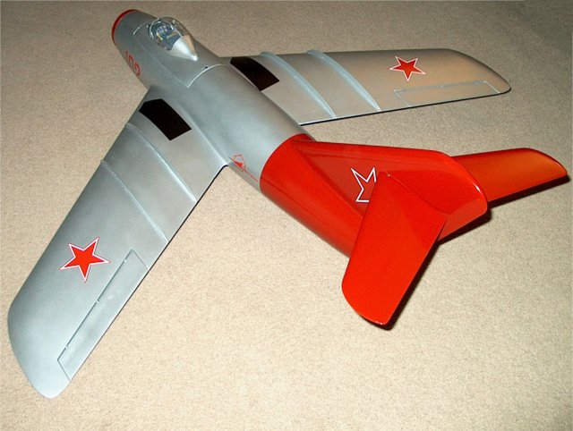
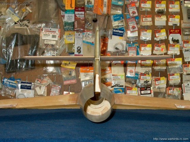
Rear view of the MIG-15
| |
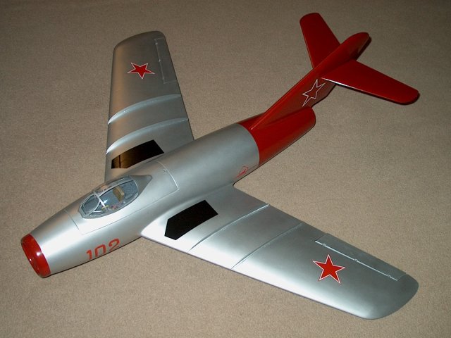
The K&A MIG-15 Fagot EDF Jet
| |

This Website and all documents herin are Copyright © 2012 www.scalerocketry.com -
All rights reserved.
| | | |