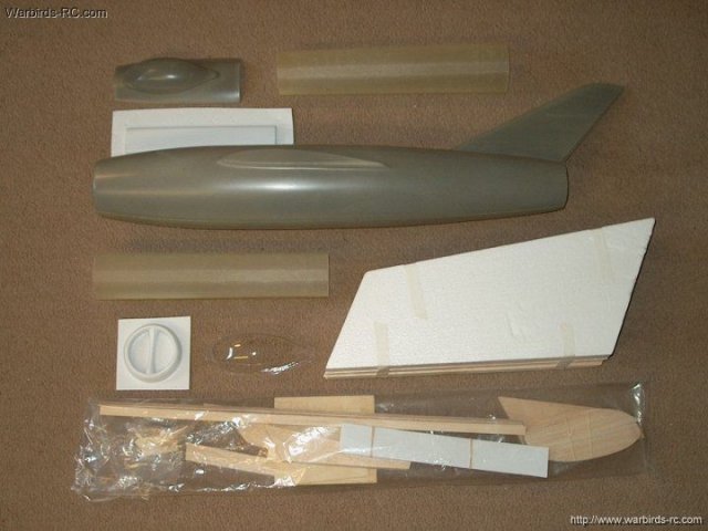
01 - K&A Models MIG-15 EDF as it comes
from Markos at Warbirds-RC | |
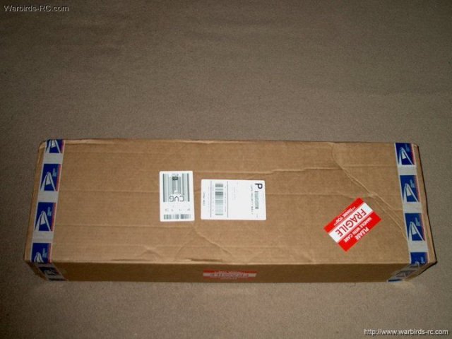
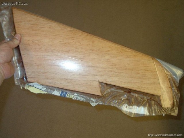
02 - The MIG was well packed from the
maufacturer and Warbirds-RC. It comes in two versions, the
Basic version or the Deluxe Pre-Primed version with
Pre-sheeted wings, clear canopy and more for a small
additional charge. The Deluxe version is shown below and worth
it | |
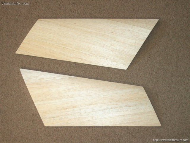
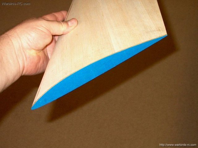
03 - Pre-Sheeted wings come with the
Deluxe Pre-Primed Kit and are well worth the few extra
dollars | |
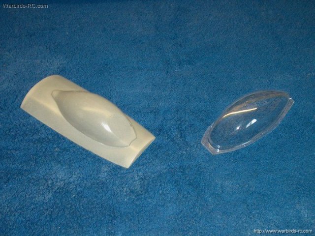
04 - You also get a clear canopy with the
Primed kit | |
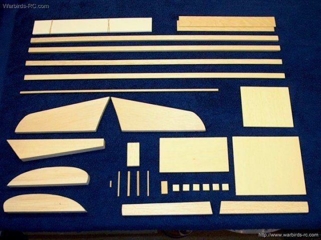
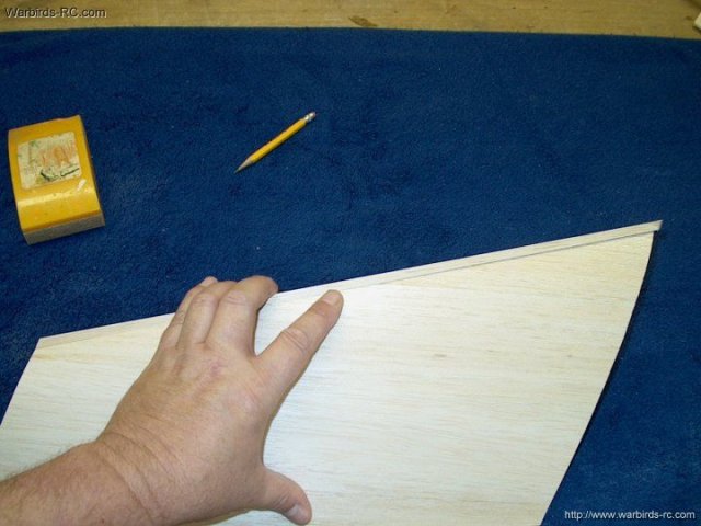
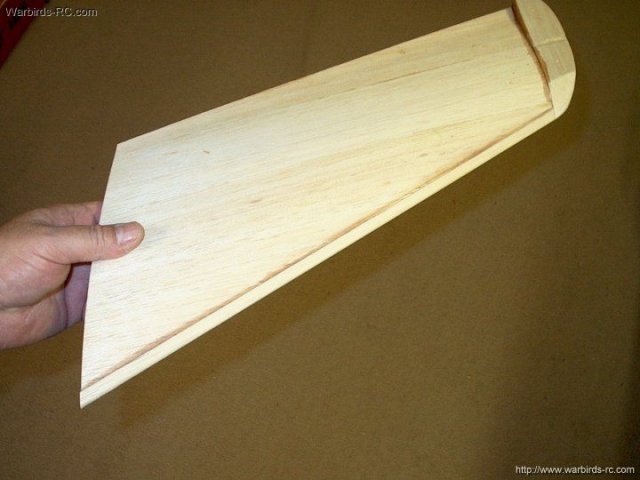
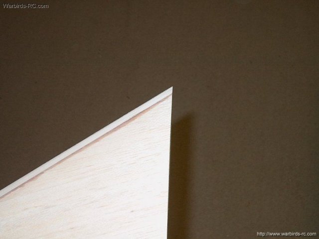
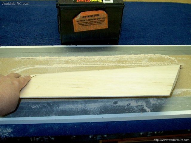
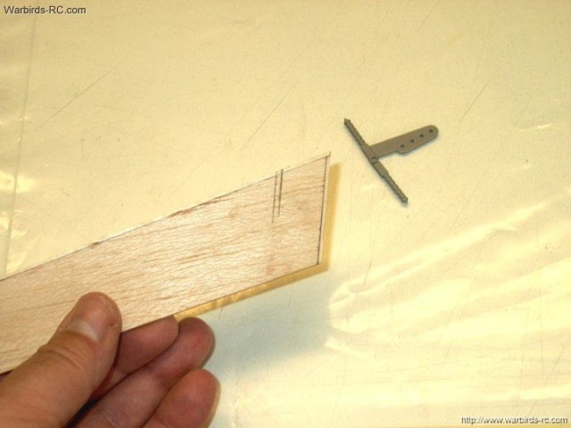
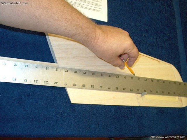
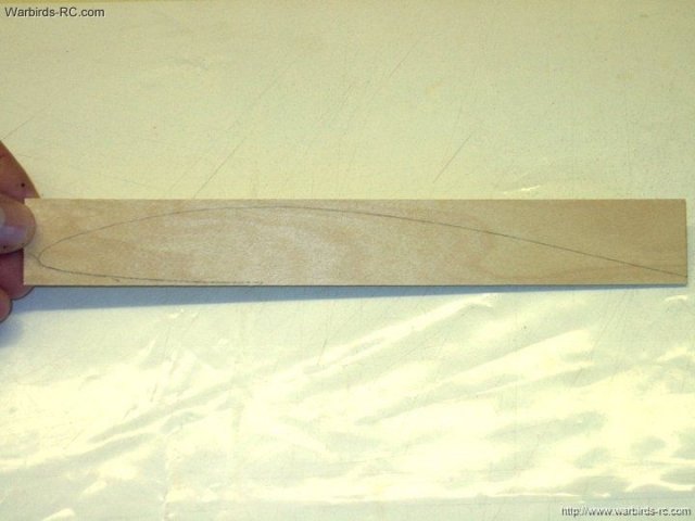
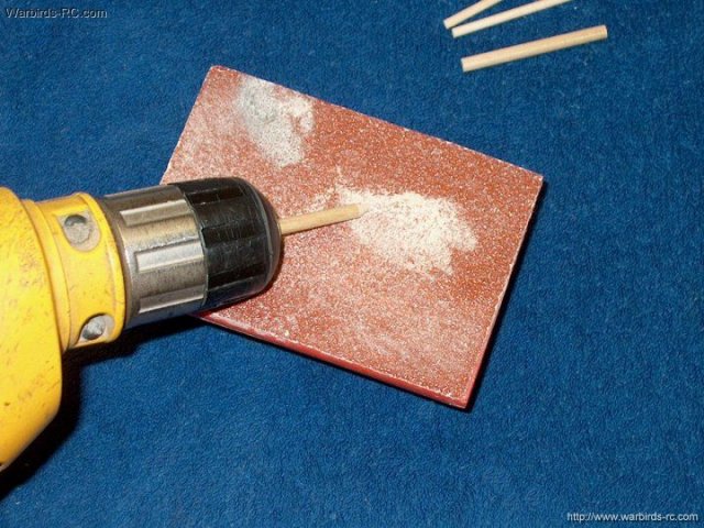
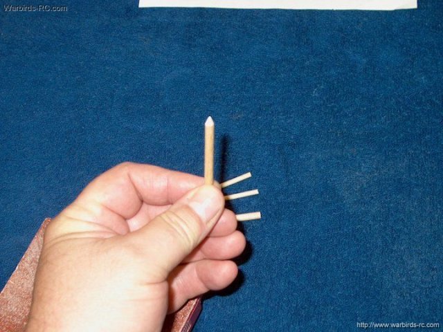
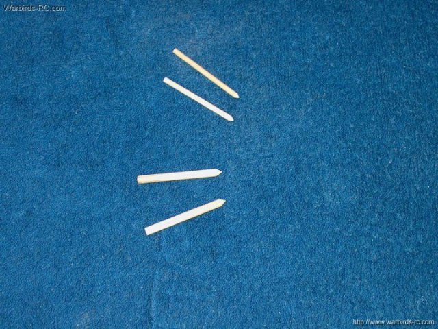
05 - The lumber that comes with the model
is of very good quality | |
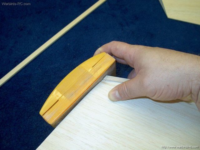
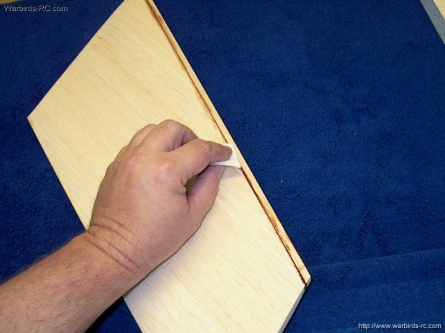
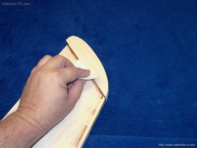
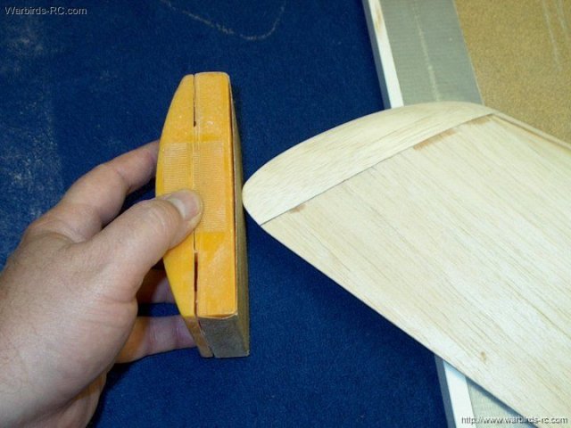
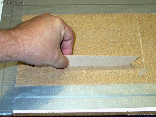
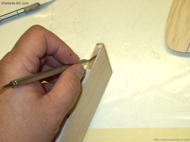
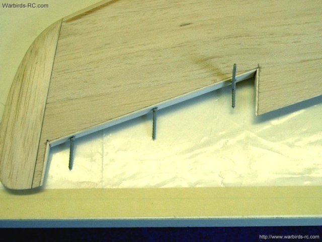
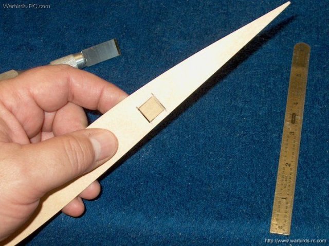
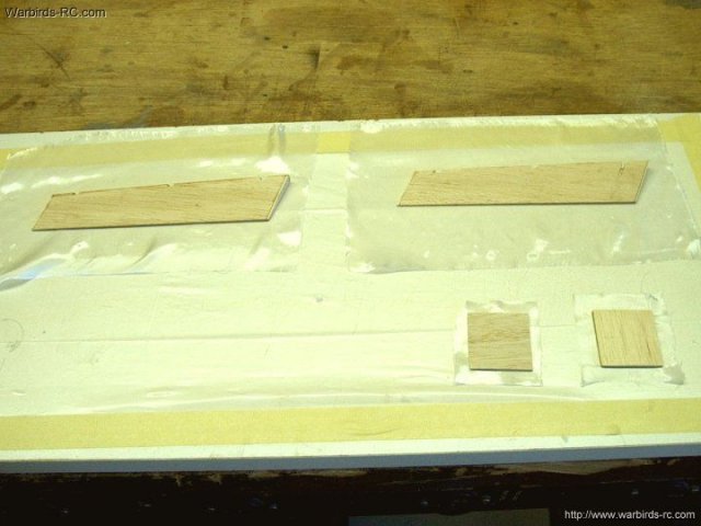
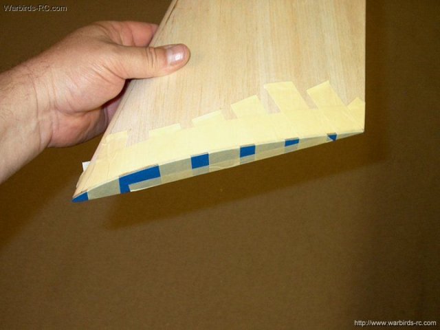
06 - Construction begins with the wings.
As these wings were presheeted, several steps were eliminated.
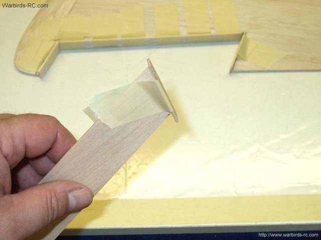
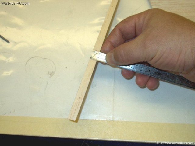
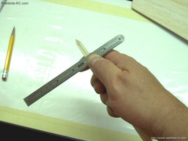
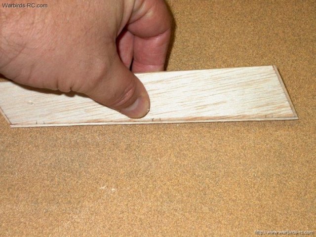
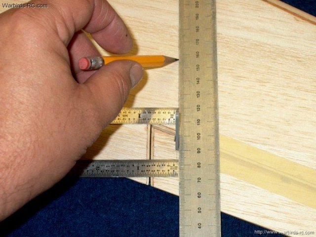
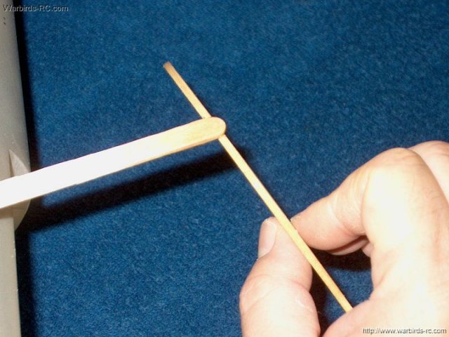
A 1/4" x 1/2" balsa strip is sanded flush with the correct
angle at the wing tip leading edge. Make sure you hold the
strip centered across the leading edge of the wing
| |
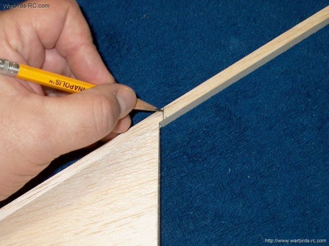
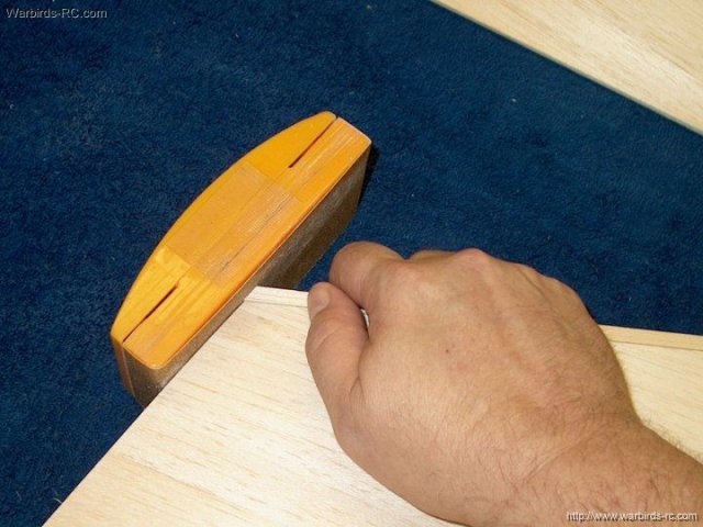
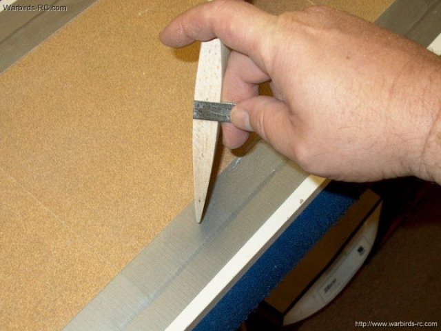
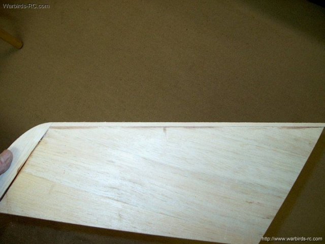
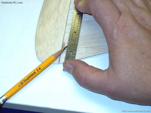
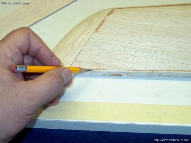
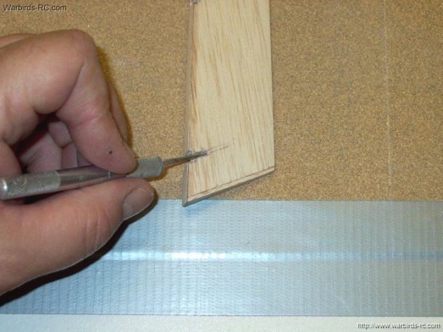
07 - Hole the tip flush and make a mark on
the balsa strip slightly longer than the inside root of the
wing | |
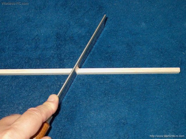
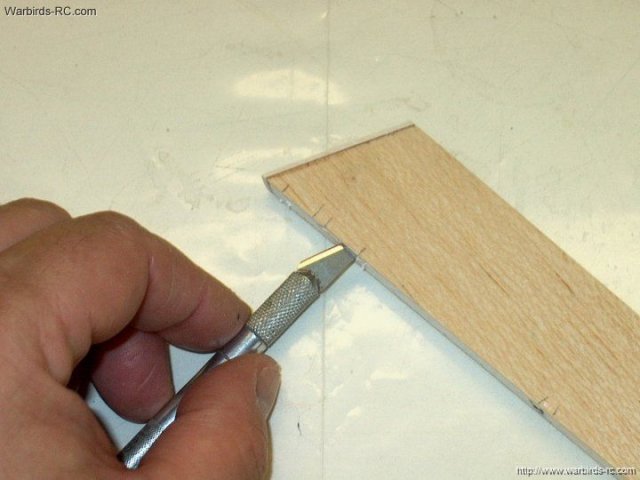
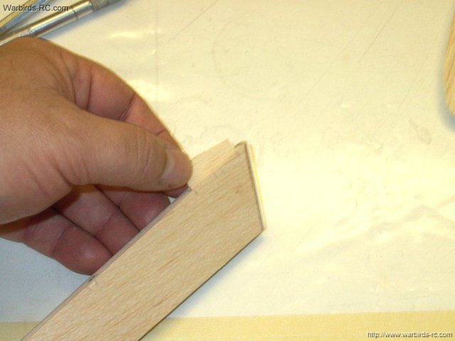
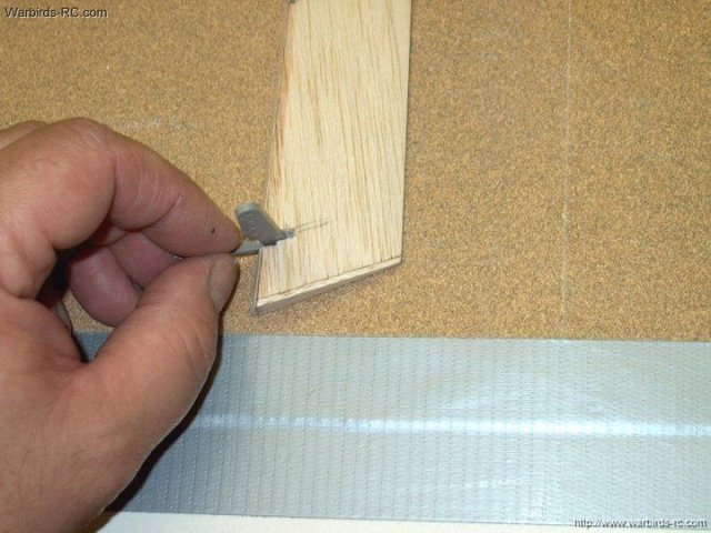
08 - Cut the excess from the balsa strip
at the mark you made | |
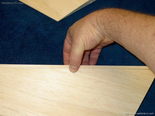
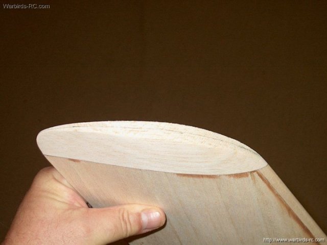
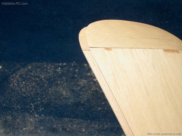
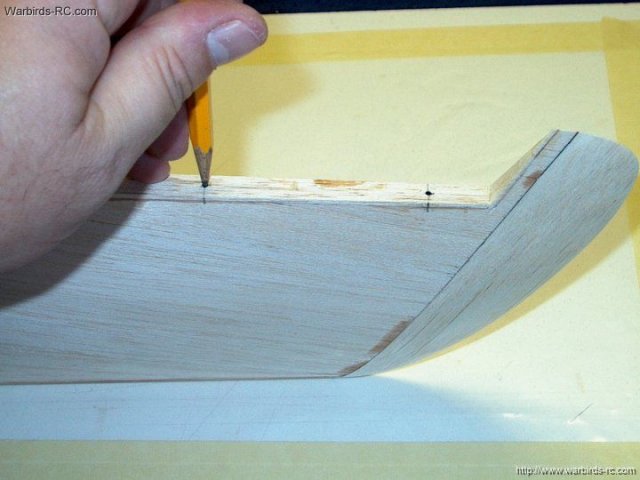
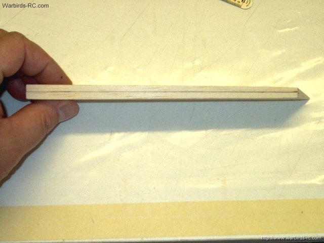
09 - Photo shows the strip flush with the
wing tip to the left and centered down the leading edge
| |
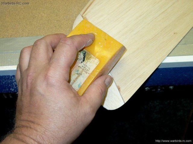
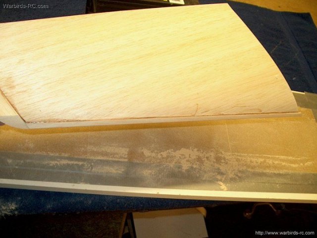
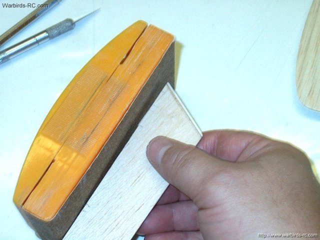
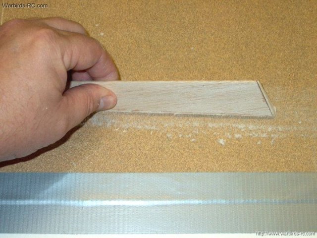
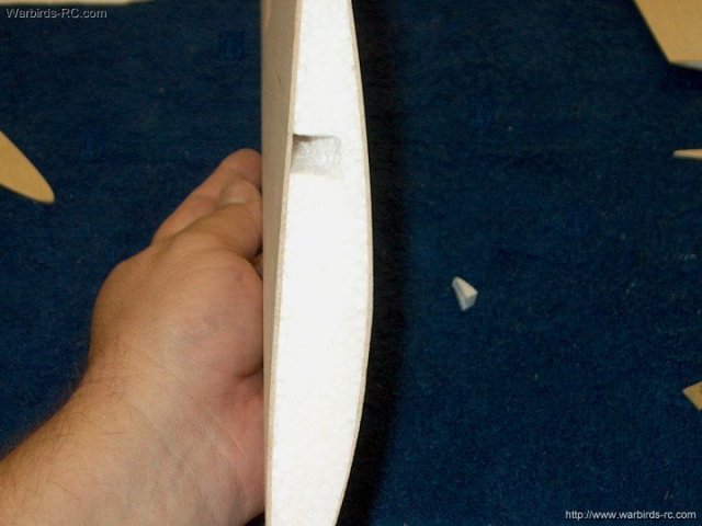
10 - The second wing is prepared by
sanding the tip angle on the 1/4" x 1/2" balsa strip
| |
11 - Strip must be kept centered while
sanding and when gluing | |
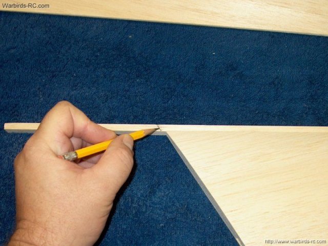
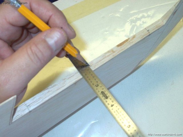
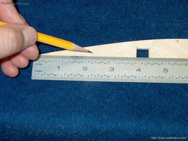
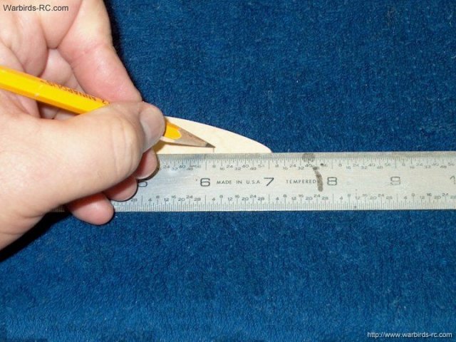
12 - The second strip is marked about 1/4"
from the root of the wing | |
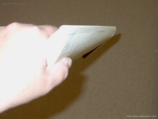
13 - The excess is removed from the balsa
strip | |
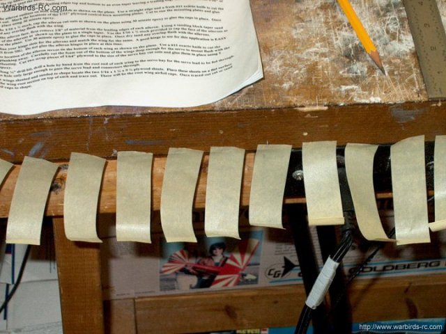
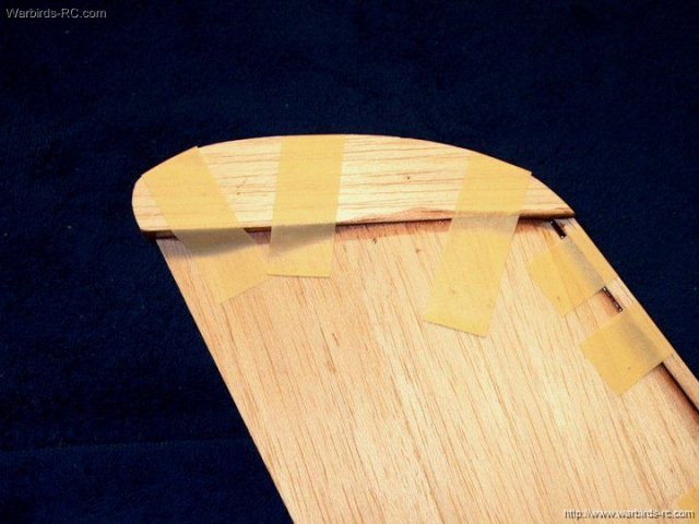
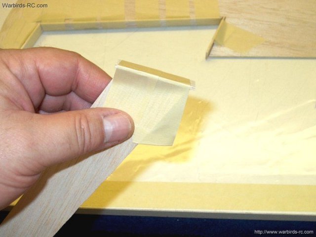
14 - Prepare several pieces of masking
tape around 3" long that will be used to hold the balsa strip
in place. About eight pieces per wing will work fine
| |
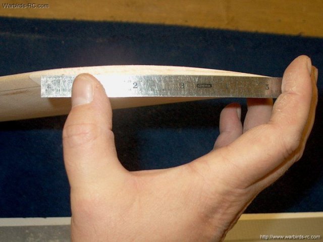
15 - Wings, leading edge 1/4" x 1/2"
strips and wing tips ready to glue | |
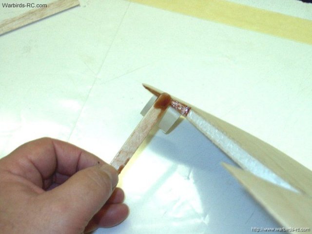
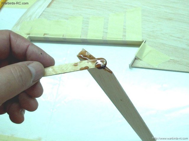
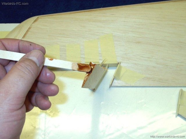
16 - Some 15-30 minute Epoxy is applied to
the leading edge of the wing and the inside of the balsa
strip | |
17 - The strip is positioned over the
leading edge and excess epoxy is removed
| |
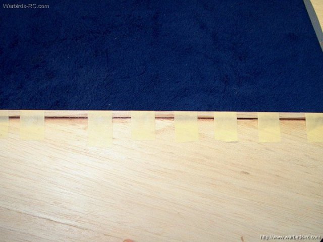
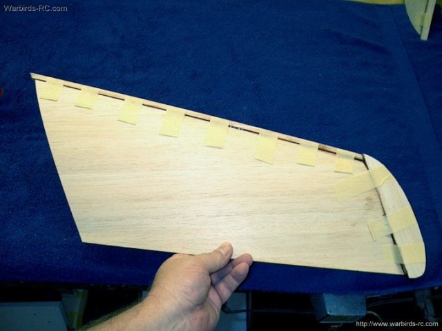
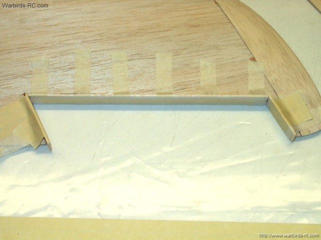
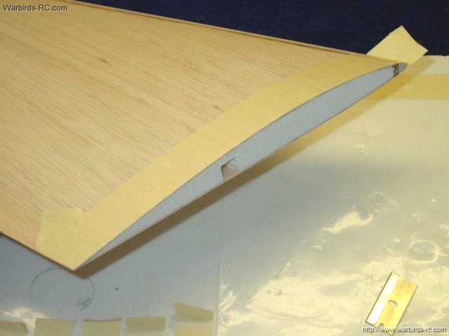
18 - Use the tape strips to hold the balsa
leading edge strip in place. Make sure it is flush with the
wing tip end and centered along the leading edge on both the
top and bottom | |
19 - Make sure the leading edge is flush
with the wing tip root, then apply epoxy to the wing tip
area | |
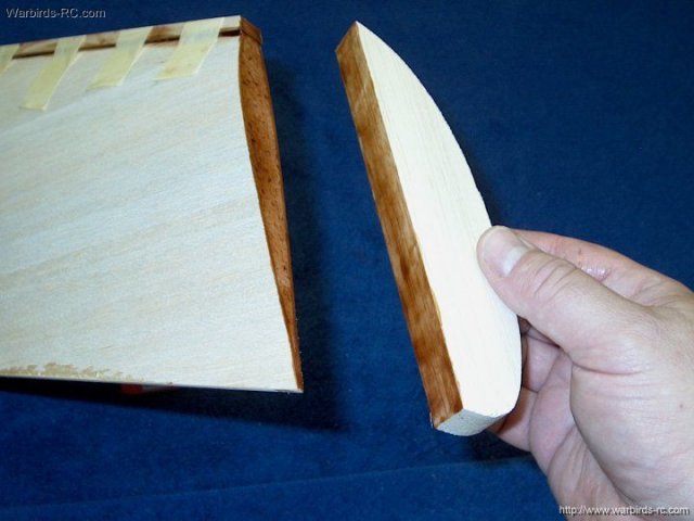
20 - Apply epoxy to the Wing Tip balsa
stock | |
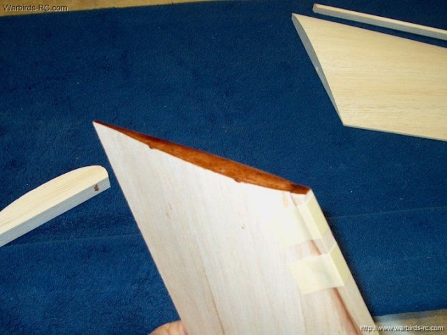
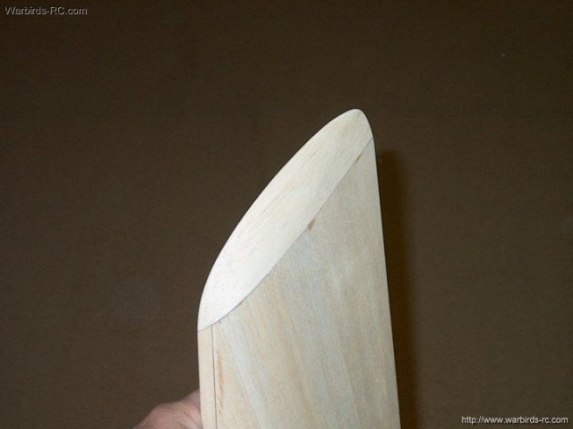
21 - The balsa wing tip is positioned and
excess epoxy is removed. Make sure you position the wing tip
block in the correct direction, with the shallow curve toward
the front as shown | |
22 - Use long pieces of masking tape to
hold the wing tip block in place. Make sure the block is
centered with both the top and bottom of the wing and also
make sure it is flush with the leading edge as shown on the
right side | |
23 - Epoxy is applied to the second wing
leading edge and balsa strip. Keep the strip centered down the
wing leading edge and flush with the outside tip, then clean
the excess epoxy and tape the strip in place
| |
24 - Epoxy is applied to the wing tip area
of the wing | |
25 - Epoxy is applied to the wing tip
block and the block is positioned as shown with the shallow
curve forward | |
26 - The wing tip and leading edge shown
with masking tape in place | |
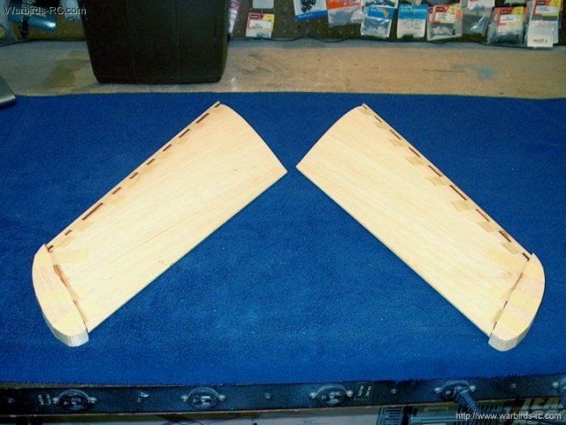
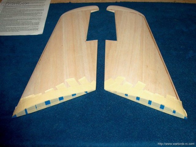
27 - Both wings are waiting for the epoxy
to set | |
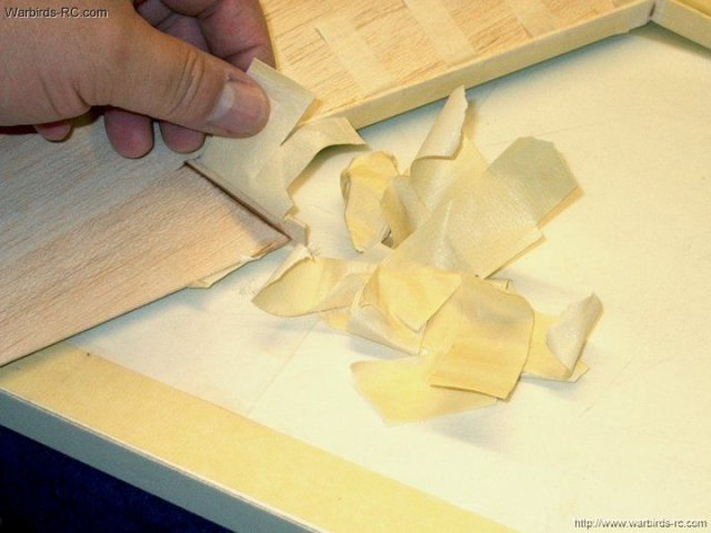
28 - Epoxy has set and tape has been
removed so the wing can be shaped | |
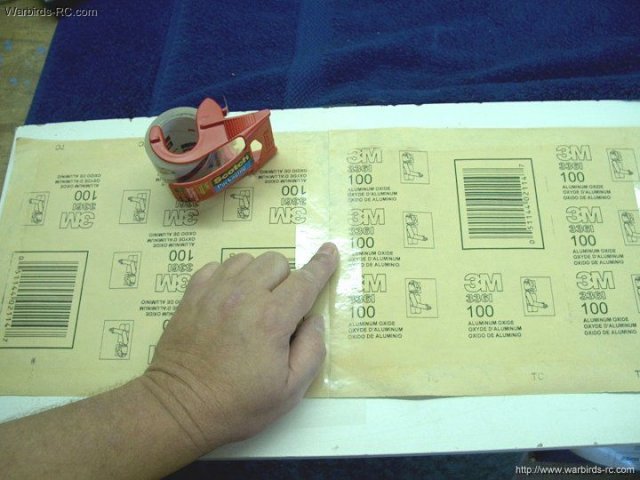
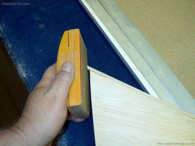
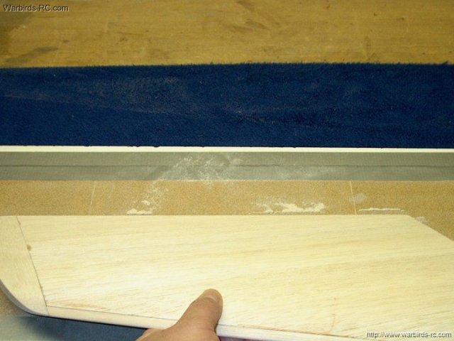
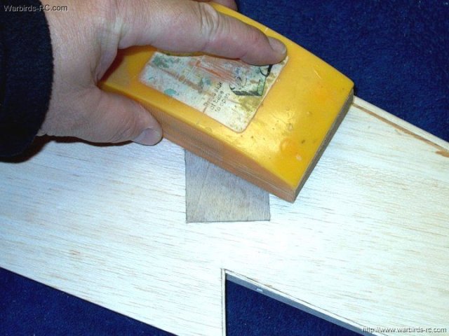
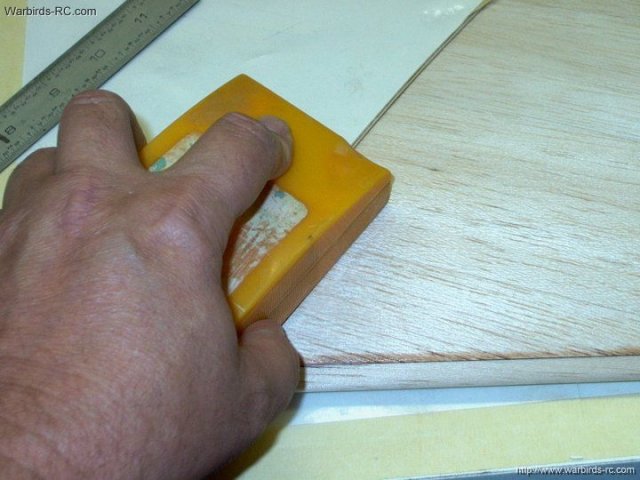
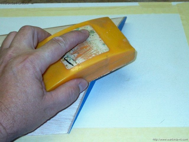
29 - Making a sanding board...I used three
sheets of 100 grit sandpaper and taped them at the seams, then
trimmed the excess tape flush to the outer ends
| |
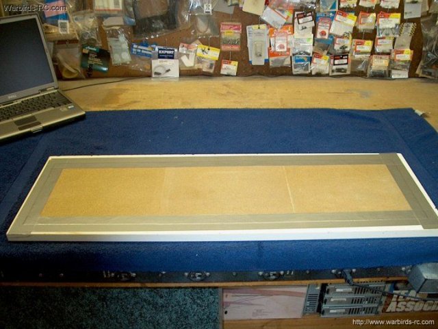
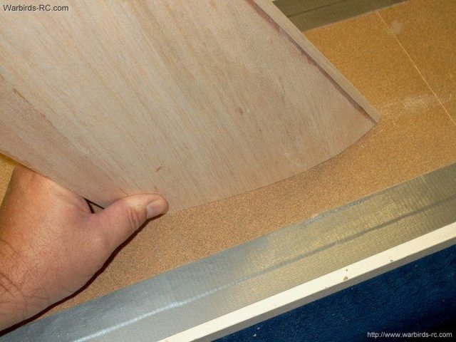
30 - The long sheet of sandpaper was taped
to a two dollar shelf board that is very flat. Only use duct
tape as it is the only one that will stick to the
sandpaper | |
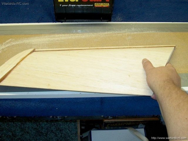
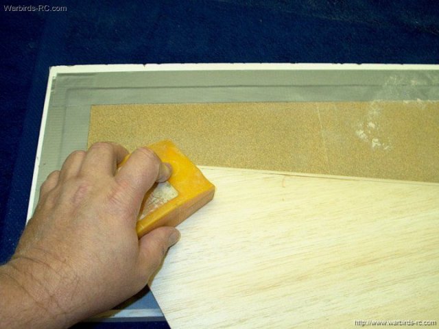
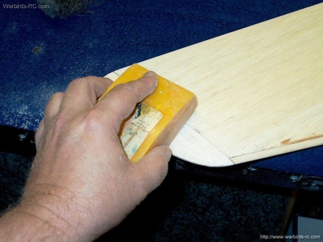
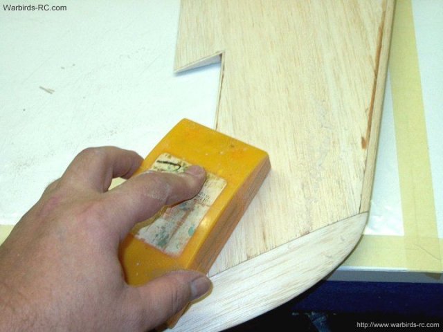
31 - Hold the wing with both hands and
shape the leading edge...it will go surprisingly fast and the
board helps keep your sanding perfectly even across the
wing | |
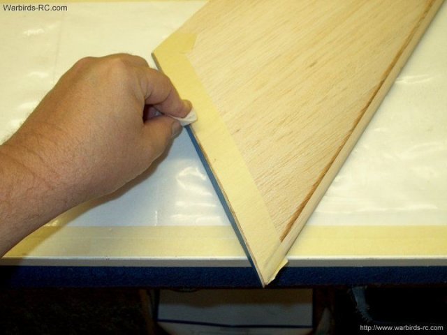
32 - Initial sanding of leading edge spar
now flush with the wing top | |
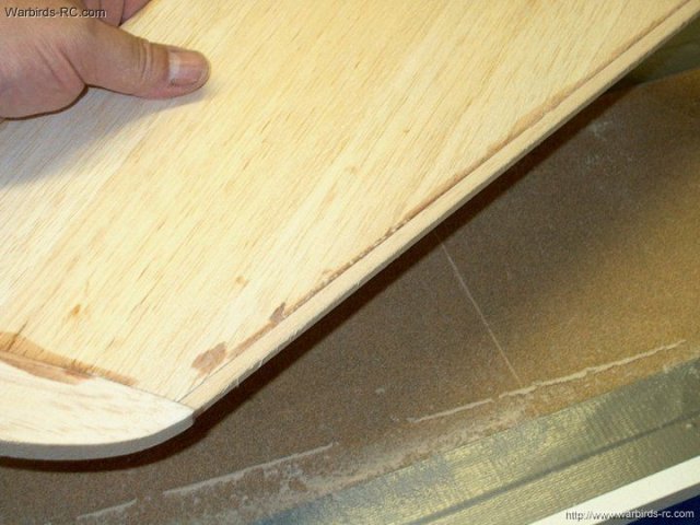
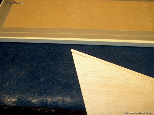
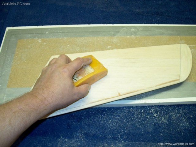
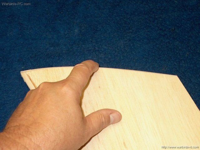
33 - Once both sides are done, you can
drag the wing across the sandpaper toward you and rotate the
wing rear up to make an even leading edge curve
| |
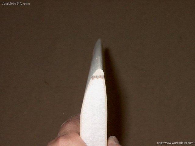
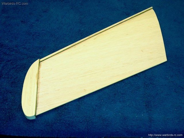
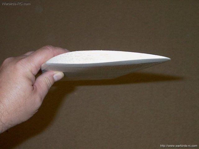
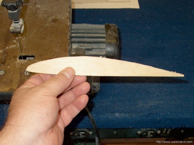
34 - Shaped leading edge completed
| |
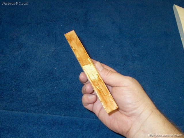
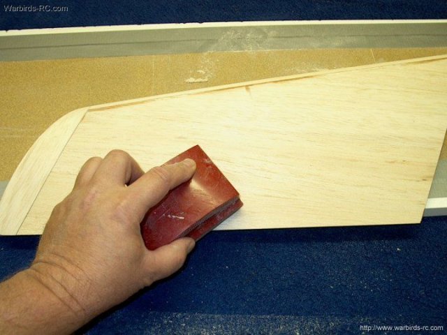
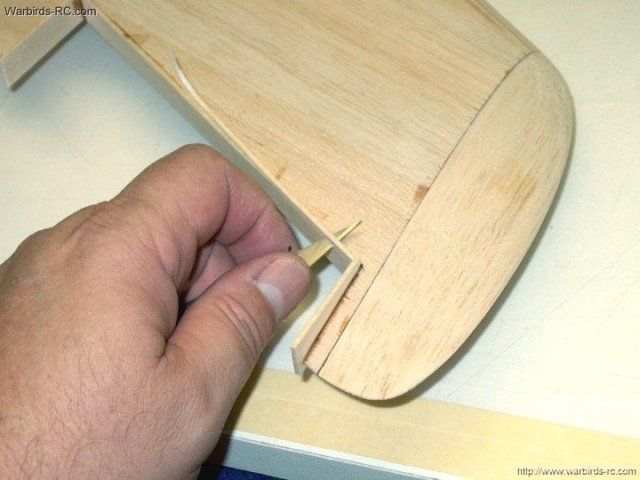
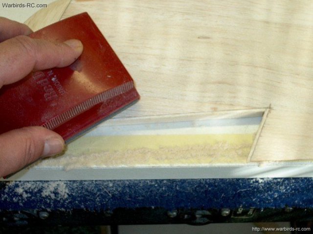
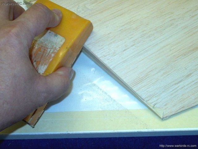
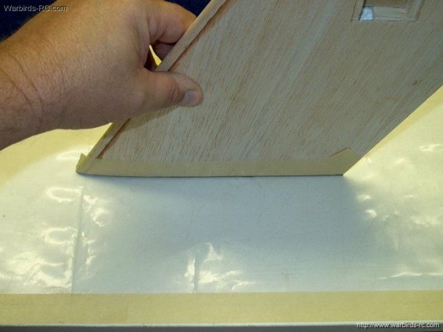
35 - The excess spar at the wing root is
sanded down. Stop just short of it becoming flush so there is
enough spar to finish sand | |
36 - Finish sanding the root tip by
dragging the root across the sandpaper
| |
37 - Wing tip spar is completed
| |
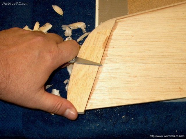
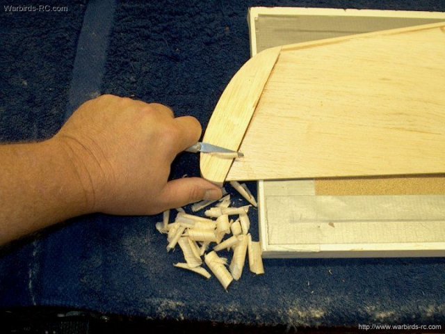
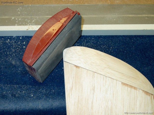
38 - Excess wing tip block is carved away
using a large hobby knife. Be careful to not cut too deep and
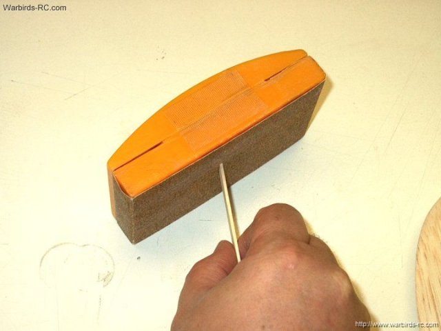
leave some excess to sand | |
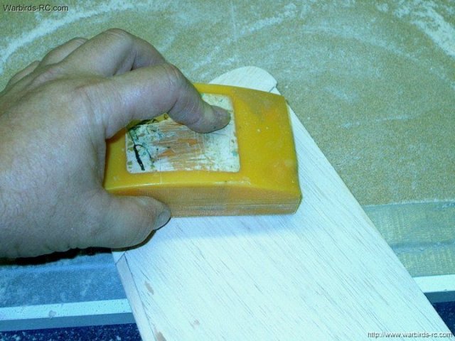
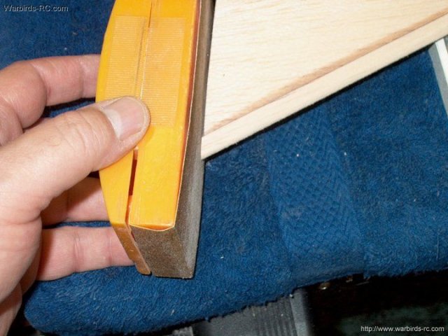
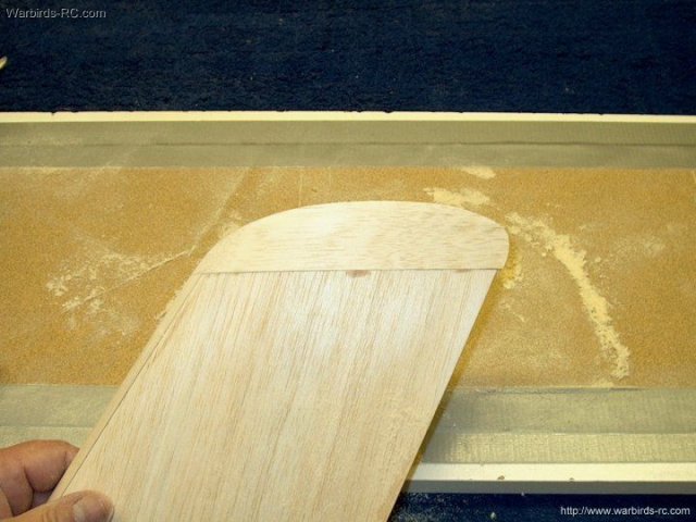
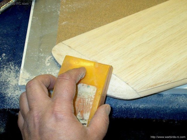
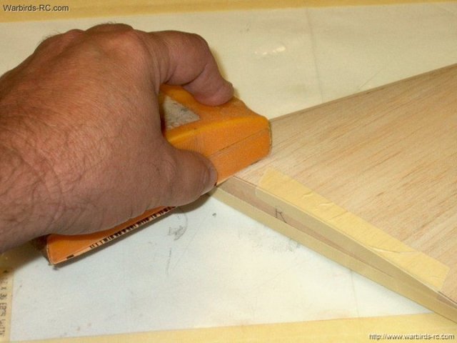
39 - The sanding board and a sanding block
as shown are used to shape the wingtip block
| |
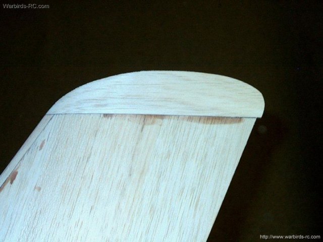
40 - Wingtip Block shaped on top and
bottom | |
41 - Wing tip shown shaped to the
chord | |
42 - The trailing edge is sanded on both
sides to a taper of 1/16" | |
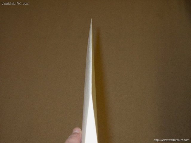
43 - Trailing edge completed
| |
44 - The seams of the wing sheets are
sanded flush. Check and sand the seams on both sides
| |
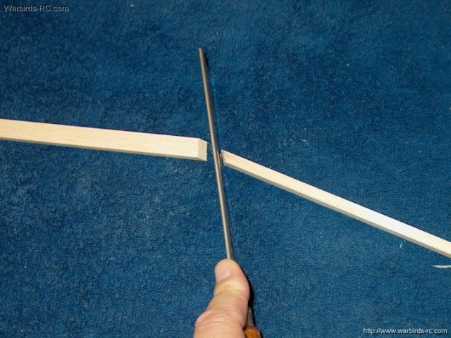
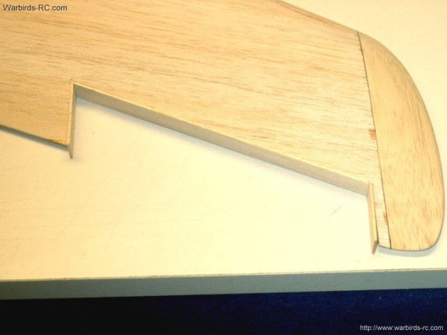
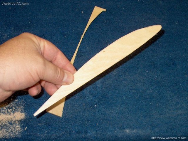
45 - The first wingtip is cut to shape
after the trailing edge is finished
| |
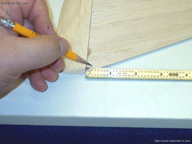
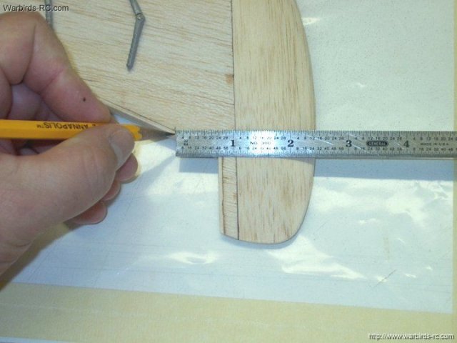
46 - Center marks are made along the
outside edge of the wing tip | |
47 - A center line is drawn through the
marks...this is the line you will sand to when tapering each
side | |
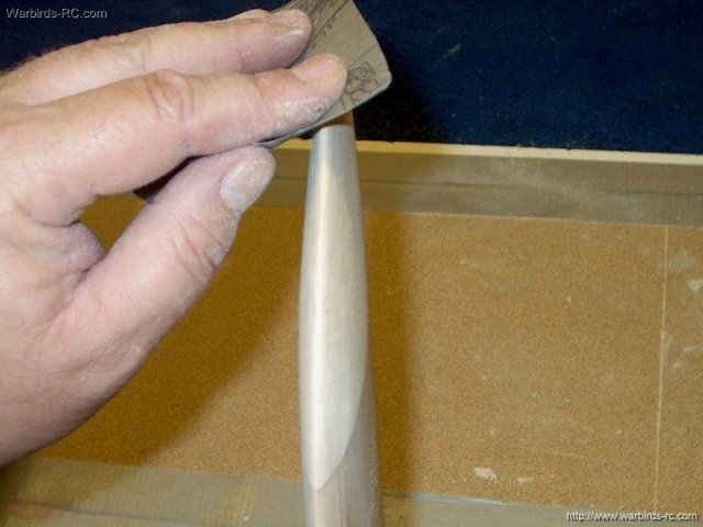
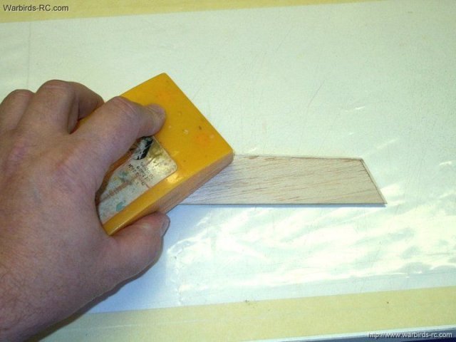
48 - A sanding block is used to taper and
shape the wing tip | |
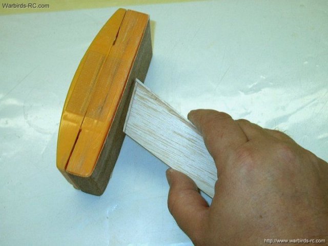
49 - The second side is sanded to the line
and shaped | |
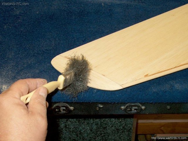
50 - Keep dusting while you sand to make
sure you are sanding straight | |
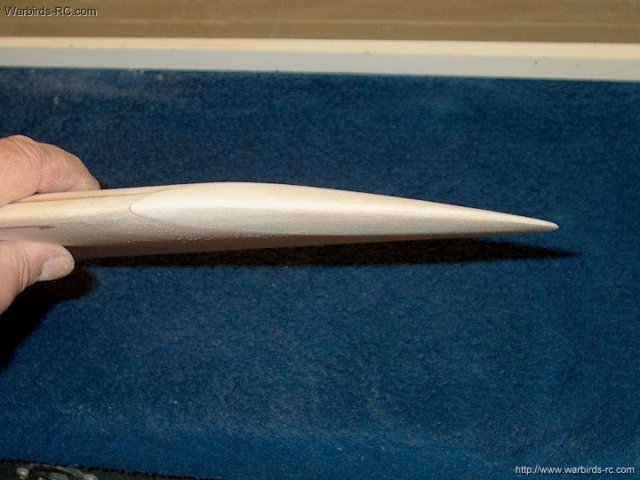
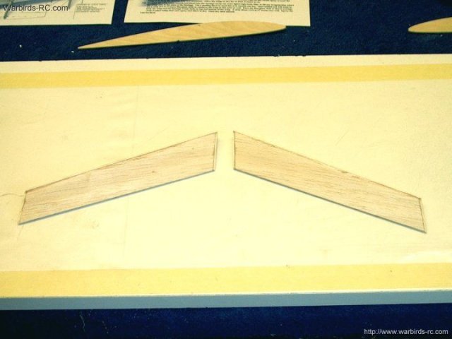
51 - Wing Tip taper completed
| |
52 - Another view of the shaping that was
done to the wing tip | |
53 - The second wing is sanded just like
the first, starting with shaping the leading edge
| |
54 - The bottom leading edge has been
shaped to the contour of the wing | |
55 - The top leading edge is shaped the
same way. Check it often to make sure you are sanding evenly
across the wing | |
56 - Leading edge shaping shown
completed | |
57 - Sand down the root tip flush to the
wing | |
58 - Root tip finished
| |
59 - Carve away the large portion of the
balsa tip so there is less to sand later. Be careful not to
over trim | |
60 - The tip is sanded on both sides to
the contour of the wing | |
61 - The trailing edge is again sanded to
a 1/16" taper | |
62 - Next the seams are sanded
flush | |
63 - Seams on the bottom of the wing are
sanded | |
64 - The finished wing is placed evenly
over the second wing and a sanding block is used to shape the
trailing edge | |
65 - Both Wing Tip trailing edges should
match | |
66 - A center line is drawn down the
second wing tip | |
67 - Both sides of the wing tip are
tapered and shaped to the line | |
68 - Fine sandpaper is used for final
shaping of the tip | |
69 - Wing tip shaping completed
| |
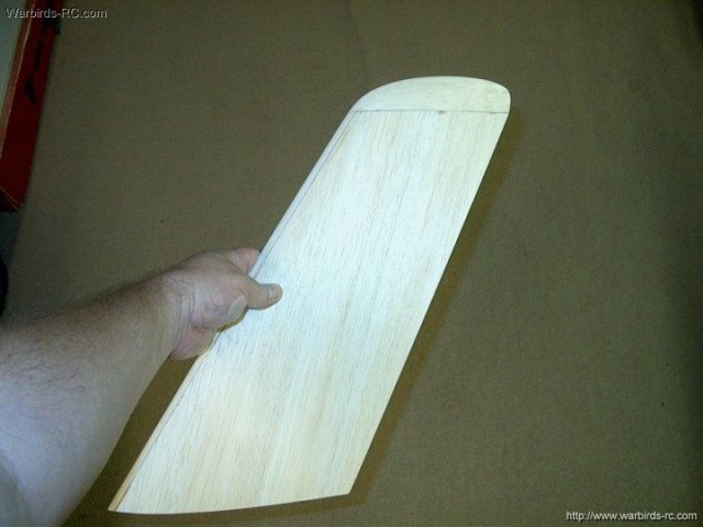
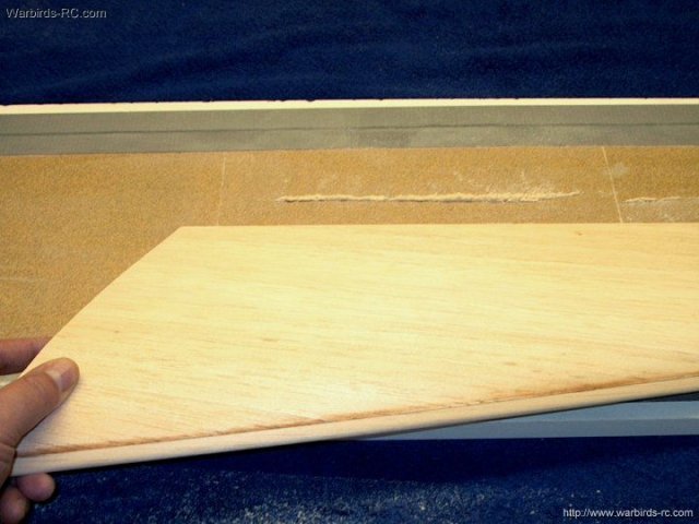
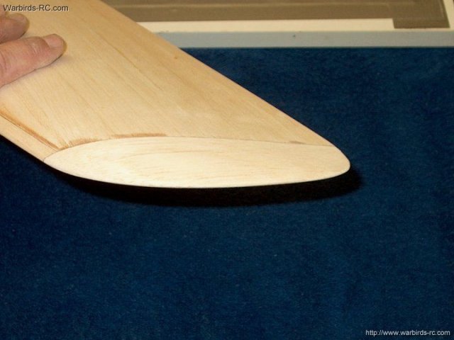
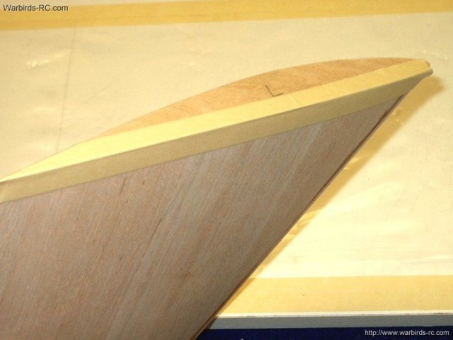
70 - Top view of the wing to show final
shape | |
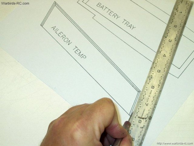
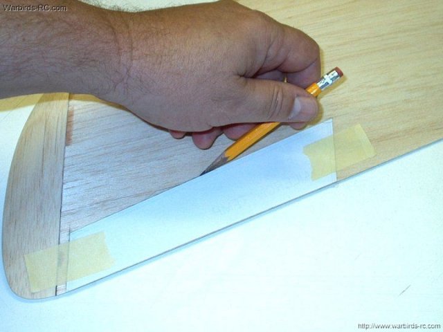
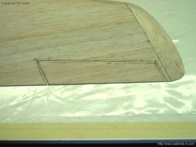
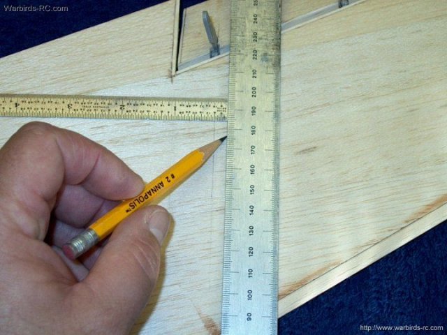
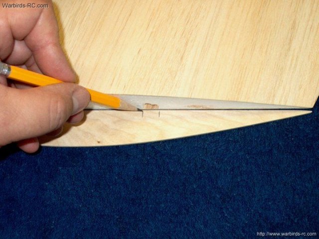
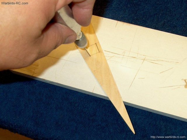
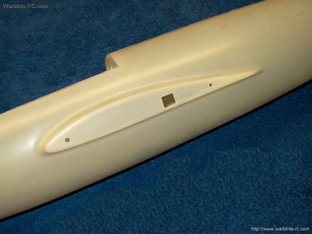
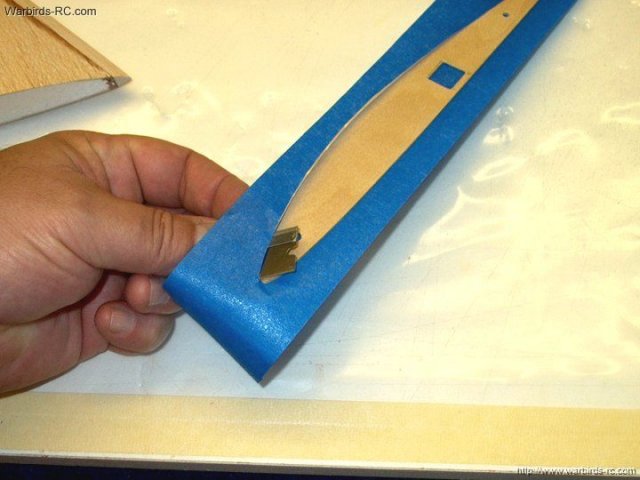
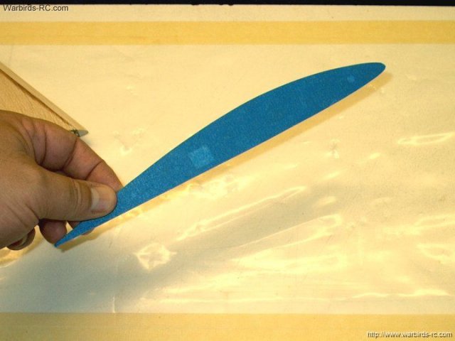
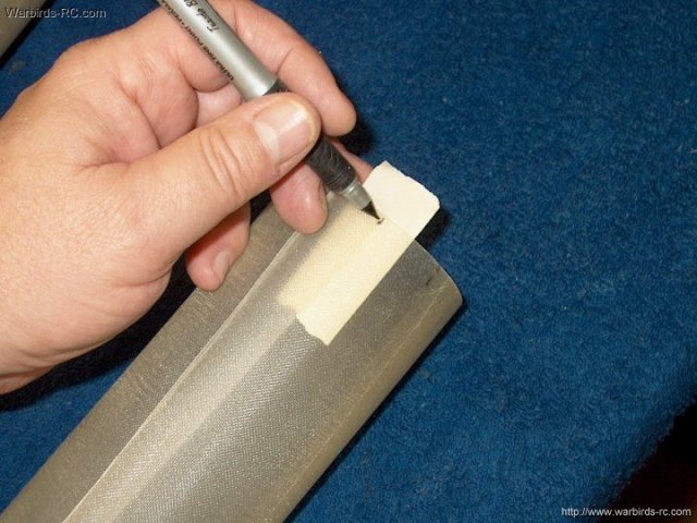
71 - Carefully cut out the Aileron
Template | |
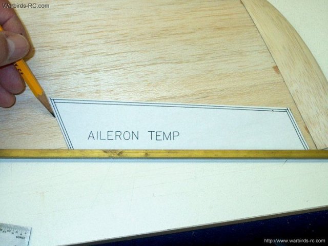
72 - A piece of brass square was used as a
straight edge and placed flush against the bottom of the wing.
The template is placed flush against the square and then
spaced 1/4" to the inside of the wingtip seam. Position the
template with the narrow end toward the wing tip, then draw
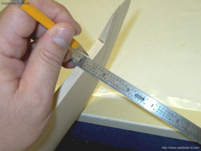
the Aileron shape on the wing | |
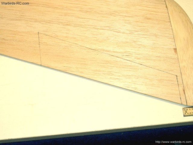
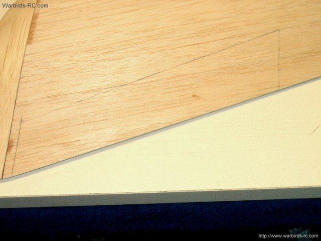
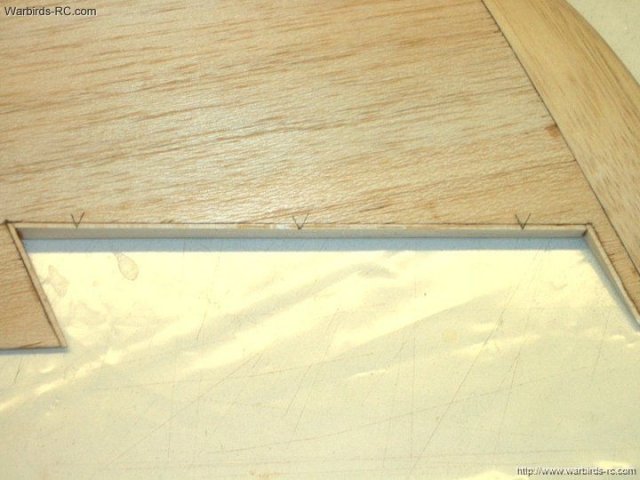
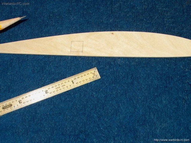
73 - Aileron shape shown drawn on the
wing | |
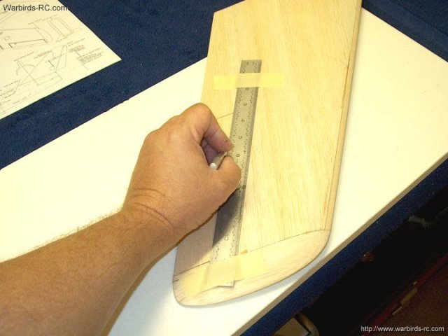
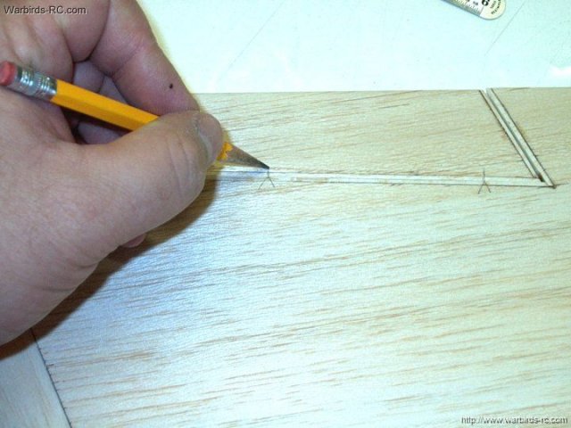
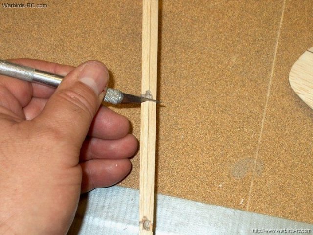
74 - Using a straight edge and a very
sharp hobby knife, carefully cut out the Aileron. Be sure to
hold the knife perpendicular to the wing so you do not cut
down at an angle | |
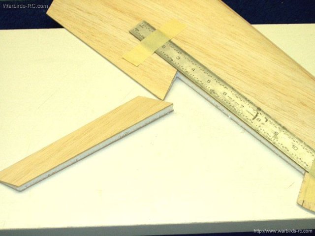
75 - Aileron shown cut from wing
| |
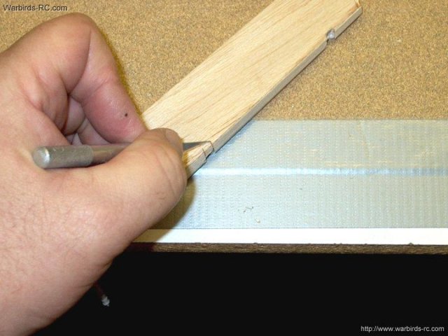
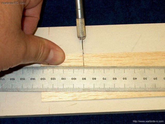
Keep the knife square and cut 1/8" from
the front of the Aileron | |
The Aileron is lightly sanded flush
| |
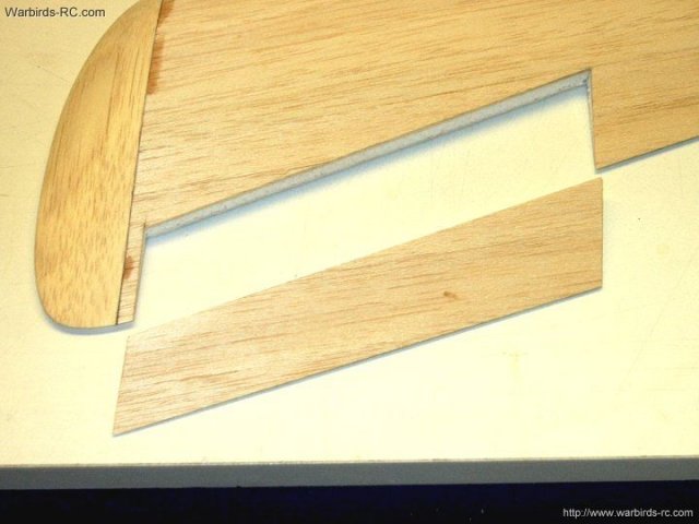
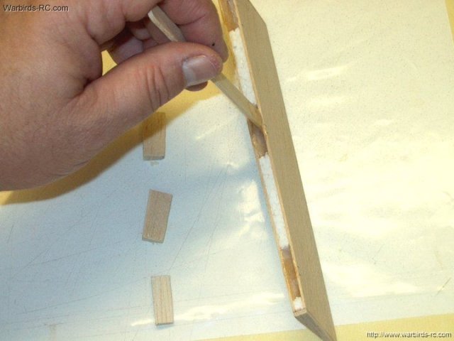
The 1/16" x 1/2" wide balsa strip is
slightly angled to fit the wing | |
Use the strip to cut three pieces to sheet
the inside of the wing in the Aileron well. Do not glue
yet | |
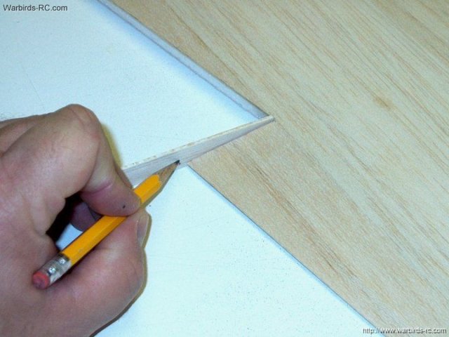
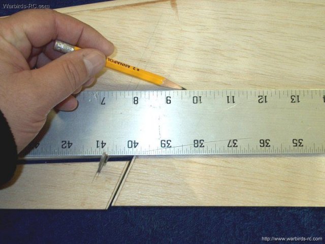
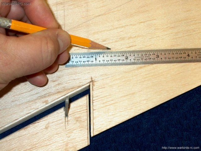
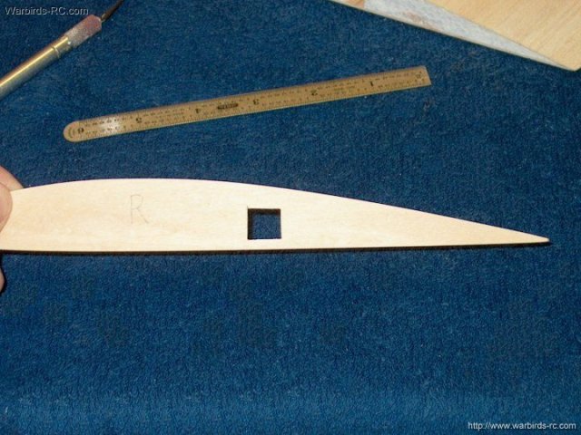
The second wing half is marked 1/4" from
the seam for template position | |
A vertical line is drawn to help align the
template | |
The template is flipped and used to marke
the Aileron cutout. Be sure to keep the smaller end toward the
wing tip | |
Template shape transfered to the
wing | |
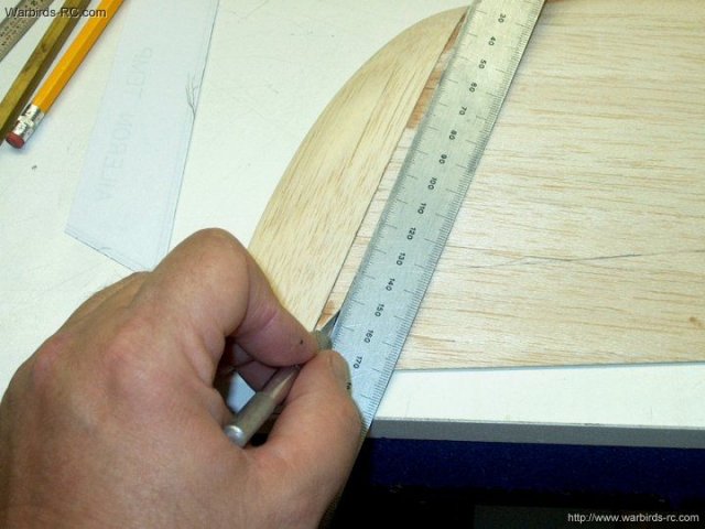
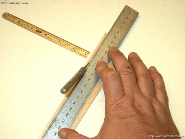
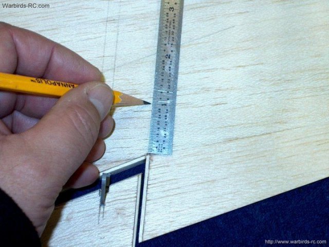
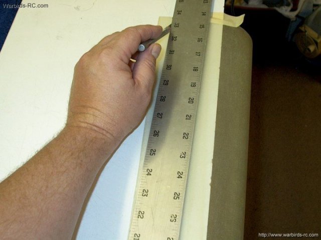
Once again, use a fresh blade and an
straightedge to cut out the Aileron. Keep the blade
perpendicular when cutting and make several shallow
passes | |
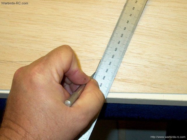
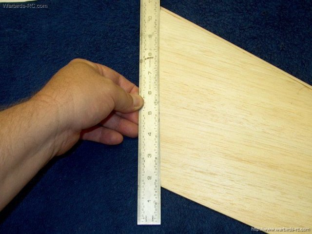
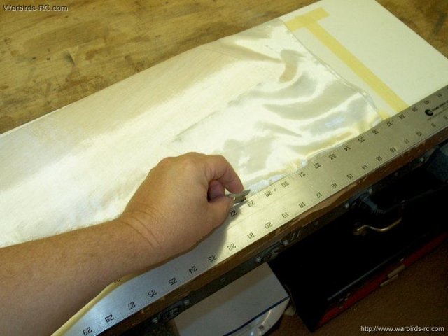
A ruler helps keep the line nice and
straight | |
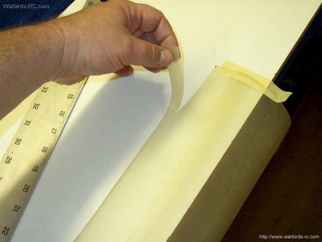
Second Aileron cut from wing
| |
the 1/16" x 1/2" balsa strip is once again
cut to box in the Aileron area of the wing
| |
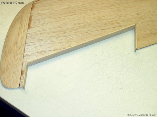
Pieces shown cut , fitted and ready to
glue | |
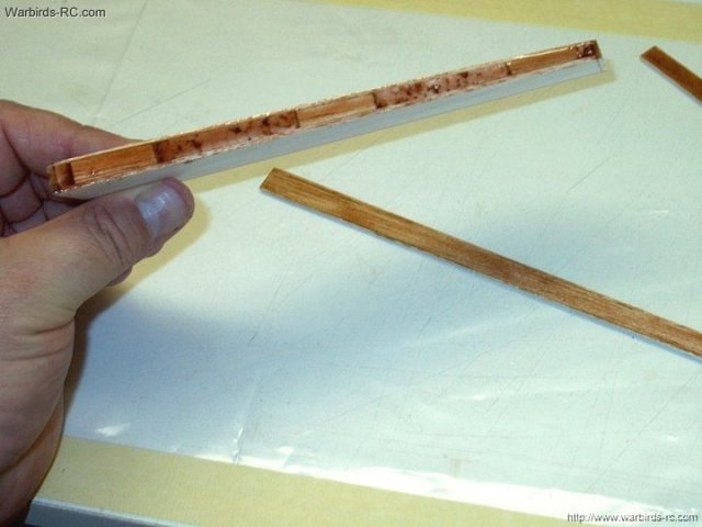
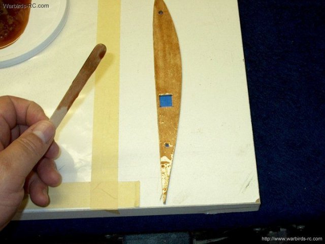
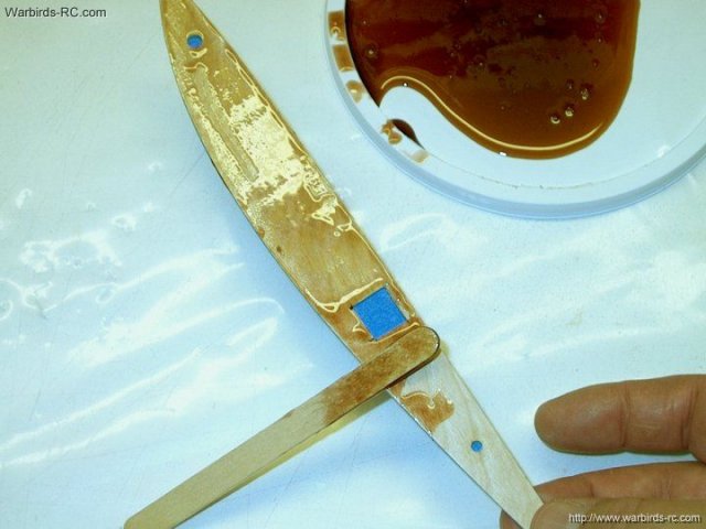
Fifteen minute epoxy was used to mount the
balsa strips | |
Epoxy shown being applied to the Aileron
area of the wing | |
Next, epoxy is applied to the ends of each
Aileron and balsa strips are cut for small Aileron end
caps | |
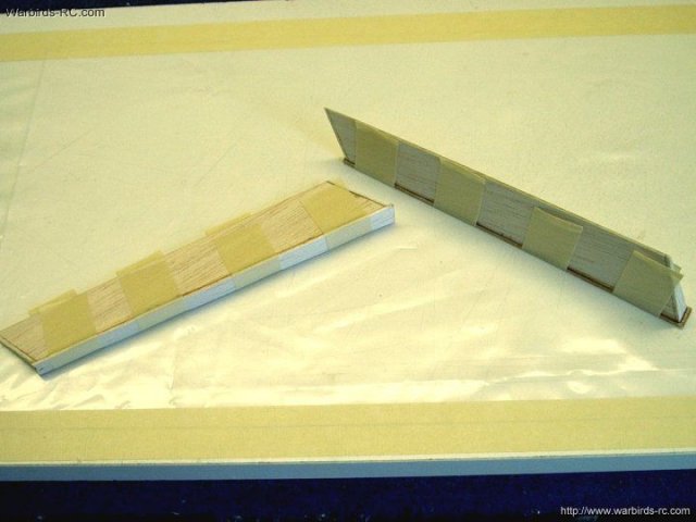
End cap strips shown installed and held in
place with masking tape | |
Second Aileron is prepped for end cap
strips | |
End cap positioned and secured with
tape | |
Once the glue has set, carefully remove
all the masking tape. Sand the end caps on the Ailerons to
match the shape | |
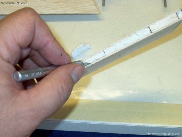
Carefully shave off the larger portion of
balsa with a hobby knife | |
The strips are sanded flush to the
wing | |
The other wing is sanded flush, top and
bottom | |
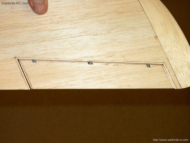
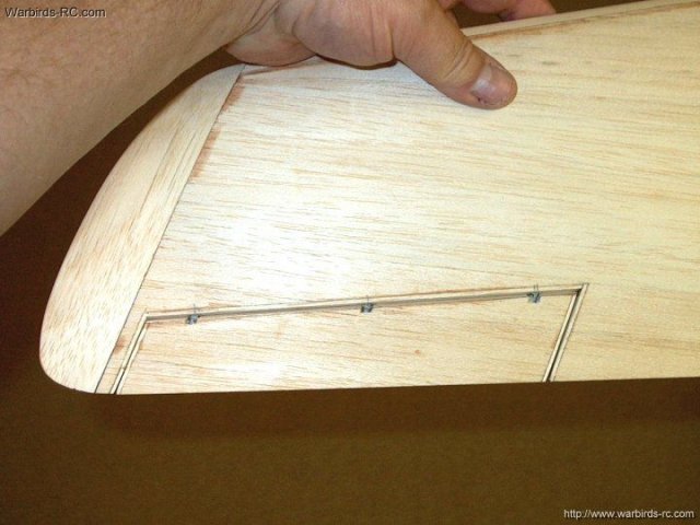
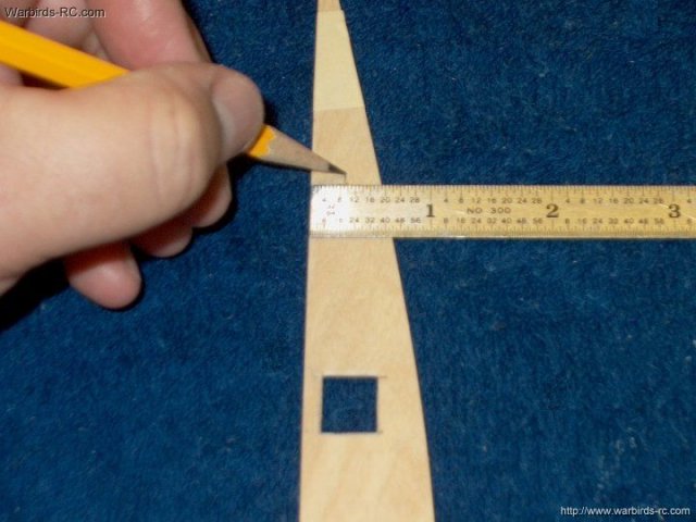
You have the choice of using either Easy
Hinges for Aileron mounts, or an alternate method. Heavy duty
1/8" pin hinges are shown. To install, marks are made 3/4"
from each end of the Aileron well for hinge location
| |
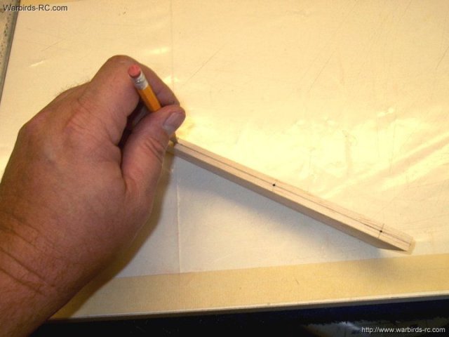
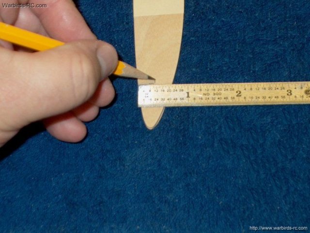
The middle pin location is measured dead
center. All locations shown | |
A center mark is made on the wing
| |
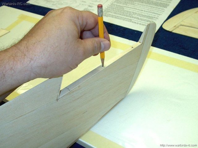
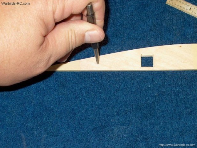
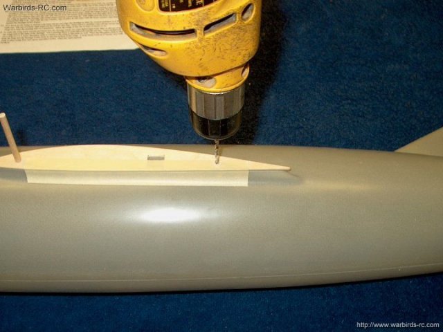
Once you have the three centerlines drawn,
a pencil is slightly pushed into the balsa at each location to
start the mounting holes | |
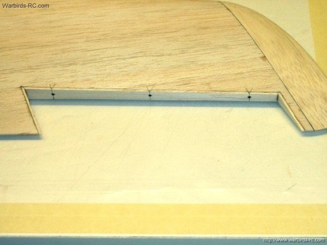
All three holes prepared to drill
| |
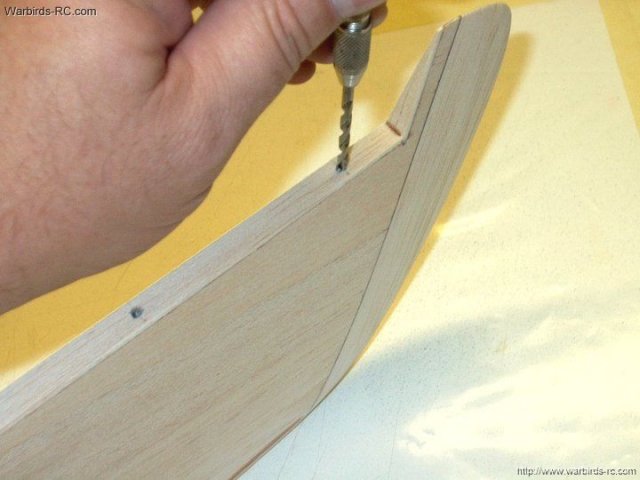
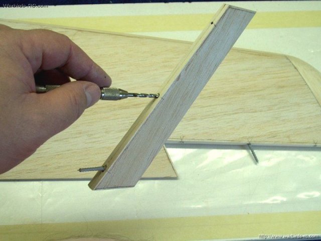
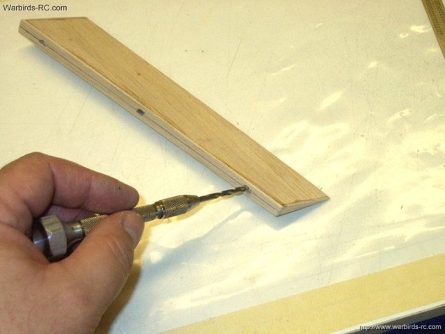
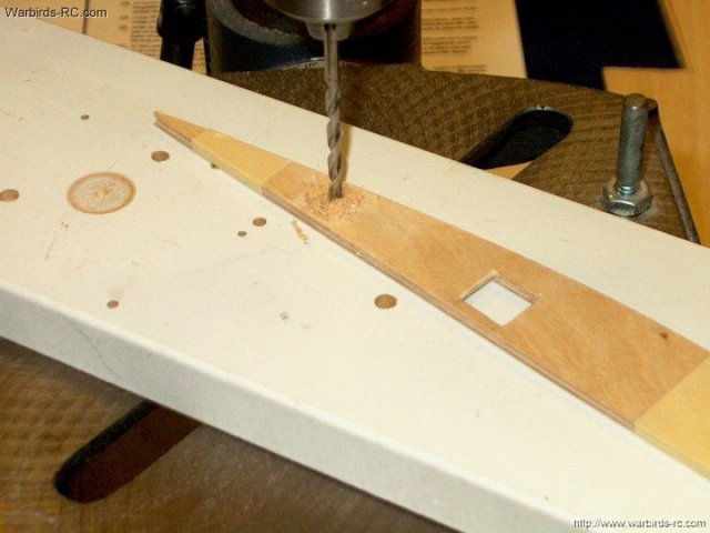
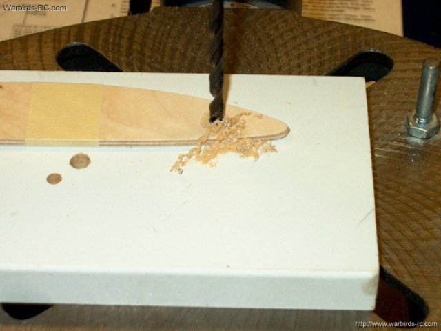
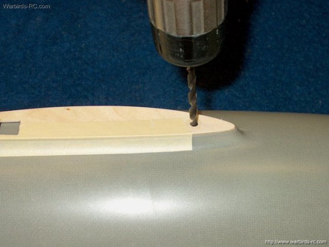
Start the bit straight down, then drill at
an angle parallel to the side | |
The second wing is marked
| |
Cross lines are drawn next to the center
marks | |
The pencil is used once again to start the
holes, then they are drilled | |
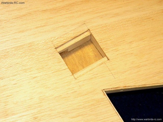
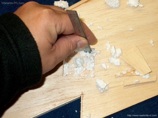
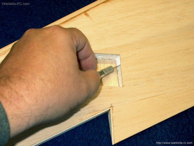
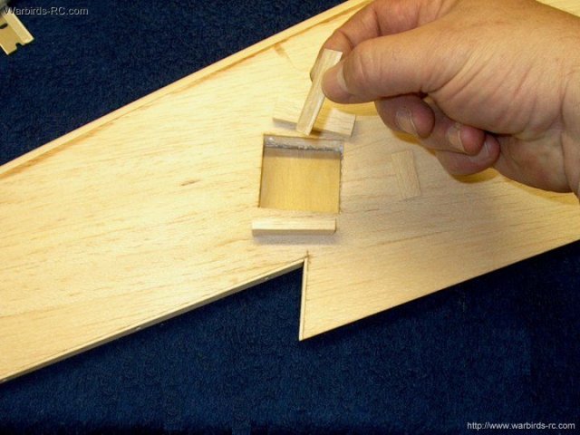
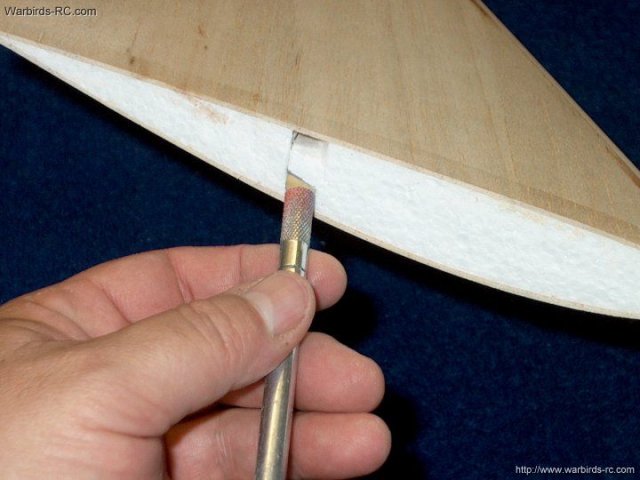
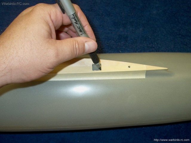
The Aileron is placed and centered in the
wing, then pin locations are transfered. Use a knife to cut
out a 1" wide hole in the foam | |
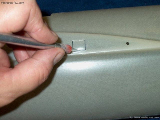
The foam is removed with a hook
tool | |
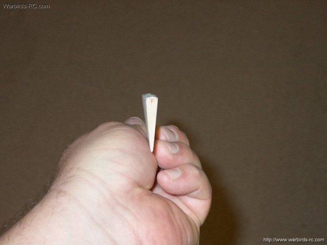
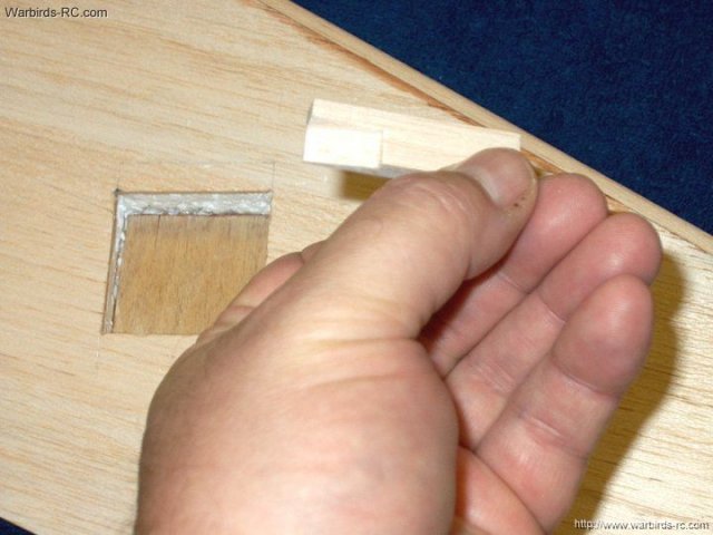
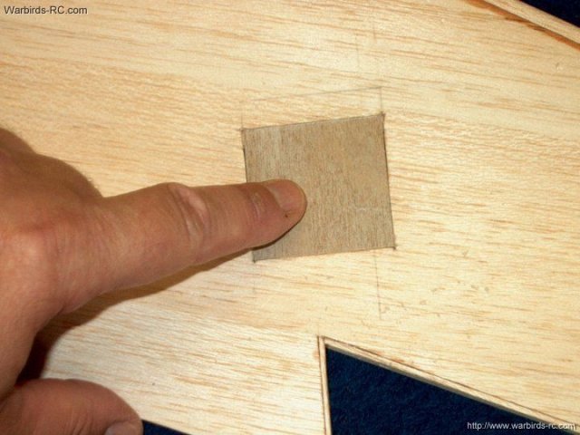
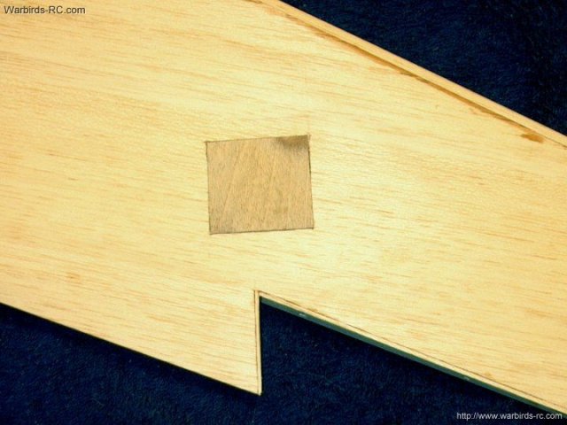
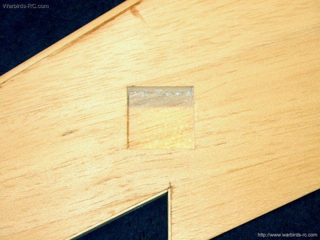
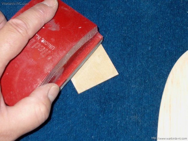
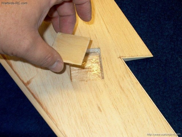
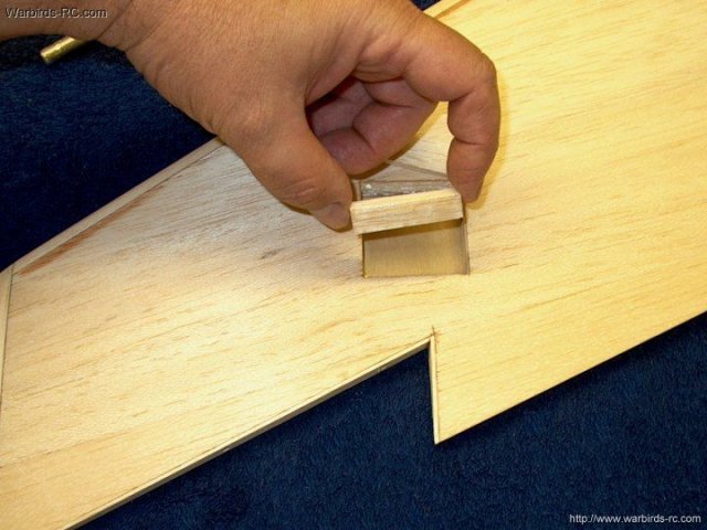
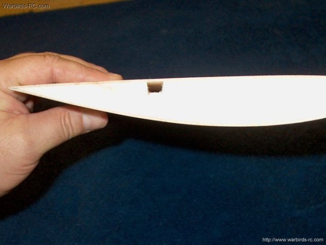
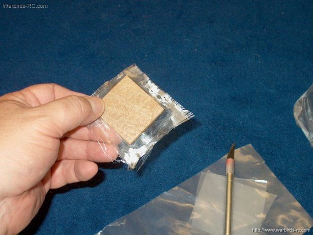
Make a balsa block tapered to fit the
opening. This is done at each pin location to add strength to
the area | |
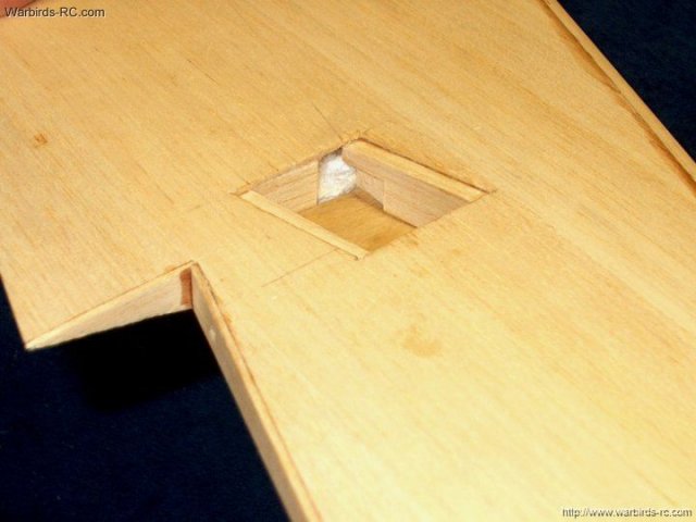
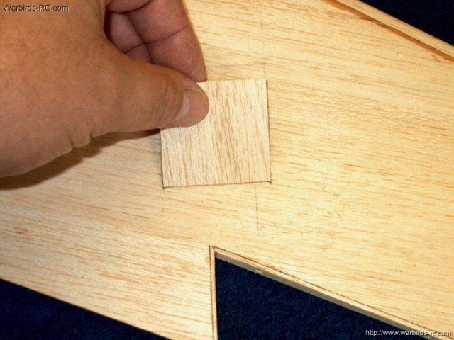
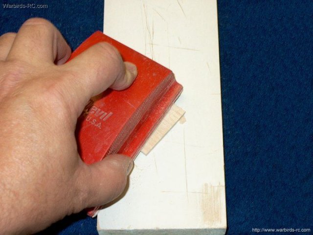
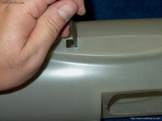
The 1/2" wide block is installed and
sanded flush to the Aileron | |
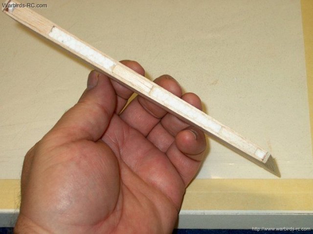
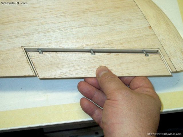
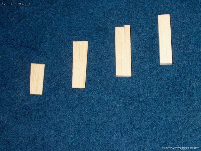
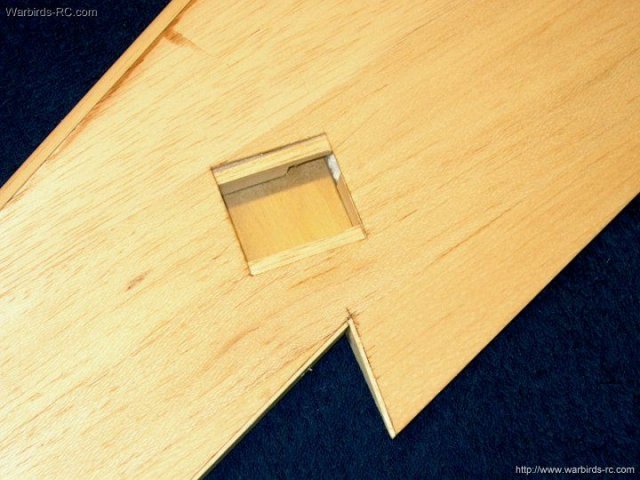
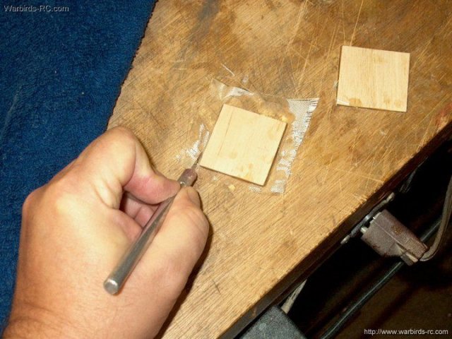
Photo shows all three blocks fitted and
ready to glue | |
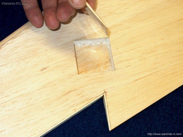
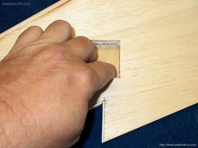
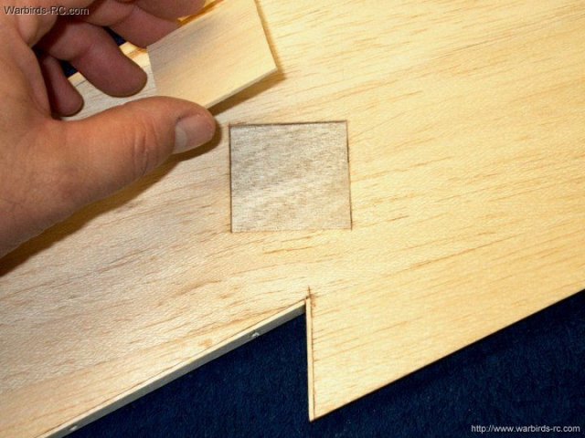
The blocks are removed and 5 minute epoxy
is applied and the blocks installed flush. If you get too much
epoxy, the blocks may hydraulic on you during installation and
not sit completely in place, so push them in a bit deeper and
the excess epoxy should squeeze out the top sides. Clean
excess epoxy with a paper towel | |
The second Aileron is being prepared and
blocks are glued | |
Next, apply 15 minute epoxy to the Aileron
face and strip | |
The strips are mounted to the face and
held in place with masking | |
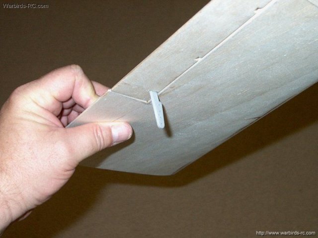
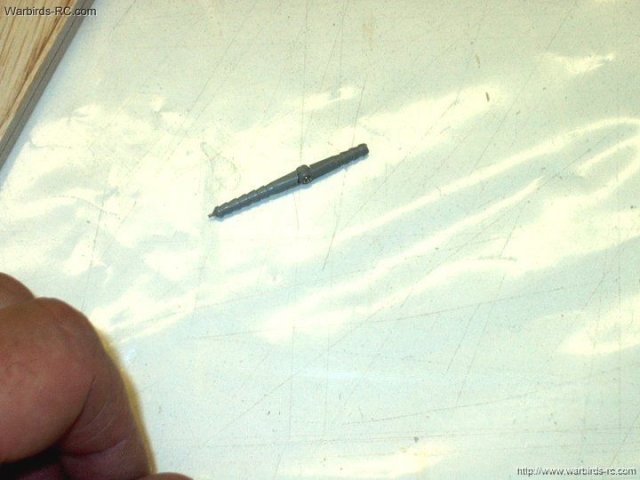
Hinge pins are installed in the wing for
fit. A Hinge with Horn is used on the inside mount
| |
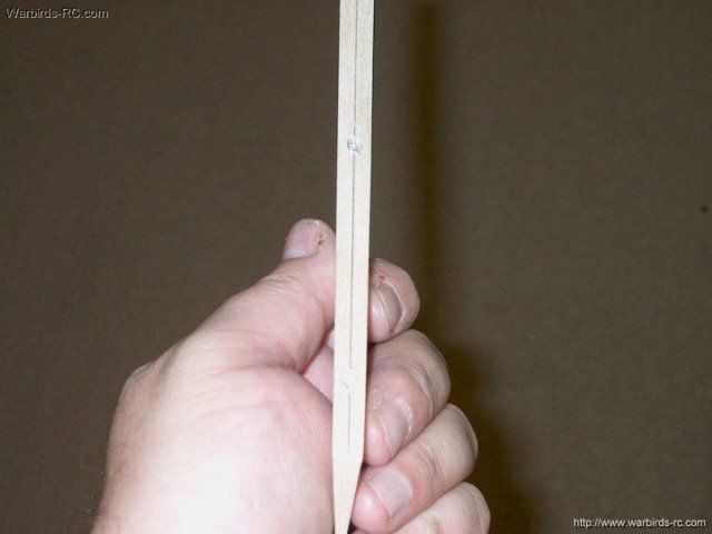
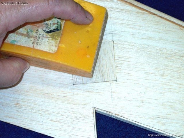
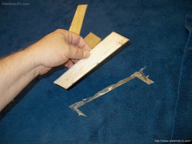
The long front strip is sanded flush to to
the Aileron | |
The ends are sanded flush
| |
Ailerons ready to shape
| |
Fit of Aileron in wing opening shown,
about 1/32" space on each side | |
Center marks are made on the
Aileron | |
A center line is drawn
| |
Hinge mark locations are drawn. Make sure
it is centered on the ends | |
Cross lines are drawn at the hinge pin
locations | |
Holes are started with pencil point
| |
Hinge holes are drilled with a 1/8" bit at
each location. Test fit in the fuselage often to check for
mis-alignment or binding | |
Ruler is placed along each side of the
horn and marks are made | |
Hinge and location marks shown
| |
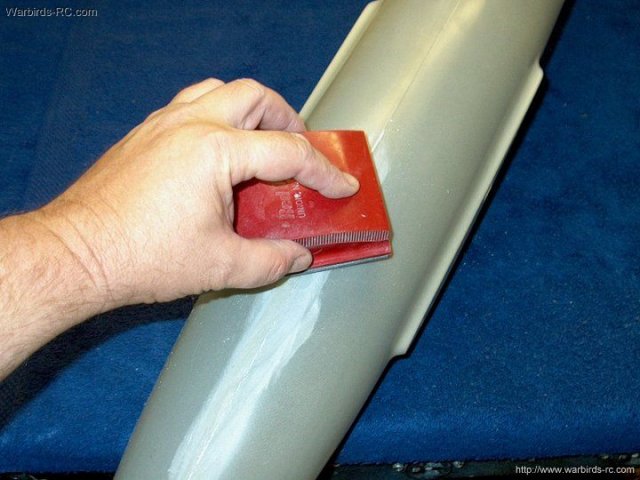
Carefully sand a taper to center on the
Aileron | |
Angle shown sanded and centered
| |
Hinges are installed as well as the
Aileron Note the areas cut away for the hinges, which allows
center pivot at the Aileron | |
Aileron installed
| |
Underside of wing, showing nice clean horn
installation | |
The second Aileron is drilled for
hinges | |
Holes are shown drilled down the
center | |
The end pin needs to be shortened to
fit | |
Sand an angle on the leading edge of the
Aileron. Sand to the center line | |
A slot is cut for the hinge with the
horn | |
The hinge is fit to the Aileron
| |
Use a hobby knife to cut slots for hinge
movement | |
The back of the slots are cut with a sharp
knife | |
install the Aileron in the wing and check
for fit and movement | |
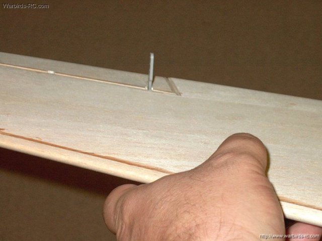
Photo of the horn as seen from the
bottom | |
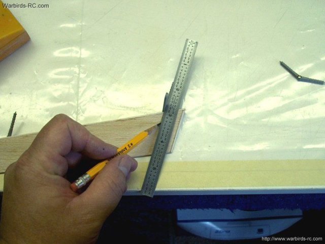
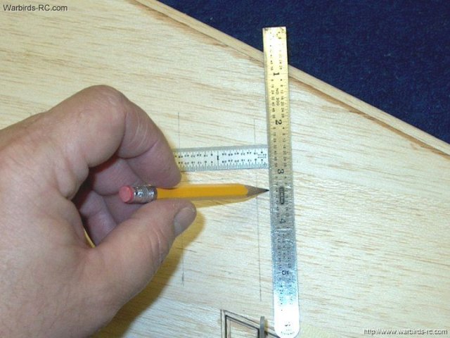
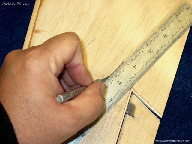
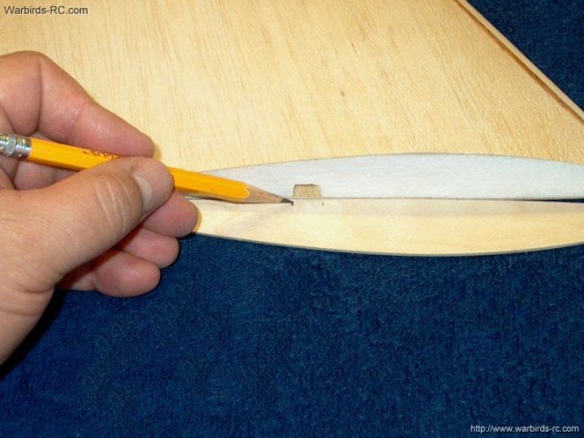
A ruler is used to draw a line for horn to
servo alignment | |
Two 1/8" square harwood sticks were
installed in the wing Aileron wire runs and a yardstick was
placed against these runs, then a line was drawn to indicate
the path of the wires | |
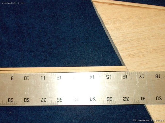
Photo shows yardstick parallel to and
against the wood sticks | |
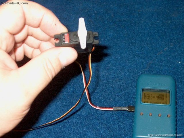
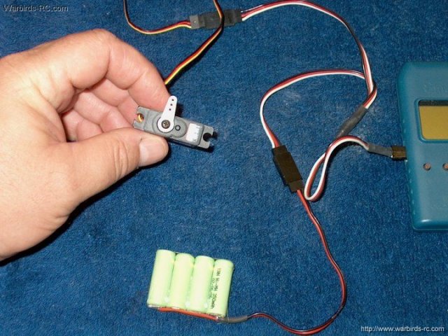
Use a receiver or device to center the
servo | |
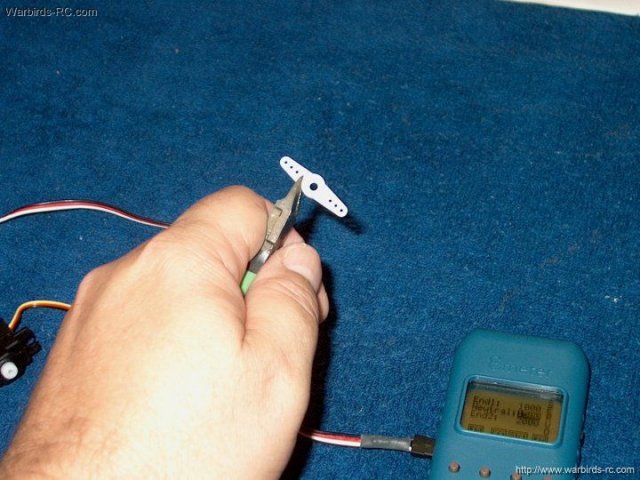
One side of the servo horn is
removed | |
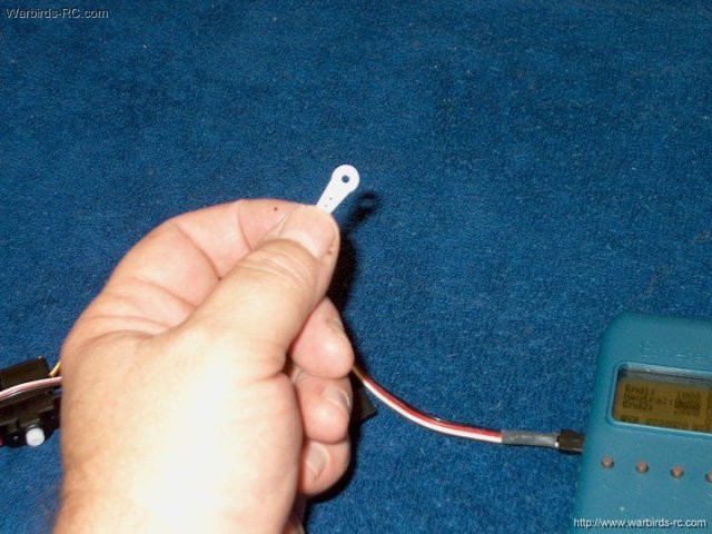
The servo horn is rounded with a sanding
block at the cut end | |
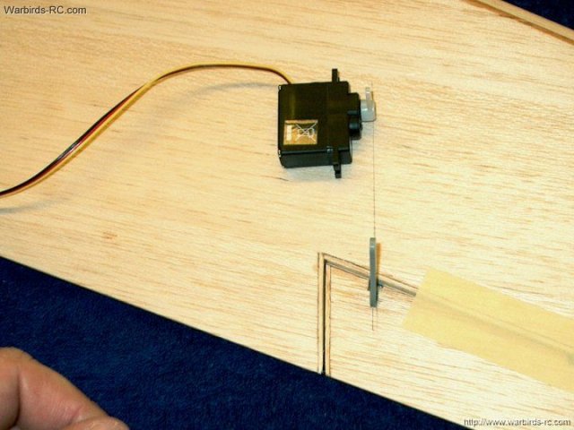
Servo is placed so its horn is aligned
with the Aileron horn | |
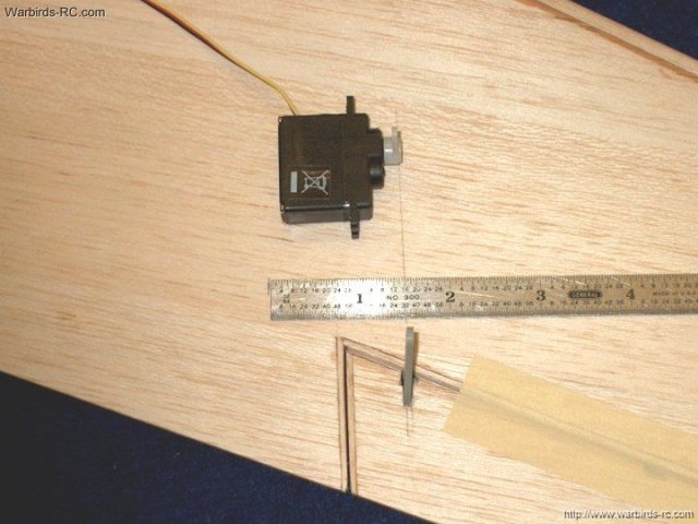
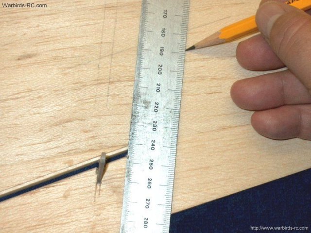
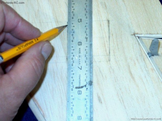
A mark is made 1 1/2"from the servo horn
line | |
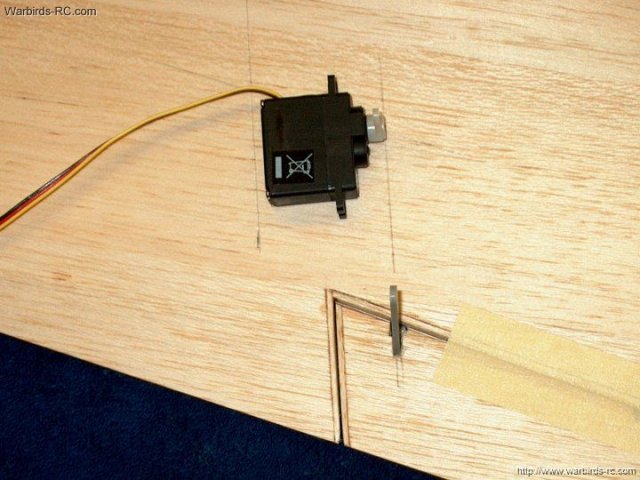
A line is drawn to mark the bottom area of
the servo hole (left) | |
A second line is drawn 1/4" past the servo
horn line | |
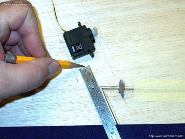
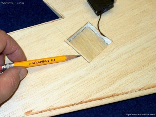
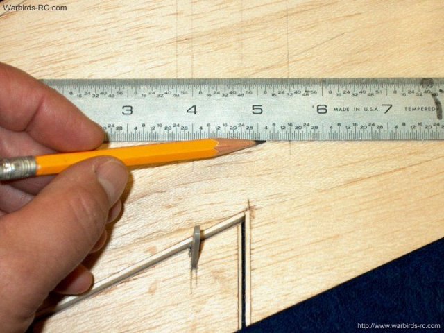
The bottom is marked 1" from the Aileron
area on the wing as shown | |
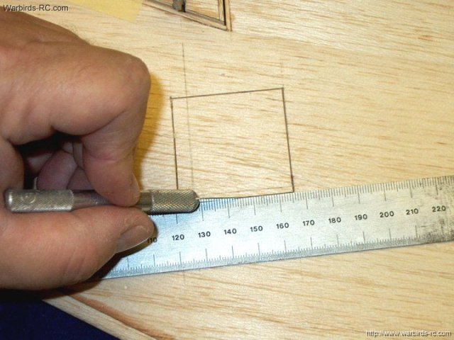
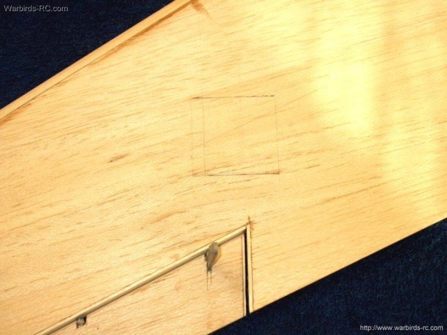
The box is cut with a sharp hobby knife.
Note it is wide enough so that there is 1/4" of space on the
front and back for door mounts | |
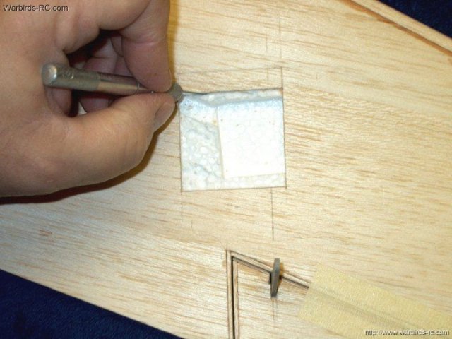
Once the balsa is removed, cut away the
foam | |
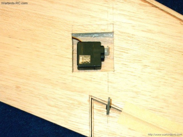
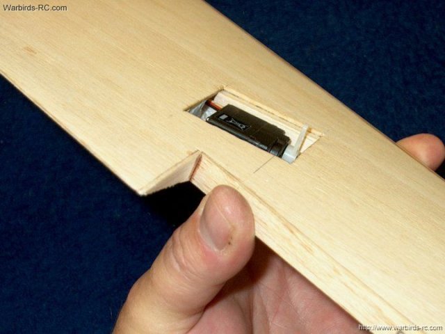
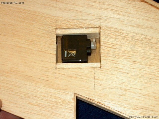
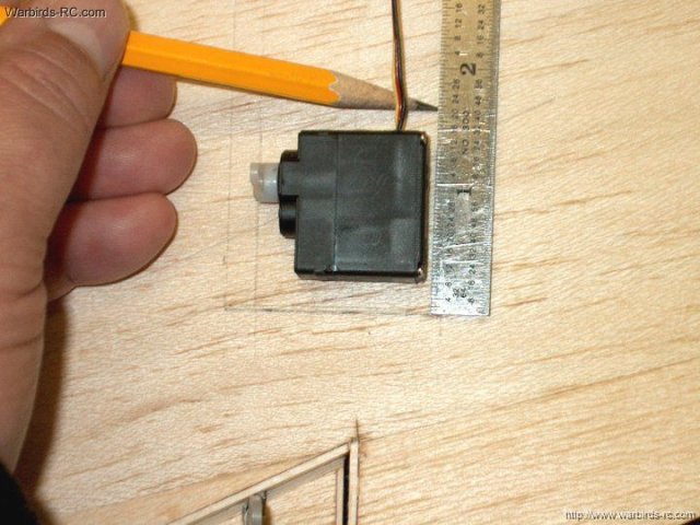
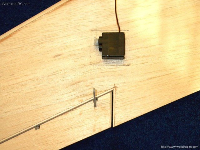
Photo shows the approximate position of
the servo | |
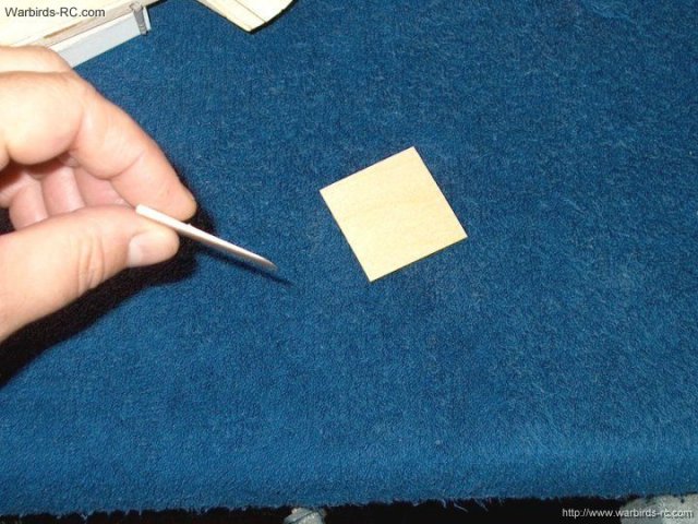
A square piece of 1/8" balsa sheet is
beveled to a wedge so the servo will sit level in the tray
area. The thicker part goes forward
| |
Epoxy is used to glue the wedge shaped
piece in place | |
Tray bottom wedge fitted with the thick
side toward the wing front | |
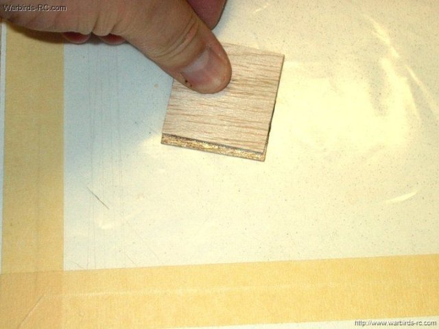
A 1/32" thick piece of ply is cut as a
bottom plate and soaked on one side with thin CA glue
| |
Once the glue dries, sand the surface to a
plastic feel | |
Epoxy is applied to the wedge top and the
ply surface that was not covered in CA
| |
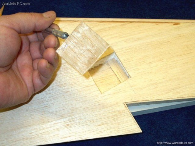
The ply plate was installed, smooth CA
side up and the first wall piece was cut from 1/4" thick
balsa | |
The notch allows the wire to pass into the
wing run | |
1/16" balsa is used on the sides to box in
the servo area | |
All four pieces cut and ready to epoxy in
place | |
Now is a good time to cut a second set for
the other wing. Lay each piece over their corresponding piece
of scrap balsa and cut them to shape. Cut a bit oversized so
you can sand to a good fit later | |
Glue the four pieces in place using five
minute epoxy | |
The hole for the servo leads is shown as
accessible | |
The servo fits just a bit loose from top
to bottom in the pic and is centered side to side
| |
A piece of 1/64" ply is cut to fit as a
cover | |
A piece of 1/16" balsa is cut and laid
over the ply cover | |
With both pieces installed, the balsa
piece on top is sanded flush | |
Laminate the balsa and ply pieces together
with epoxy | |
Next, the cover is installed normally with
the ply on top and lightly sanded | |
Ply and balsa servo cover and tray area
completed | |
The second Aileron servo is centered using
a receiver or device | |
A centerline is drawn on the second wing
for horn alignment | |
The top of the servo well is drawn 1/4"
past the centerline | |
As with the first wing, a rule is used to
draw the aileron wire runs | |
Bottom of the servo well is marked 1"
above the Aileron tip area | |
Another mark is made 1 1/2" away from the
horn center line | |
A line is drawn parallel to the others at
the mark | |
The bottom is kept square and drawn at the
1" mark | |
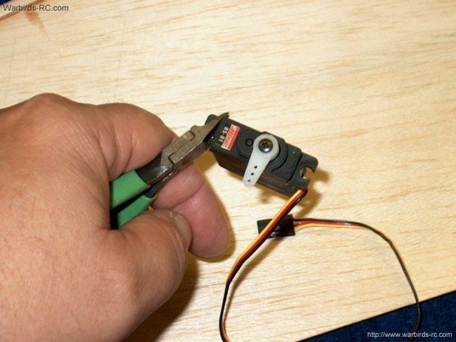
The ears on the servo are removed
| |
A mark is made so the servo has a 1/4"
space on both sides | |
A line is drawn to box in the servo
well | |
Servo area ready to cut
| |
Servo shows its position realative to the
well | |
A sharp knife is used to remove the balsa
and cut the foam | |
A ruler is used as a scraper to remove the
foam | |
Foam is removed from the well area
| |
A piece of 1/8" thick balsa is sanded to
slope like a wedge | |
Balsa wedge plate is epoxied in place with
the thick part forward. This will keep the servo level in the
well | |
The foam area for the Aileron servo wire
run is enlarged | |
A 1/32" piece of ply has thin CA applied
to one side, then sanded to a plastic feel once dry
| |
Epoxy is applied to ply side that doesn't
have CA , then the plate is installed in the bottom as a servo
mount surface | |
Move the plate around to make sure it is
settled and centered in position before the epoxy sets
| |
The four pieces for the walls that were
previously cut are final cut and sanded to fit the well
| |
The thin sides are epoxied in first, then
the top and bottom thick pieces are epoxied in place
| |
Servo well is shown framed in
| |
A thin 1/64" ply plate is cut to sized and
installed, then a balsa piece in installed.
| |
The balsa is sanded to thickness for the
wing surface | |
The balsa and ply are laminated together
with epoxy | |
Servo cover shown in final position with
ply on top | |
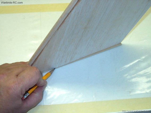
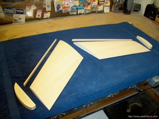
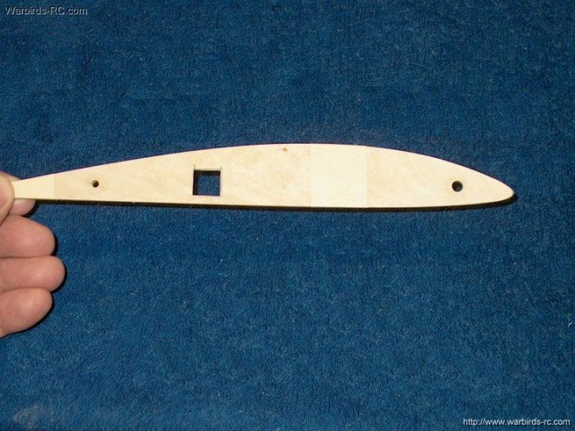
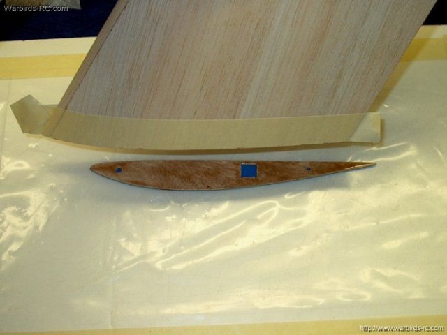
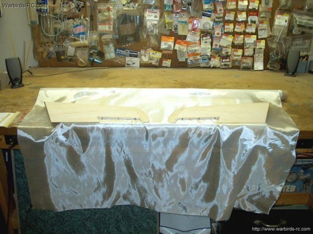
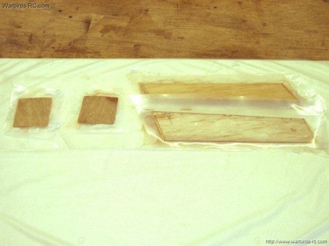
The wing root is placed over one of the
1/16" x 9 x 1 1/2" ply pieces and the shape of the root is
drawn on the ply | |
Ply plate shown with wing root chord shape
transfered | |
The root piece is oversize cut using a
saw | |
The second wing root piece is drawn and
cut to shape | |
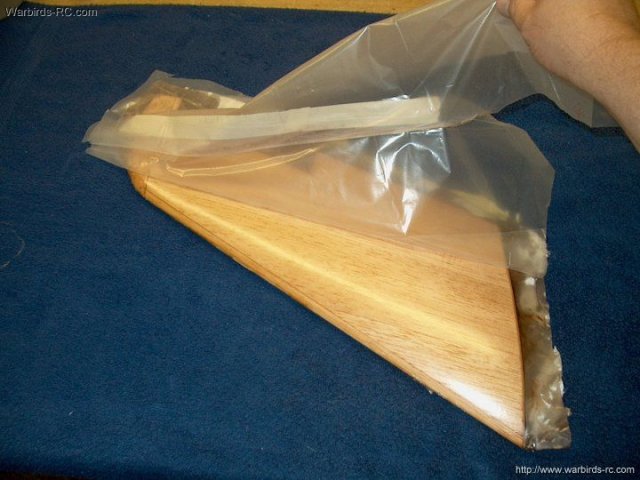
Plates are marked Left and Right, then one
is sanded even to and taped flush to the bottom of the
wing | |
With the wing root held flush by the tape,
sand the top of the root level to the wing
| |
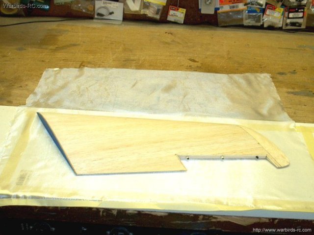
Wing root shown sanded to shape top, front
and rear | |
The second wing root is taped and sanded
the same way | |
Once the middle of the root is sanded,
masking can hold it in place at the top while you shape the
leading edge | |
Two marks are made at the location of the
Aileron servo wire run | |
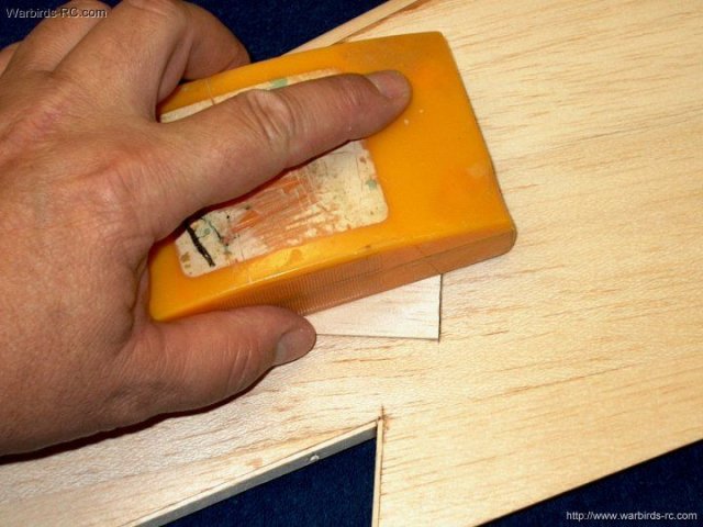
Extra foam is removed from the wing for
easier running of the wire | |
Hole has been angled and opened for easier
wire exit | |
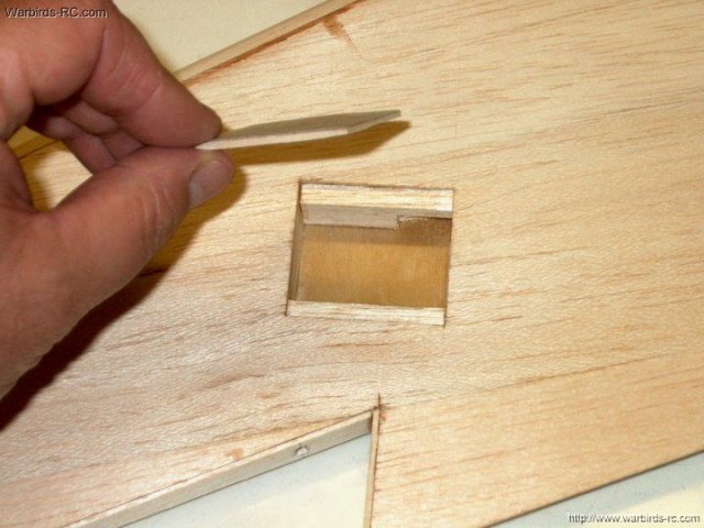
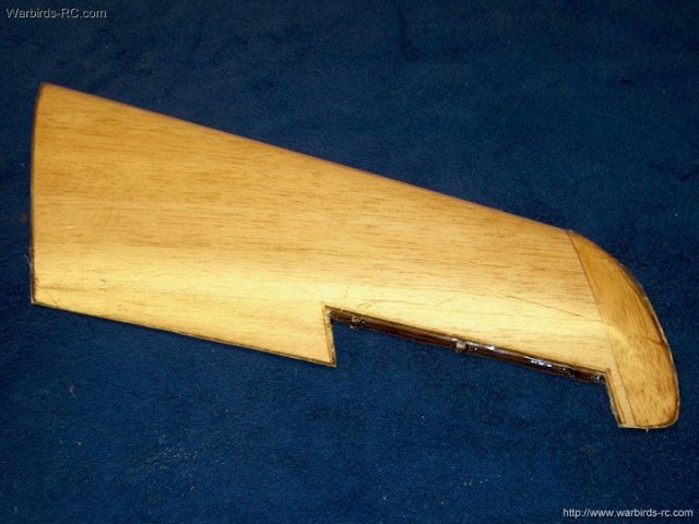
An opening is drawn on the root for the
servo wire exit | |
A heavy flat knife easily cuts the square
opening out | |
Aileron wire hole shown cut from the root
piece | |
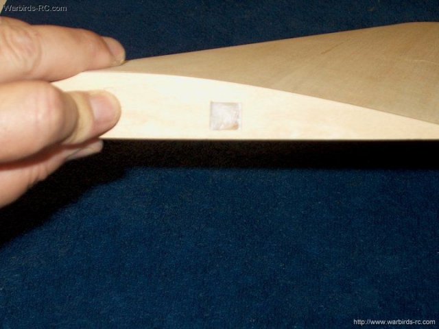
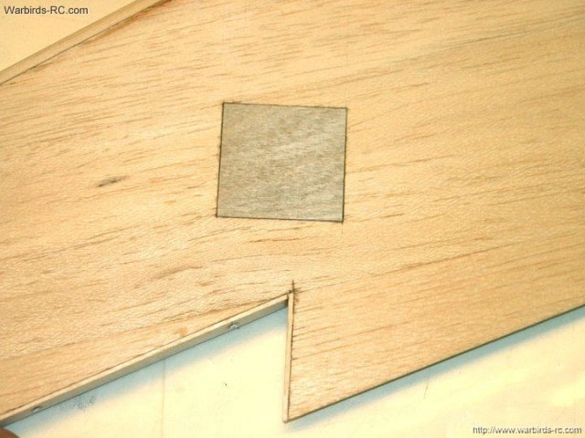
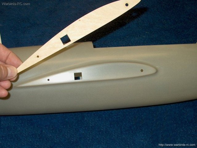
Photo shows how it fits over the hole in
the wing | |
The second wing root is marked for the
Aileron wire hole | |
Hole is cut using a flat knife
| |
The fuselage wire exit is once again
enlarged | |
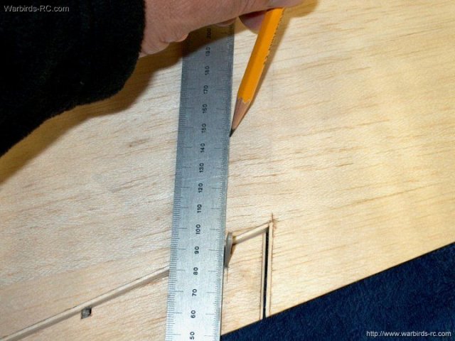
A mark is made 2 1/4" from the rear of the
ply root | |
Another mark is measured 6 1/8" from the
first mark | |
A center mark is made at the rear
location | |
A center mark is made at the front
location | |
A punch is used to mark the drill spots,
then a 1/16" bit is used to start each hole
| |
The two roots are centered over eachother
and taped together, then the rear hole is drilled with a 1/8"
drill bit | |
The forward mark is drilled with a 3/16"
drill bit | |
Wing roots showing drilled areas
| |
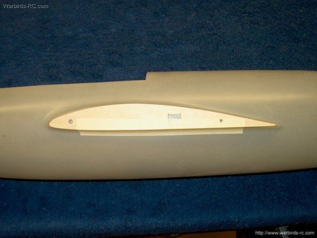
The root is taped flush to the bottom of
the wing root on the Fuselage | |
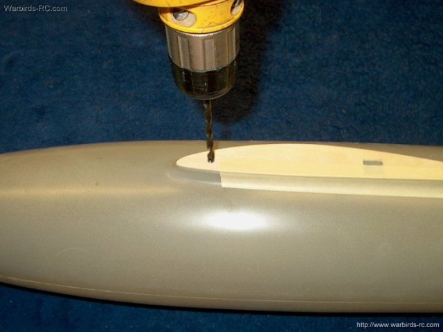
The 3/16" forward drill hole is transfered
to the Fuselage | |
The rear 1/8" hole is transfered to the
fuselage. Make sure the wing root remains flush with the
bottom as this will insure true wing incidence later during
the assembly | |
A marker is used to mark the location of
the Aileron wire run | |
The hole for the Aileron wire is cut with
a sharp hobby knife | |
A file is used to square up the wire
hole | |
Wing root preparation shown completed on
one side | |
The second wing root drill holes are
transfered, keeping the root flush to the bottom of the
fuselage as shown | |
Second wing root is cut out for the
Aileron wire run and shown as finished
| |
Make sure both wing roots are flush with
no bowing | |
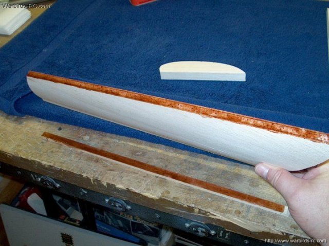
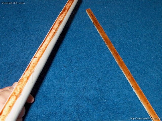
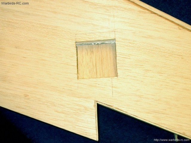
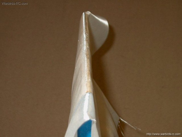
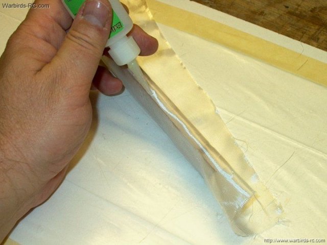
The side of the spar that is not glued to
the wing is covered with masking to keep it free of
epoxy | |
Spar surface shown sealed with masking
tape | |
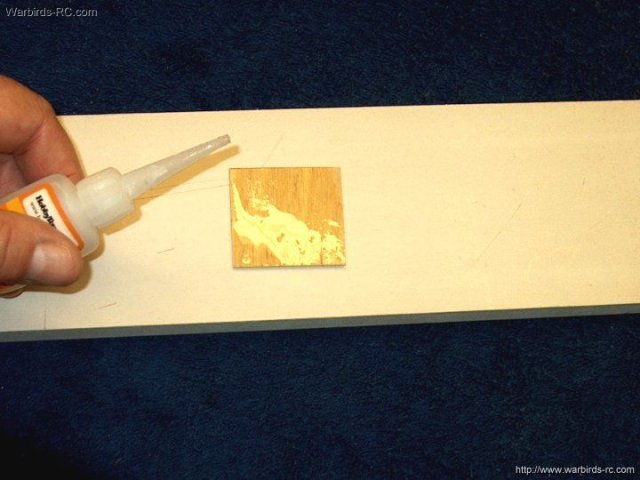
15-30 minute epoxy is applied to the other
side of the spar | |
Place masking tape on the second spar and
apply epoxy | |
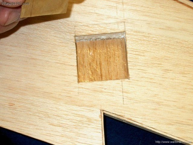
The wing root edge top and bottom has
masking tape applied so epoxy will not drip on the surface
edges | |
Epoxy is applied to the wing root
| |
Wing has been prepared
| |
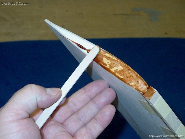
Place the wing root on the spar and press
to squeeze out excess epoxy | |
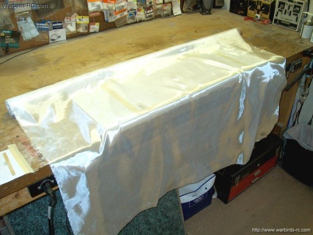
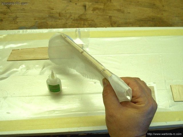
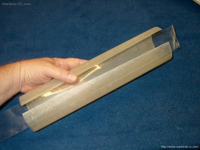
3/4 oz fiberglass cloth will be used to
glass the wings | |
A piece is cut wide enough for both
wings | |
A section of cloth is cut and fit for a
single wing | |
The wing is carefuly dusted of any
particles | |
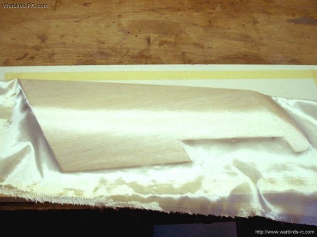
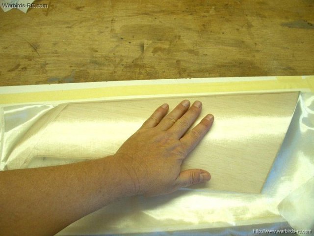
The cloth is folded over the wing and
centered even on both sides | |
Excess cloth is trimmed prior to
glassing | |
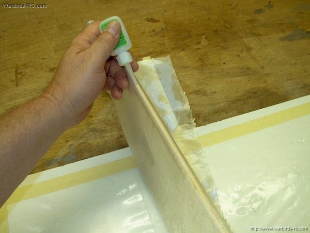
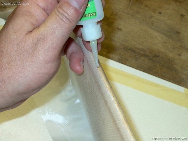
The cloth is centered over the wing
leading edge, then a thin line of medium CA is applied all the
way down the leading edge | |
The CA is pressed through the cloth to the
wing and spread down the leading edge
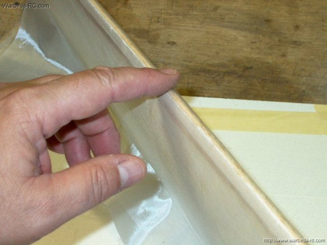
| |
Leading edge is secured to the cloth. This
will allow you to pull and stretch out the cloth on both sides
for a nice fit | |
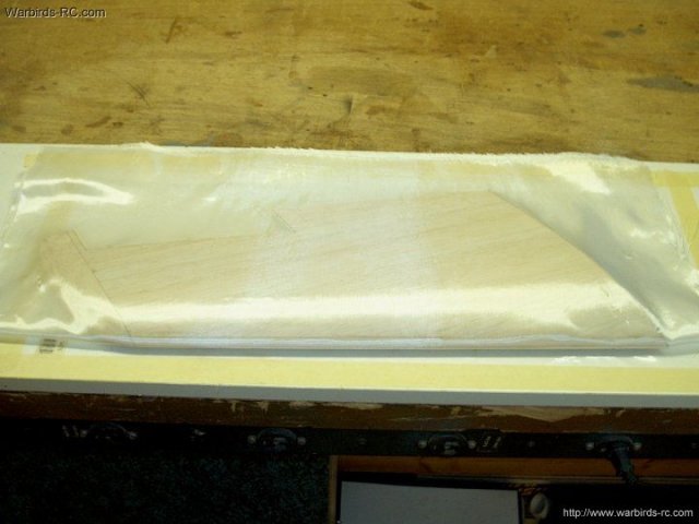
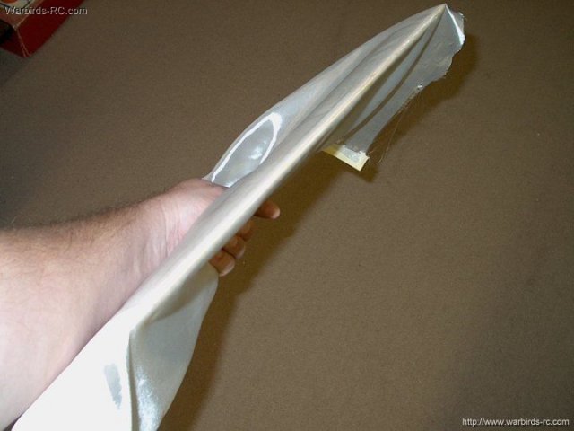
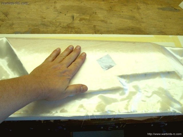
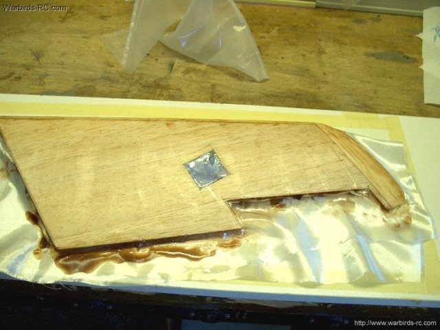
The wing is laid on a piece of plastic and
the cloth is formed by hand to the surface contour
| |
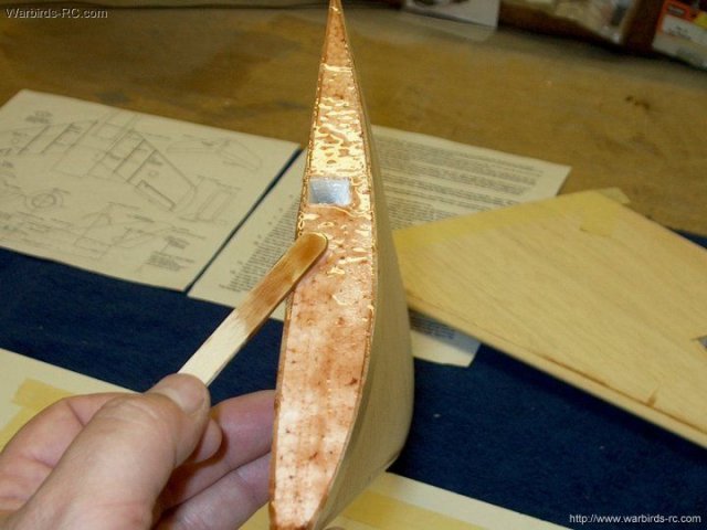
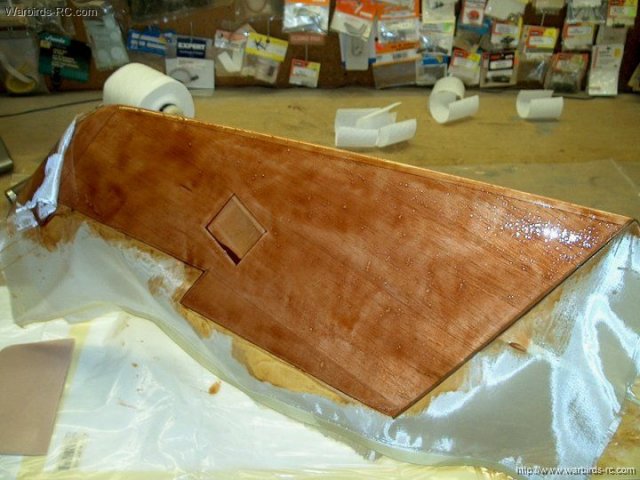
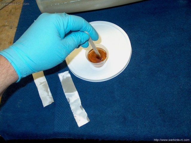
West Systems Epoxy was used for the
glassing process. Be sure to mix the epoxy thoroughly
| |
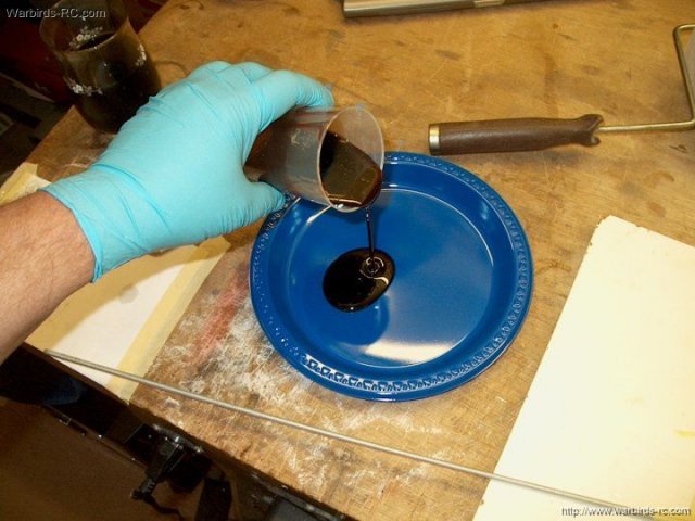
The epoxy is poured into a plastic
disposable food plate so it doesn't cure too quickly
| |
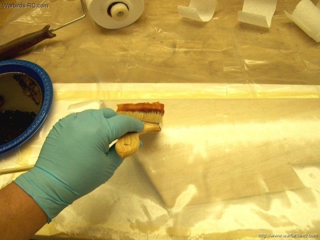
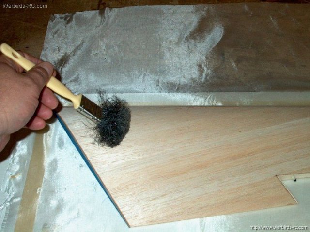
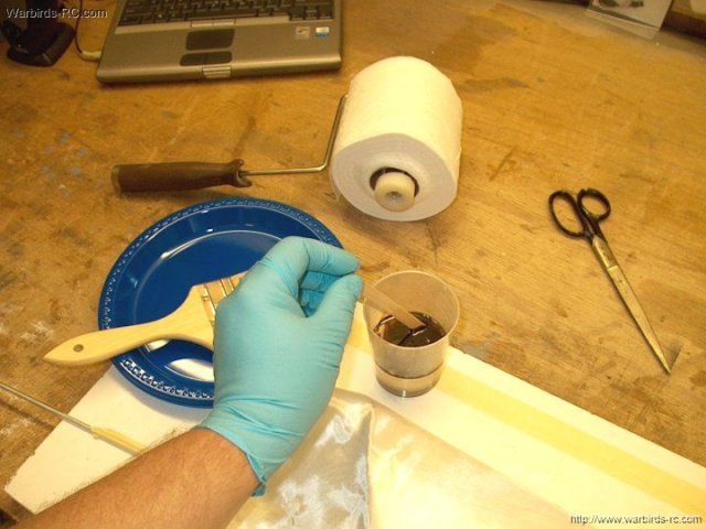
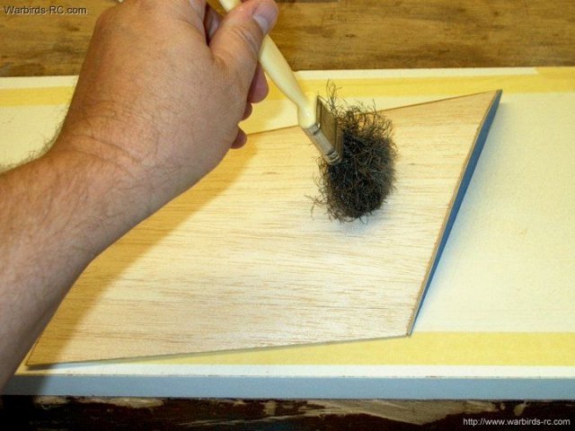
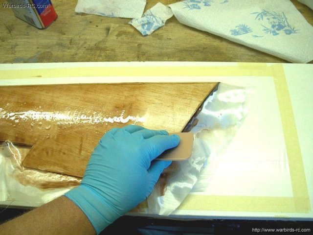
A brush is used to apply the epoxy,
starting with the leading edge | |
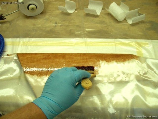
Work your way across, then back and across
again and be sure to wet down the cloth well with resin
| |
Epoxy applied to one side of the
wing | |
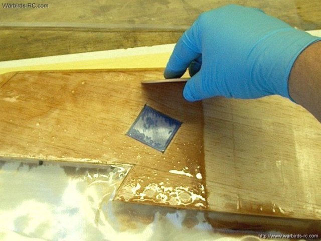
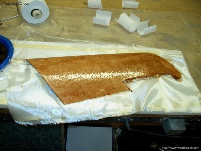
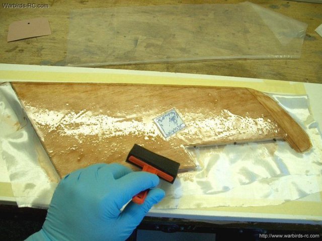
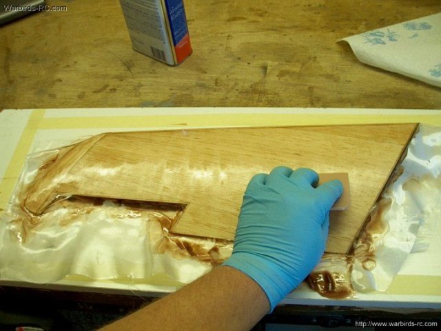
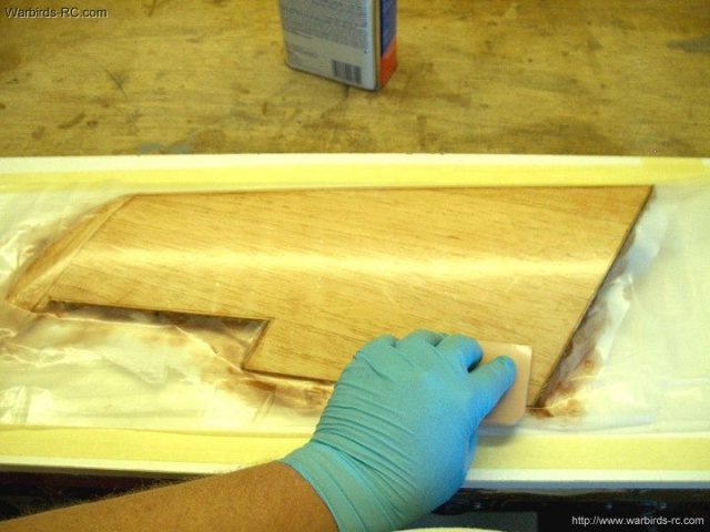
A putty squegee is used to remove excess
resin, then the wing top is covered with plastic
| |
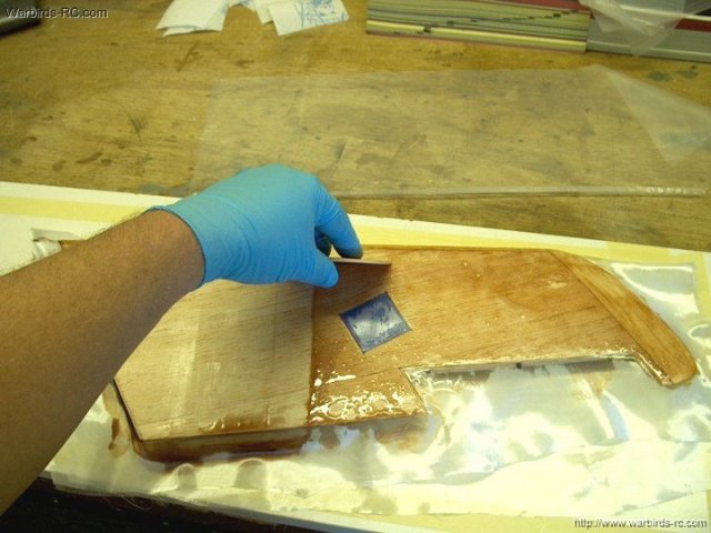
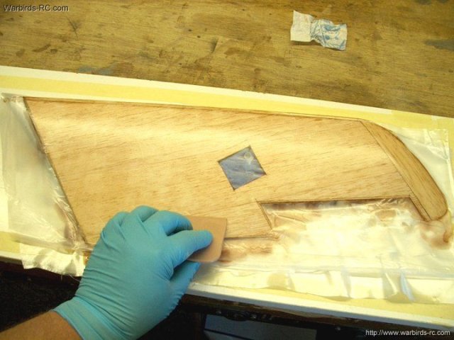
The bottom of the wing is wetted out
before the resin begins to cure. Watch your working time.
Squegee off the excess and cover with a plastic sheet
| |
The second wing is prepared to
glass | |
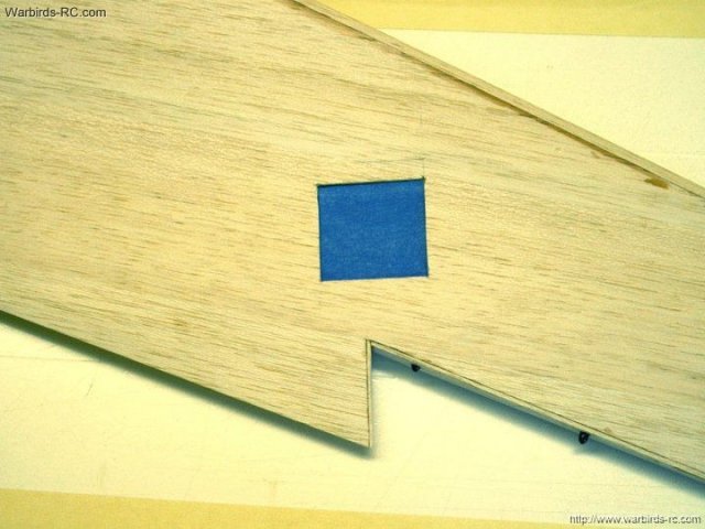
The hole for the Aileron servo is plugged
with a double thick piece of tape square
| |
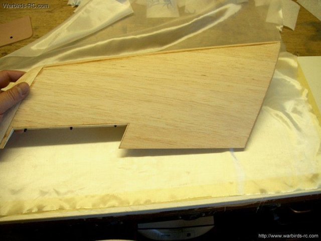
The wing is placed on the cloth and
centered | |
The cloth is formed with your hand to
follow the wing contour | |
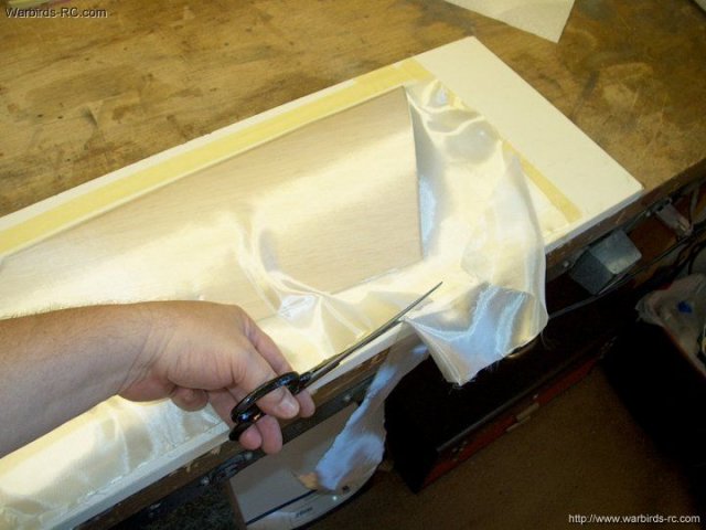
Excess cloth is cut away
| |
Medium CA is applied to the leading edge
of the second wing | |
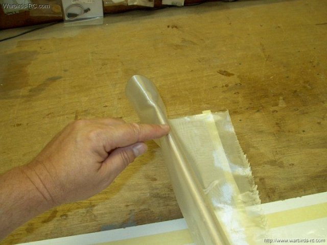
The CA is spread across the entire leading
edge | |
CA has set and anchored the cloth at the
leading edge | |
The wing is placed over plastic sheet then
contoured once again | |
Mix up a fresh batch of epoxy resin and
apply it to one side | |
Once again, the excess resin is removed
from the wing | |
Excess resin has been removed
| |
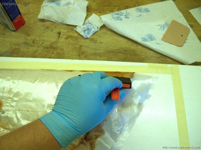
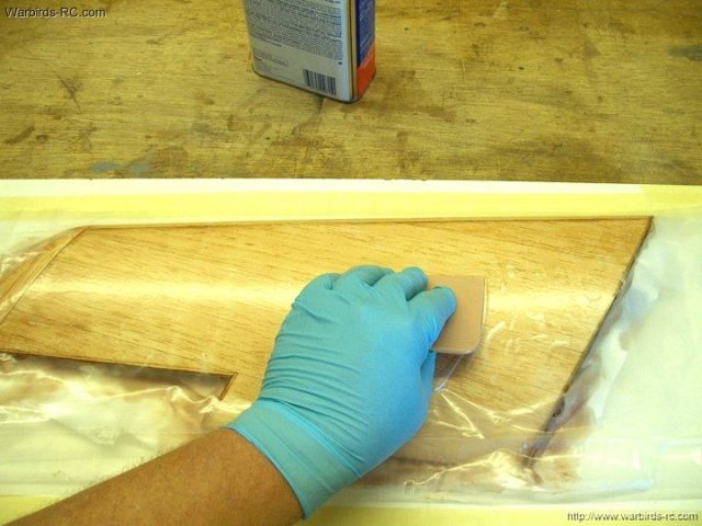
A 3 mil plastic sheet is laid over the
wing and pressed down | |
The wing is flipped over and resin is
applied to the other side | |
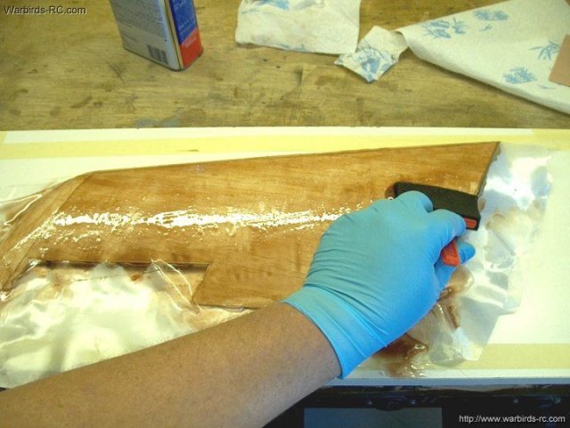
Be sure to wet out the cloth well with
resin. A disposable brush works well
| |
Once again, the excess resin is removed
from the wing | |
Continue with the spreader until all
excess resin is removed | |
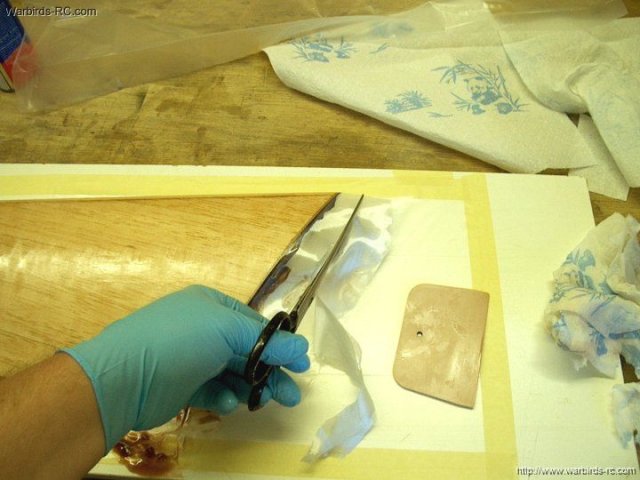
Excess cloth is removed prior to
covering | |
A plastic sheet is placed over the wing
and pressed down with the spreader. Be sure to remove all air
bubbles | |
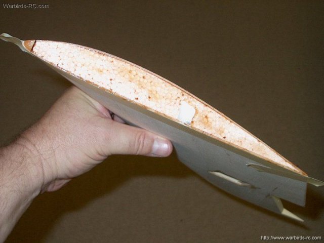
Wing is glassed and sealed
| |
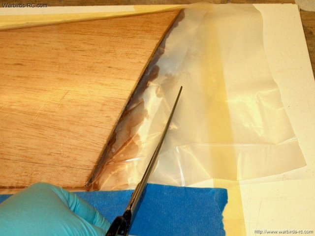
Excess plastic is removed
| |
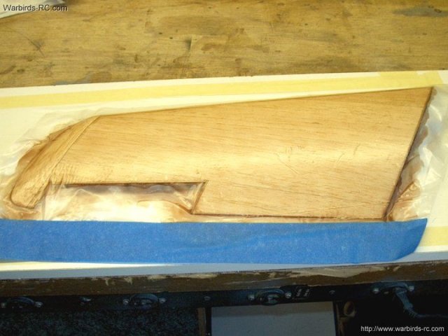
Wing fiberglassing completed
| |
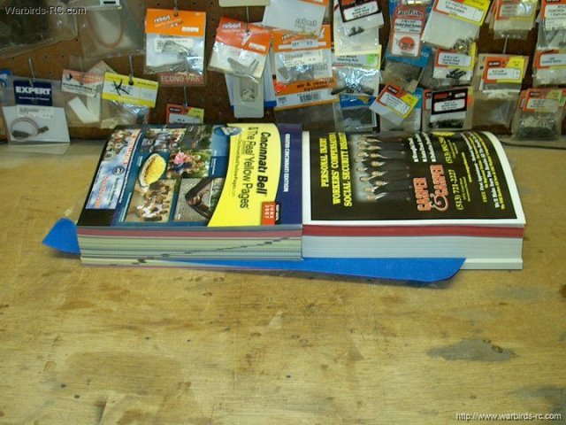
The wing is placed between a couple phone
books and left until it sets | |
Wing fiberglassing has set and is shown
below | |
The Ailerons and covers also need to be
glassed. Cloth is cut to fit each piece
| |
Medium CA is used across the entire
forward surface on both Ailerons | |
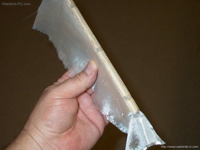
Photo shows cloth glassed with CA to the
front of the Aileron | |
The second Aileron is prepared in the same
way | |
The cloth is folded over and resin is
applied to both sides of the Ailerons and the ply side of the
servo covers, then the excess is removed and all parts are
covered in plastic and placed in a phone book to keep them
flat | |
Once the epoxy has set, remove the plastic
covers from each wing | |
The outer edges are rough cut with a hobby
saw and knife | |
The servo hatch is removed from the
plastic | |
Both hatches are rough cut and the excess
cloth is removed | |
Cut off the excess cloth from each
Aileron. Fine sand the Wings, Ailerons and Hatches
| |
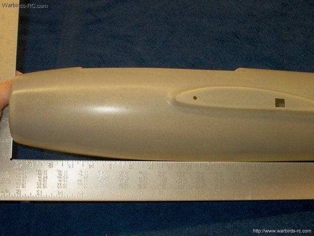
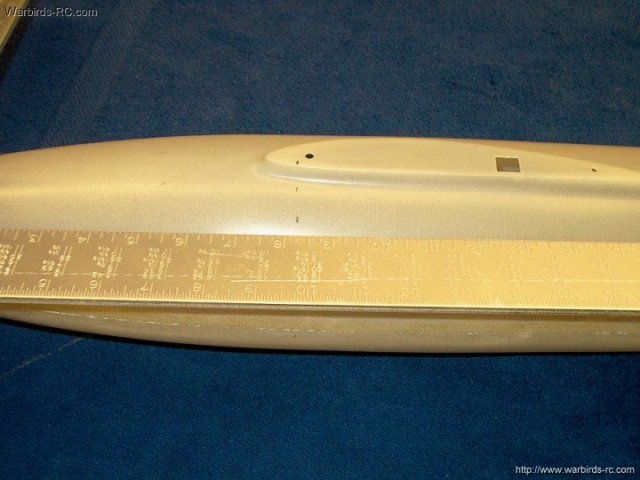
Fuselage assembly begins by sanding the
seam with 400 grit sandpaper | |
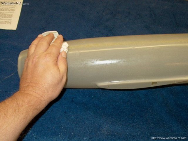
The sanded area is wiped down with a damp
cloth | |
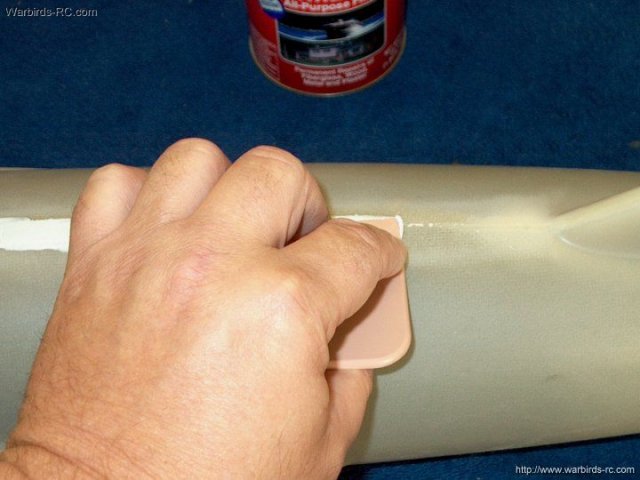
A good body filler was used to fill the
seam | |
Seam filled on the top and bottom of the
fuselage and left to set | |
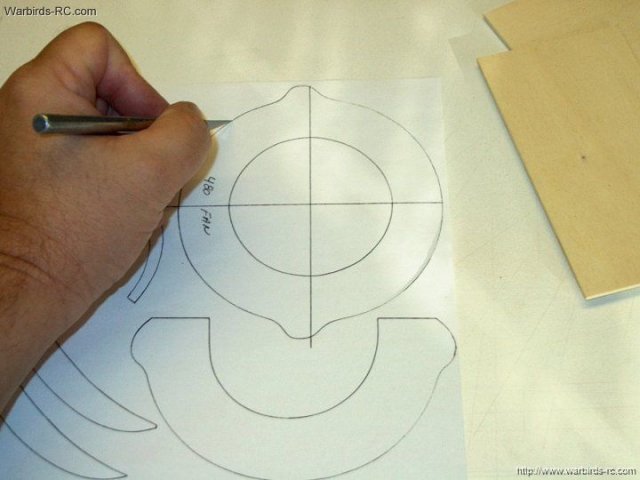
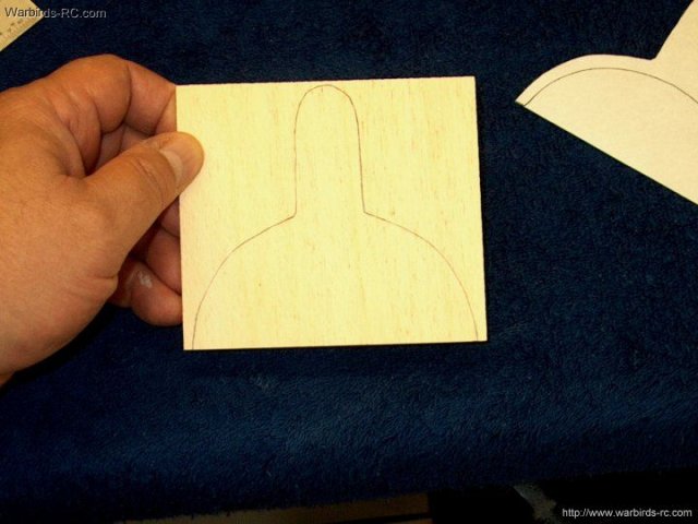
Two patterns for the main former are
supplied, one for the Wemotec HW 609 fan and one for the
Wemotec Minifan 480. Cut out the pattern for the fan you will
use | |
The minifan is used to draw a more
accurate center on the template | |
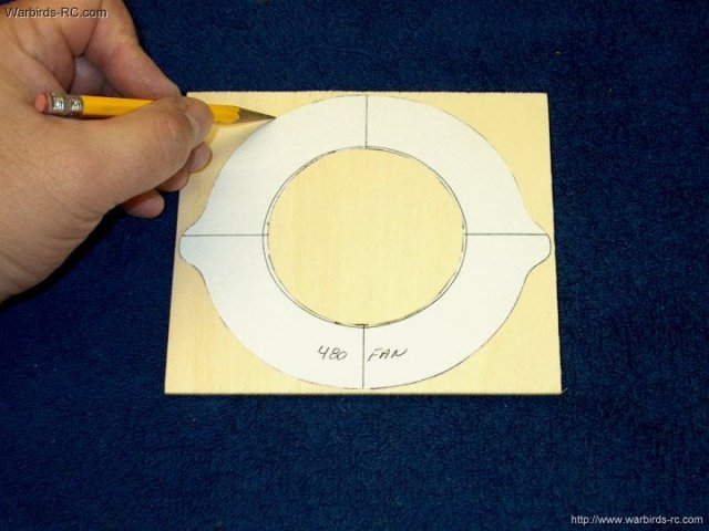
The main former template is transfered to
its repective plywood sheet | |
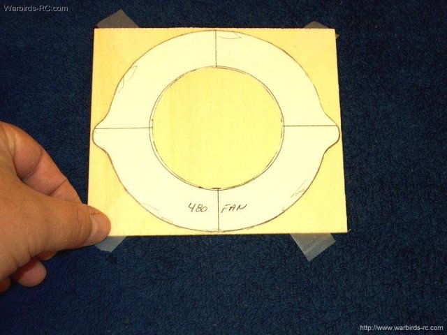
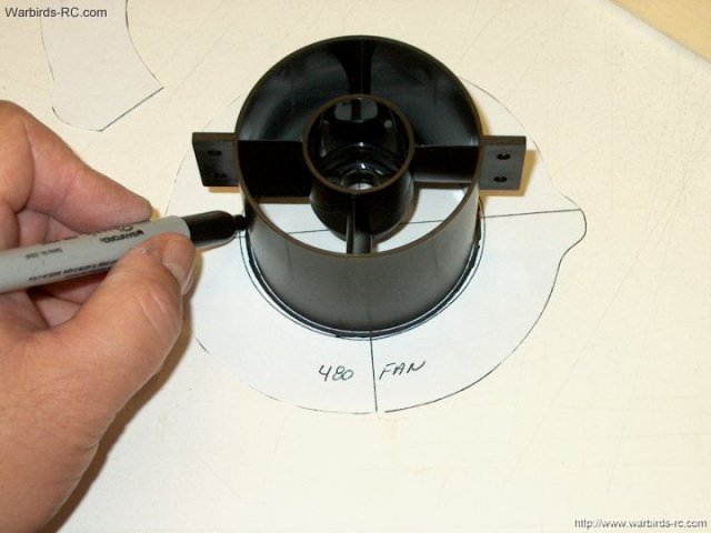
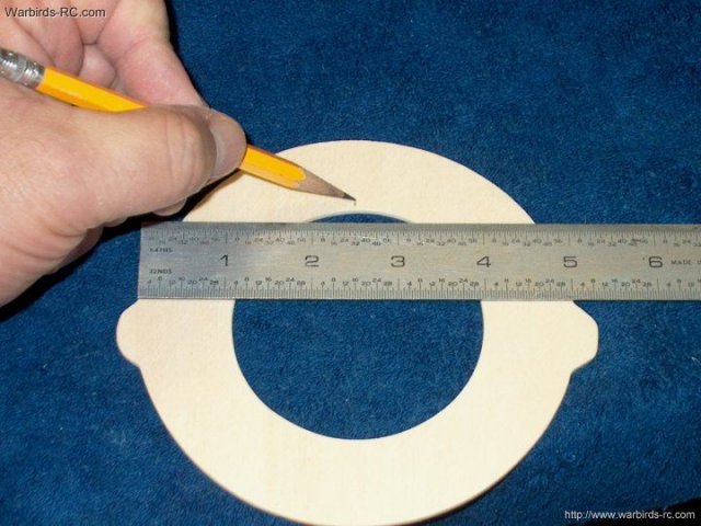
The sheet for the center former is traced
on the outside, then taped in place
| |
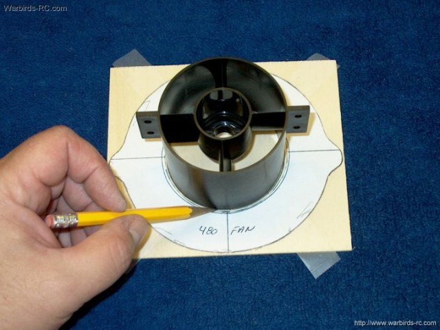
A clean circle is made using the fan
housing | |
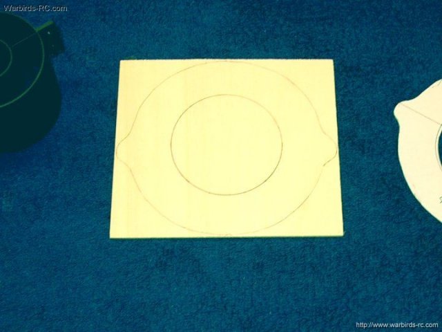
Center Former is ready to cut
| |
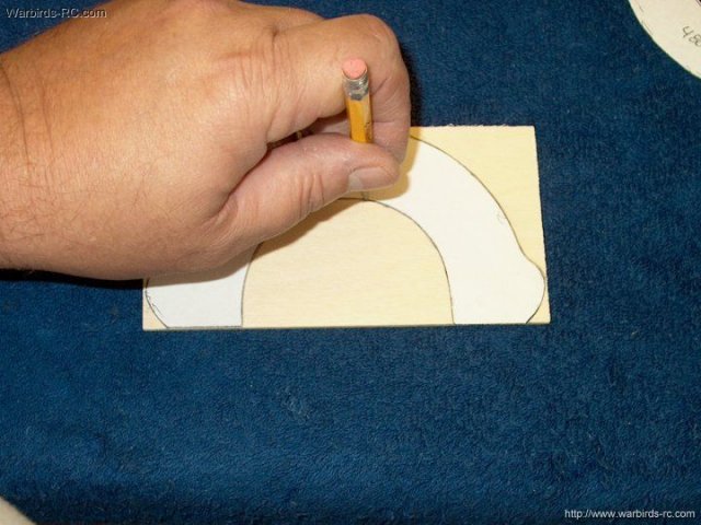
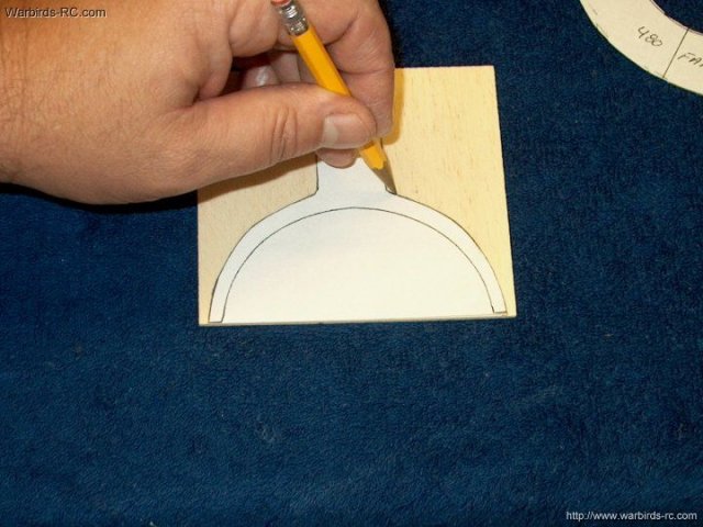
The front former is traced
| |
The front former is ready to cut
| |
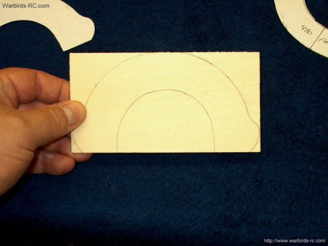
The rear former is traced
| |
The rear former is ready to cut
| |
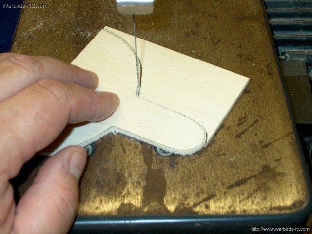
A scroll saw or coping saw is used to cut
out each former. Cut it so you have some extra to sand to
exact shape | |
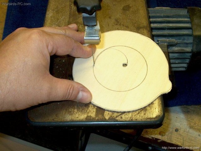
The center of the main former is shown
drilled and being cut | |
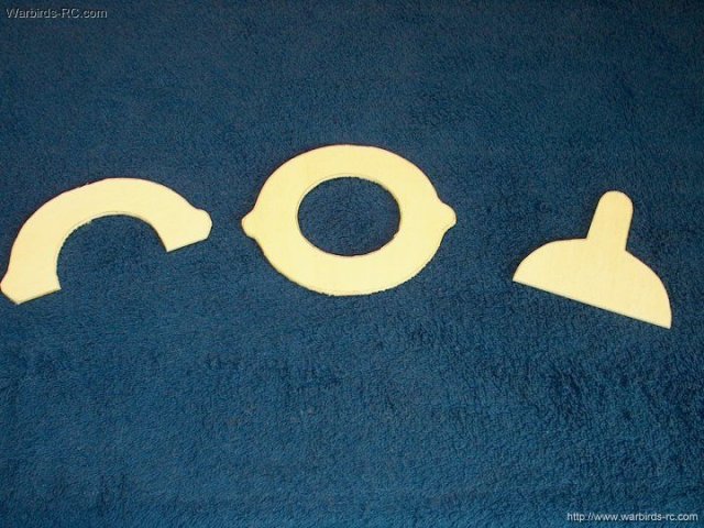
All three formers have been rough cut on
the scroll saw | |
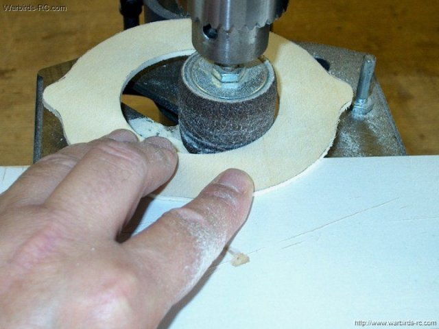
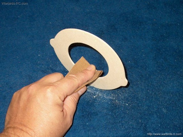
A drum sander on a drill press made
sanding the inside and outside edges much easier. You can also
sand by hand | |
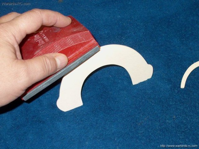
The formers are fine sanded for a good fit
| |
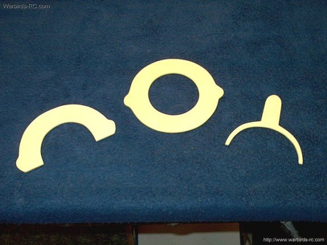
Formers shown ready to install
| |
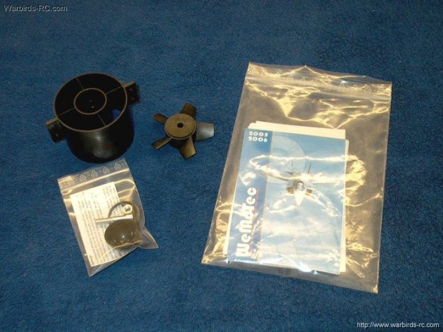
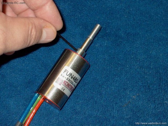
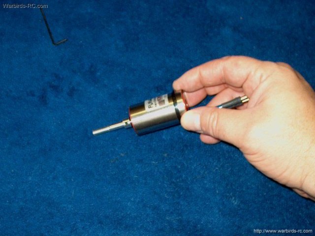
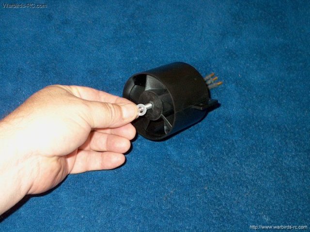
The model will be powered by a Wemotec
Minifan 480 and a Kontronik 480-33 Brushless Motor using a 4S
lipo battery | |
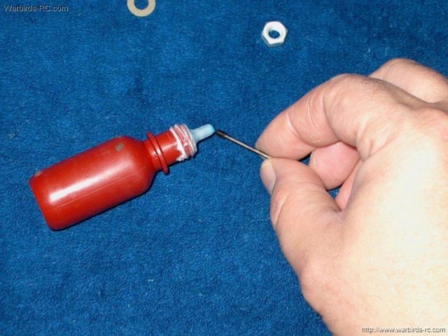
Loktite is applied to the shaft adapter
set screws | |
Set screws are installed in the shaft
adapter but not tightened | |
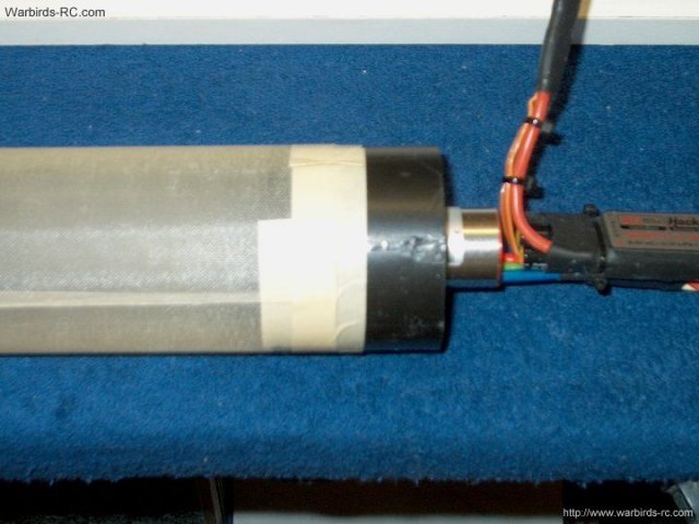
The motor is temporarily installed to set
adapter spacing | |

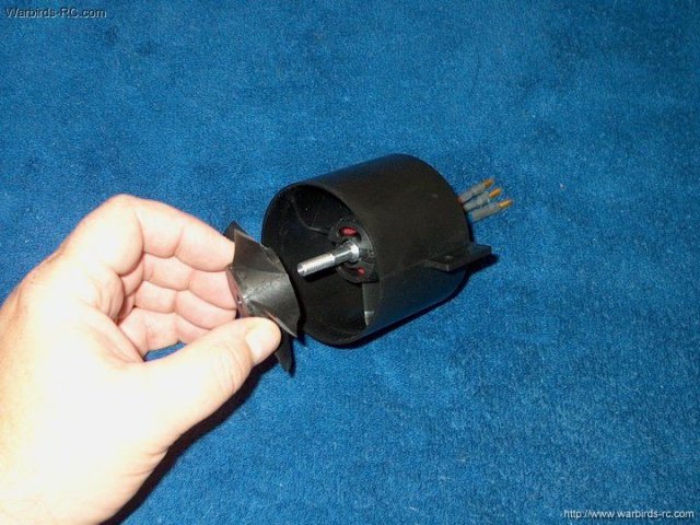
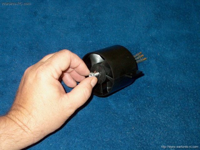
The rotor is placed on the shaft and the
shaft is pulled to bottom out and pull away the rotor from the
rear of the housing so it does not rub
| |
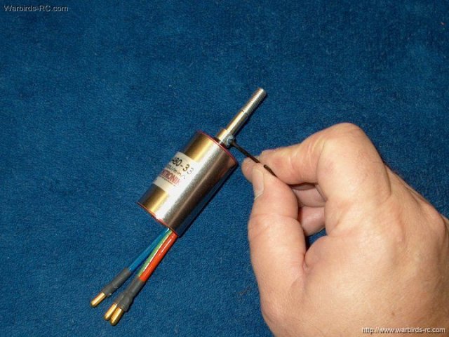
The motor is carefully removed and the set
screws are tightened with proper spacing set between the
bottom of the adapter and the motor front plate. Clean up all
excess Loktite with a Q-tip | |
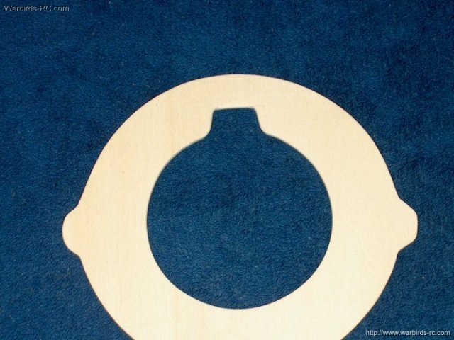
The motor ring is place on the rear so it
will keep the motor centered. Some sanding on the inside of
the ring may be necessary for a good fit and a Dremel with a
drum sander works well | |
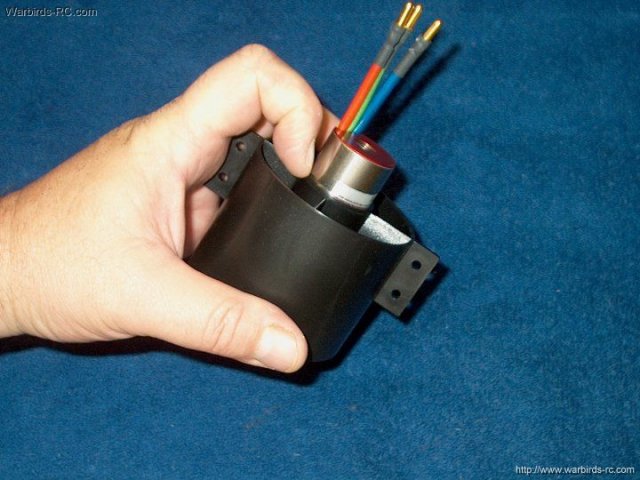
The motor is installed and the ring is
pressed in so it recesses flush in the back of the
housing | |
Install two 3mm x 6mm long bolts but do
not use Loktite on the bolts as it will attack and eat away at
the housing! Use either green Loktite or apply Blue locktite
only to the motor threads with a toothpick and wipe of all
excess prior to installing the motor in the fan
| |
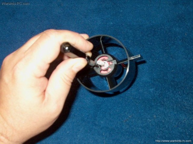
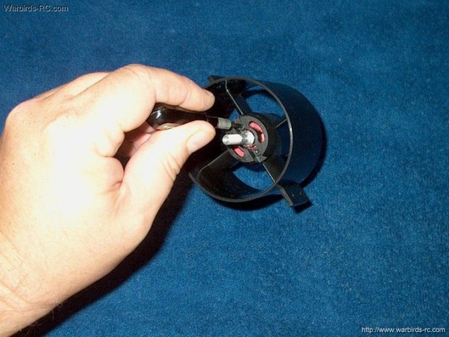
Once the motor is tightened, install the
fan rotor. Be sure to balance the rotor per manufacturers
instructions prior to installation | |
Install the fan washer
| |
The aluminum nut is installed next
| |
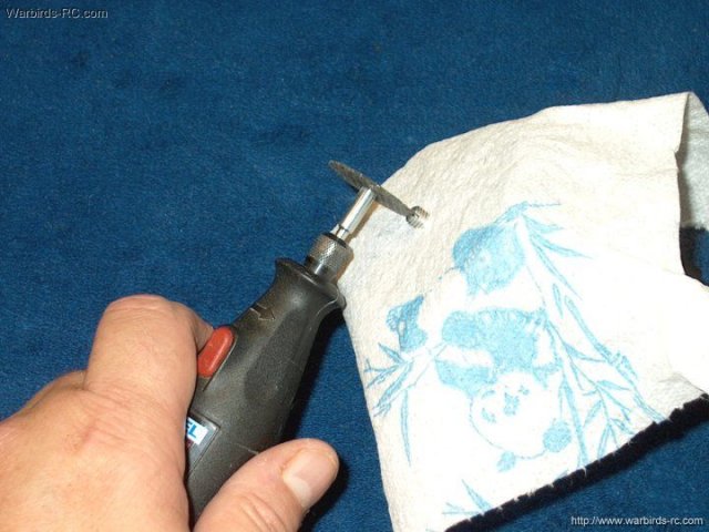
The fan is covered with a paper towel to
protect it from shavings and a Dremel with a cutting wheel is
used to slot the end of the shaft adapter about 1/8"
deep | |
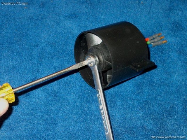
A screwdriver is used in the slot to hold
the shaft while the nut is tightened
| |
The fan hub can be installed and pops in
place with some pressure. You can add some Loktite to the
inside threads at the tip of the shaft adapter before
installing the hub | |
The hub retaining bolt is installed and
held in place with the Loktite you previously added. Do not
overtighten this bolt or the hub could come off during
use! | |
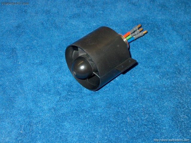
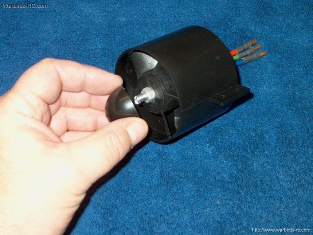
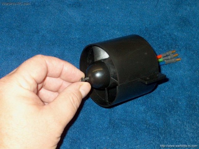
The Wemotec Minifan 480 Fan Assembly is
shown completed | |
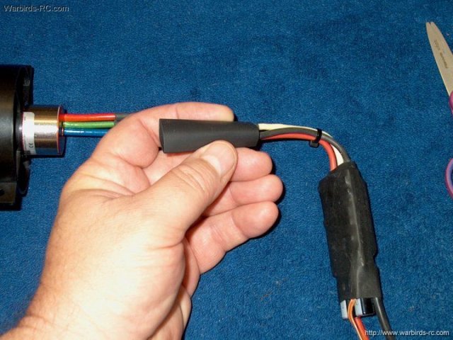
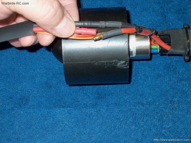
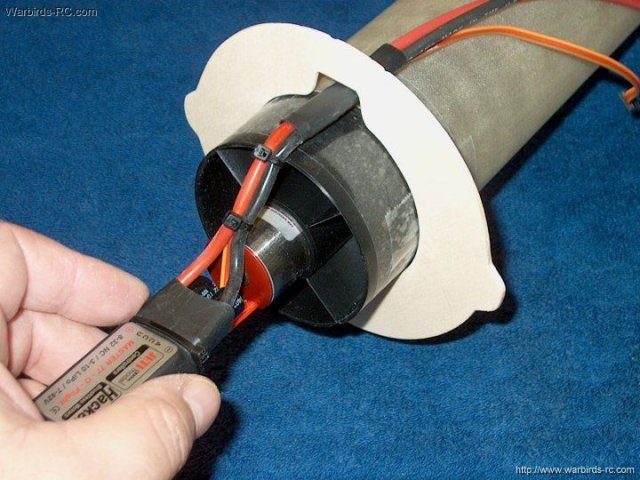
Heat shrink is placed over the ESC wires
and the wires are plugged in to the motor. Hook up a receiver
and test to make sure fan direction is correct. If not, change
any two of the three wires or program your ESC if it has the
reverse feature | |
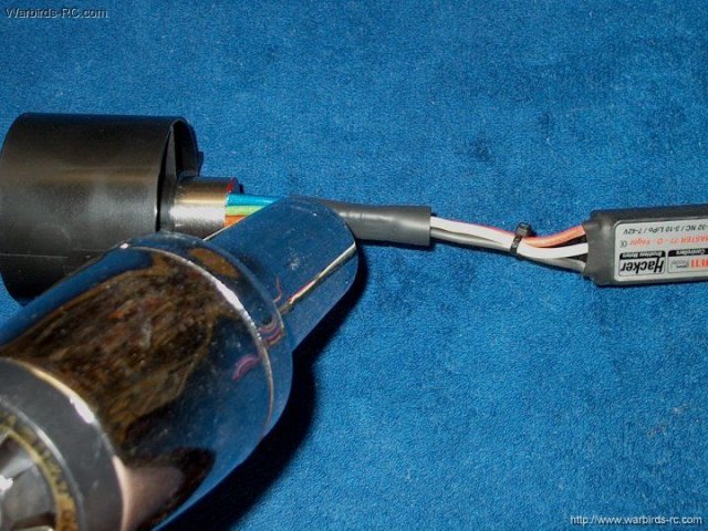
The heatshrink is centered over the wires
to hold the plugs together | |
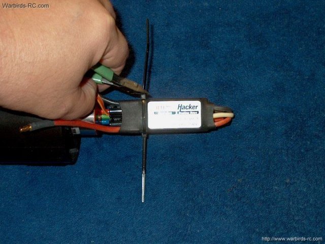
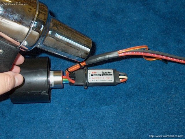
Tie wraps are used to tie the ESC to the
motor wires so it doesn't flop around inside the exhaust
duct | |
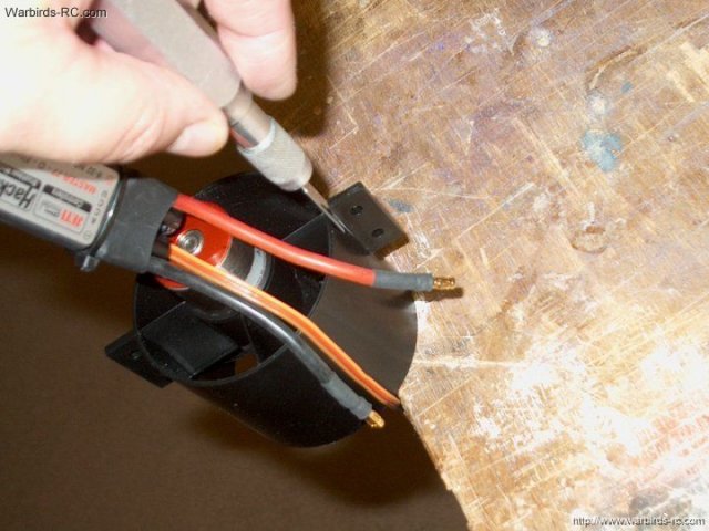
The tabs on the fan will need to be
removed | |
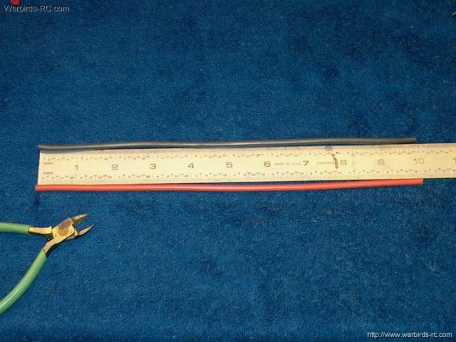
Two wires are cut as shown for the ESC to
battery leads | |
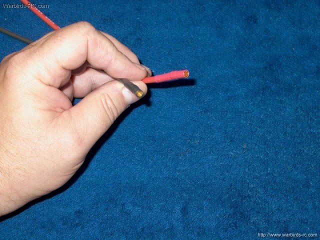
Sockets are soldered to one end of the
wires | |
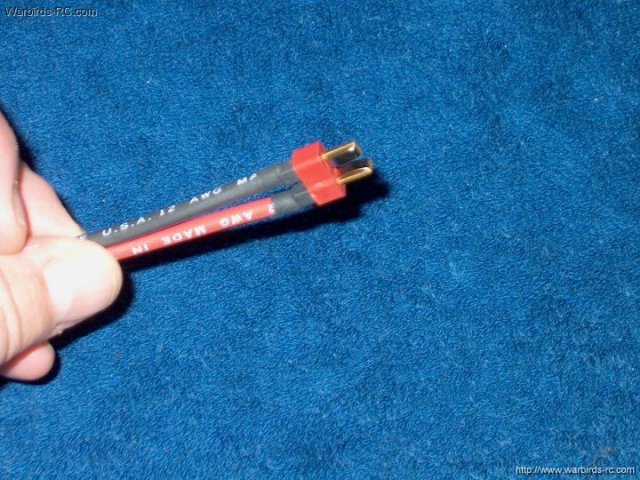
An Ultra Deans male connector is used and
soldered at the battery side | |
The leads are connected to the ESC
| |
Heat shrink is installed to prevent the
wires from unpluging and it keeps the assembly neat and easier
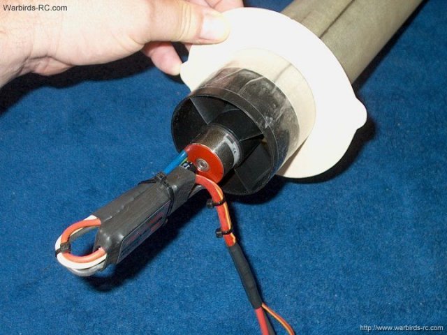
to install | |
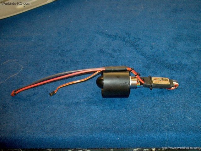
The Minifan Power Plant ready to install
in the fuselage | |
A large square is used to mark the
locations of the formers | |
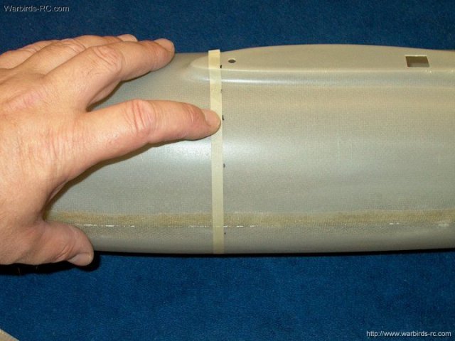
The front former is installed 8 1/4" from
the front of the fuselage. Several marks are made around the
fuselage to help with the alignment of the former
| |
Tape is used to indicate the back of the
former position and to aid with the next step
| |
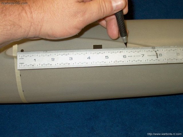
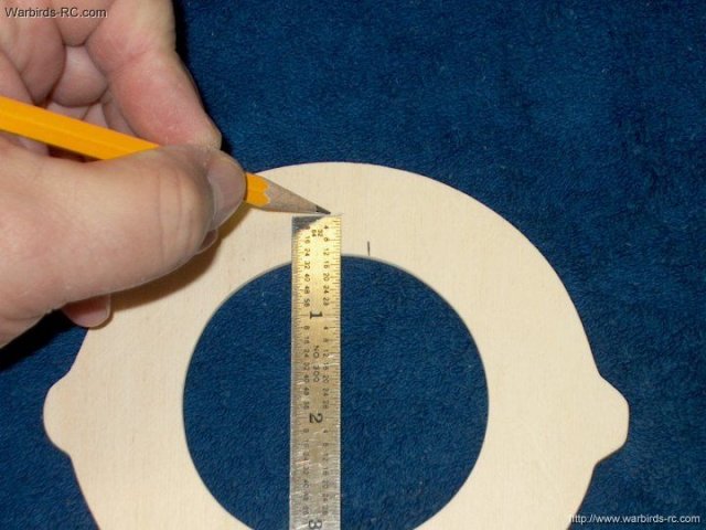
The main center former is located 6 1/8"
from the front former. Make several marks around the entire
fuselage | |
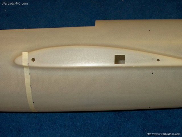
Photo shows locations marked for the rear
of each former | |
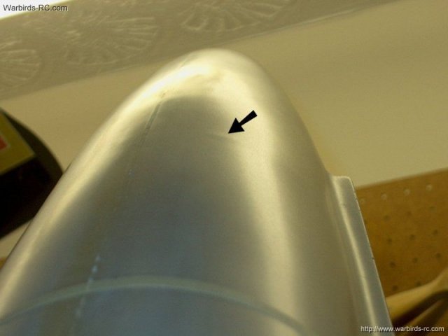
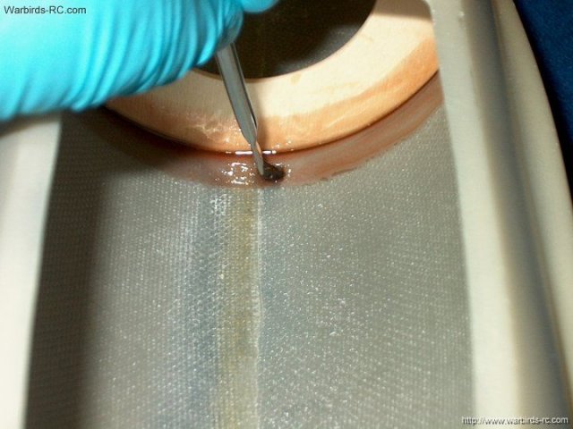
Install the main center former and check
for fit. If you hold it up to a light, you will see bumps in
the fuselage as shown by the arrow below. This is where the
former is oversized, so remove it, sand a little at a time,
reinstall and check again. When the former is shaped
correctly, it will not show on the outside
| |
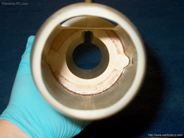
Picture of center main former in place and
fitted | |
Formers are positioned so the rear is on
the marks. This is so you have clearance room to install the
wing dowel clips later | |
Front former shown installed, but the
inside still needs sized | |
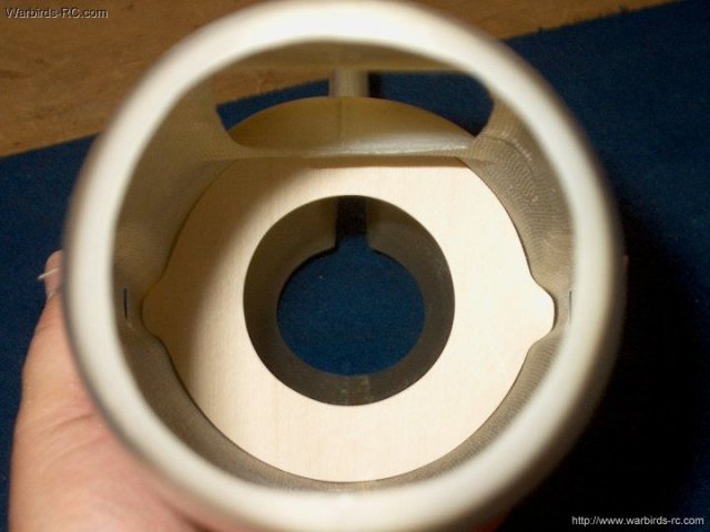
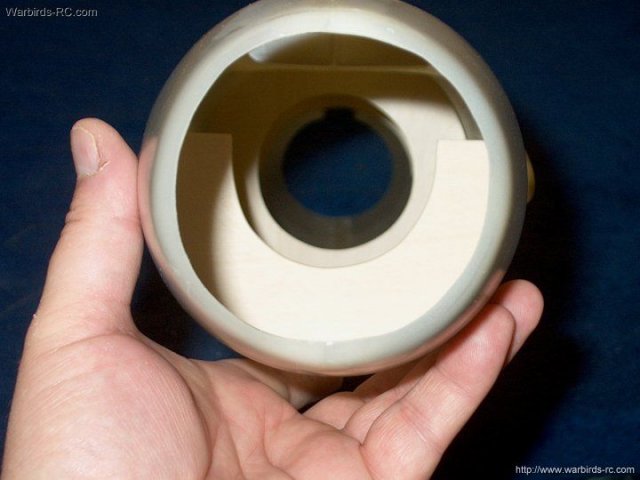
The center former is temporarily fitted on
the fan | |
The fit was too tight, so it needed to be
sanded to a loose fit | |
A center mark is made at the inside
top | |
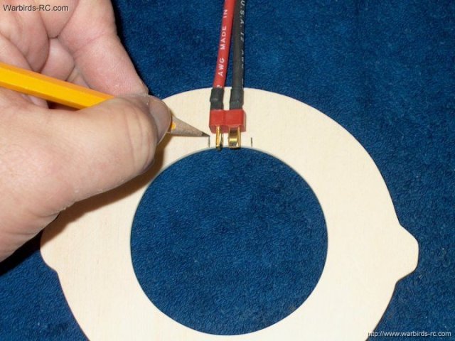
Marks are made evenly from the center and
slightly oversized so the power plug will fit through
| |
The top is marked for clearance
| |
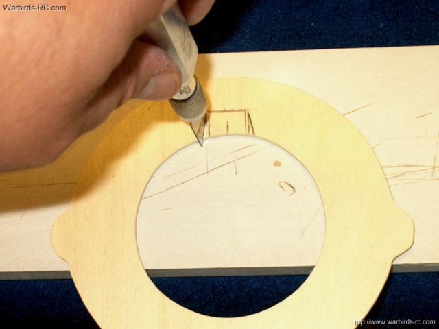
The area is cut to allow clearance for the
power and servo cables | |
The corners are rounded and the former is
ready to install | |
Former is test fit over the fan assembly
and easily clears the duct | |
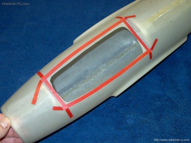
Now is a good time to trim the Cockpit
opening so you won't get cut while working in this area. Start
by outlining the cockpit with 1/4" trim tape with the outside
at the edge of the cockpit area | |
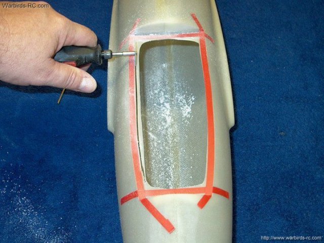
A cutting wheel is used to rough cut the
heavy areas | |
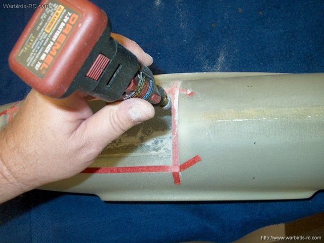
A dremel and 1/2" sanding wheel on low
speed is used to grind the inside edges to the tape. Be
careful to not cut too much | |
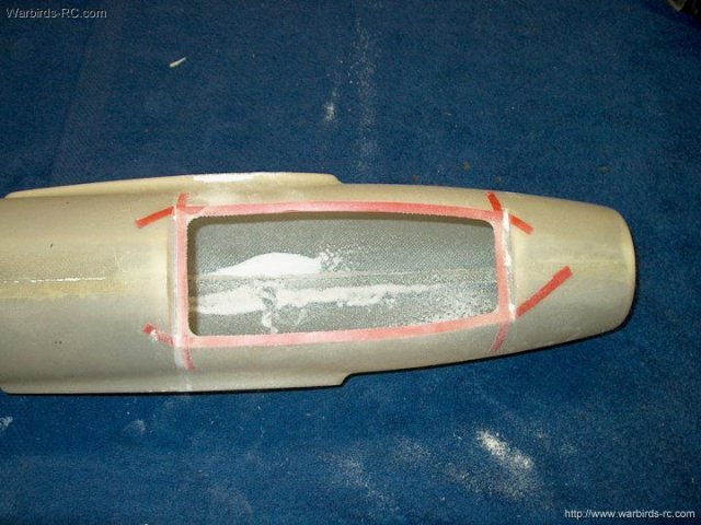
Area has been shaped and is now fine
sanded with 320 grit to round the edges inside to out
| |
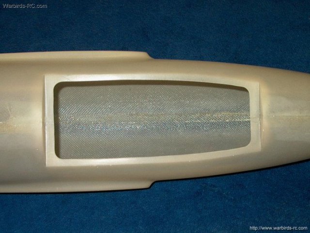
Cockpit area shaping shown
completed | |
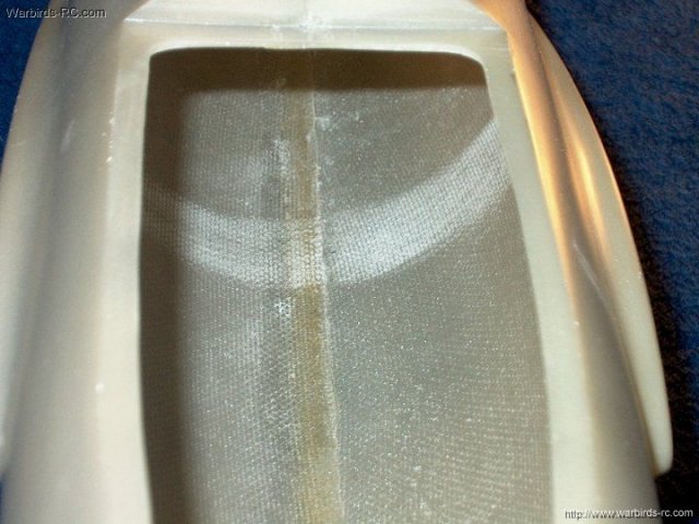
Use 60-80 grit sandpaper and sand a 1"
wide area inside the fuselage centered on the main former
location for good glue purchase | |
Apply 15-30 minute epoxy to the edge of
the main former | |

The Main Former is installed with the rear
of the former on the marks | |
Epoxy resin is mixed and three stips of
5oz glass cloth are cut. One strip is 5" long and the other 2
are 2 1/2" long | |
Resin is applied in the fuselage area to
glass the former to the wall | |
Glass strips are installed as shown and
excess resin is removed | |

Five 1" x 1" strips are cut, soaked in
resin, then applied to the rear of the main former. Excess
resin is then removed | |
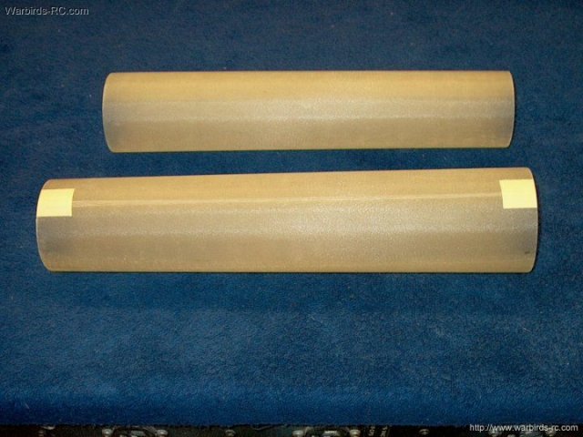
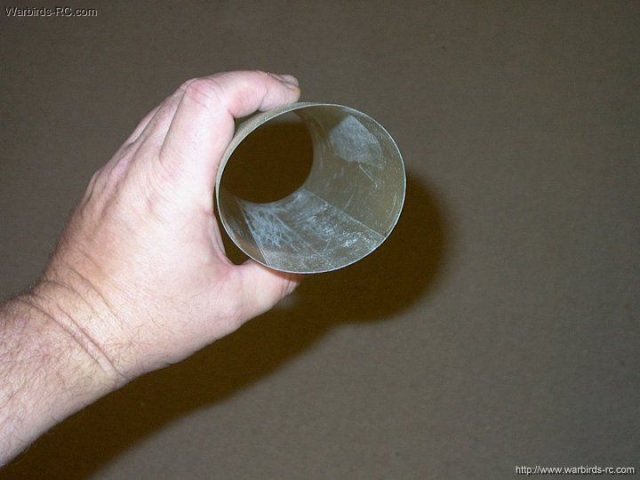
Two fiberglass thrust tubes are supplied
with the kit. The longer tube is used for the intake
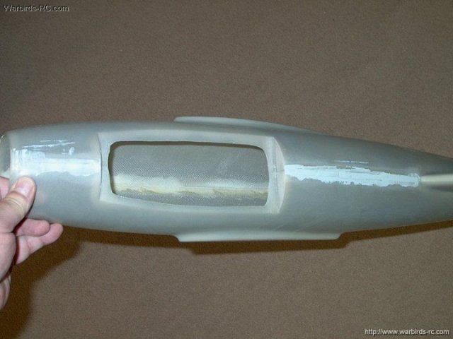
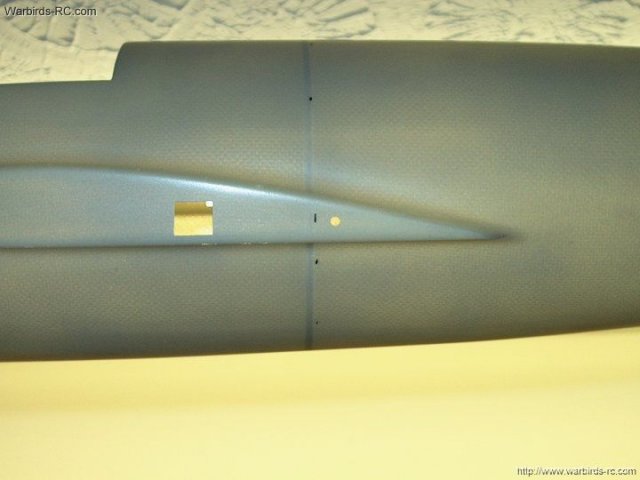
| |
The intake is temporarily installed in the
fuselage 1/4" away from the front of the main former and
measured, then rough cut to length | |
For a HW609 or other larger fans, the
small end is used at the intake opening, while the larger end
fits right over the fan. Also if you are using a larger fan,
do not trim the duct and you can omit the next several steps
and proceed to glassing your intake. For the MiniFan 480, one
side of the intake duct was trimmed just enough to straighten
the cut from manufacturing. Note that the smaller end of the
tube is used on the fan side | |
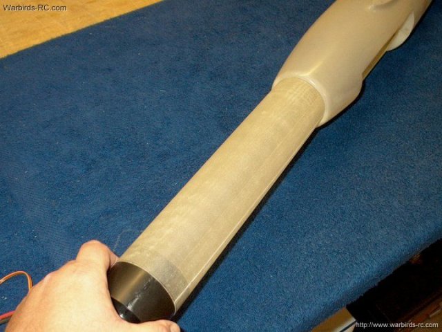
Make sure the intake on the fuselage is
round, then the duct is installed and expanded to fit loosely
in the opening. The loose fit of about 1/64" or more is
required as the tube will be glassed later and this will
increase its thickness | |
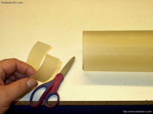
The intake tube is removed and marked for
cutting off the overlap | |
A yardstick and knife is used to trim the
excess off the intake duct. Be sure to cut excess the side
that was not previously straightened
| |
The excess is removed from the duct
| |
Packing tape is applied from the inside to
one side of the duct | |
The other side is pushed flush and the
tape is pressed down. You can use a wooden dowel to reach the
center area | |
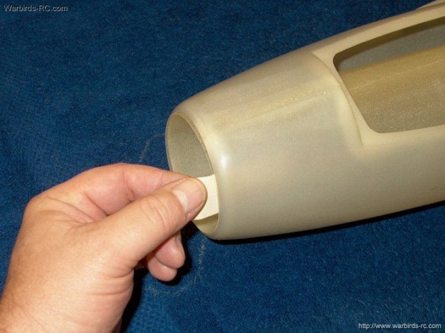
The intake duct end is checked for
fit | |
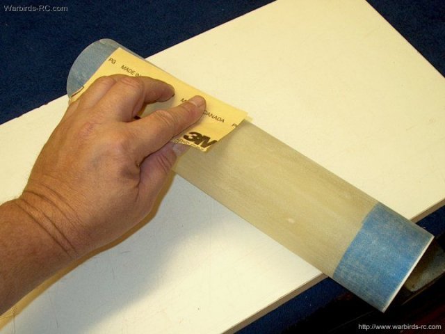
Before glassing the duct, the inside ends
are covered with blue masking tape so excess epoxy will not
drip on the inside. Then the intake is sanded on the outside
with 100 grit to rough it up for good glue purchase
| |
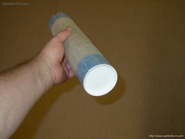
Then ends of the tube were capped with
spare items in the shop to help keep them round during the
glassing. A plastic cap from balsa filler was used on one end
and a 1/4" thick balsa disk was made for the other end. Make
sure what you use fits well; if too large, it can expand and
open a crack at the seam | |

This Website and all documents herin are Copyright © 2012 www.scalerocketry.com -
All rights reserved.
| |