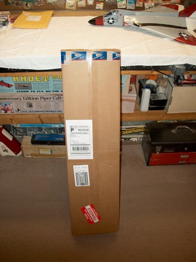
01- The HET-RC Sniper double boxed as it
arrives from Warbirds-RC | |
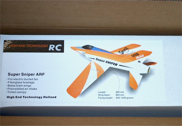
02 - Front label shows a picture and
specification. | |
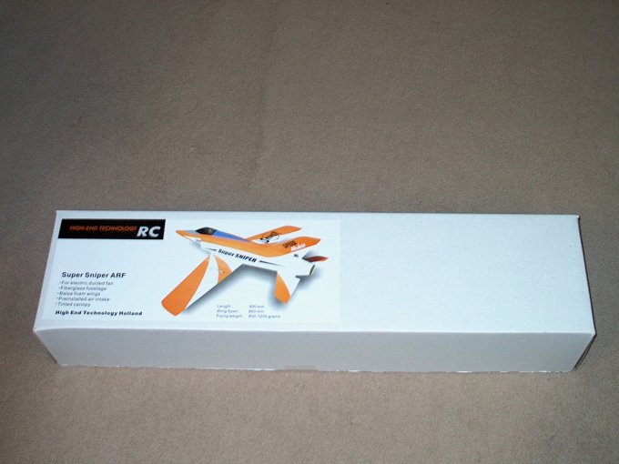
03 - The package, in good shape with no
shipping problems. | |
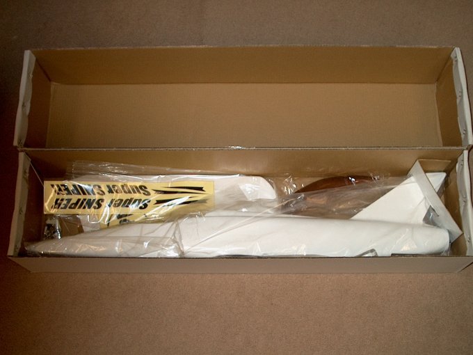
04 - Inside the box reveals a well packed
kit, typical of HET-RC. | |
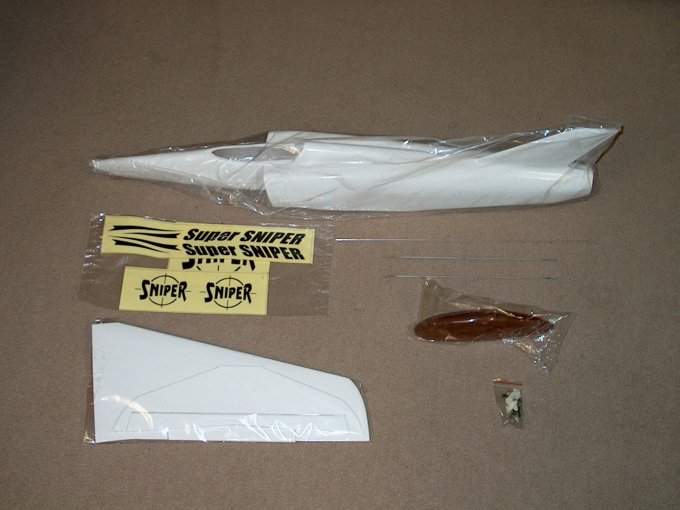
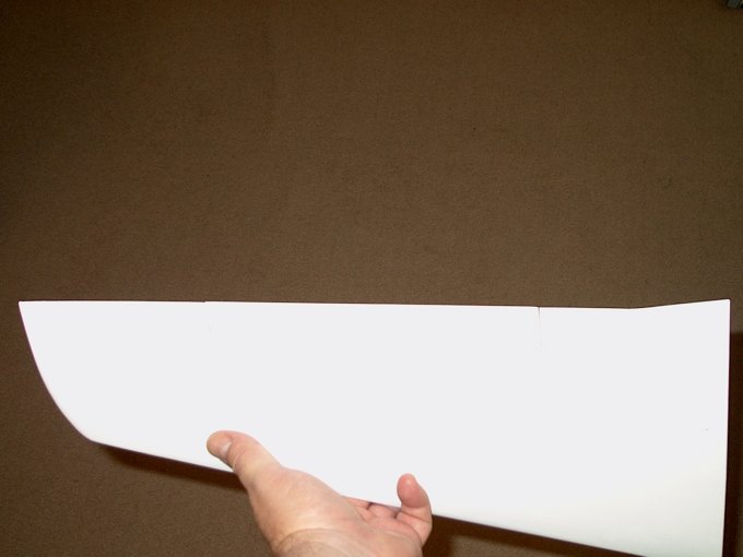
05 - The components include a fiberglass
fuselage, two wing halves, a horizontal stab, canopy, hardware
bag and decals. | |
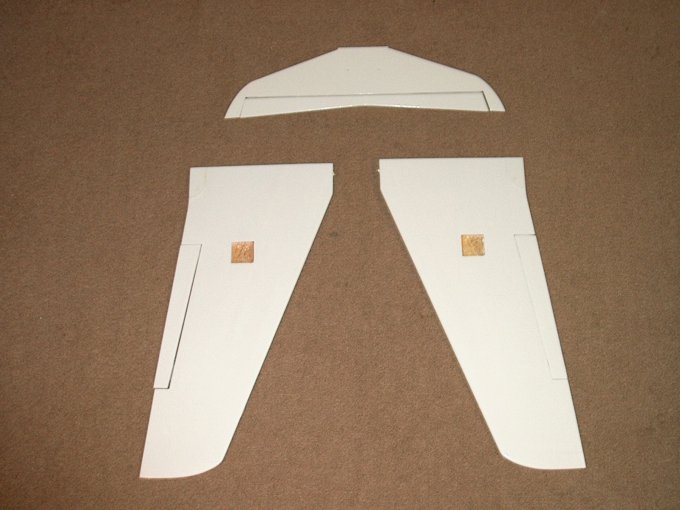
06 - Wing sections and stab come
pre-covered in plastic covering, note though that the control
surfaces are not yet glued. | |
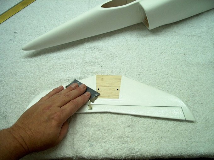
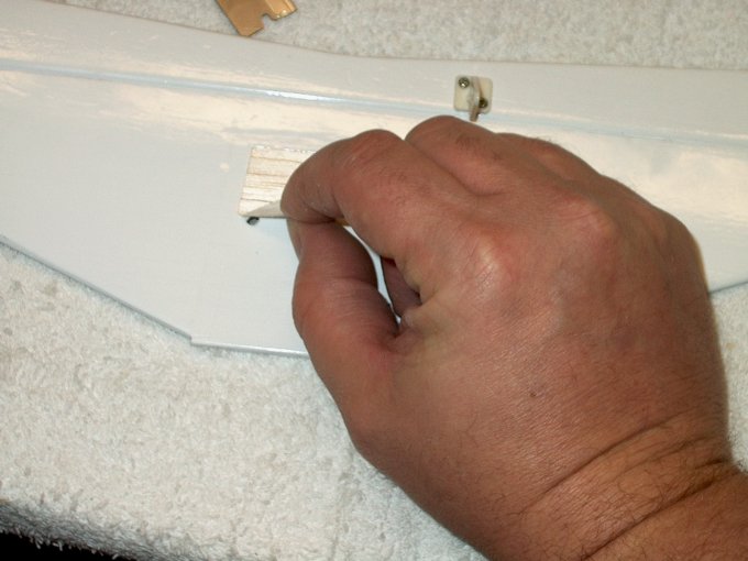
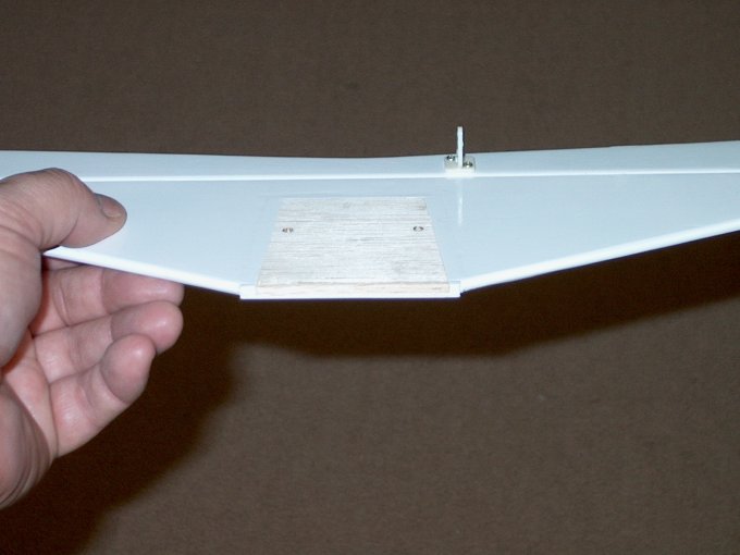
07 - Hardwood plates support the wing
mountings holes. | |
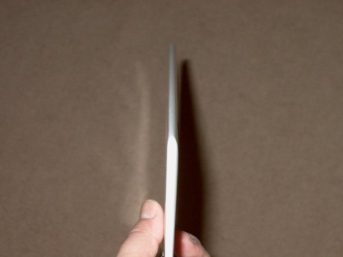
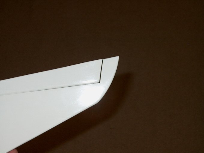
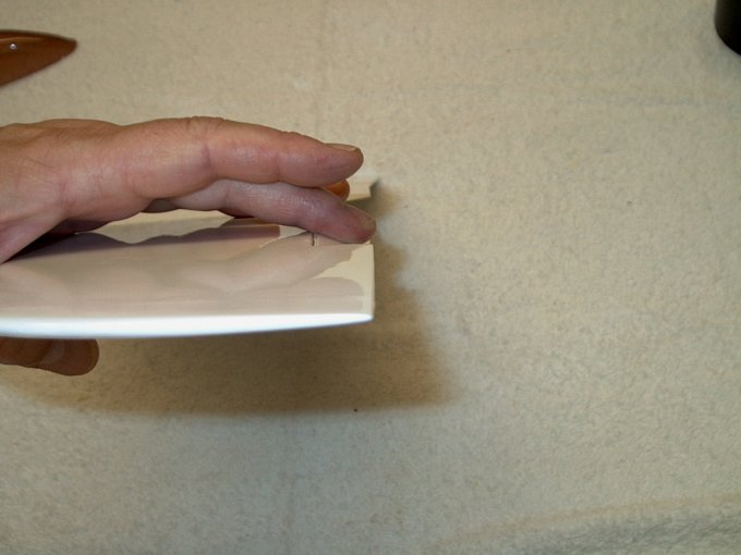
08 - The leading edge of this
semi-symmetrical wing is shaped well.
| |
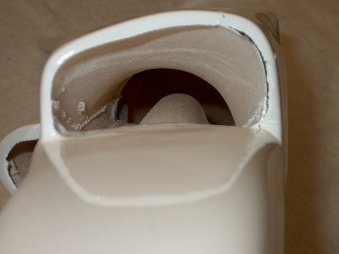
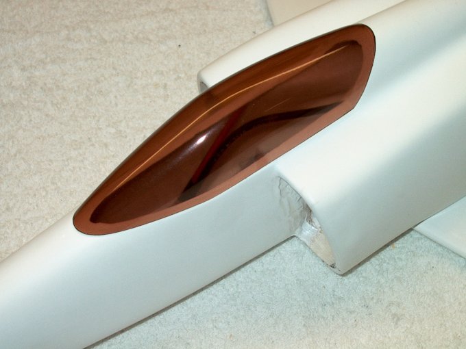
09 - The intake duct work is made from
glass, it's not super smooth, but has been finished
well. | |
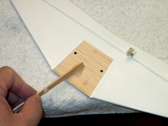
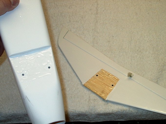
10 - Tow hook location is beefed up
inside. I noticed all the mounting points for the wing, tow
hook and tail feathers have hardwood supports epoxied in place
inside... a nice touch. | |
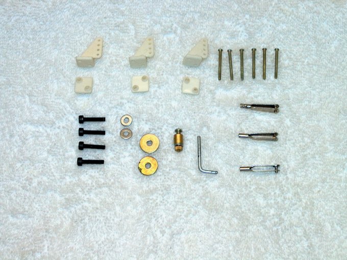
11 - Hardware package should include the
following: 3 Horns 6 Horn mounting screws 3 Clevis' 4 Wing /
Tail mounting bolts & washers 3 Control rods 1 Tow hook
| |
12 - Another nice feature is the aileron
servo wire exit holes, which have been pre-made.
| |
13 - The build begins with the elevator
hinges removed in order to mark the center lines.
| |
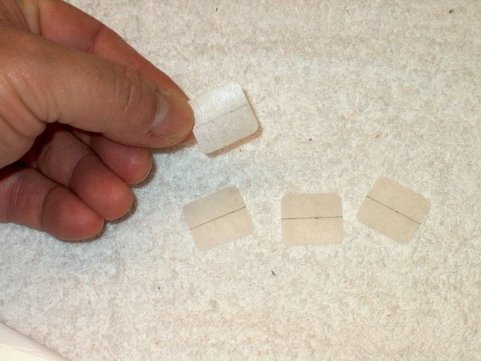
14 - Hinges are inserted up to the line
inside the horizontal stab. They are placed with their left
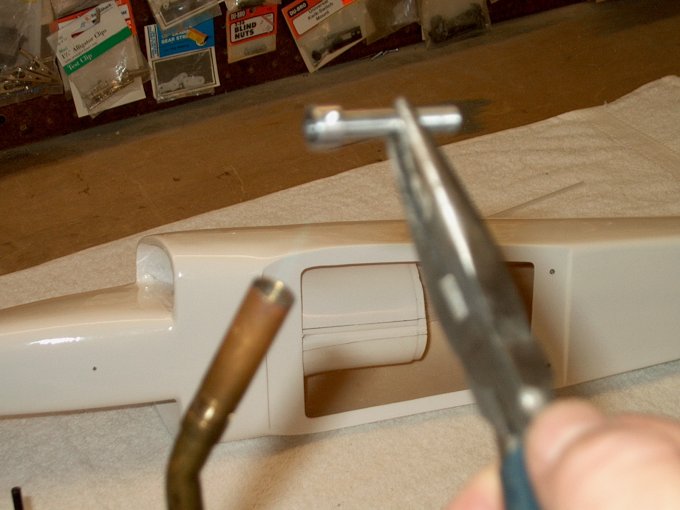
side 3/8" and 3" away from the end joint.
| |
15 - Thin CA glue is used to mount the
hinges... it will "wick" into the joint.
| |
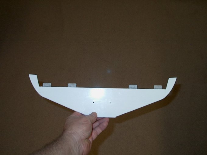
16 - Horizontal stab with hinges
installed. | |
17 - The elevator is installed on the
stab. Make sure it is evenly spaced from the tip on both sides
before gluing. | |
18 - Elevator is moved downward before
gluing, allowing it to pull away a bit from the stab so it
won't bind during use. | |
19 - Elevator installed on stab and glued
in place. Once again, make sure the ends are evenly spaced,
then use thin CA to attach the elevator.
| |
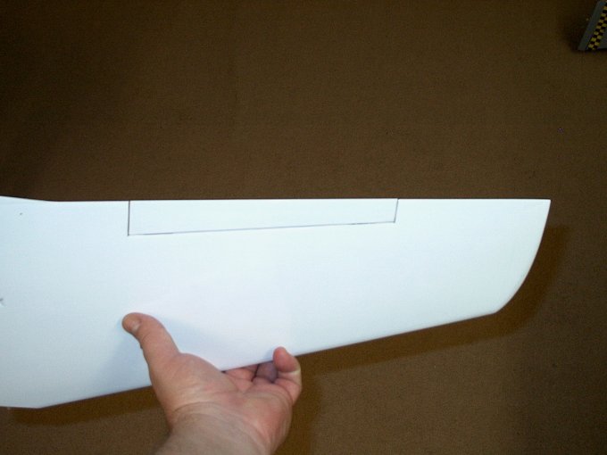
20 - Marking center lines for the aileron
hinges . | |
21 - Hinges are installed 1/2" from each
side. | |
22 - Hinge is glued in place and aileron
is shown being installed. | |
23 - Aileron installed.
| |
24 - Aileron flexed downward to have it
space itself slightly away from the trailing edge of the wing
for freedom of movement . | |
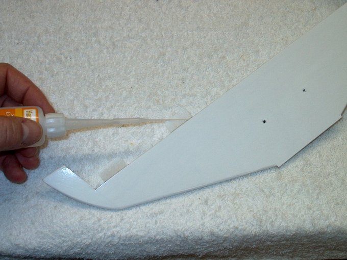
25 - Next, the aileron is glued in place
with thin CA. | |
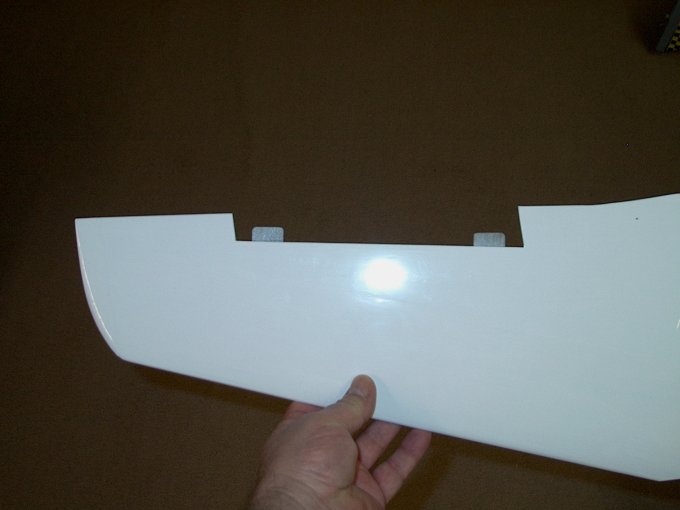
26 - The second wing half showing hinges
installed. | |
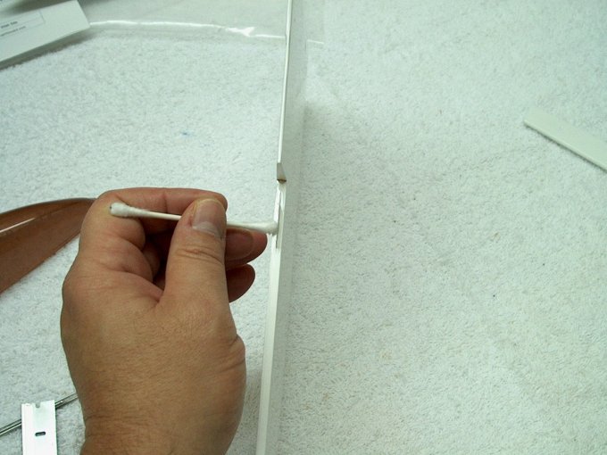
27 - Using a Q-Tip makes a nice cleanup
tool for excess thin CA. | |
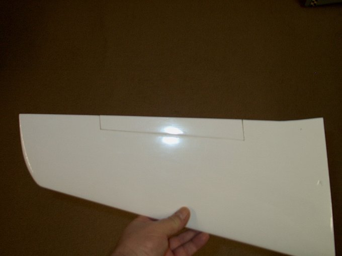
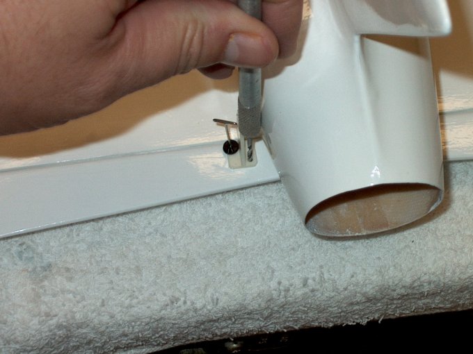
28 - Aileron fitted to second wing half.
| |
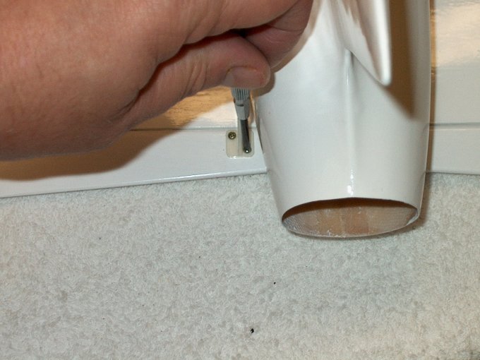
29 - Once again, the aileron is flexed to
space it from the trailing edge. | |
30 - Second aileron glued in place.
| |
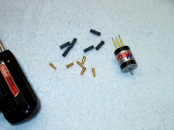
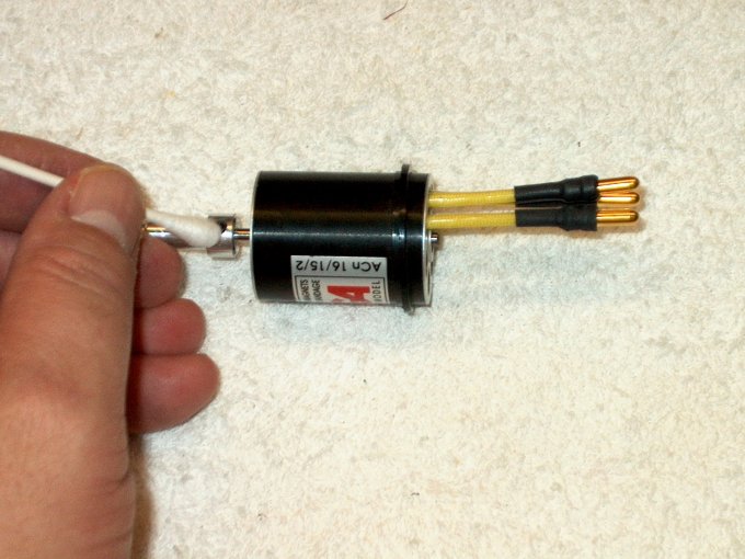
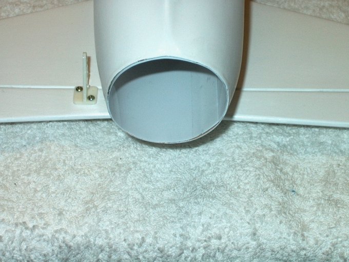
31 - Preparing the power plant.
| |
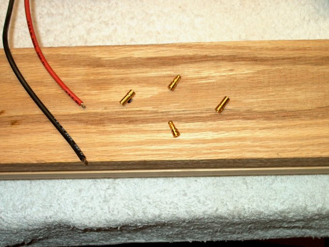
32 - 3.5mm plugs are installed on the
motor. | |
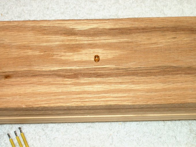
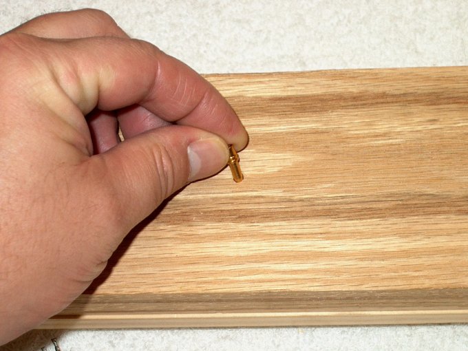
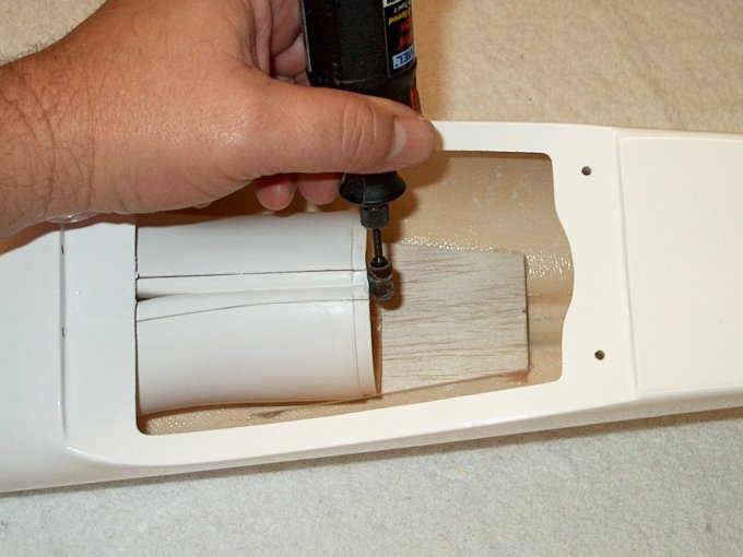
33 - A piece of hardwood makes a good plug
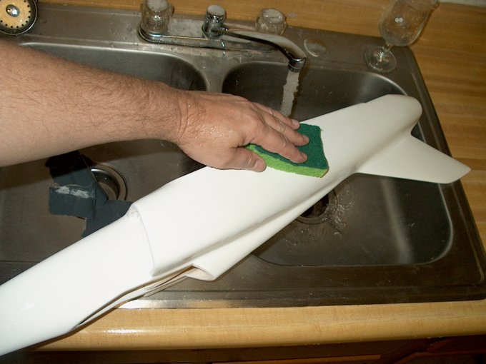
holder. | |
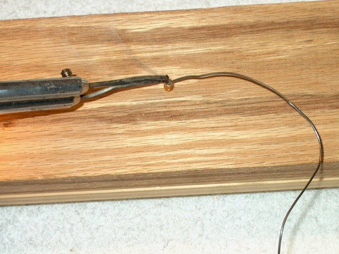
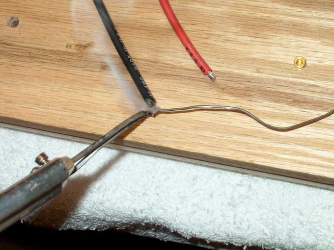
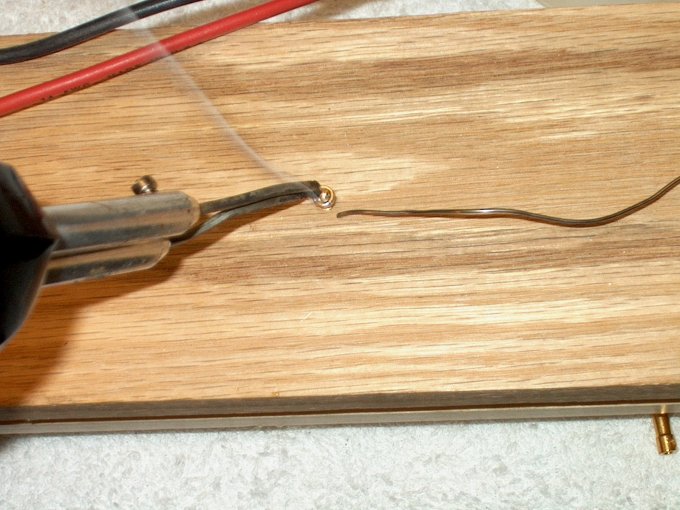
34 - Filling the cup with solder.
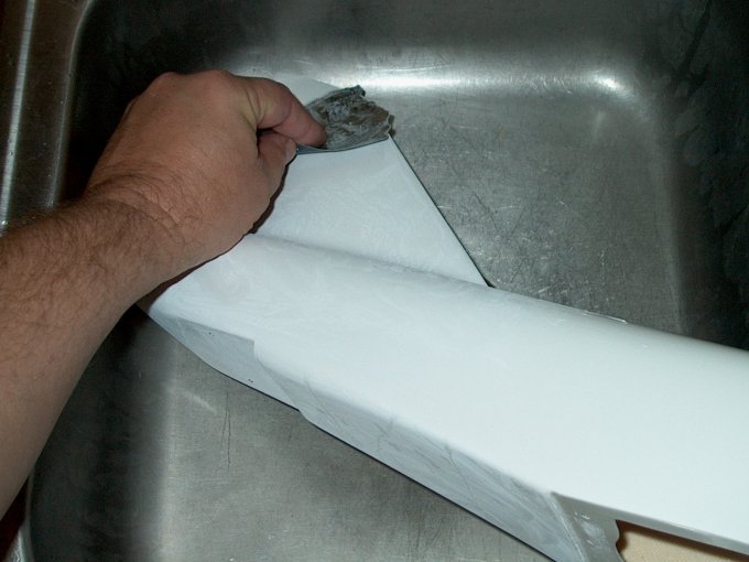
| |
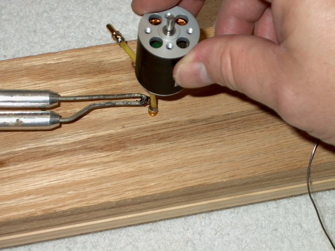
35 - Motor lead and plug are heated, then
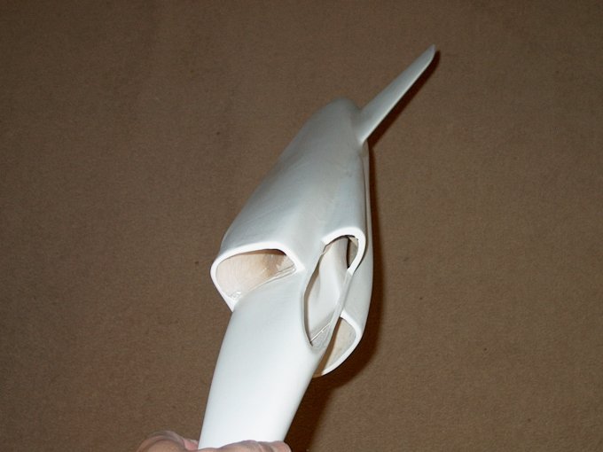
the lead is pushed down in place. | |
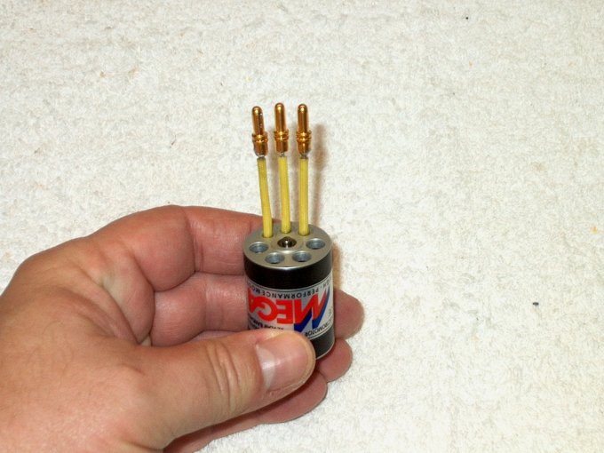
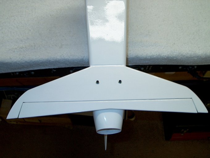
36 - All three leads connected.
| |
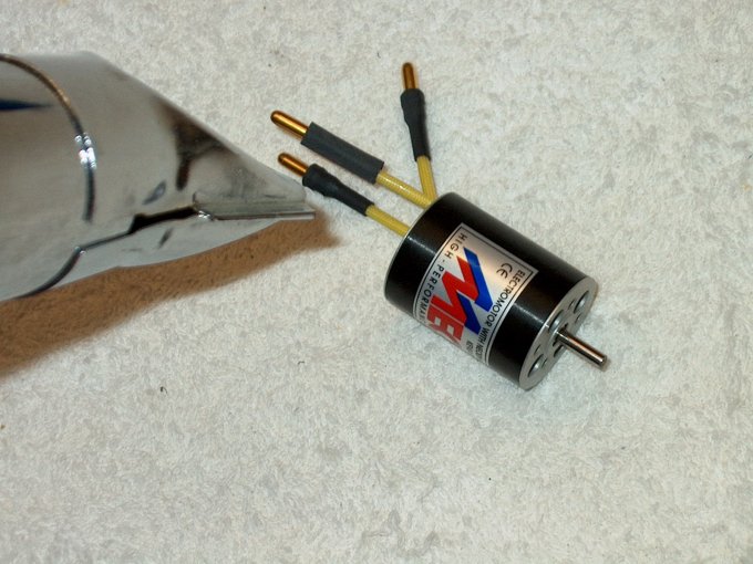
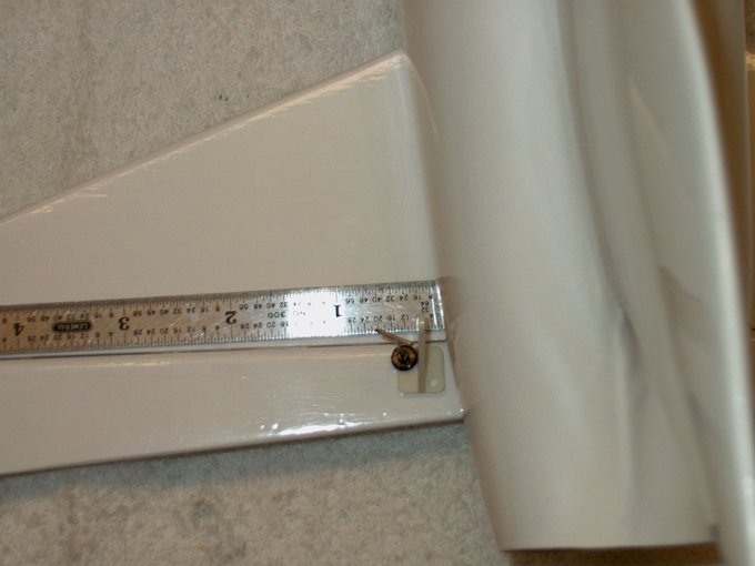
37 - Adding heat shrink to the
plugs. | |
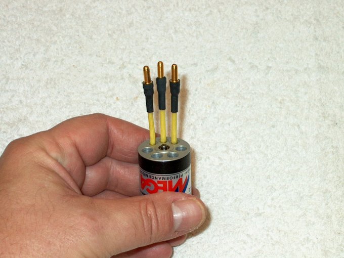
38 - Motor assembly completed.
| |
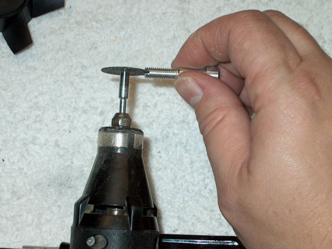
39 - Preparing to assemble the MiniFan480,
the shaft adapter is slotted at the tip so a screwdriver can
be used later to help tighten the nut.
| |
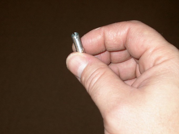
40 - Shaft adapter slotted.
| |
41 - Heat the shaft adapter with a
torch... a hair dryer or heat gun can be used as an
alternative. | |
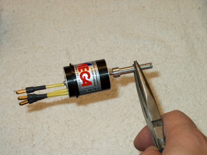
42 - Heating the shaft is necessary as it
is slightly undersized on purpose to insure a tight fit to the
motor shaft. | |
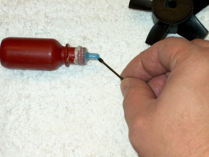
43 - Loktite is used on the setscrew.
WARNING - Not not allow any Loktite to come in contact with
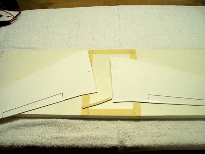
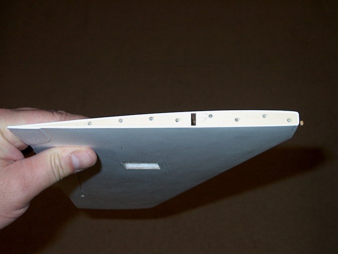
any part of the fan. | |
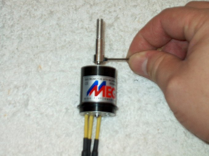
44 - Set screws are installed in the shaft
adapter and tightened. | |
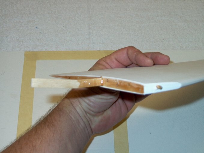
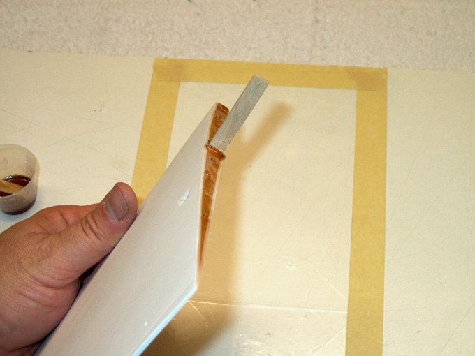
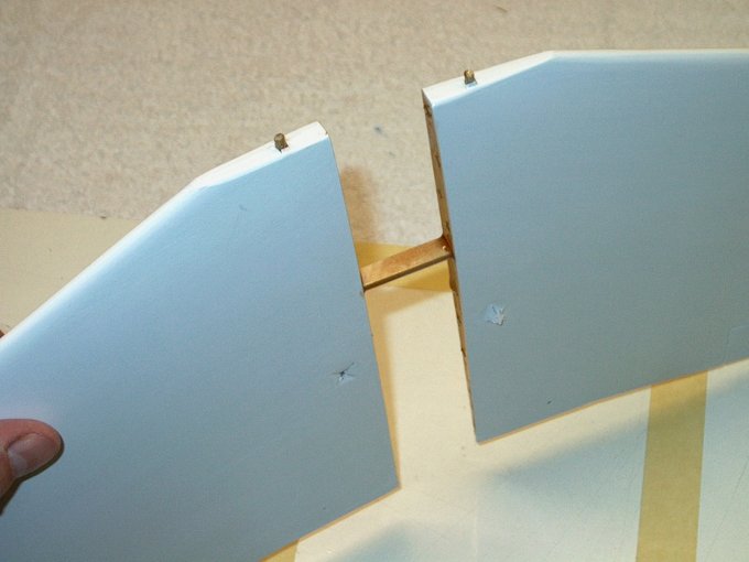
45 - Use a Q-Tip to clean off all excess
Loktite. | |
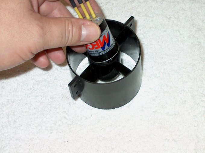
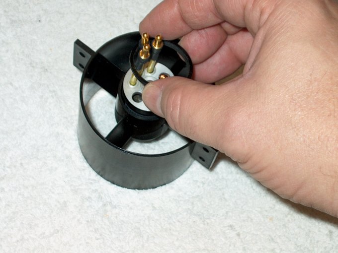
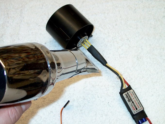
46 - Install the motor in the fan shroud.
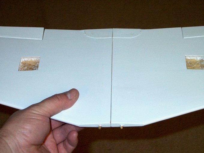
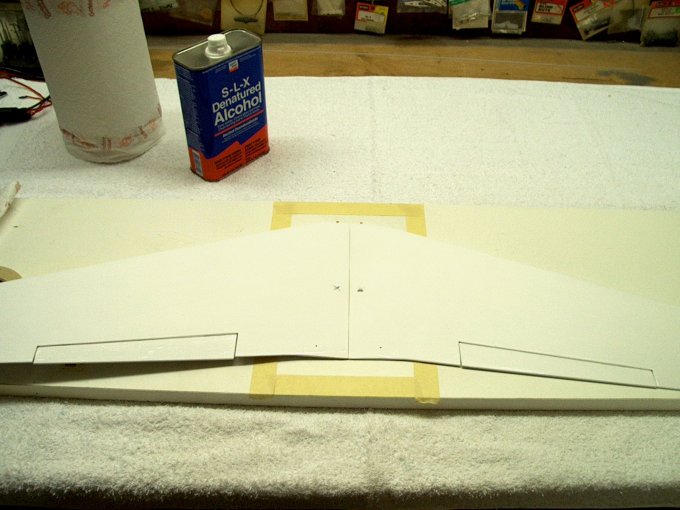
| |
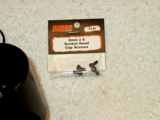
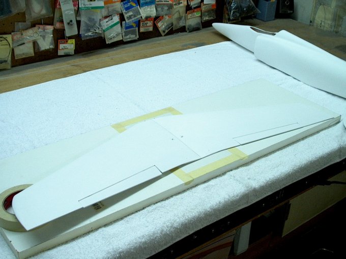
47 - The screws that come with the Mini480
fan are 2.5mm, so you will need some 3mm bolts to mount the
motor to the shroud. | |
48 - 3mm bolts used to secure the motor.
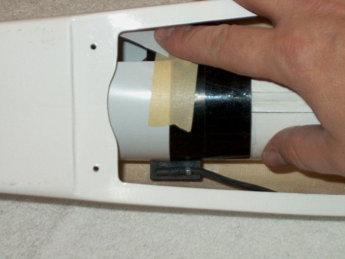
| |
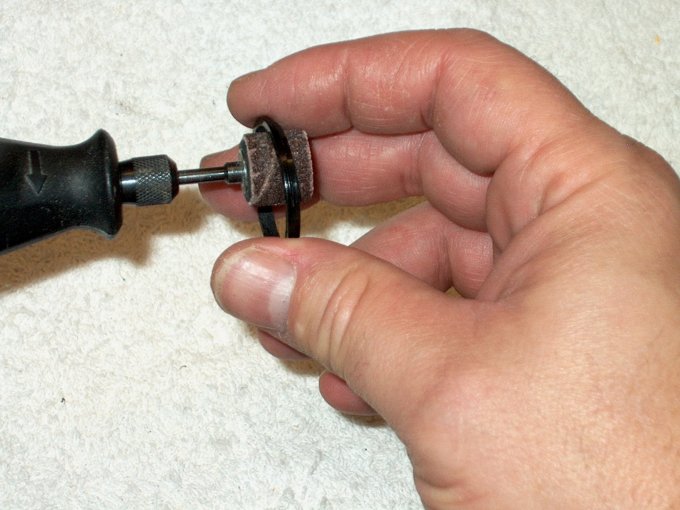
49 - A sanding wheel opens up the plastic
spacer ring so it will fit over the motor.
| |
50 - Ring checked for fit.
| |
51 - Ring slipped over the rear of the
motor. | |
52 - The ring is seated flush with the
rear of the shroud. | |
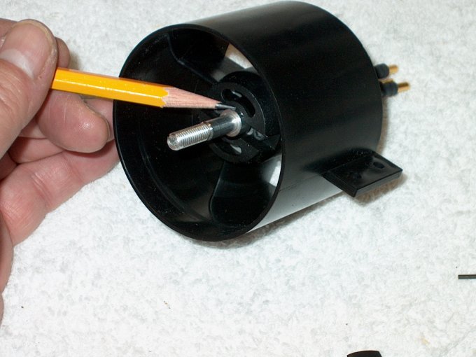
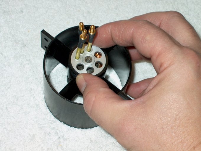
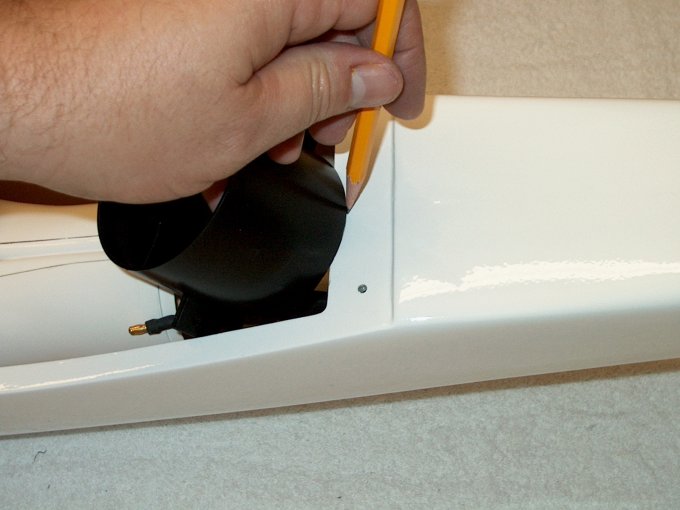
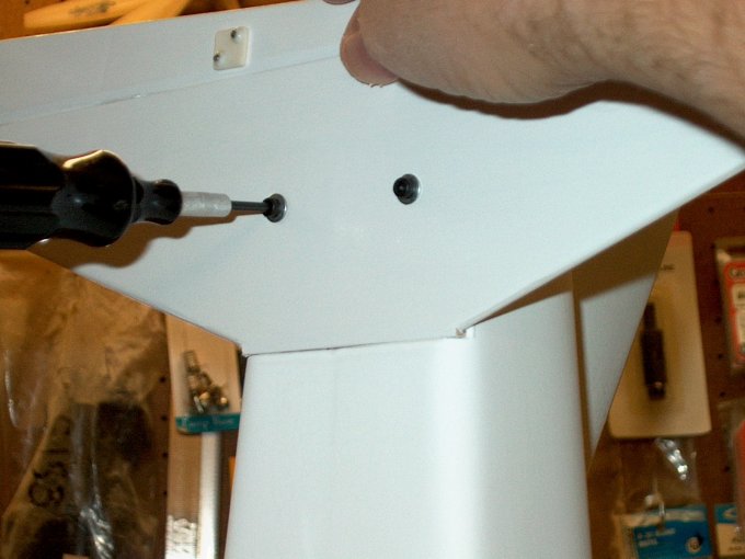
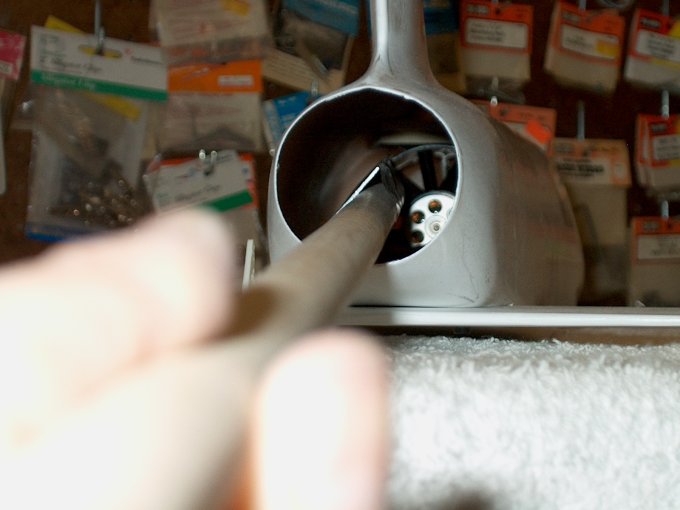
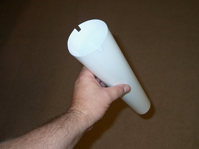
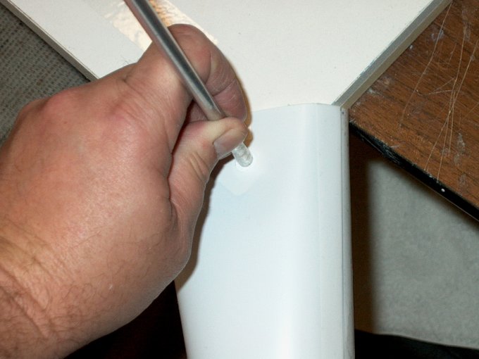
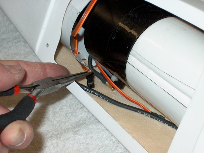
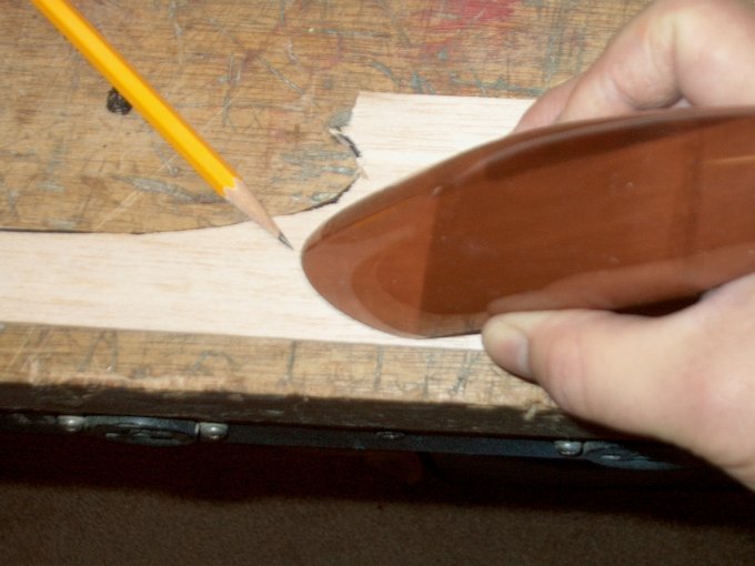
53 - Important: Check to make sure the
shaft base protrudes at least 1/64" from the fan shroud face,
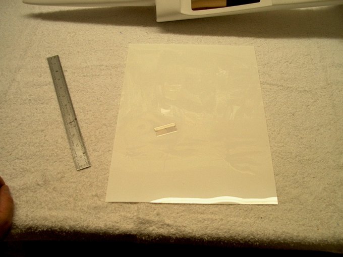
as shown by the pencil. If not spaced correctly, the rear of
the fan unit will rub the shroud once it is installed. If you
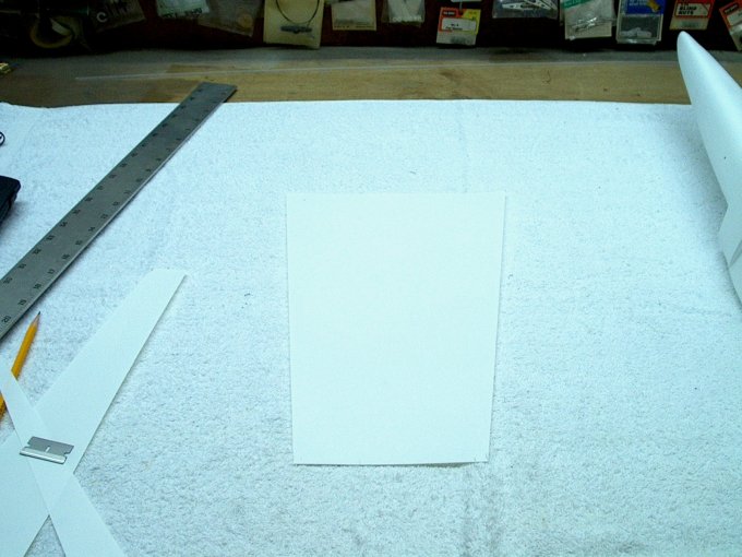
need clearance, remove the motor, loosen the shaft set screws,
heat up the shaft and pull it out a bit. Then reinstall and
check again. | |
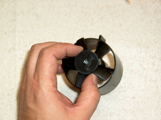
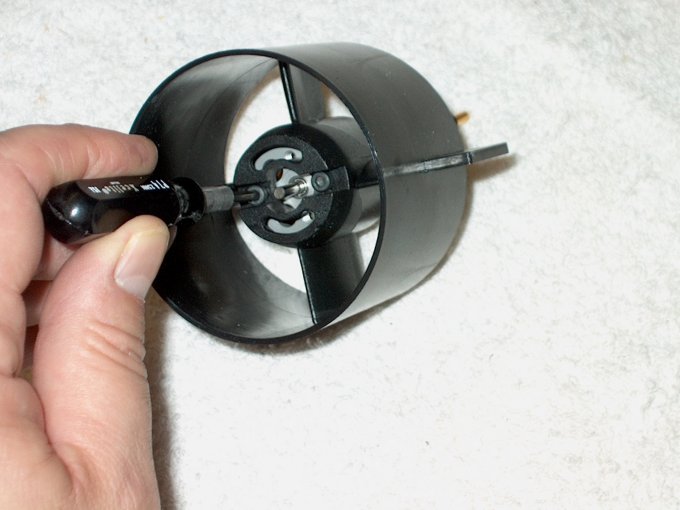
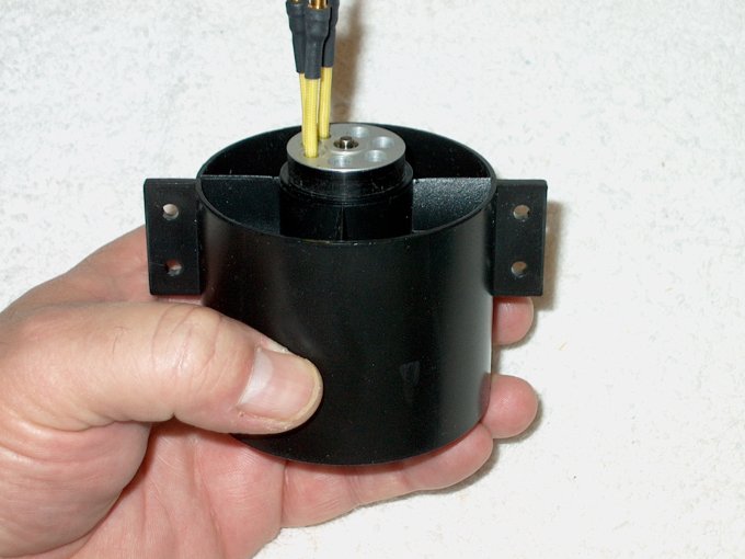
54 - Fan is installed on the shaft
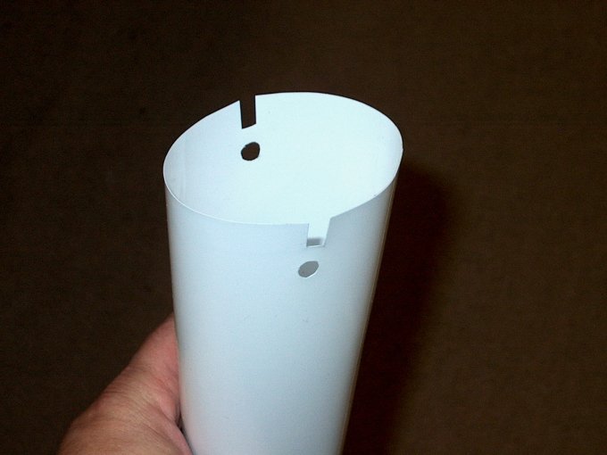
| |
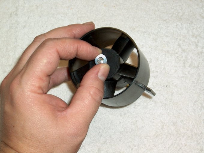
55 - Followed by a washer included in the
fan kit. | |
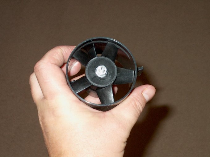
56 - Next, the aluminum nut is
installed. | |
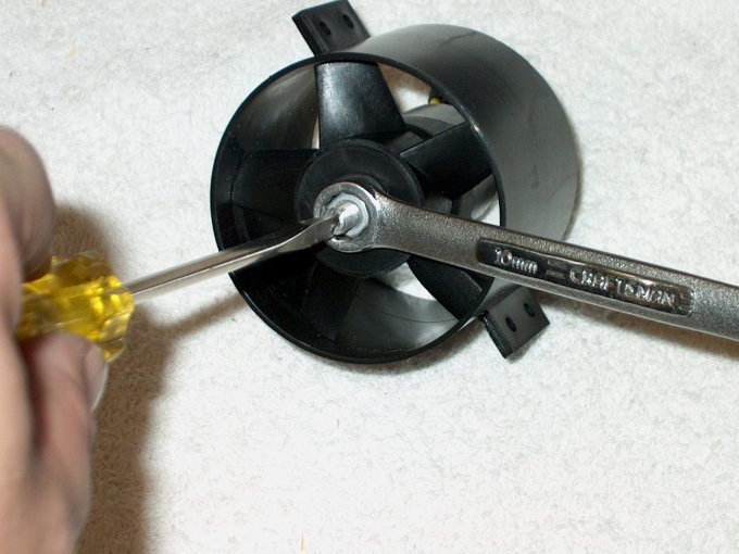
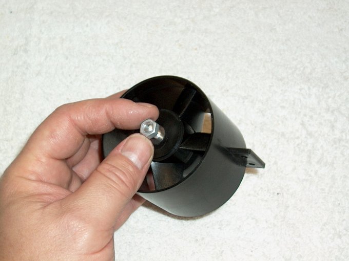
57 - Here is where the slot you made
earlier comes in to play. Using a screwdriver in the slot to
hold the shaft, tighten the fan unit.
| |
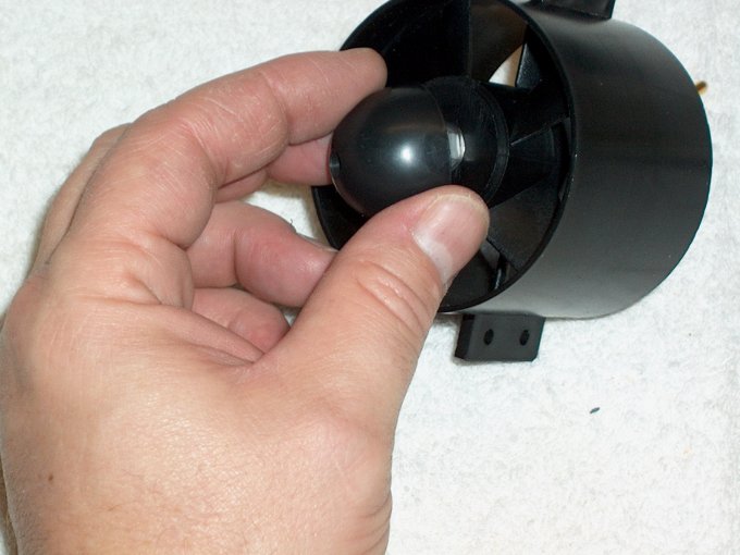
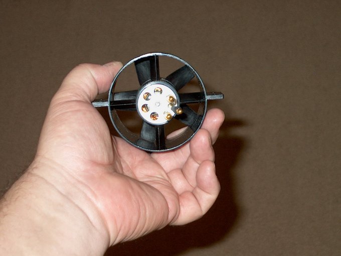
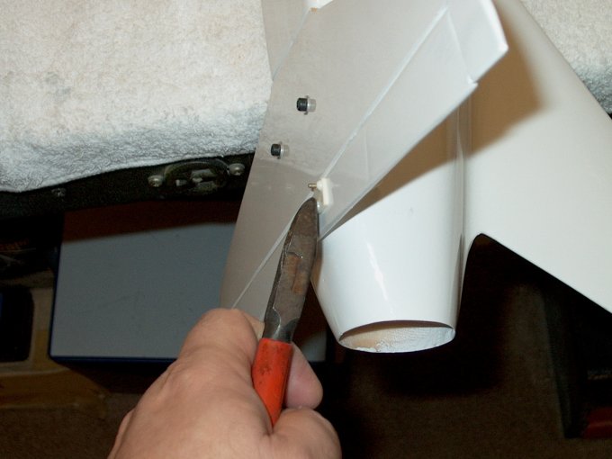
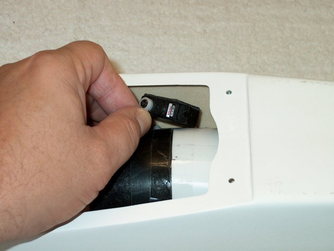
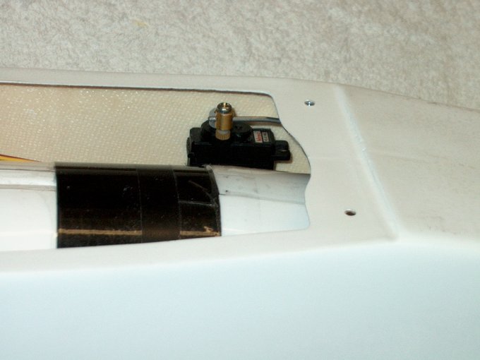
58 - Hub and retaining bolt installation
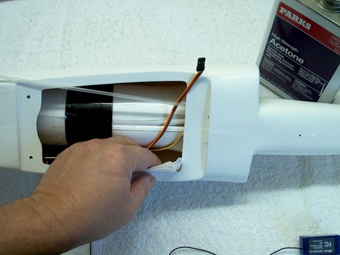
is optional. You can run the fan without the hub with almost
very low loss in power | |
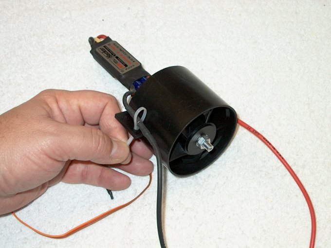
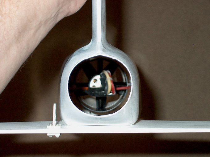
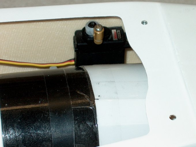
59 - Fan assembly completed.
| |
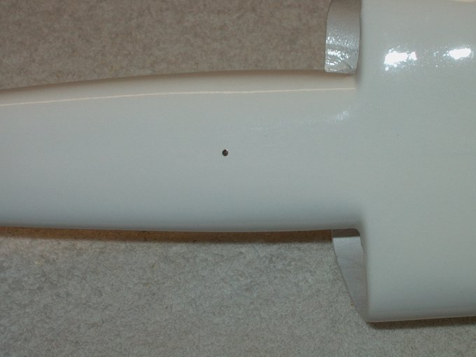
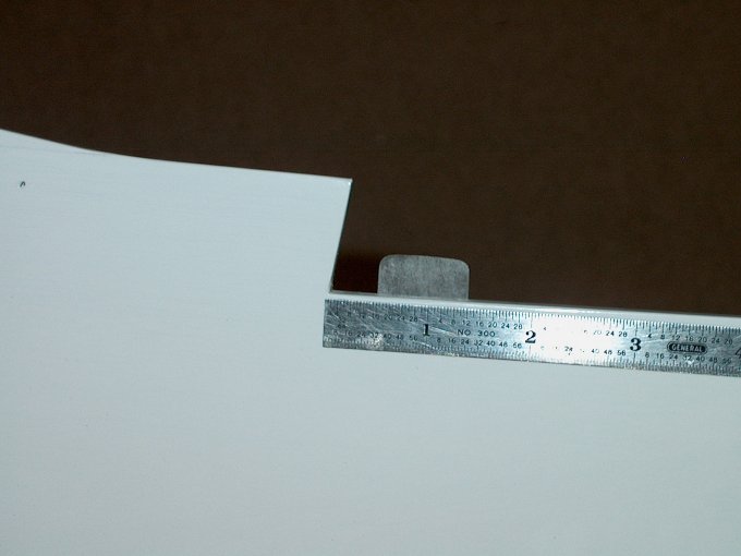
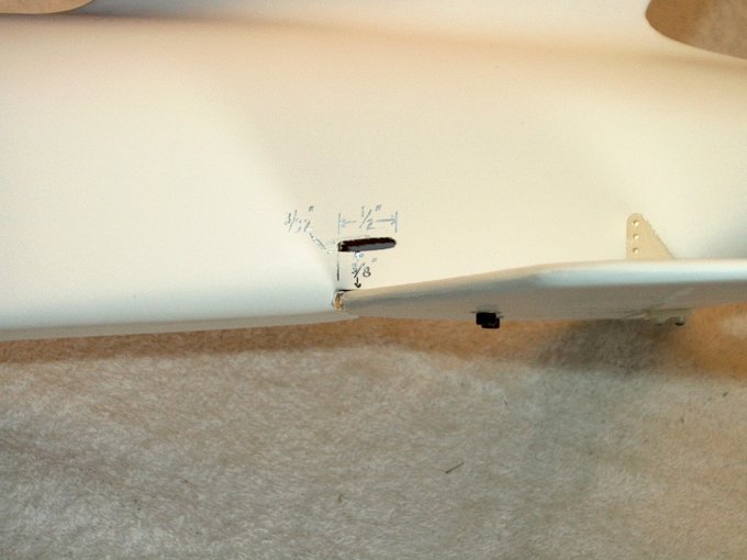
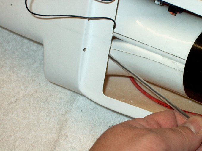
60 - VERY IMPORTANT: Please make sure
there is no rubbing or binding between the fan rotor and the
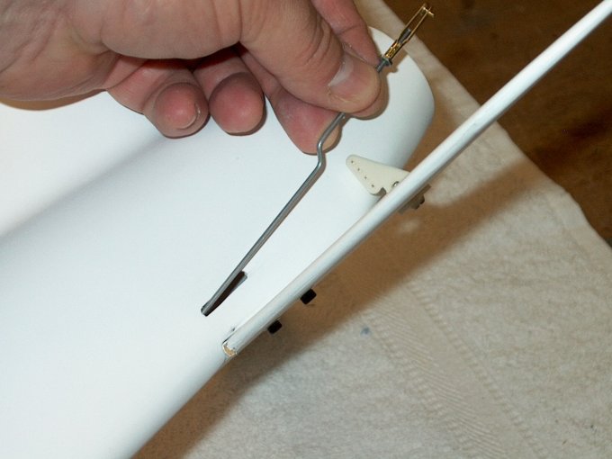
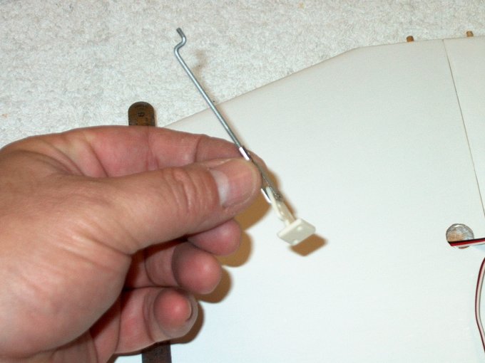
fan shroud. Now would be a good time to check, if the rotor
does not spin freely without making contact with the fan
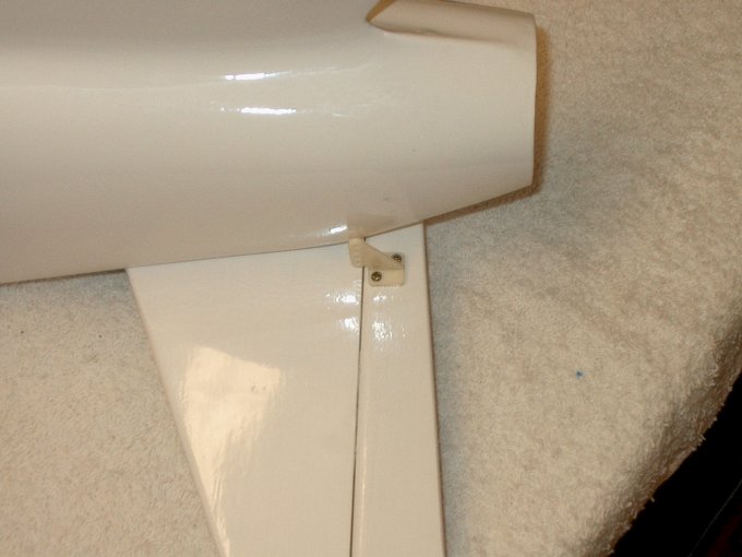
shroud, please go back to step #52 and check that you provided
adequate spacing between the adapter and the motor. Also, if
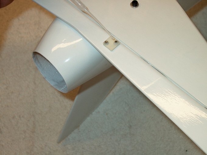
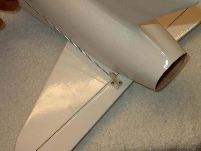
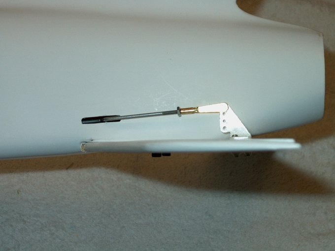
you use a lock tight type chemical to hold the aluminum nut in
place, make sure it does not come in contact with any of the
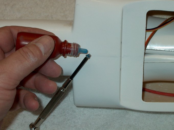
ABS plastic parts as it will soften and later destroy your fan
over a period of time. If you opt to use such a chemical make
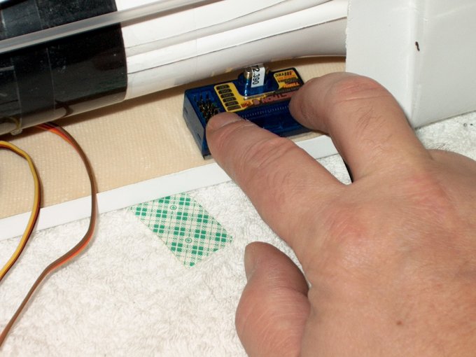
sure it only comes in contact with ONLY the metal parts and
wipe any excess away right away. | |
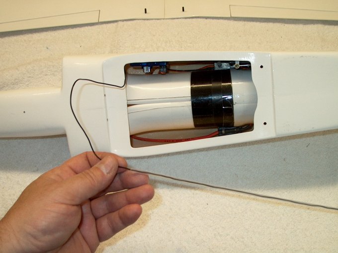
61 - Socket rear is pre-tinned and filled
with solder. | |
62 - Wire is soldered to the 3.5mm socket.
| |
63 - Both wires soldered.
| |
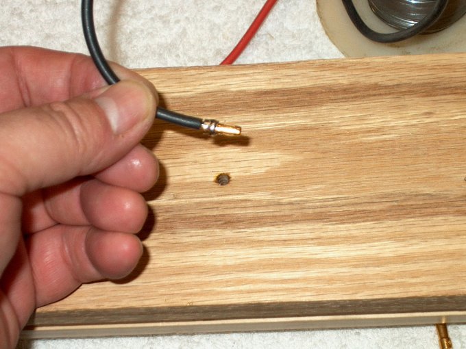
64 - Heat shrink tubing is added for
insulation. | |
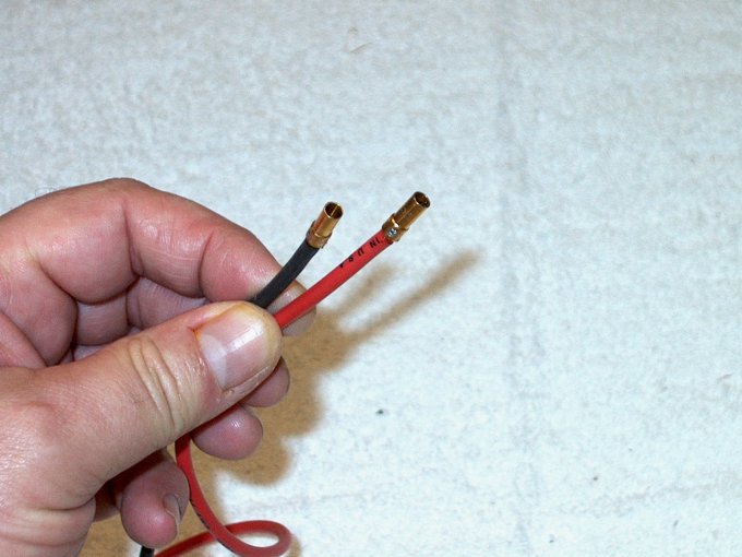
65 - The three sockets are connected to
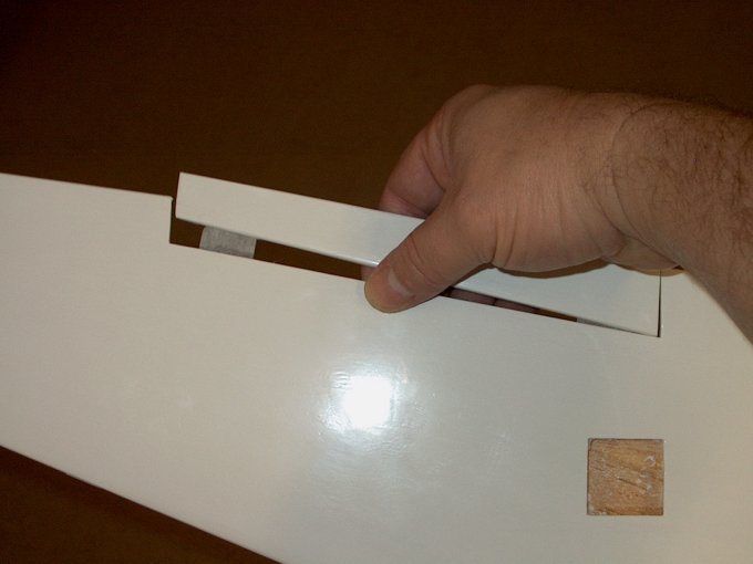
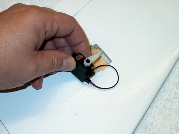
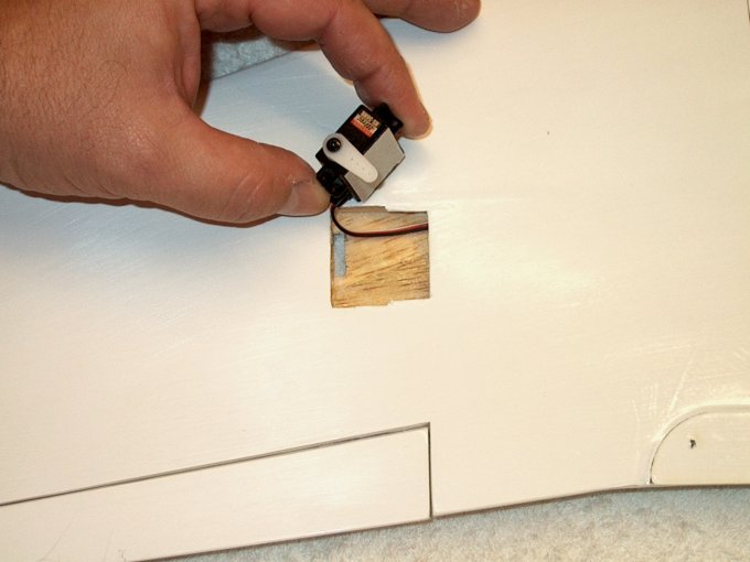
the motor wires on the ESC, while the two 3.5mm plugs are
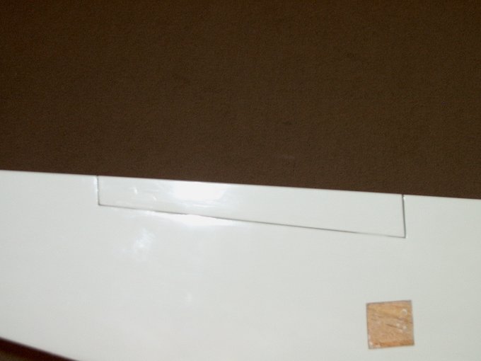
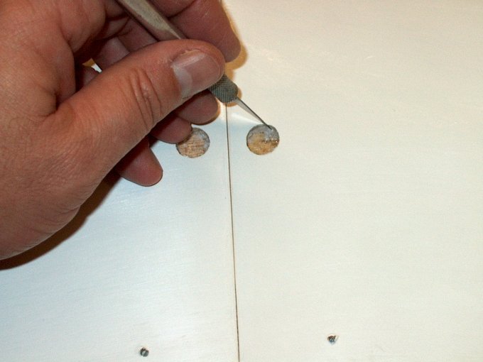
installed on the battery wire. | |
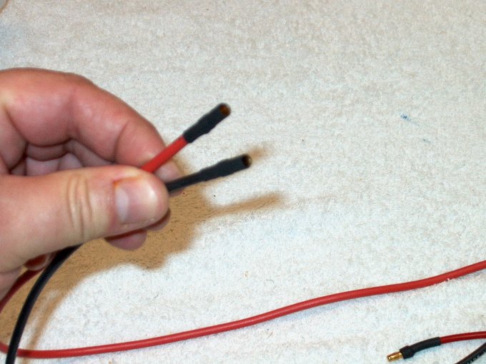
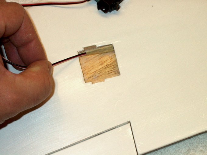
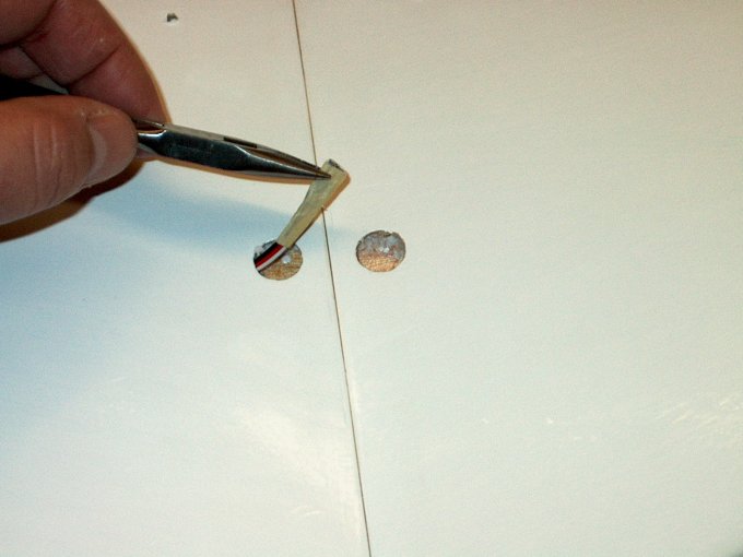
66 - Heat shrink tubing is added to finish
the sockets. | |
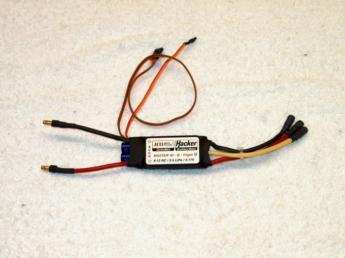
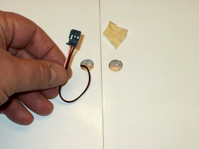
67 - A good quality ESC is
recommended | |
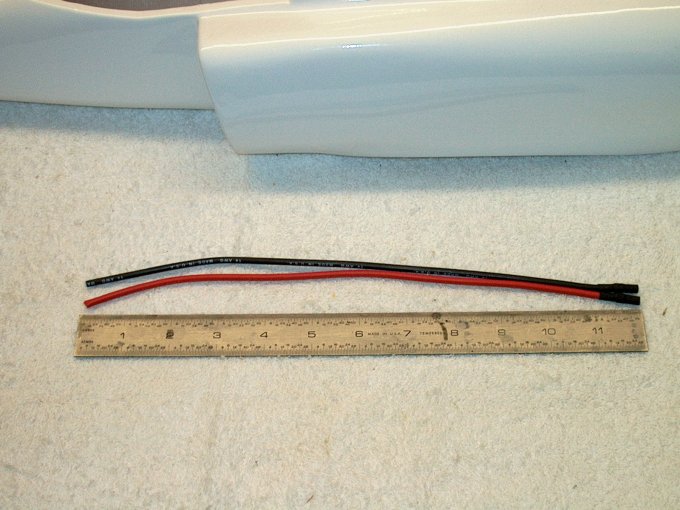
68 - The battery harness is cut to 12" in
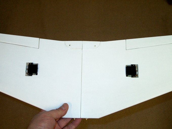
length. The fuselage is shown in the rear to show how the run
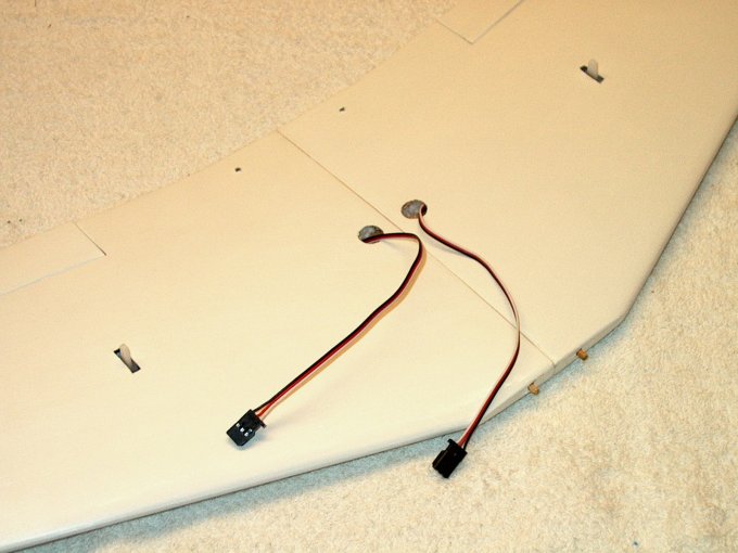
would fit, from the fan/motor location on the right to the
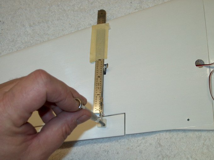
center of the battery compartment on the left.
| |
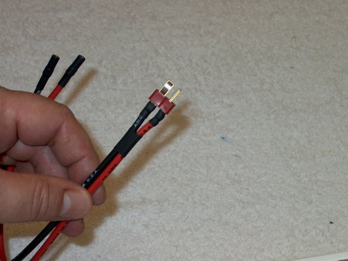
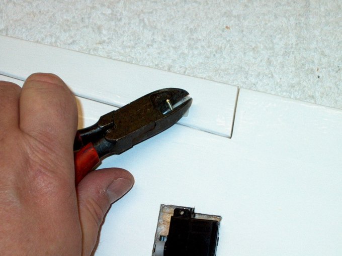
69 - A Deans "Ultra-Plug" is soldered to
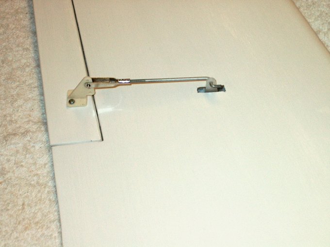
the other end of the harness. | |
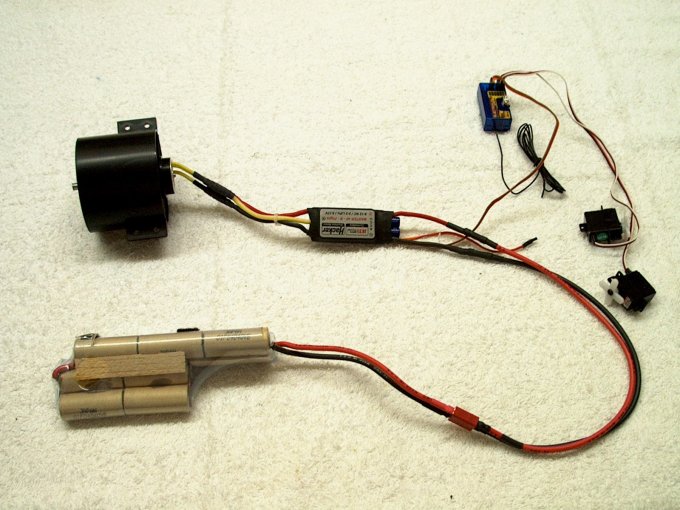
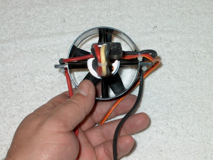
70 - The entire assembly is connected and
the fan is checked for balance. | |
71 - Heat shrink is applied to the motor
connector to insure they will not come loose.
| |
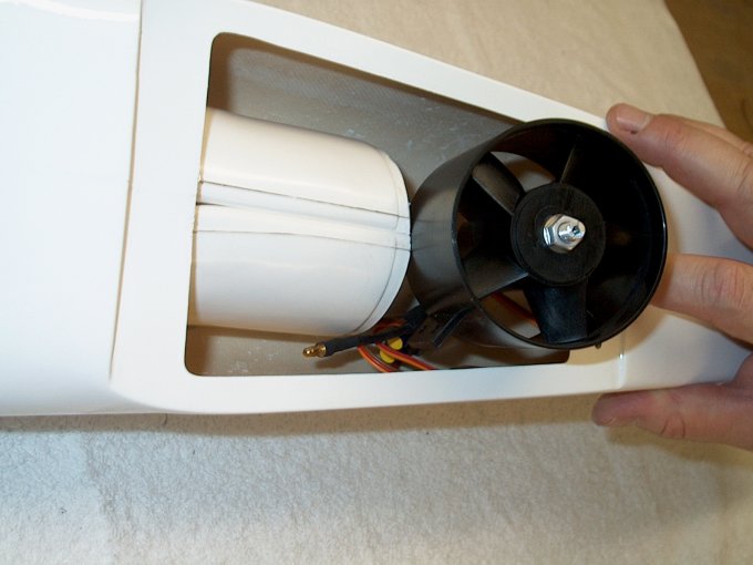
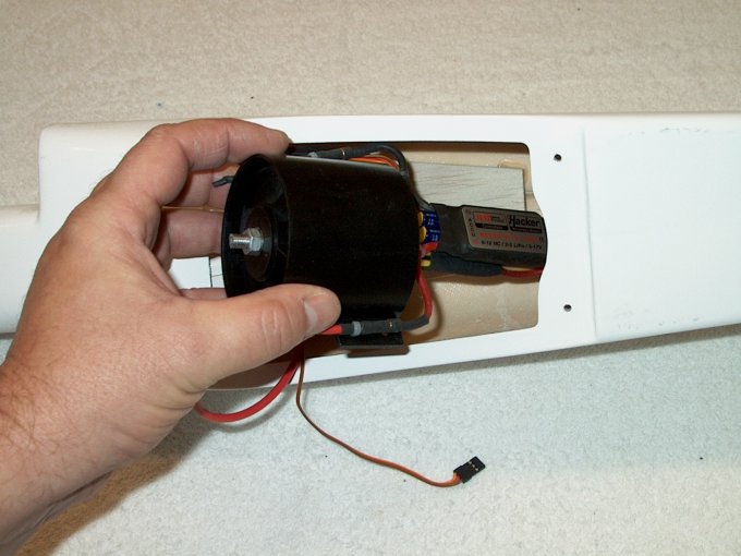
72 - Fan would not fit inside of the
fuselage as the opening was not large enough.
| |
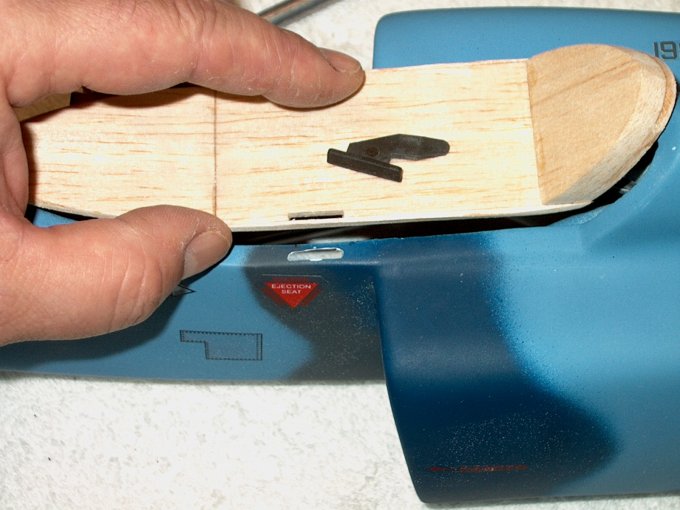
73 - The fan was positioned over the
opening and a pencil was used to mark the rear wing saddle
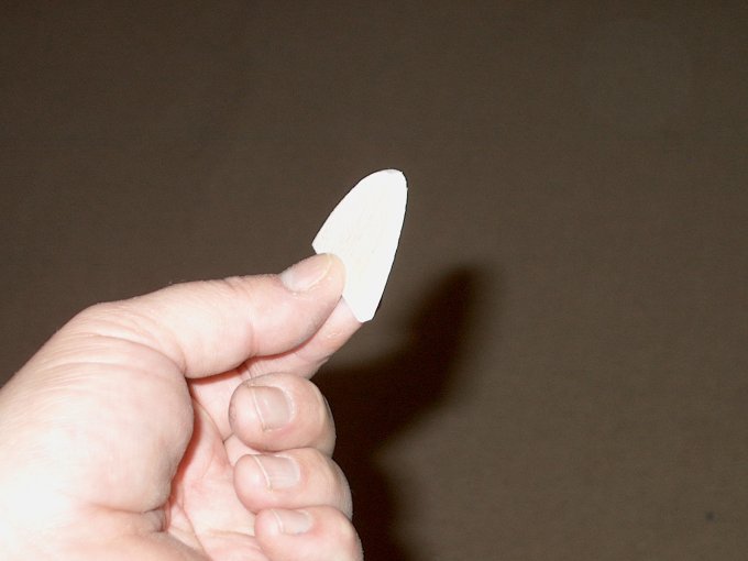
area. | |
74 - You can see where it was hitting...
DO NOT FORCE IT IN as you can crack the ductwork..
| |
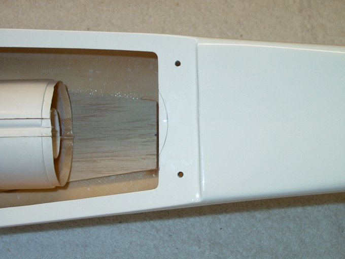
75 - Mark made from previous setup is
shown. | |
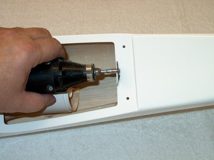
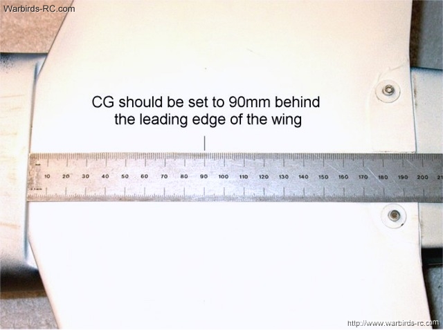
76 - A Dremel with a cutting wheel is used
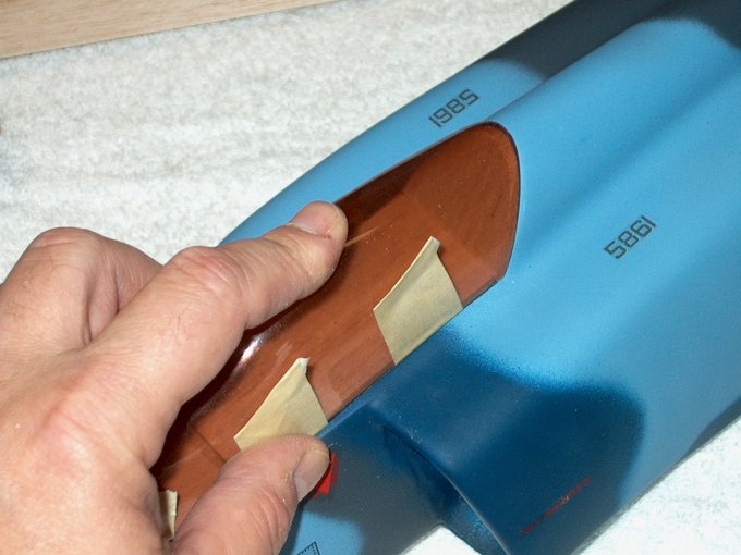
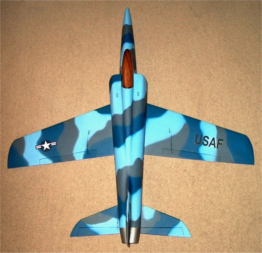
to rough cut the area. | |
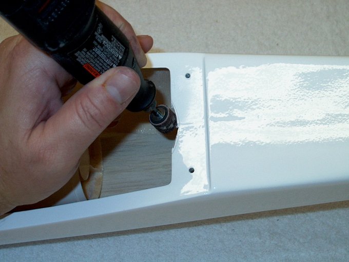
77 - Then a Dremel with a drum sander is
used to shape the opening. | |
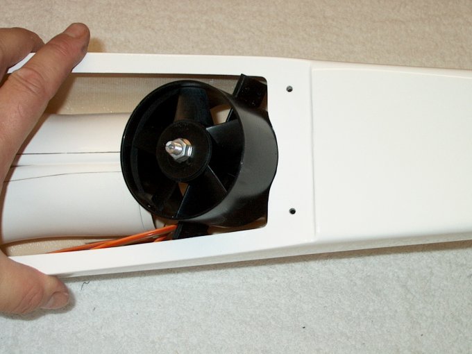
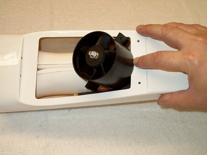
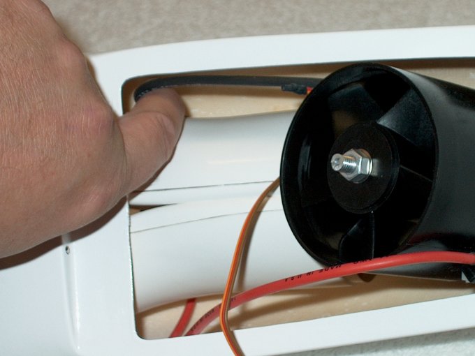
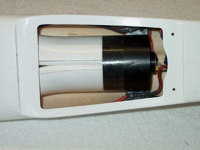
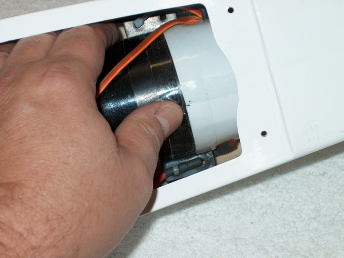
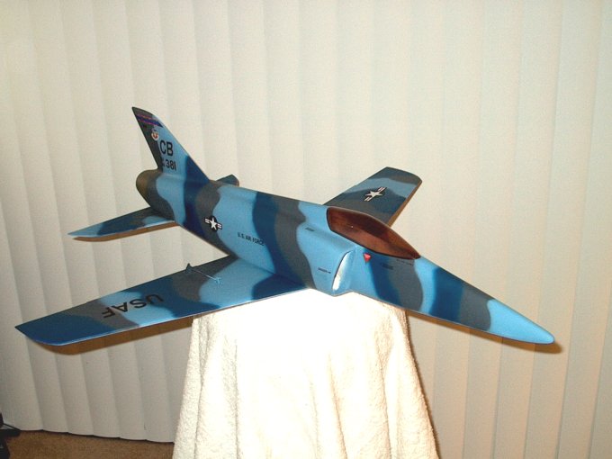
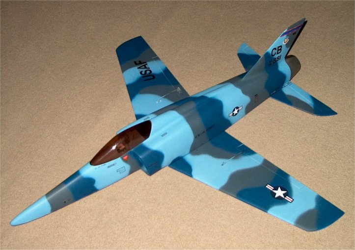
78 - The fan fits inside now and very
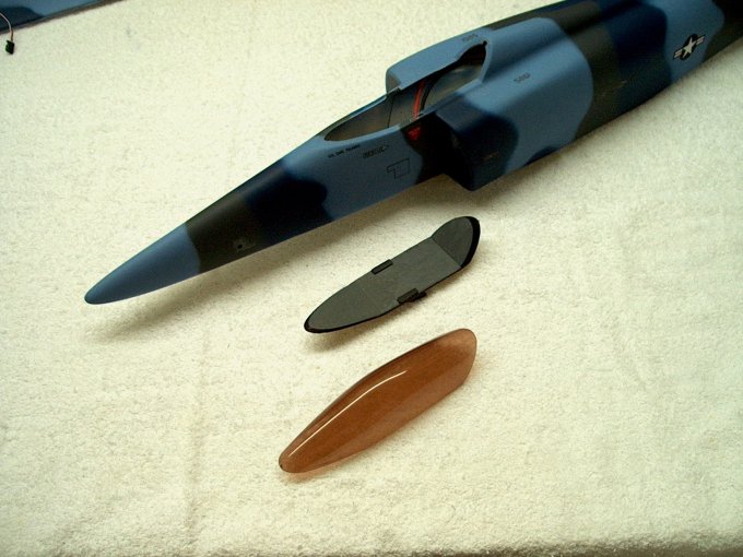
little saddle was removed. | |
79 - Fan shown completely inside of the
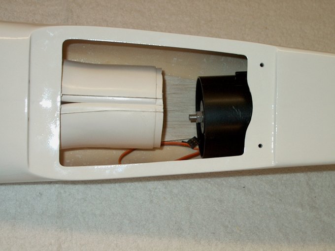
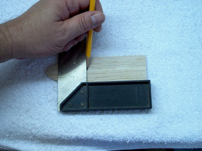
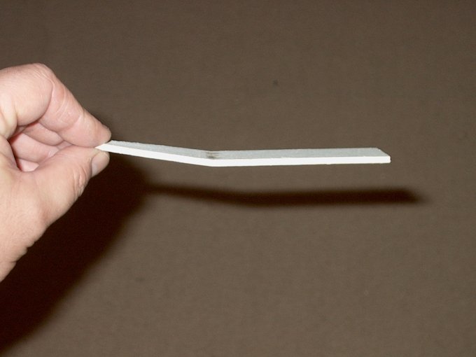
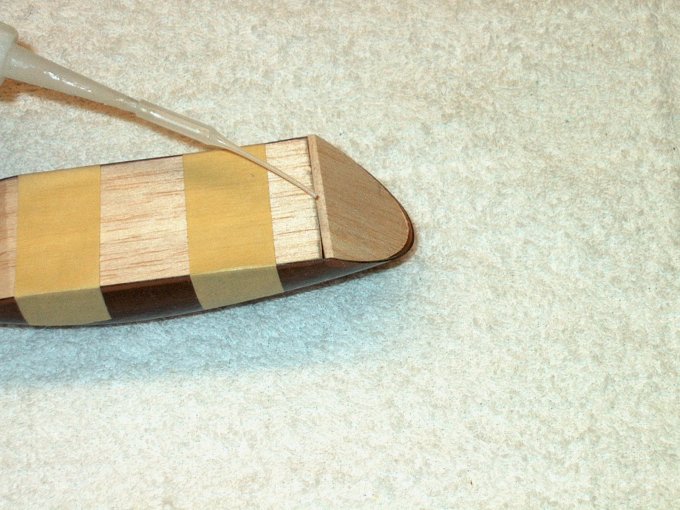
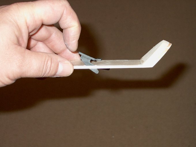
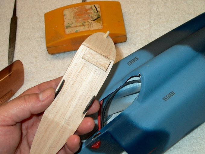
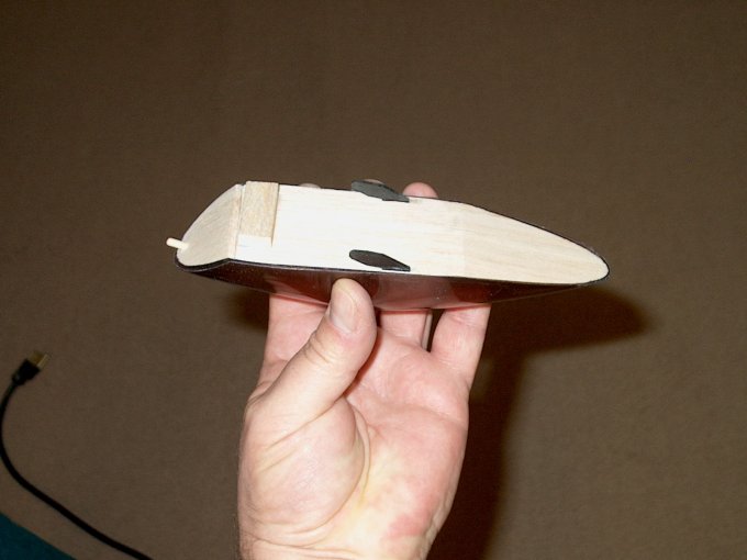
fuselage. | |
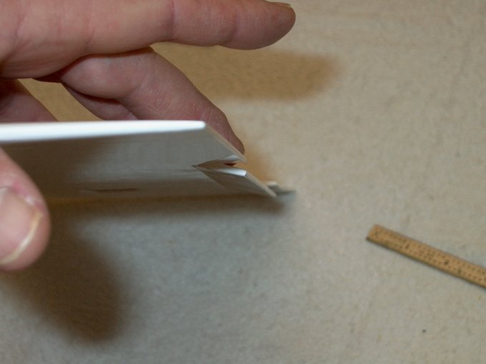
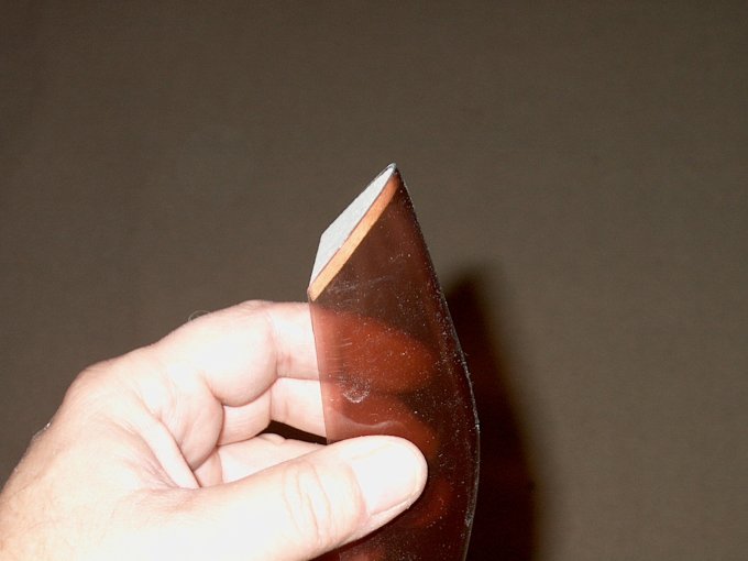
80 - Note the ends were also rounded,
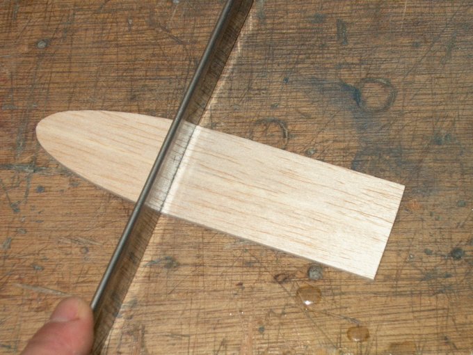
which "relieves" them and helps prevent cracking.
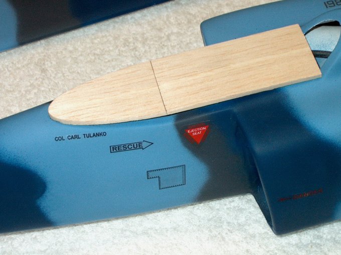
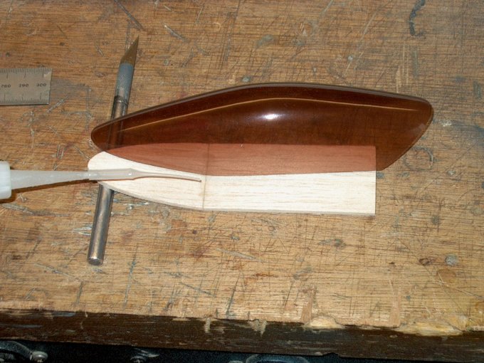
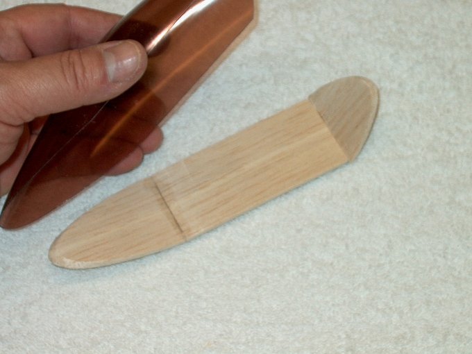
| |
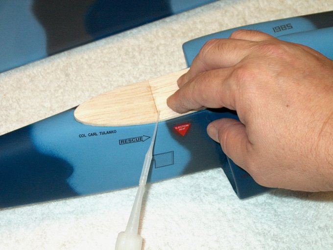
81 - A Dremel with a sanding drum was used
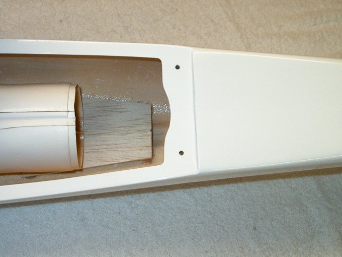
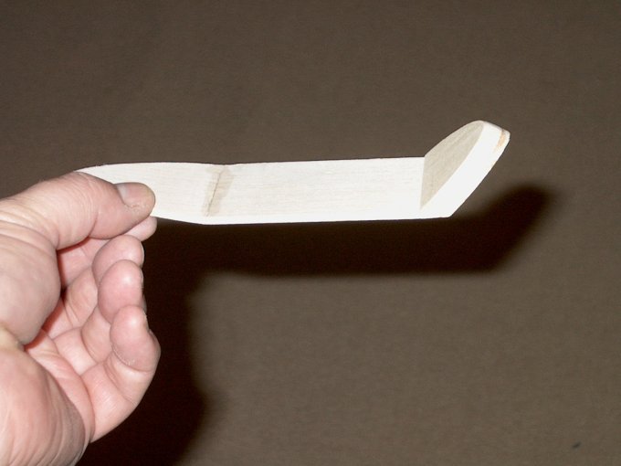
to even up the ducting. | |
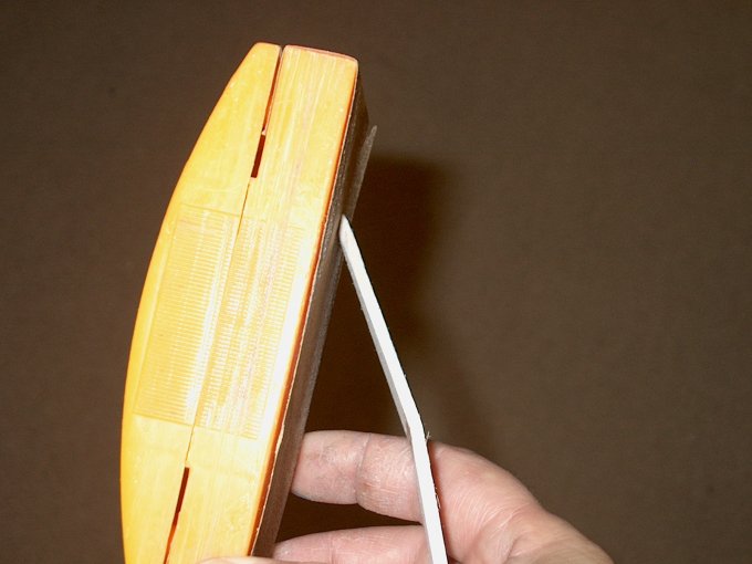
82 - NOTE: If you are not painting your
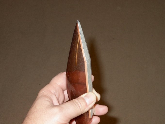
model, skip the next six steps. 320 Grit wet/dry sandpaper was
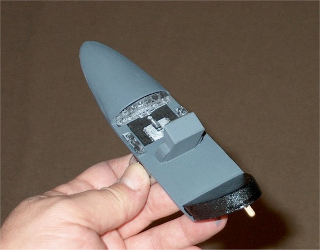
used to flatten the surface of the fuselage for good paint
adhesion. | |
83 - Once sanded, wash down the area to
remove any excess paint. | |
84 - The surface should still appear
white, but "flattened" in color. | |
85 - 320 grit sandpaper was used to "dry
sand" the horizontal stab. | |
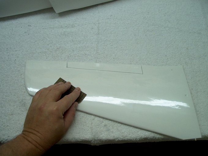
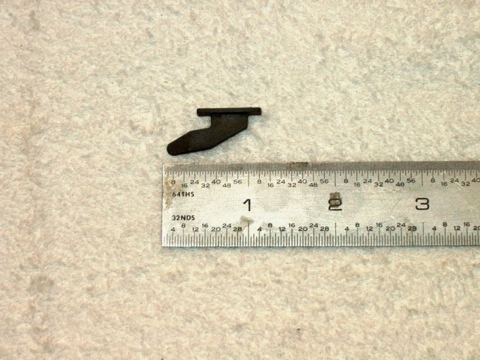
86 - The wings were also sanded to allow
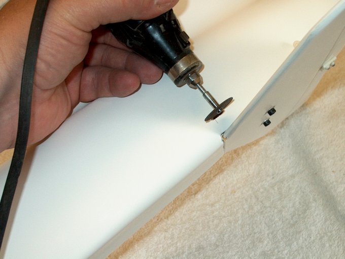
for good paint adhesion. | |
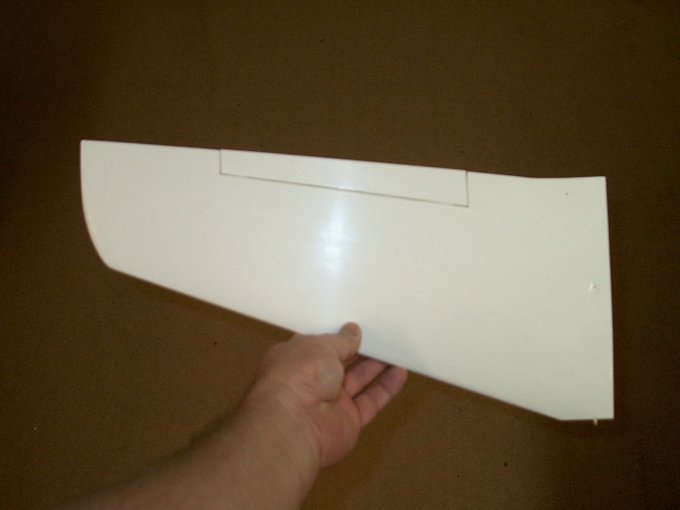
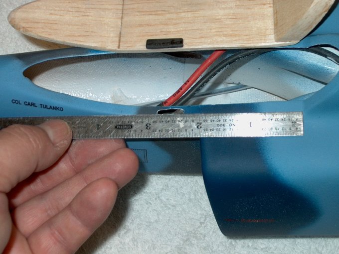
87 - All surfaces washed and shown now
with that "flat white" look. | |
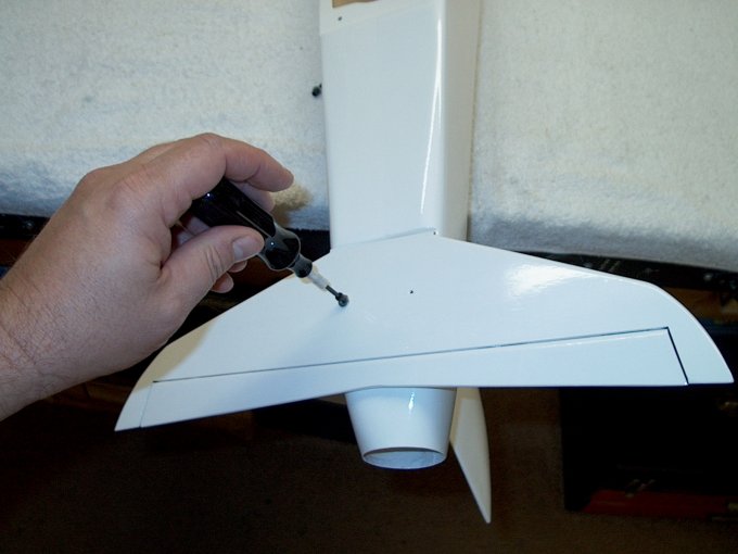
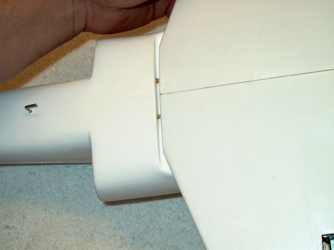
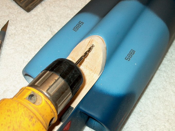
88 - The tail assembly is temporarily
connected to the fuselage using two of the bolts and small
washer provided. | |
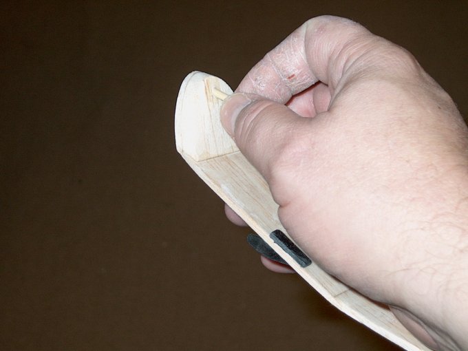
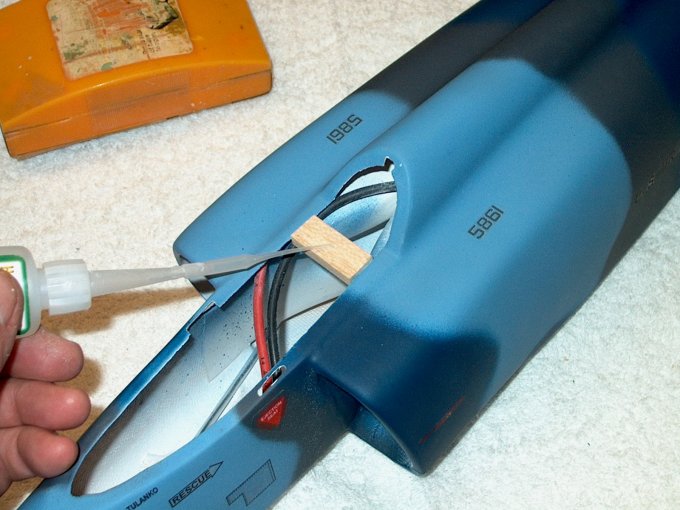
89 - The tail shown installed and flush
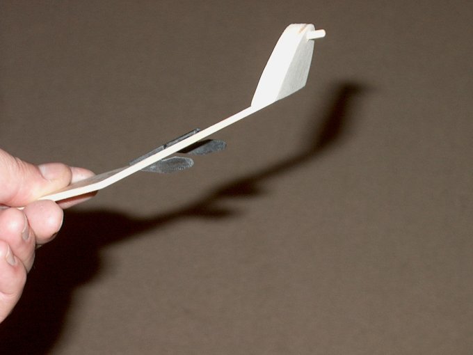
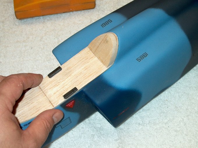
with the fuse at the top. | |
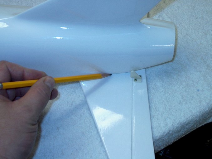
90 - The elevator horn was placed on the
elevator with its center 1/4" away from the fuselage side to
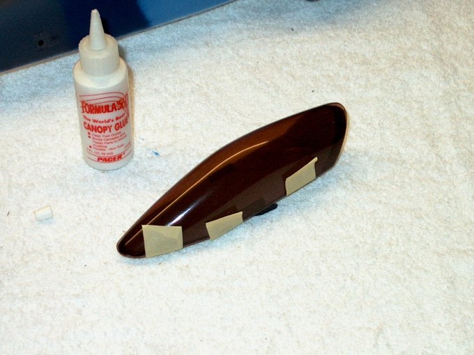
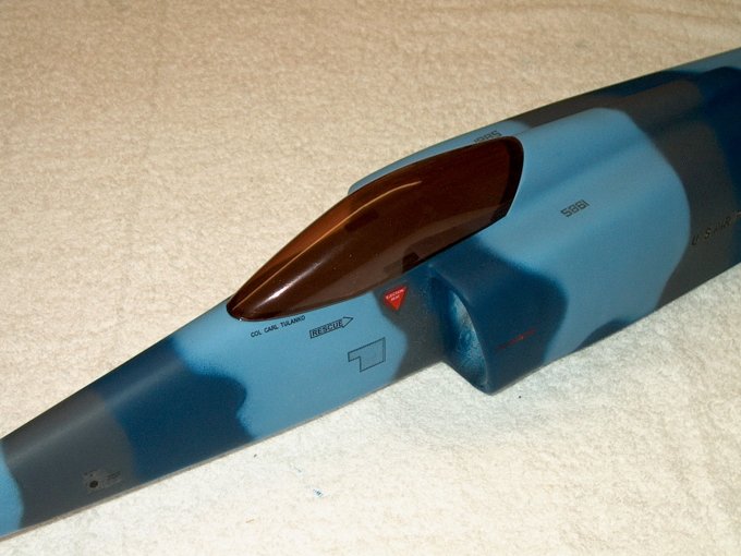
allow for clevis clearance. | |
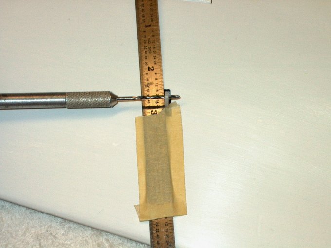
91 - The elevator was drilled using a pin
vise. | |
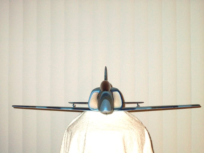
92 - The bolts supplied in the kit are
used to attach the horn to the elevator.
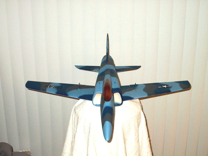
| |
93 - Excess bolt length is cut flush to
the horn retainer. | |
94 - A drop of medium CA is applied to the
top of each bolt end. | |
95 - Hinge shown installed.
| |
96 - Rod supplied in the kit was tried but
it was too loose in the horn. | |
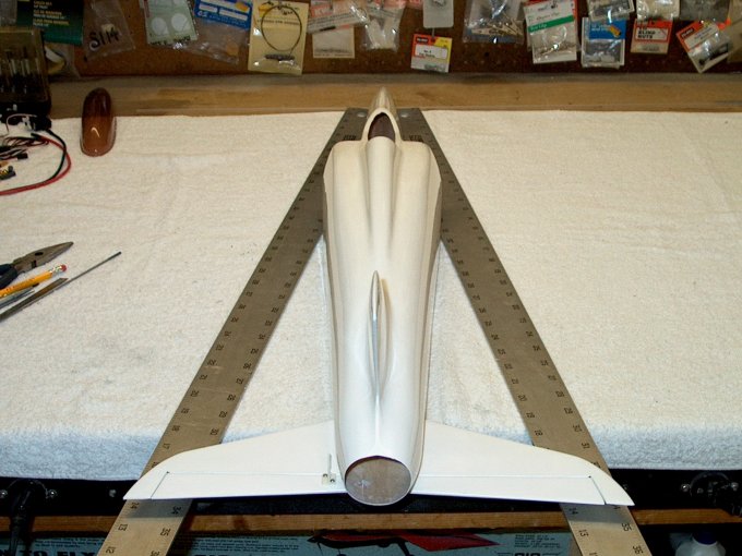
97 - Preliminary check of tail alignment.
It appears that mounting the tail and pushing it forward flush
to the fuselage makes for a worry free install with no check
needed. | |
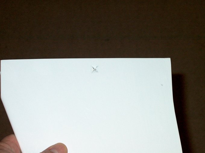
98 - Stab being marked for permanent
installation. | |
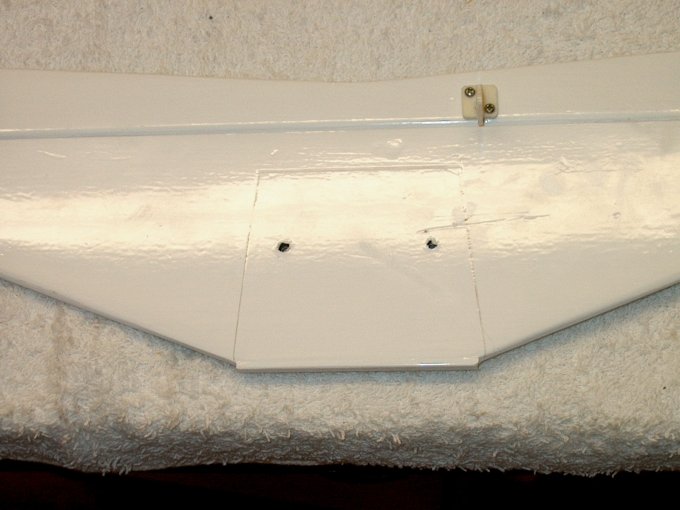
99 - Stab marks shown.
| |
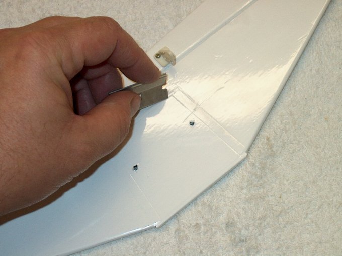
100 - Plastic covering from the inside
area was removed so that stab could be epoxied to the
fuselage. | |
101 - Plastic covering shown being
removed. | |
102 - Stab prepped for final install. Make
sure you remove the top area and not the bottom.
| |
103 - Epoxy applied to stab area. The stab
needs to be epoxied as the bolts cannot be tightened without
crushing the balsa. You may try cutting the bolt area out and
replacing with a plywood plank. This would allow for a "bolt
on" stab. | |
104 - The fuselage area was roughed up
with 60 grit sandpaper and then both surfaces had epoxy
applied. | |
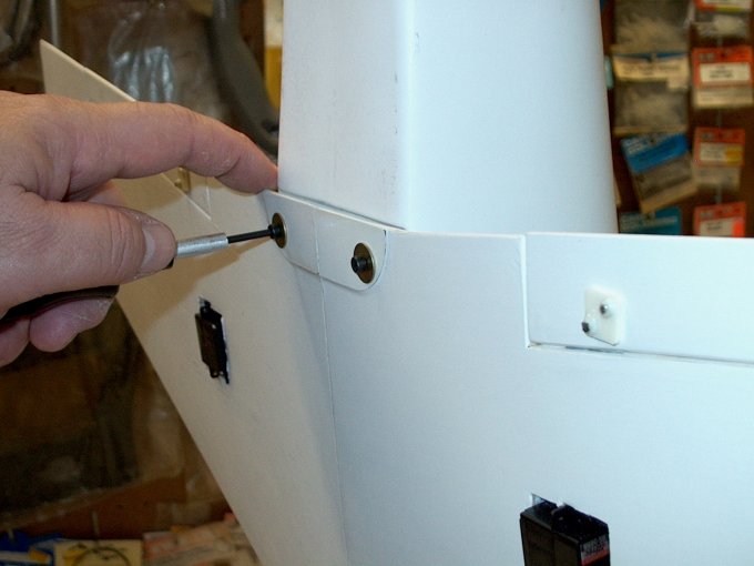
105 - The stab was bolted permanently in
place with the leading edge pushed flush against the
fuselage. | |
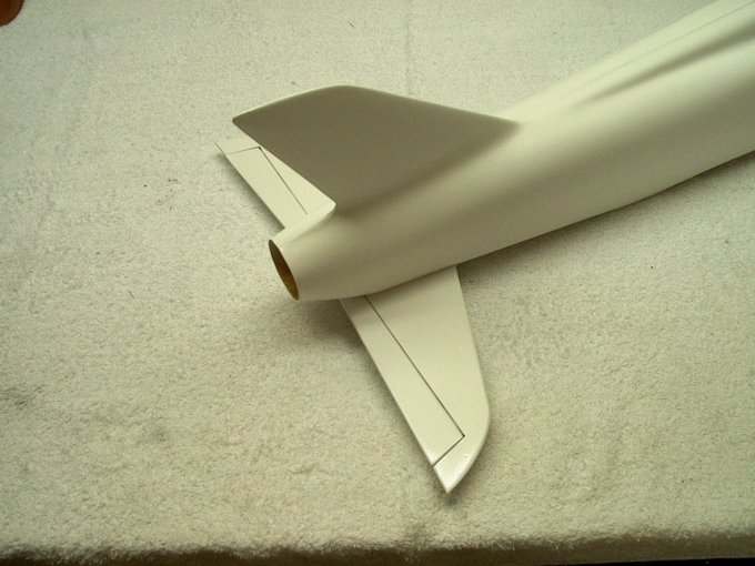
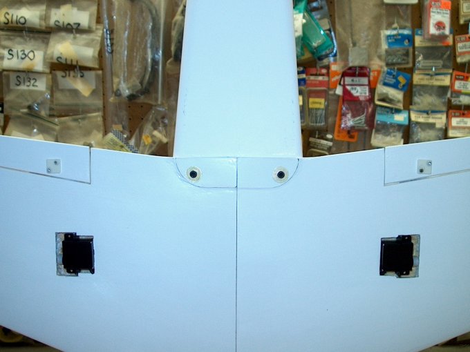
106 - Horizontal stab installation
completed. | |
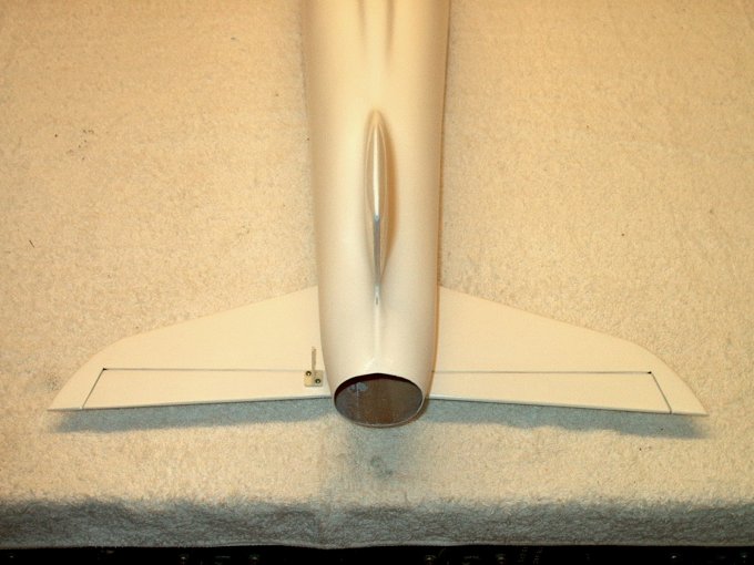
107 - Stab installed, rear view showing
horn location. | |
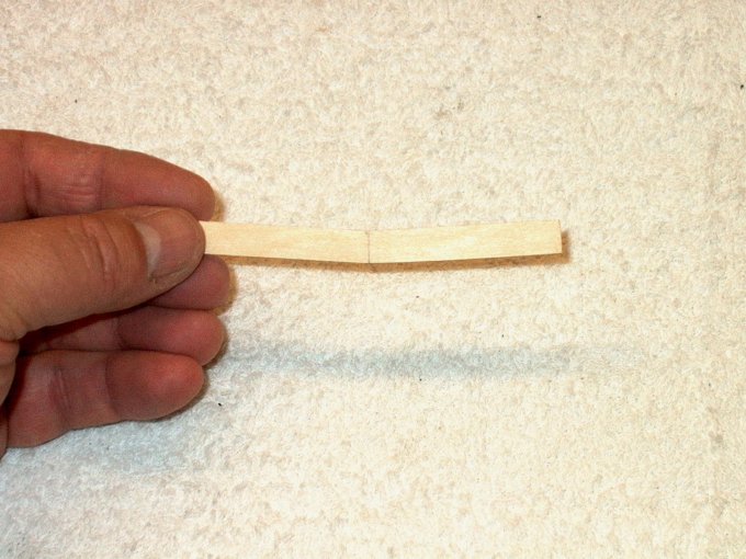
108 - Main wing spar, ready to install. I
drew a center line on it for reference.
| |
109 - Wing components ready to go.
| |
110 - Root spar drilled with a 3/32 bit to
add more strength once glued. | |
111 - Epoxy added to main spar and root,
then spar is installed. | |
112 - Spar inserted up to center line.
| |
113 - 15 Minute Epoxy added to other wing
root and exposed spar. | |
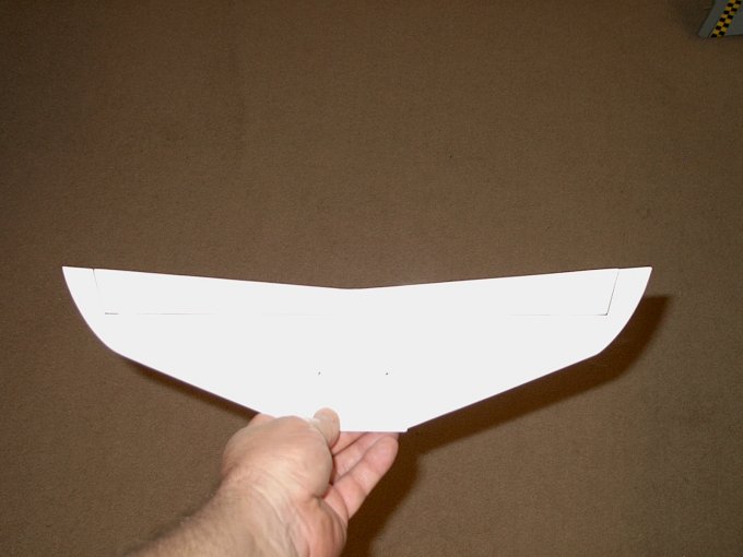
114 - Wing halves joined and excess epoxy
cleaned up with denatured alcohol. | |
115 - Wing assembly laid flush on table to
keep it aligned. Both halves were pressed down on the table to
make their joint even, so incidence would be aligned.
| |
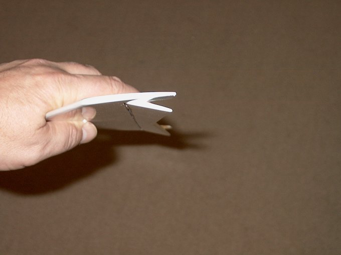
116 - Wing tip propped up at proper
dihedral while epoxy sets. | |
117 - Final fan assembly... cleaning up
the wiring with ties. | |
118 - Rear view of wiring tied
down. | |
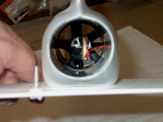
119 - Final installation of the fan
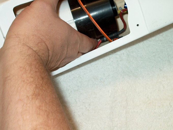
assembly. | |
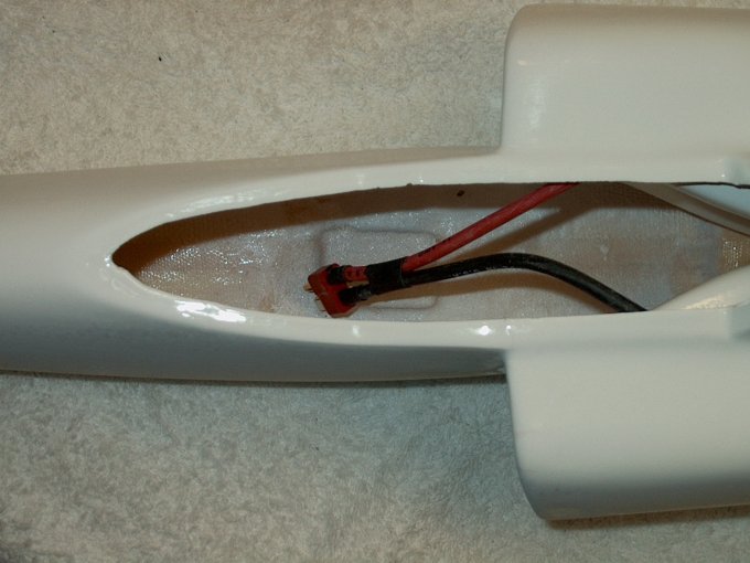
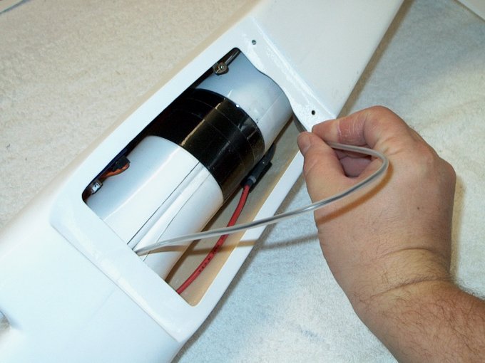
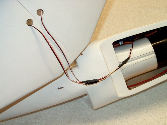
120 - The power wire was pulled across the
top of the duct (inverted, so it's seen on the bottom.) This
routed it right into the cockpit bay.
| |
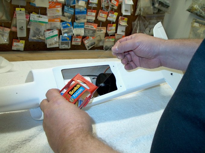
121 - Heavy duty packing tape used to
attach fan to duct. | |
122 - Tape applied on one half from the
opening. | |
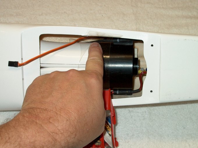
123 - Tape pushed down to inside
area. | |
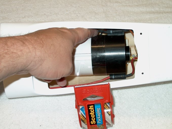
124 - Tape trimmed and other end worked
around. | |
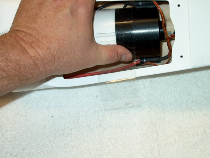
125 - End is tucked under the
bottom. | |
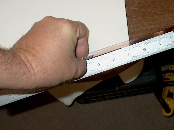
126 - A ruler taped to a stick was used to
push the remaining tape around the top of the duct.
| |
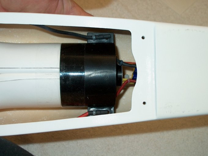
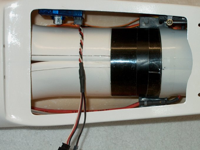
127 - Fan assembly installed, showing ESC
that will reside in the duct. | |
128 - Top view showing fan connected to
ductwork. | |
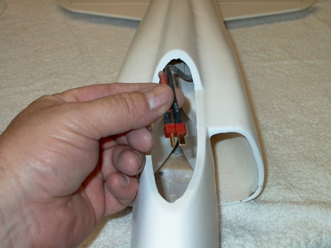
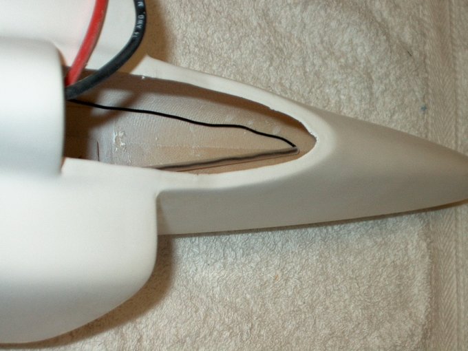
129 - Battery wires that were routed into
the cockpit compartment. | |
130 - Battery harness shown with enough
length to reach anywhere in the compartment.
| |
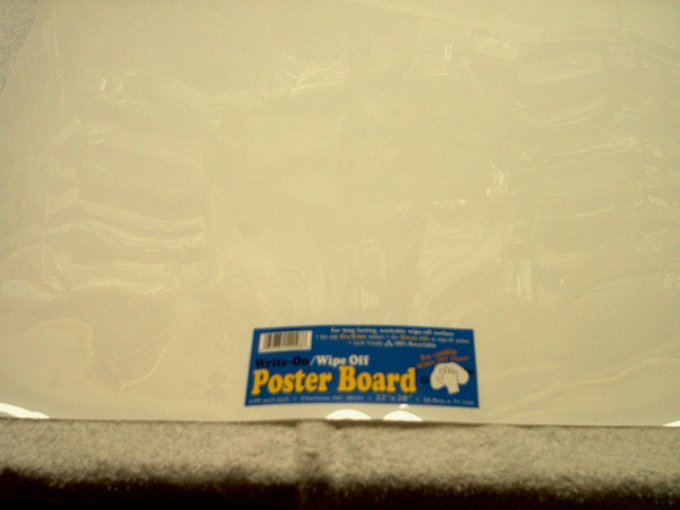
131 - A piece of poster board purchased at
a craft store will be sued for the final ductwork. NOTE:
Poster board cardboard is supplied with the kit.
| |
132 - Wiring removed from battery leads
and routed inside fan so the exhaust duct can be
fitted. | |
133 - Initial piece of 10" x 15" cut from
sheet. | |
134 - Shape was rough cut...
| |
135 - ... then fit to rear of fan. This
will take a while to fit and was a bit challenging due to the
taper in the duct, so just take your time.
| |
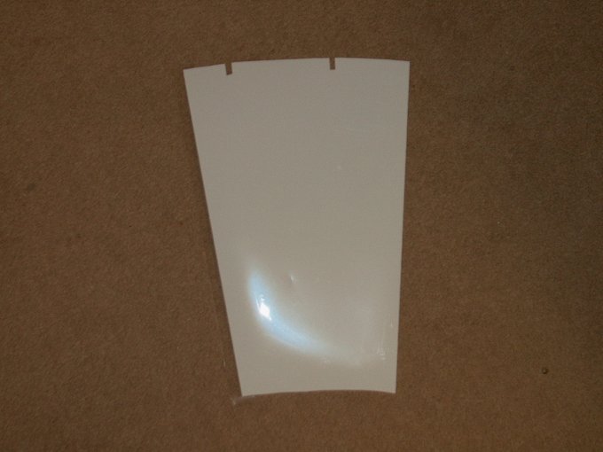
136 - Final sheet ready for assembly. I
used the first sheet to mark up and abuse, then cut a final
pattern from the first sheet, that way there were no wrinkles
in the duct. | |
137 - The same heavy duty clear packing
tape that was used to mount the fan was used to roll the
tube. | |
138 - A piece of aluminum tube was used to
cut exit holes fro the ESC wires. | |
139 - Holes cut, tube ready to
install. | |
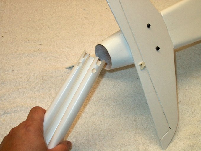
140 - Duct tube folded in half for
installation, then inserted from the rear.
| |
141 - ESC wires routed through the punched
holes. | |
142 - Packing tape used to hold the
exhaust duct in place. | |
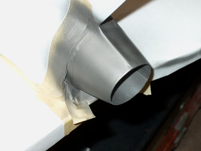
143 - Exhaust duct installed
| |
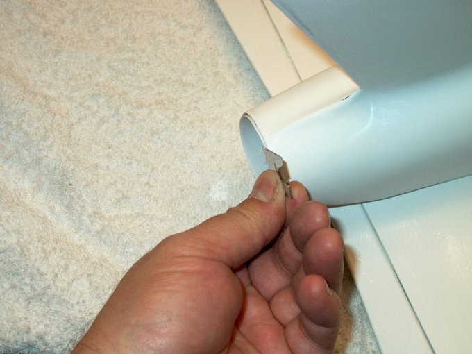
144 - End of exhaust area trimmed even
with the tail cone. | |
145 - Exhaust finished.
| |
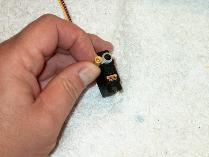
146 - The servo horn was installed and the
EZ Connector supplied with the model was installed in the
outer horn hole. The hole needed to be enlarged for the
threads. Make sure it turns freely once installed and use
Loktite on the threads. | |
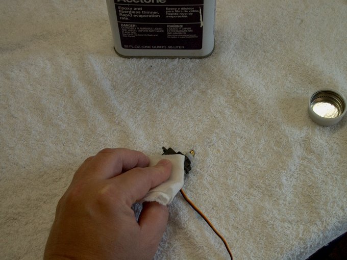
147 - Servo side is cleaned with
acetone. | |
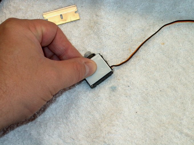
148 - Mounting tape is applied to the
servo side. | |
149 - Servo is then installed on the
sidewall. Make sure you clean this area with acetone before
mounting the servo. | |
150 - Elevator servo installation
completed. Note that the washers supplied with the gold
connector were not used as they would have caused binding on
the servo arm when rotating. | |
151 - Hole is opened on side of fuselage
for the elevator control rod. | |
152 - Hole shown below... NOTE: It was
extended to 7/8" in length later on during the build. It is
3/32" wide and the bottom is 3/8" above the horizontal
stab. | |
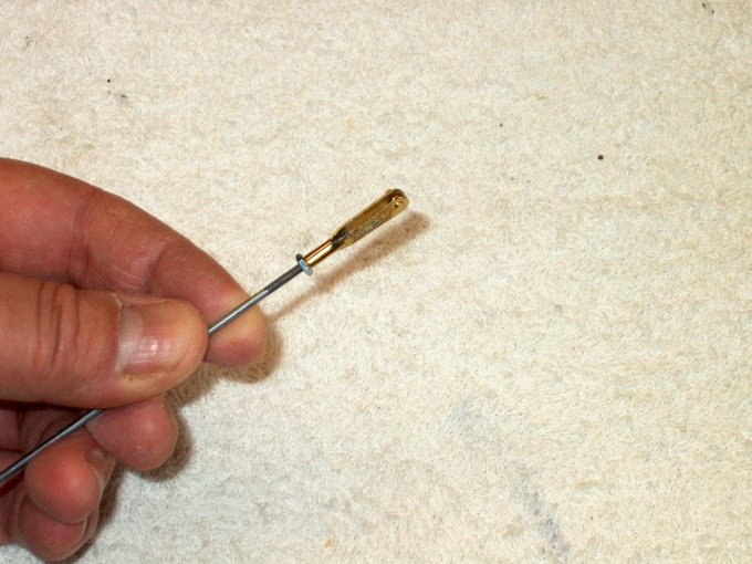
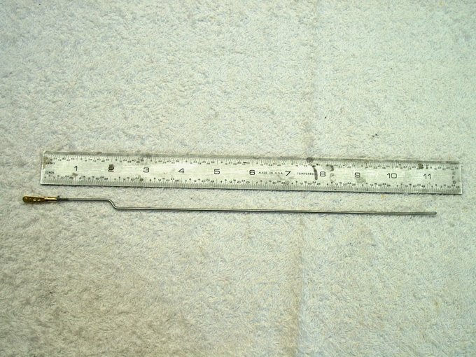
153 - Clevis installed on a new 2-56 x 12"
long pushrod. | |
154 - Rod bent and shaped for
opening. | |
155 - Picture shows rod shape and points
to bend. | |
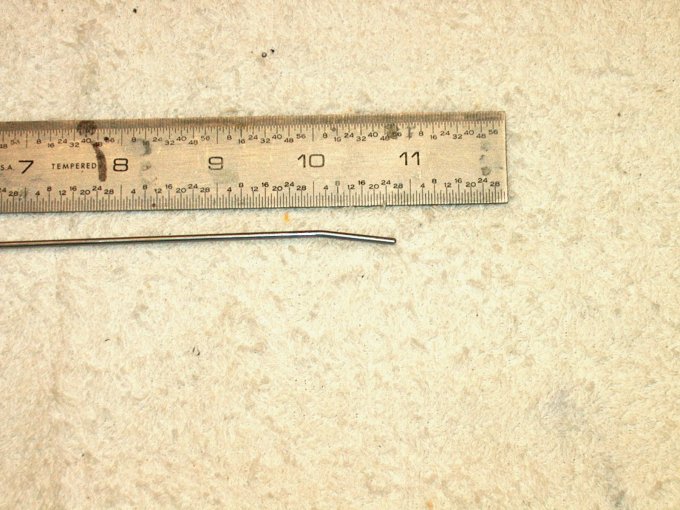
156 - End was slightly bent to align with
the EZ Connector for the servo. | |
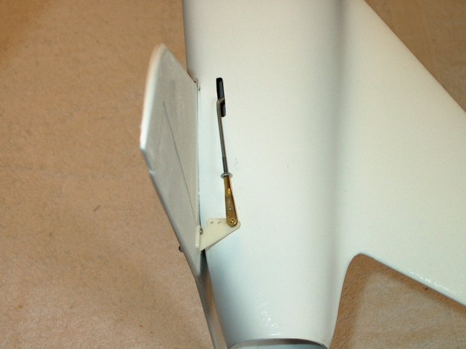
157 - Rod final installation.
| |
158 - Pushrod installed.
| |
159 - Loktite added to EZ Connector set
screw. | |
160 - Turn on your radio, then center the
servo, center the elevator and tighten the screw.
| |
161 - Inside of fuselage cleaned for
receiver location. | |
162 - Original receiver installed in the
following location. | |
163 - Originally the antenna was installed
in a tube and installed partially up in the nose and the rest
of the antenna out the back of the fuse. This was later found
to produce glitching and changed. NOTE: If you decide to
install your antenna this way you must do a range check. We do
not recommend you install your antenna this particular way for
the Sniper. | |
164 - Do not use the antenna tube if you
have glitching problems and always range check
| |
165 - The rest of the antenna out the back
of the fuse. This was later found to produce glitching and
changed. | |
166 - Tube shown in place...
| |
167 - ...and epoxied to the side of the
fuselage | |
168 - Y-Connector added for aileron servo
wires... build completed. | |
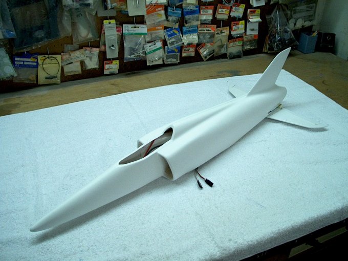
169 - Basic fuselage assembly
completed. | |
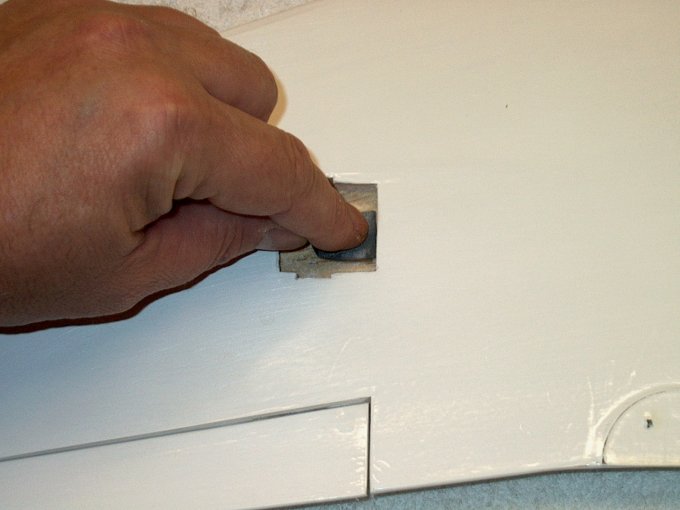
170 - Aileron servo area was soaked with
thin CA to strengthen, then sanded smooth.
| |
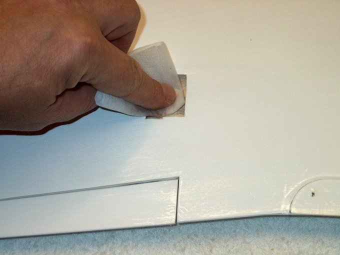
171 - Area cleaned with denatured
alcohol. | |
172 - Servo temporarily fit to cut horn
slot. | |
173 - Servo wire holes opened up in the
wing. | |
174 - Servo plug removed and wires run
through pre-cut channel. | |
175 - Wire pulled throgh from aileron
servo bay. | |
176 - Plug re-installed on servo
wires. | |
177 - Servo arm installed.
| |
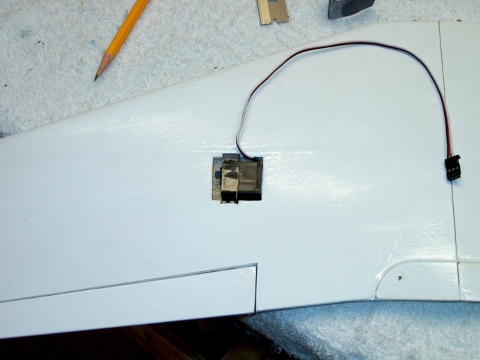
178 - Servo cleaned with acetone and
double sided tape added. | |
179 - Servos installed in both
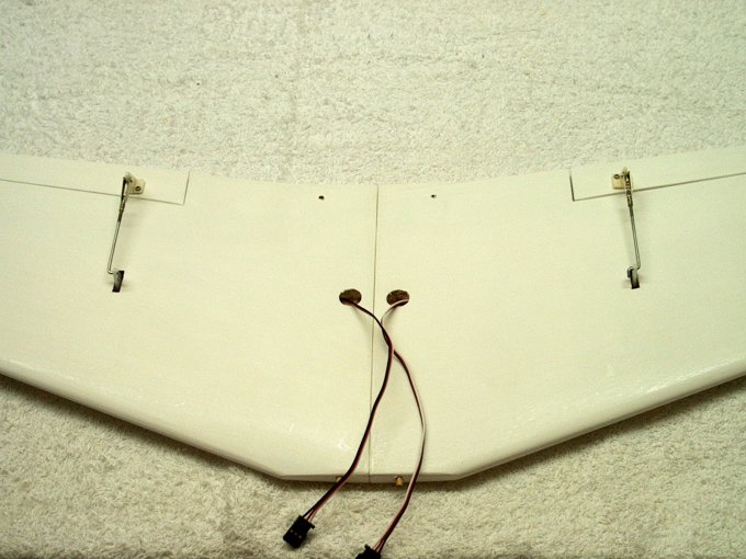
wings. | |
180 - Aileron wires exiting wing.
| |
181 - Shaping the aileron pushrod. A
Z-bend was used on one end. | |
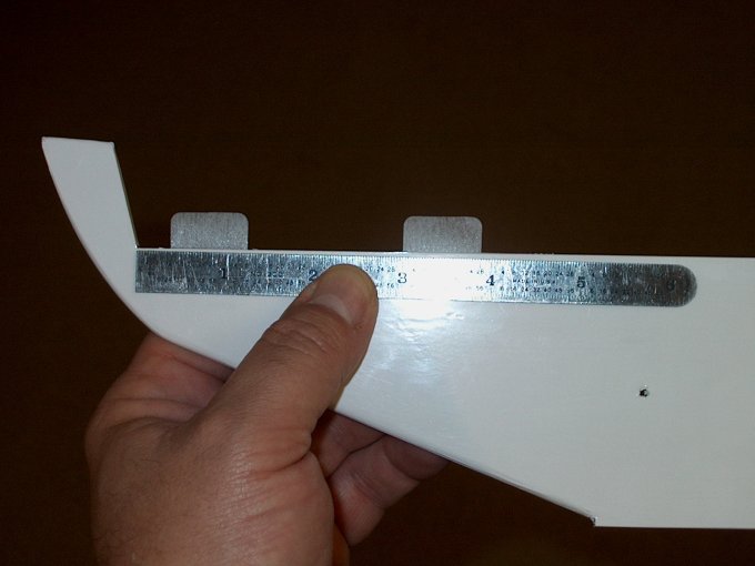
182 - A ruler was used to align the
pushrod while the aileron horn was installed.
| |
183 - Horn bolts were trimmed
flush. | |
184 - Left aileron servo and pushrod
assembly completed. | |
185 - Installing the right side pushrod.
Note the horn did need to be drilled to accept the
pushrod. | |
186 - Aileron control completed.
| |
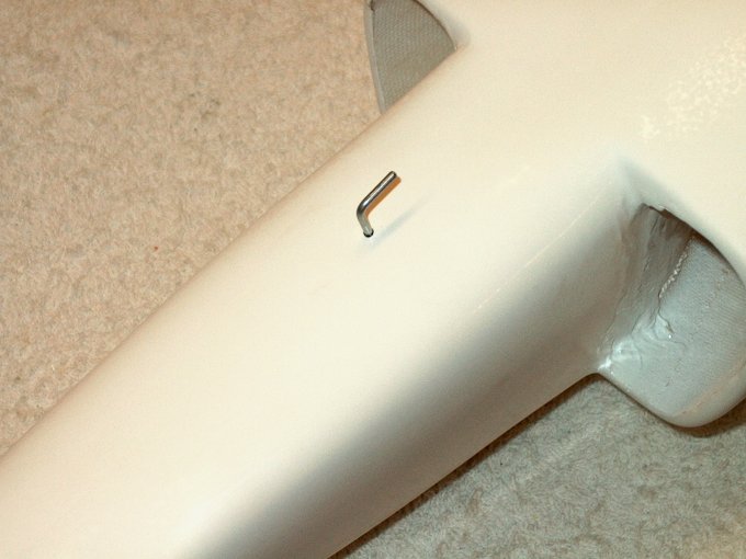
187 - Tow hook made from extra rod and
installed in pre-drilled location. | |
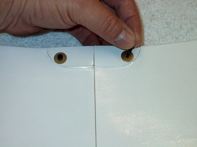
188 - Wing bolts installed.
| |
189 - Aileron servos hooked up to the
receiver. | |
190 - Wing leading edge dowels plugged
into front of fuselage. | |
191 - Wing mounted to fuselage.
| |
192 - Wing assembled.
| |
193 - Cutting out the canopy. It was
scored with a razor. | |
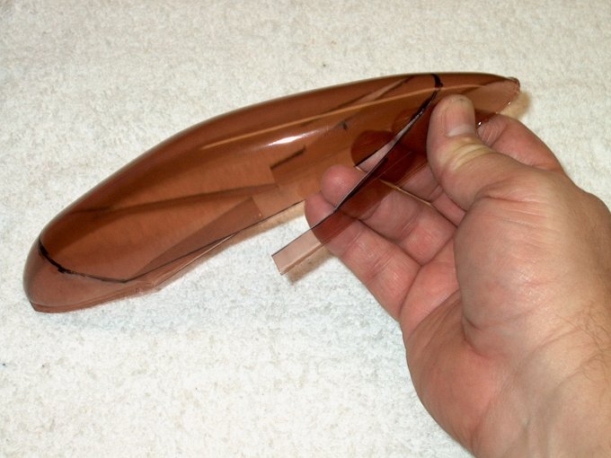
194 - Canopy cut out along score
marks. | |
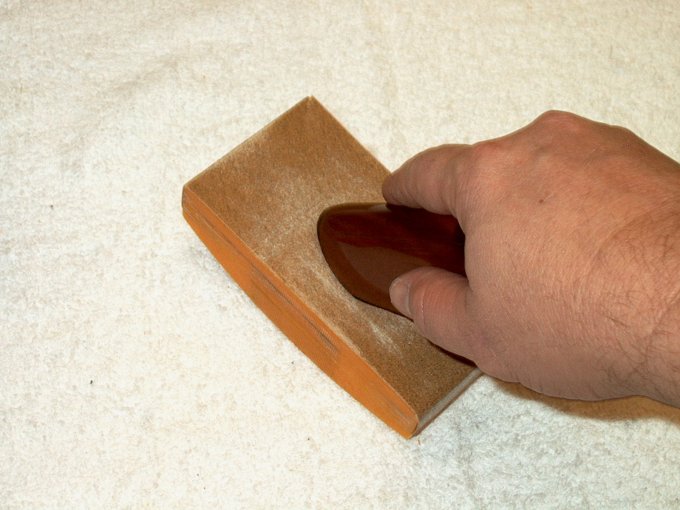
195 - Canopy sanded and shaped.
| |
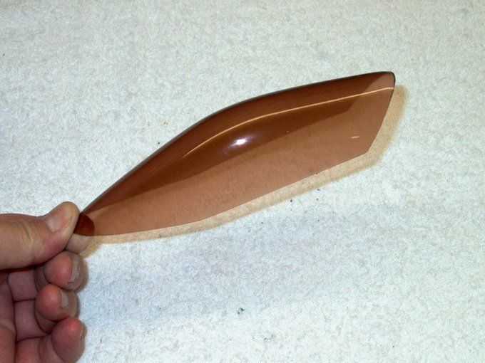
196 - Canopy finished and ready to
install. | |
197 - Canopy placed on fuselage for size.
It will be permanently mounted later.
| |
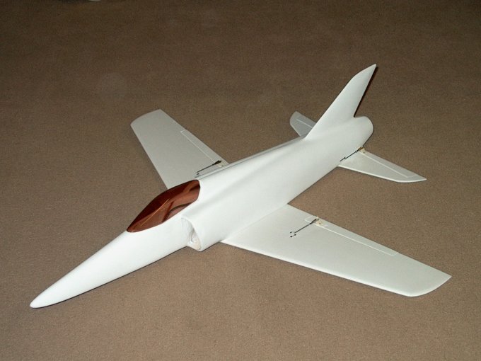
198 - HET-RC Sniper basic construction
completed. | |
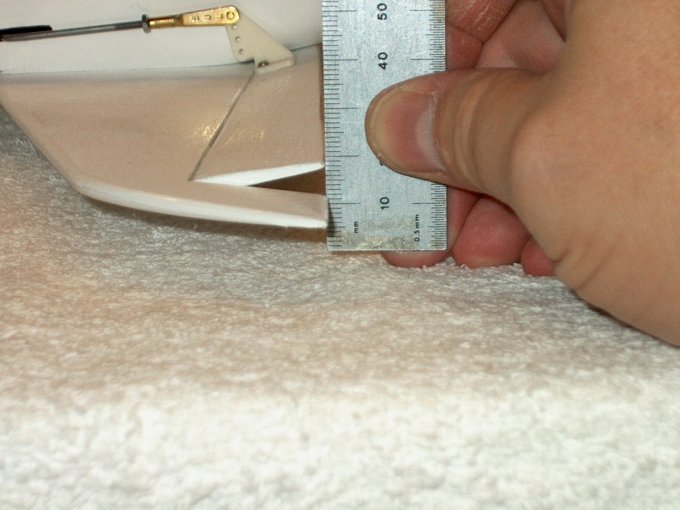
199 - Elevator throws are as follows: High
Rates: UP 8mm / DOWN 6mm Low Rates: UP 5.5mm / DOWN 4mm
| |
200 - Aileron Throws: High Rates:
LEFT/RIGHT 8mm / DOWN 6mm Low Rates: LEFT/RIGHT 6mm / DOWN 4mm
| |
201 - The C/G (Center of Gravity) point is
90mm from the base of the leading edge of the wing. You may
opt to move it forward or back, but based on our findings 90mm
is the best starting point. | |
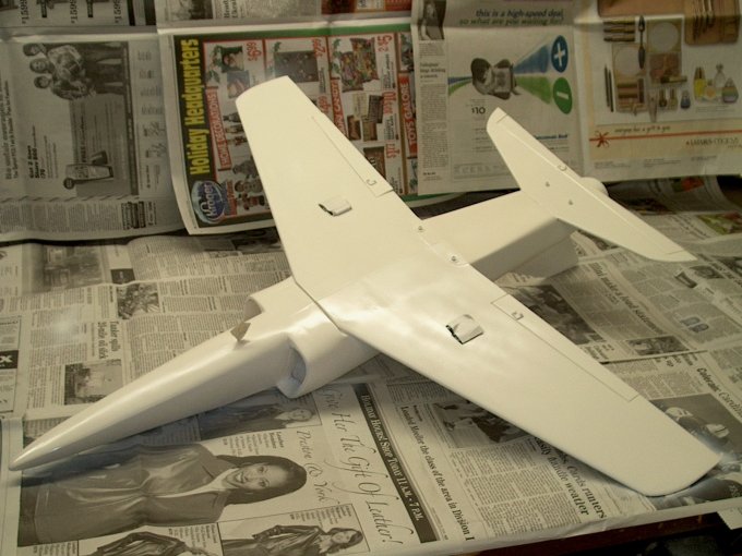
202 - Bottom painted flat white.
| |
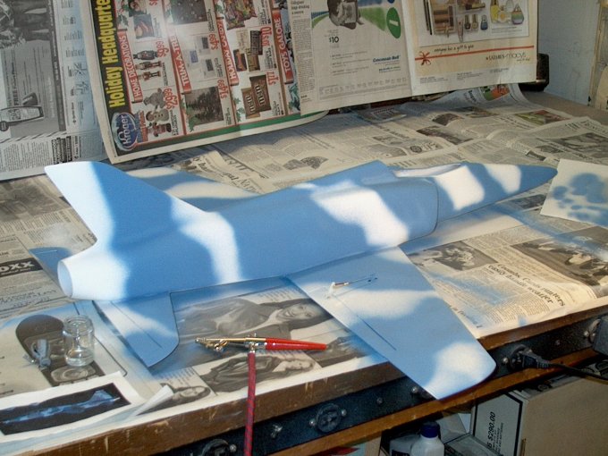
203 - Started the top side using flat
light sky blue. | |
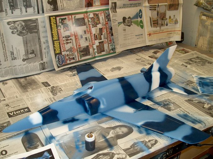
204 - Second color added... dark
blue. | |
205 - Model colors finished.
| |
206 - Painted the tail cone with "Burnt
Metal". | |
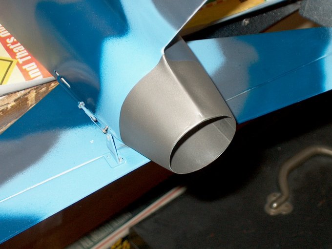
207 - Tail cone finished.
| |
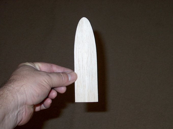
208 - Canopy /Cockpit Build: NOTE: If you
are going to place the batteries in the wing saddle area, the
canopy can be simply glued to the fuselage with canopy glue.
The following steps will show how to build a simple removable
canopy. A base plate was traced onto 1/8" balsa.
| |
209 - A center line was drawn where the
canopy bend is located. | |
210 - A saw was used to cut a "bend slot"
... do not cut all the way through.
| |
211 - Balsa cockpit base placed on the
fuselage. | |
212 - Cockpit held down in place while
using thin CA to glue the joint. | |
213 - Cockpit angle finished.
| |
214 - The seam was filled all the way
across and the angle was measured to make sure it fit the
cockpit. | |
215 - Beveling the front edge.
| |
216 - Cockpit plate fit to the
canopy. | |
217 - Drawing a back plate.
| |
218 - Plate cut from 1/8" ply.
| |
219 - Plate beveled and checked for
fit. | |
220 - Back plate pressed into place at
correct angle. | |
221 - Back plate glued to cockpit.
| |
222 - Plate glued then canopy painted with
thin CA. | |
223 - 1/4" Think piece of balsa added to
rear. | |
224 - I used a Bob Violett canopy mount,
but you could also make them from 3/32" ply using the shape
below as a reference. | |
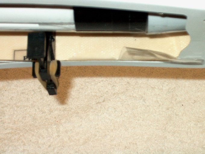
225 - Canopy plate slotted. Fuselage
slotted with a Dremel cutting wheel.
| |
226 - Canopy mount installed.
| |
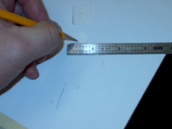
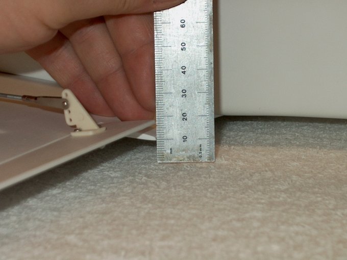
227 - Measurement showing location of the
slots. | |
228 - Canopy mounted and held in place,
then drill used to bore through the canopy and
fuselage. | |
229 - Installing an alignment pin from
1/8" dowel. | |
230 - Pin installed.
| |
231 - A piece of 1/4" x 1/2" balsa cut and
fit to opening below, lightly wedged in place. CA applied to
the top only. | |
232 - Canopy set in place, lifting the
rear, pushing all the way back, then dropping the rear on the
balsa piece from the previous step.
| |
233 - Dropping rear forced the piece to
glue on canopy for a perfect fit. This piece of balsa will
insure the canopy will not twist under stress of
flight. | |
234 - Cockpit painted.
| |
246 - Cockpit detailing was done to model
an F-5 | |
235 - Canopy Glue used to mount the canopy
to the cockpit. Tape is used to hold it in place until it
dries. | |
236 - Cockpit plate installed on
canopy. | |
237 - Canopy installation completed. It's
a simple way to mount it and the canopy should not come off
during flight as it needs to move forward and up to be
removed. | |
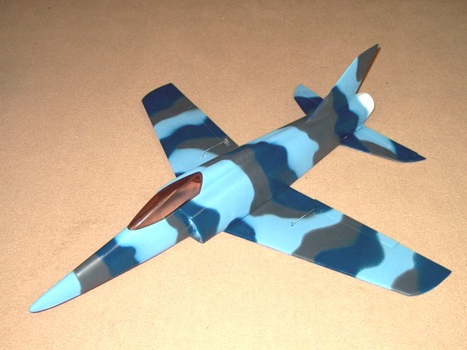
238 - HET-RC Super Sniper ARF Model
finished (FRONT VIEW) | |
239 - (FRONT / TOP VIEW)
| |
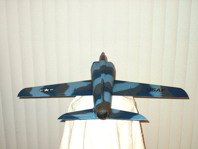
240 - (REAR VIEW)
| |
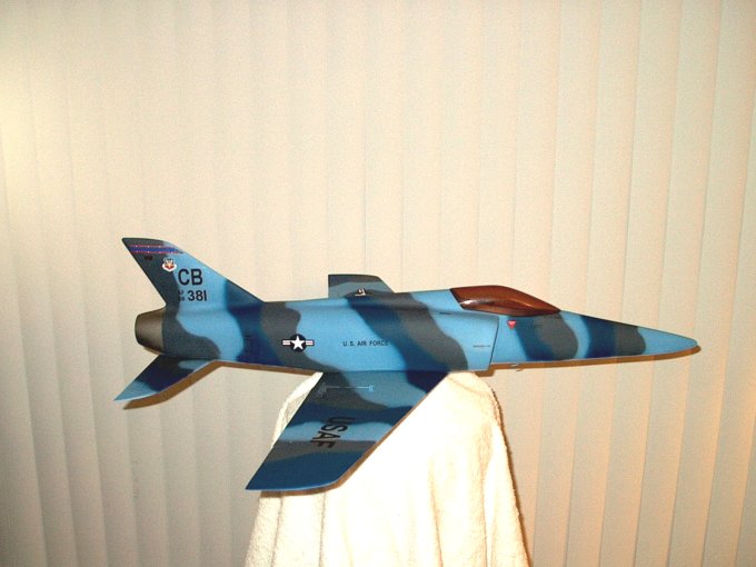
241 - (RIGHT SIDE)
| |
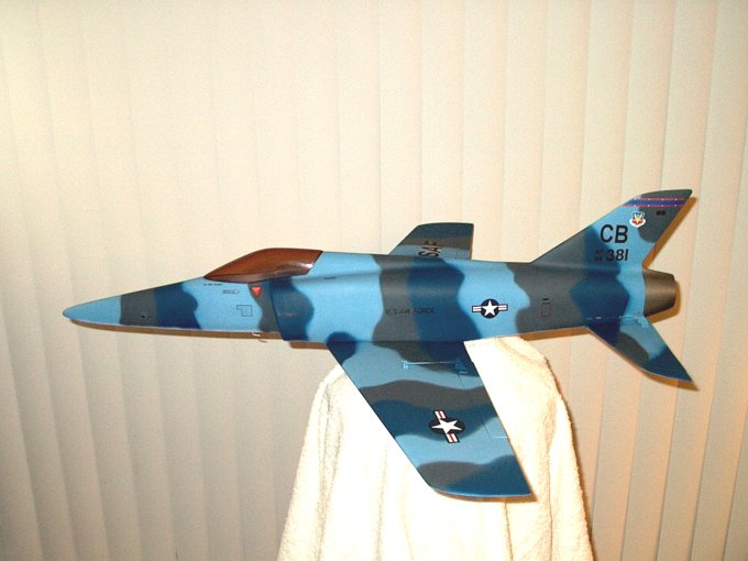
242 - (LEFT SIDE)
| |
243 - (NOSE PROFILE)
| |
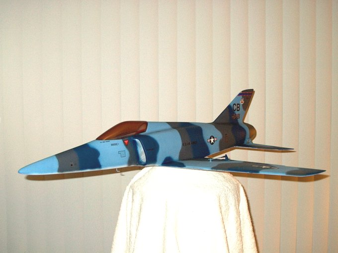
244 - (RIGHT ANGLED VIEW)
| |
245 - (TOP VIEW)
| |
247 - The completed HET-RC Sniper from
Warbird-RC | |

This Website and all documents herin are Copyright © 2012 www.scalerocketry.com -
All rights reserved.
| |