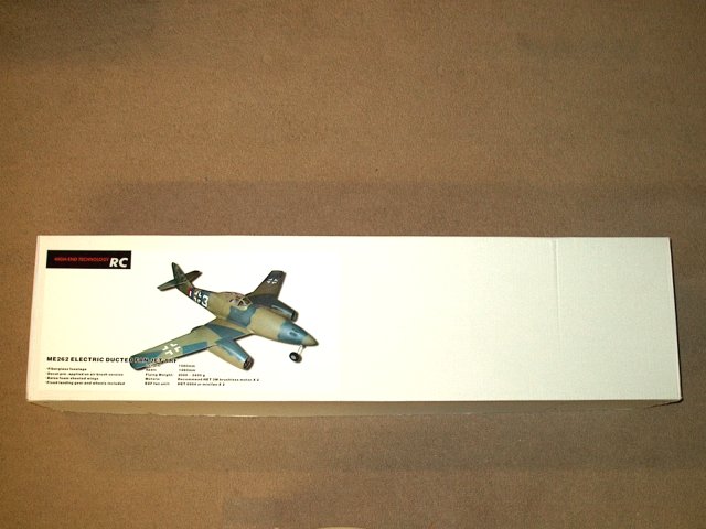
The HET-RC ME-262 Twin Minifan EDF jet as
it comes from Markos at Warbirds-RC
| |
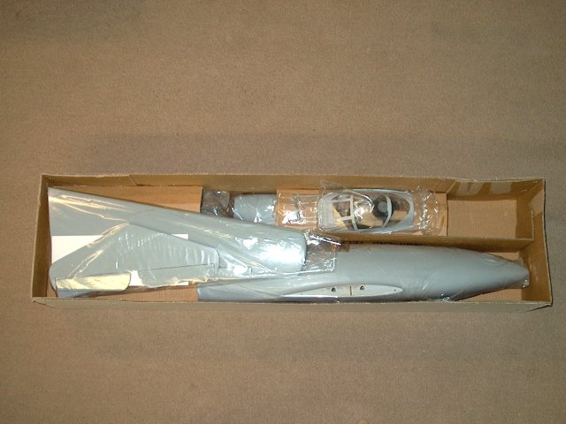
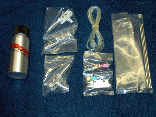
Opening the box reveals well packed
contents | |
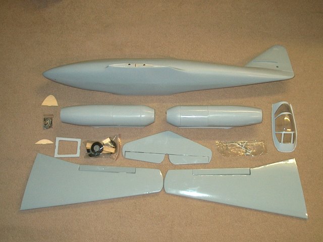
All the parts shown are included in the
kit, even fixed landing gear | |
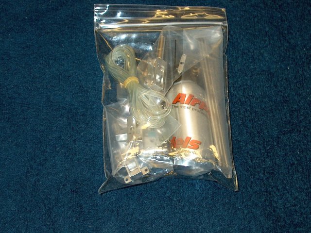
This kit will be retrofitted with some of
the "New" RA-260 Retracts from Airpower and Warbirds-RC
| |
Opening the main bag reveals all the
components necessary to get these air retracts flying
| |
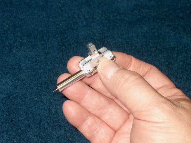
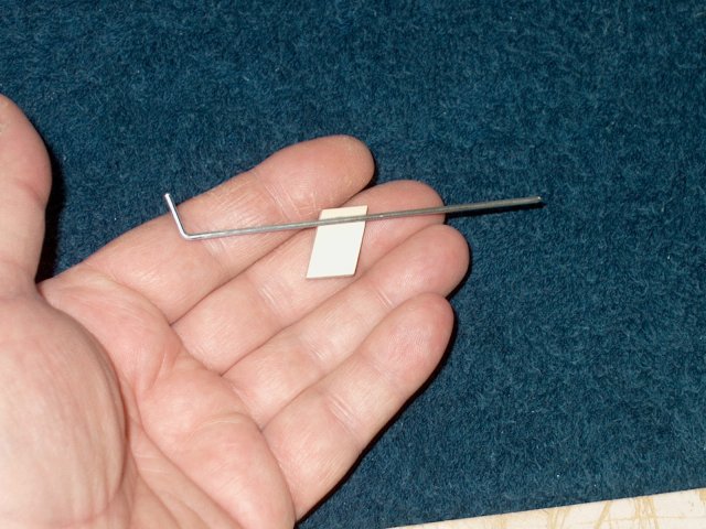
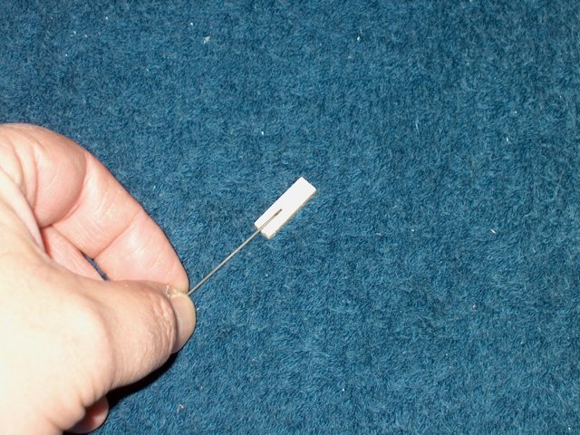
The retract units themselves are very
small, however, they are stout. The units are made from very
thick aluminum alloy and are much sturdier than other brands
of retracts we have used in the past. They also come with 1/8"
gear wire | |
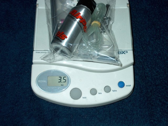
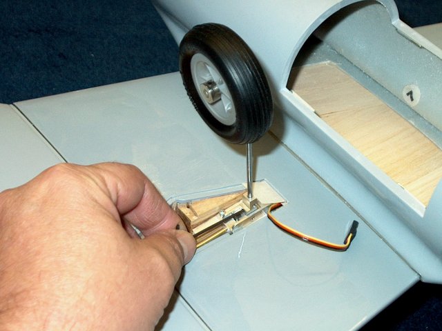
The entire Airpower RA-260 retract setup
weighs only 3.5oz and that includes the 1/8" gear wires and
all air assist accessories | |
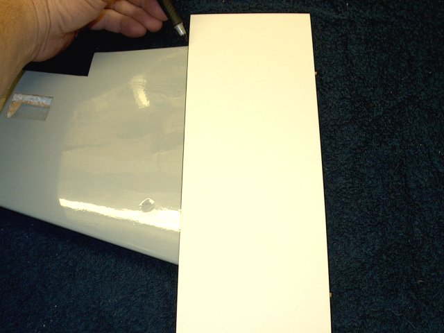
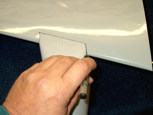
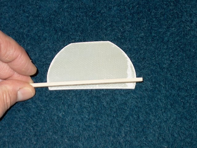
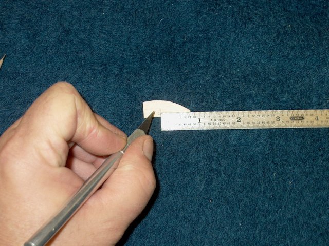
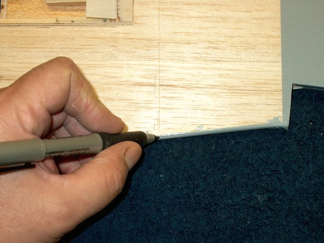
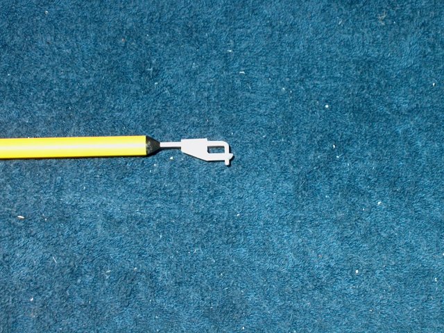
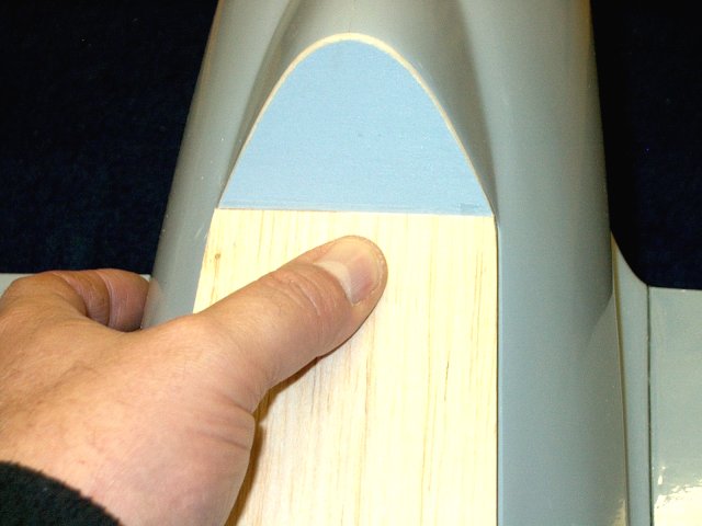
Construction begins by finding the
location of each wing Nacelle. A piece of cardboard is
included in the kit and is 110mm wide, which is a bit too
wide. Hold the cardboard flush with the end of each wing and
draw a reference line | |
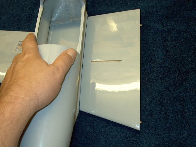
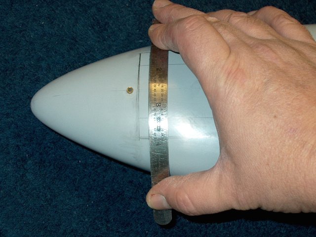
Install a nacelle on each wing up to the
110mm line. Make sure you use the correct nacelle as there is
one for each side | |
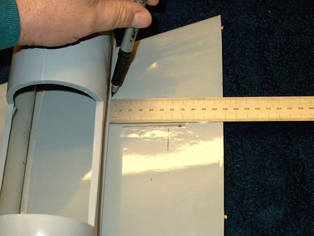
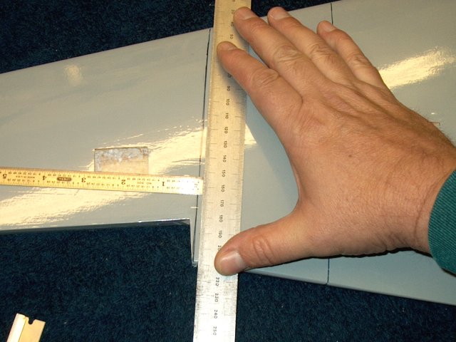
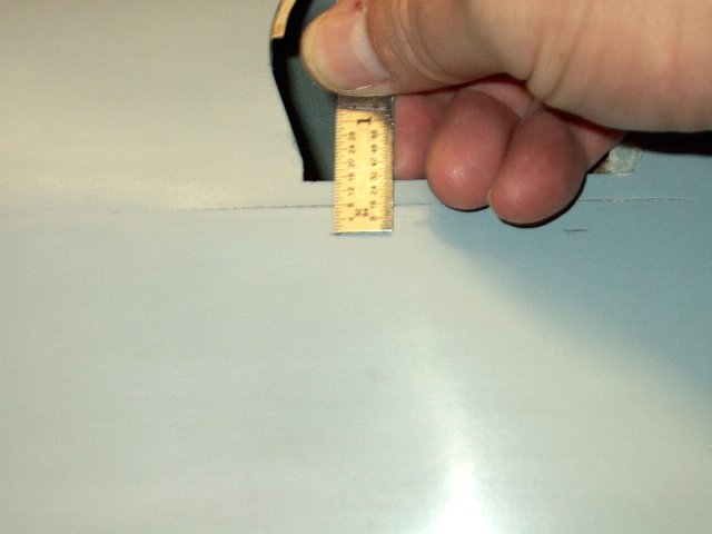
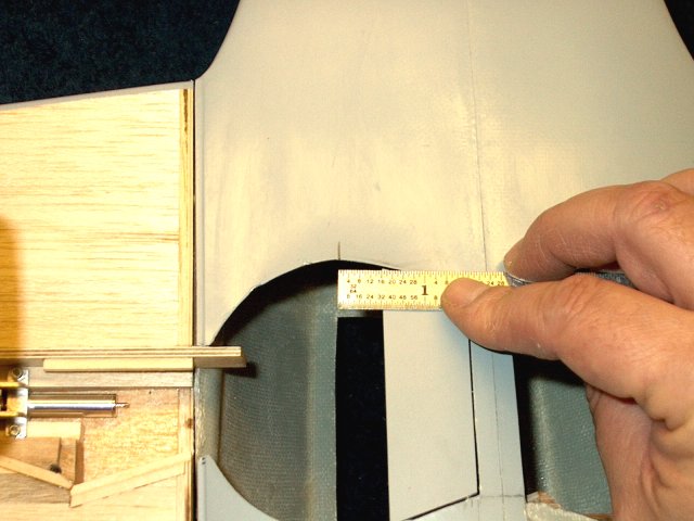
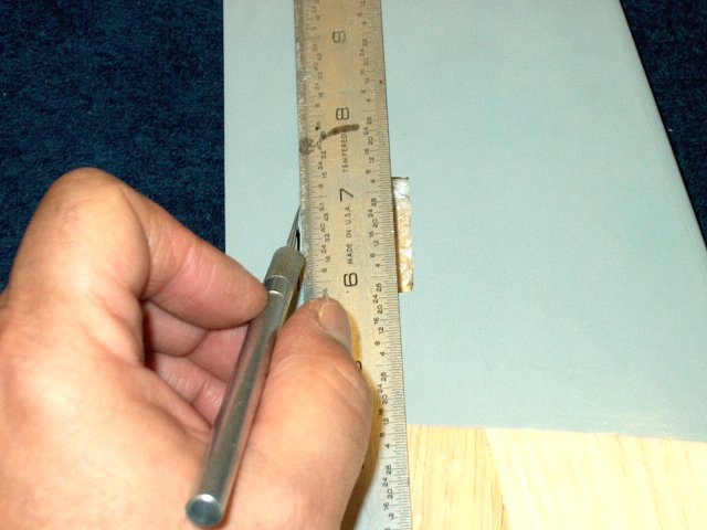
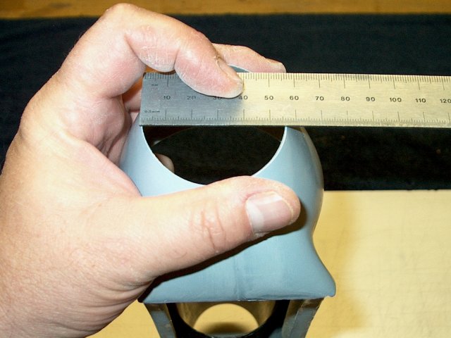
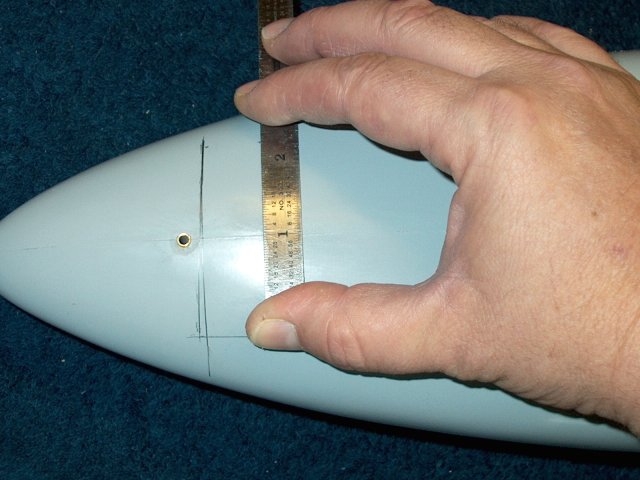
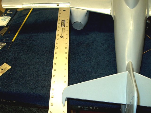
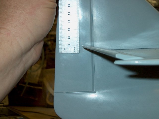
Measure the side of the nacelles at 108mm
from the end of each wing root | |
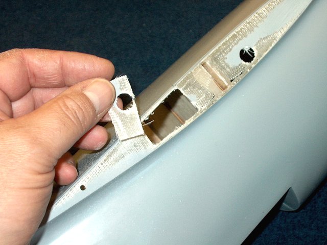
The 108mm measurement moves the nacelle
closer to the fuselage as the original 110mm caused aileron
binding agianst the rear of the nacelle as shown
| |
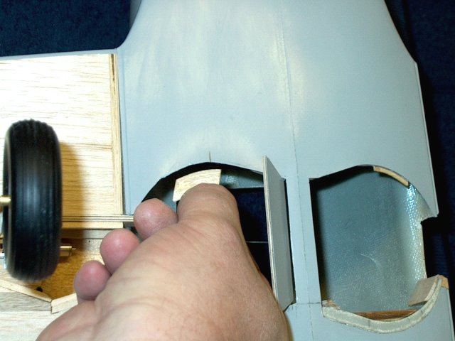
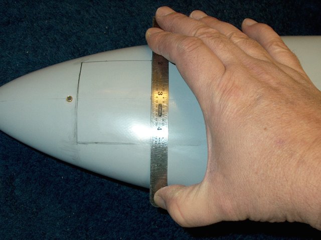
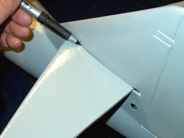
Draw a new outside line, which should be
2mm closer to the wing root. Make sure the rear of the nacelle
clears the Aileron area | |
Draw on the top of the wing the location
of each nacelle | |
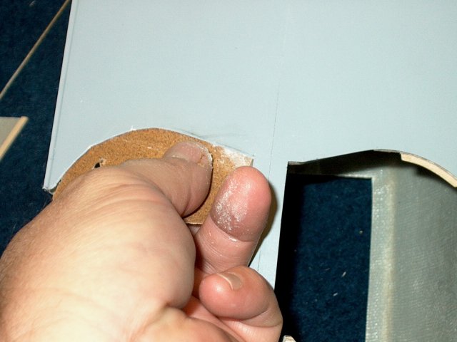
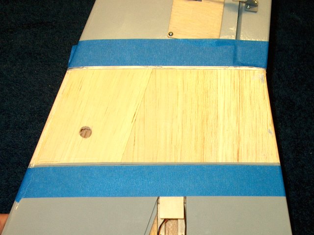
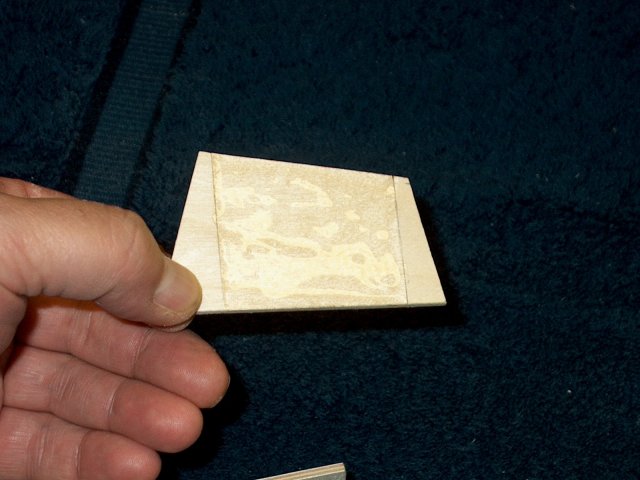
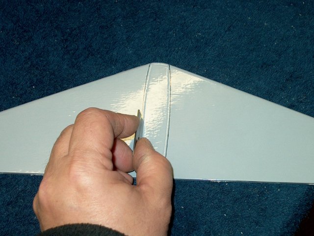
Measure 1/8" inside the outer line on the
bottom of the wing and cut to remove the covering
material | |
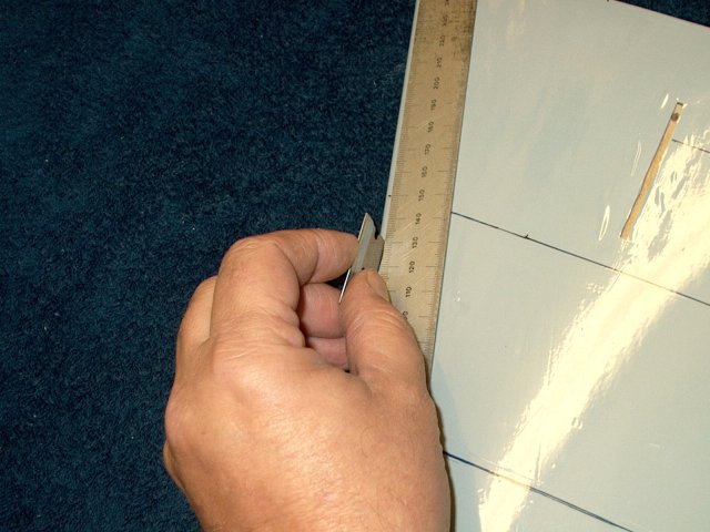
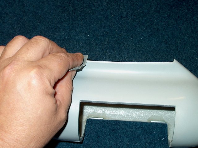
Cut along the leading and trailing edge,
making sure you leave a good 1/8" or more for
re-covering | |
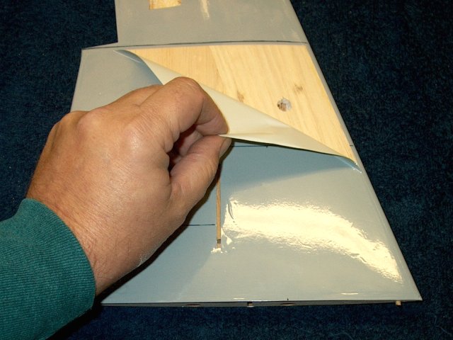
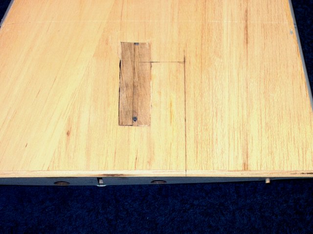
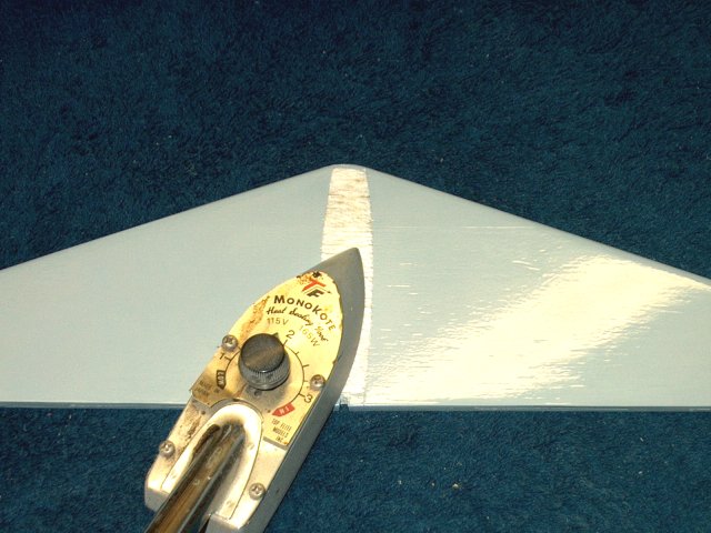
Remove the bottom covering as shown
| |
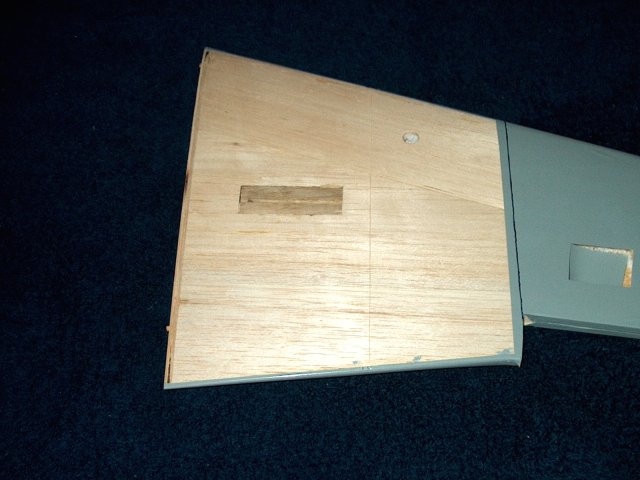
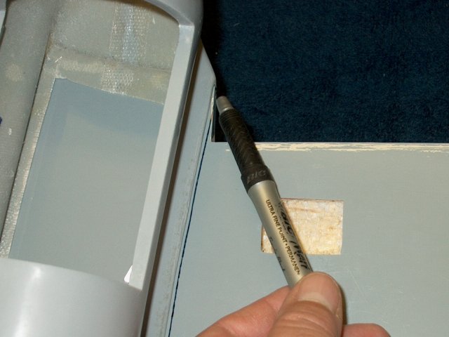
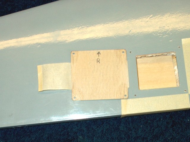
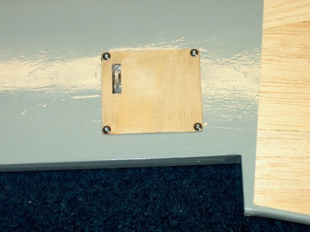
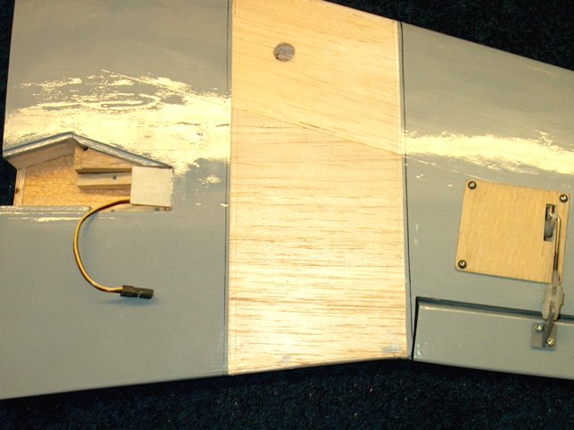
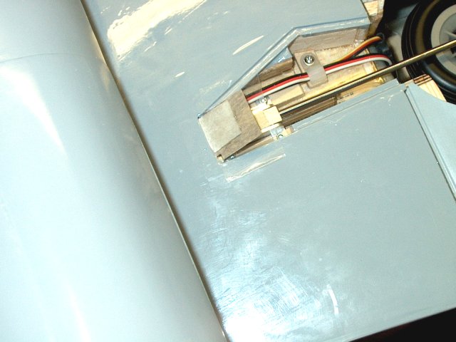
The covering reveals the fixed gear
mounting block, which is used as reference for retract
installation | |
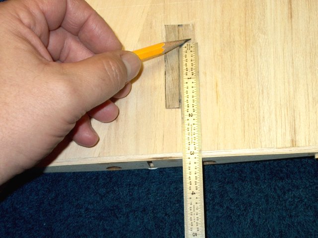
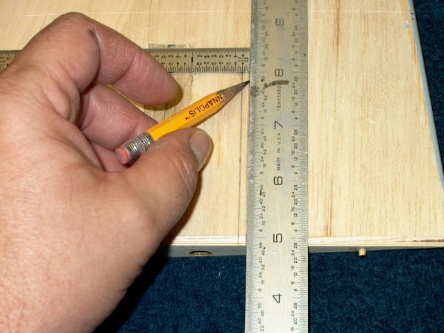
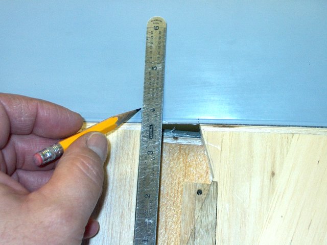
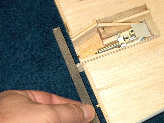
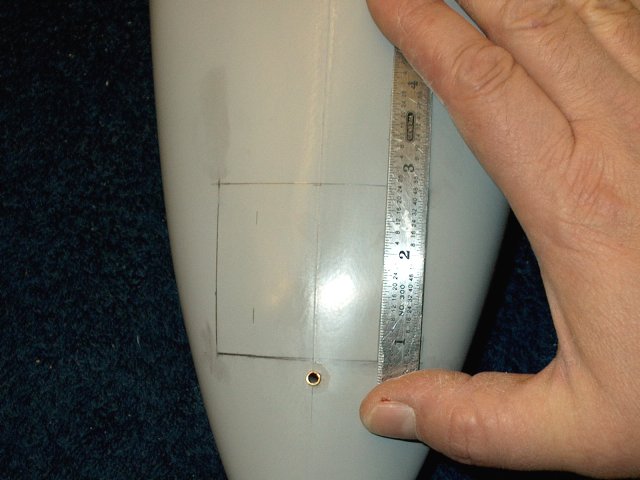
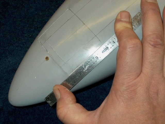
Measure 3 1/4" from the root of the wing
to the rear side of the hardwood block and make a mark
| |
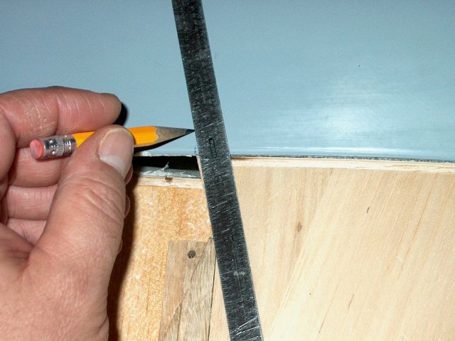
Measure 7/8" from the rear of the block
and mark this location | |
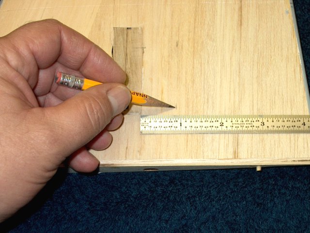
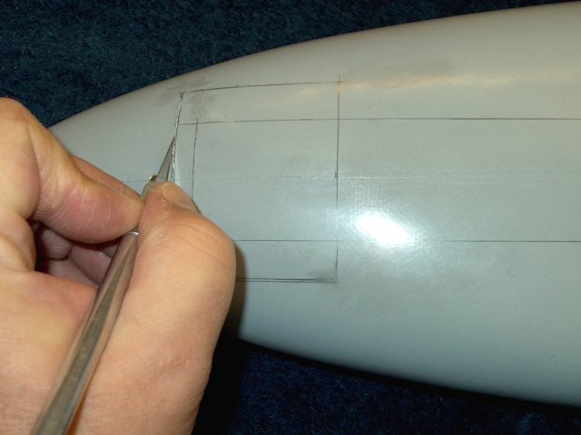
Make a second mark at 7/8" as shown
| |
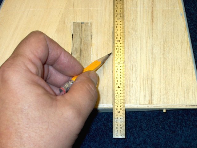
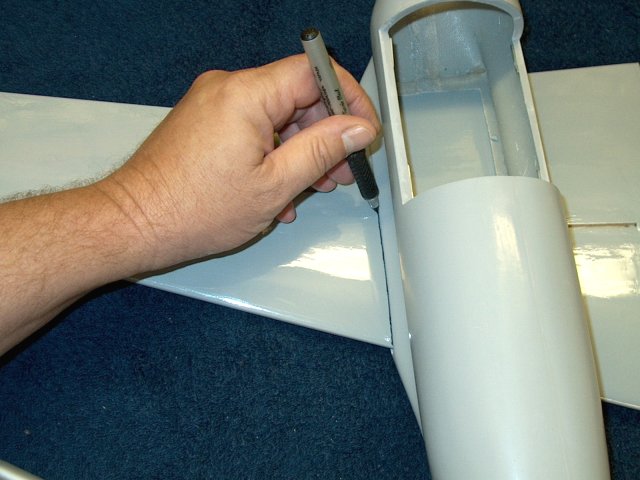
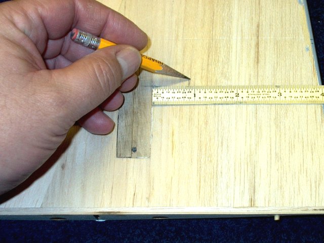
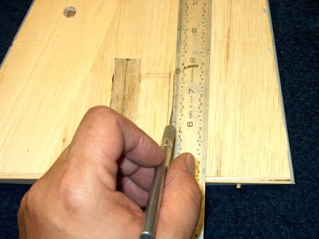
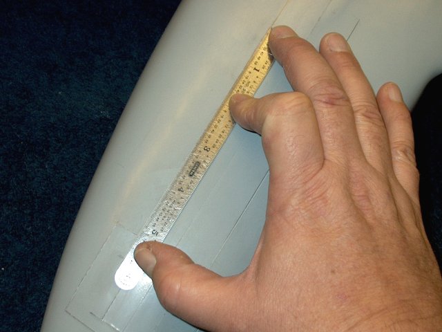
Draw a line through both the 7/8" marks to
the root of the wing | |
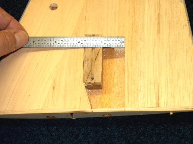
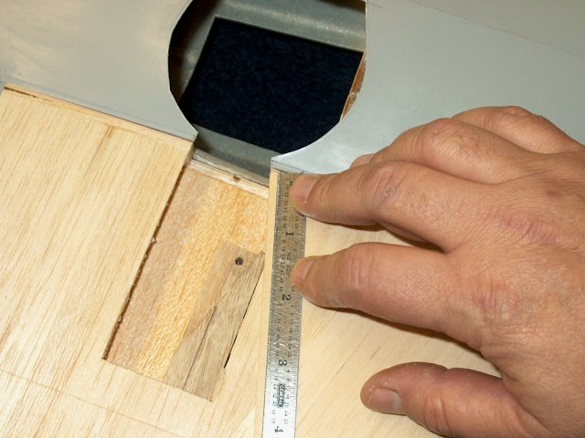
Draw the horizontal top line at the 3 1/4"
mark across as shown | |
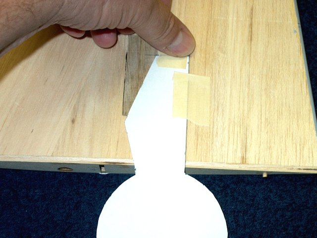
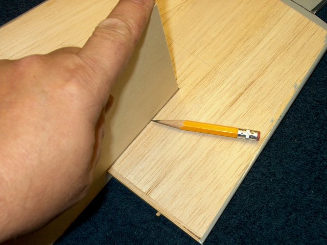
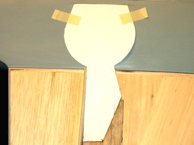
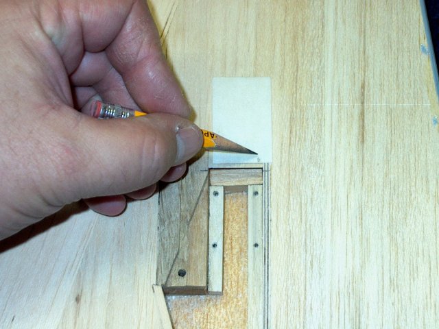
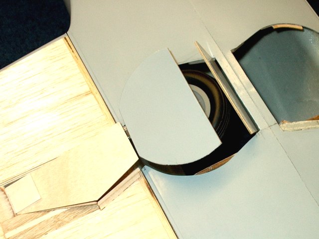
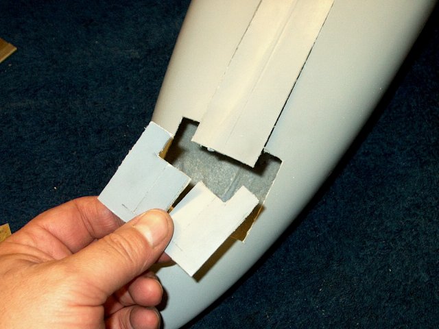
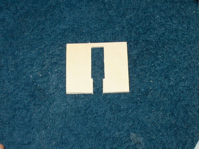
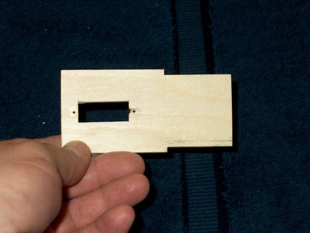
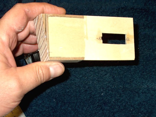
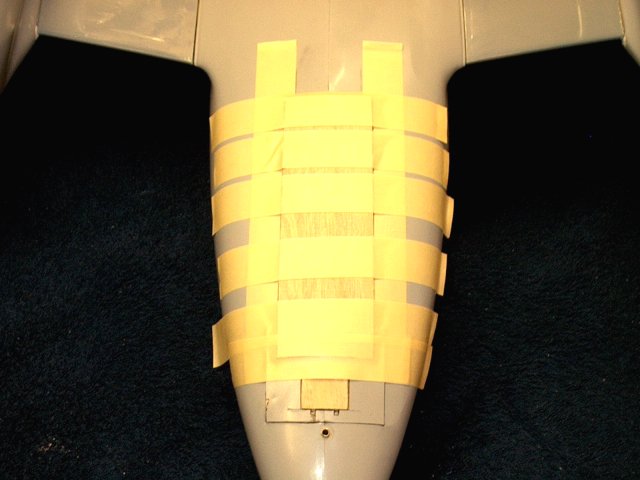
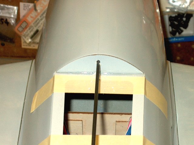
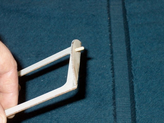
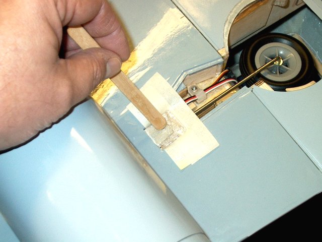
Cut the Main Door Cutout pattern from the
templates and place the back of the door along the vertical
line you drew and the top should be lined up with the 3 1/4"
horizontal line | |
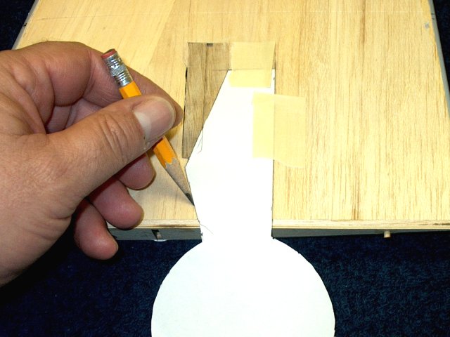
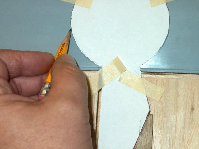
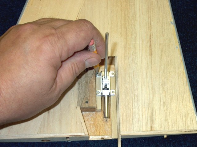
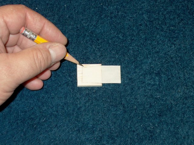
Transfer the front pattern of the door to
the wing as shown | |
Mark and draw a second line at 1/8" past
the first line to allow for the thickness of the Secondary
Spar | |
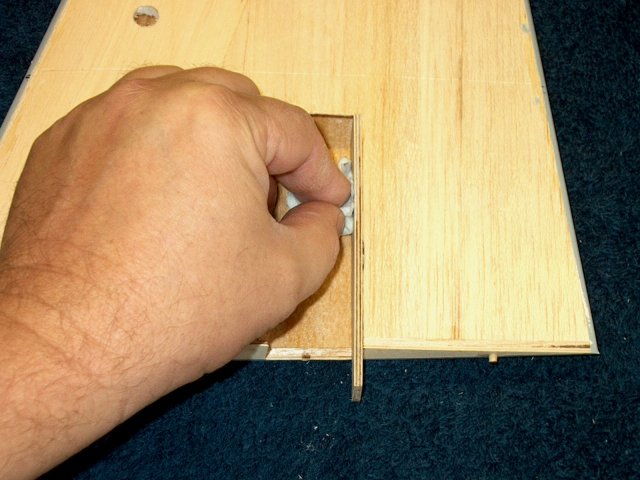
Cut the balsa from the area that was just
marked | |
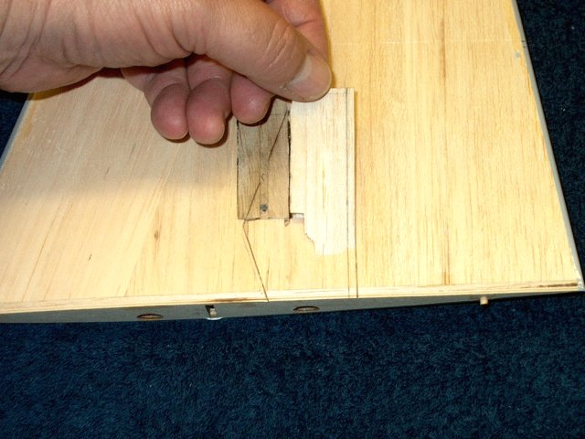
Remove the balsa sheeting and foam from
the area | |
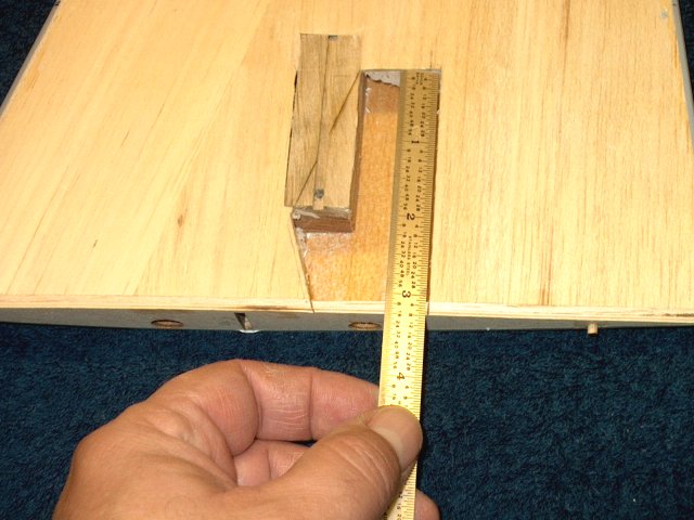
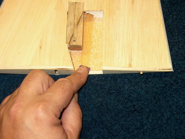
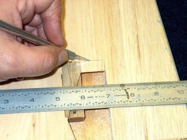
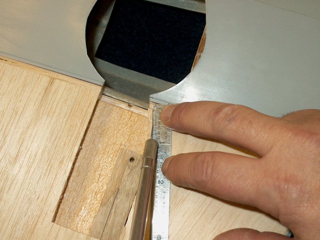
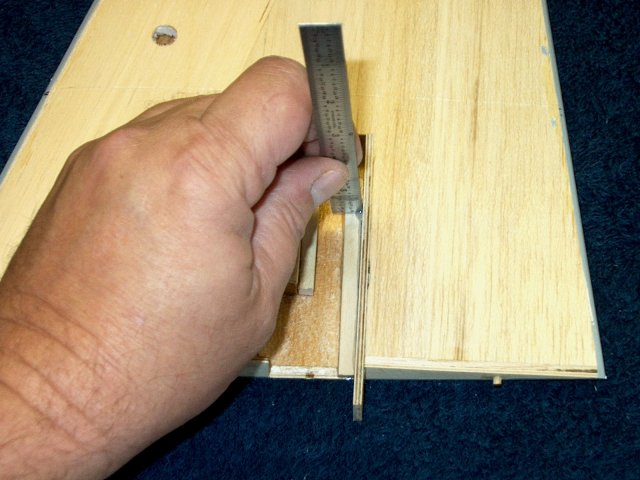
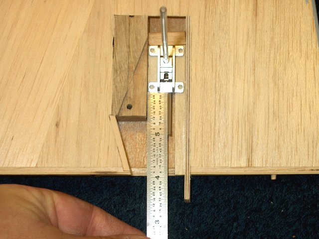
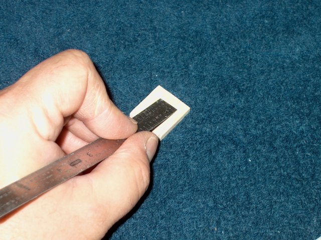
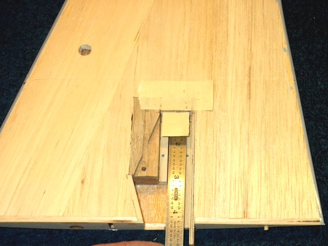
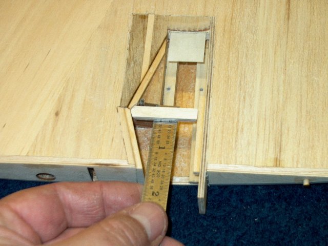
Check your measurement and make sure it
shows 3 1/4" | |
The Trailing edge of the block to the rear
should measure 1" as shown | |
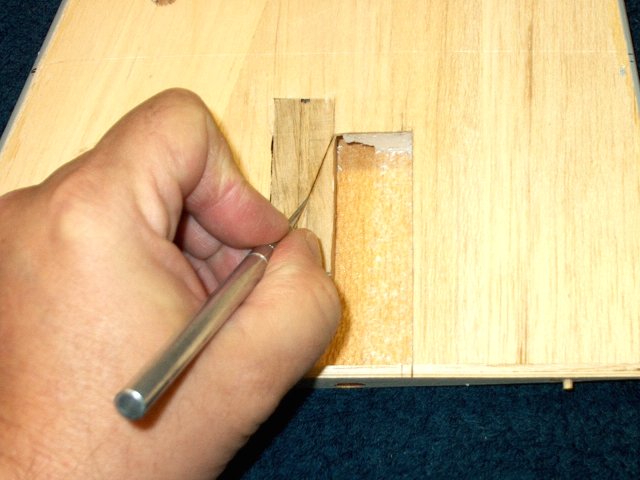
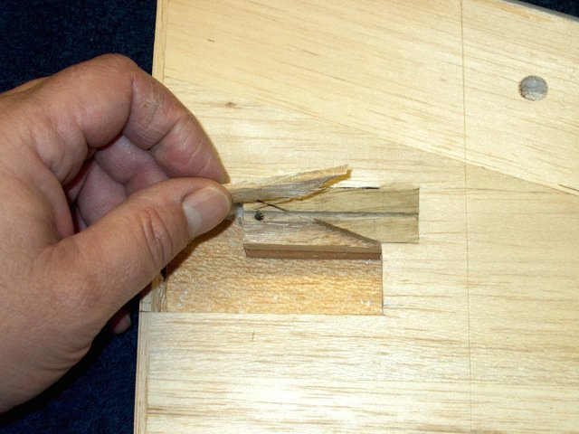
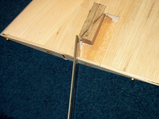
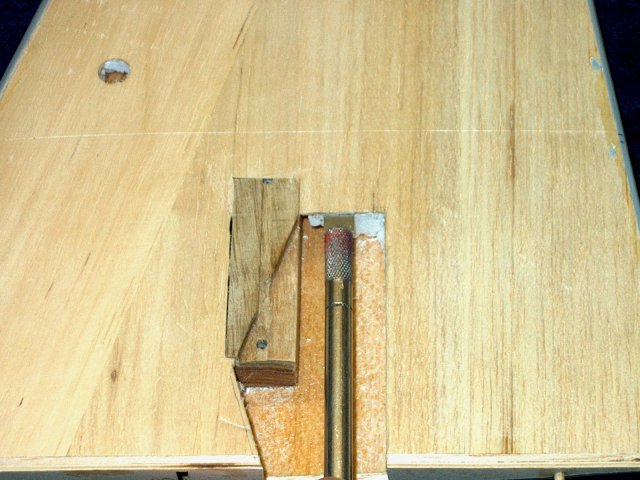
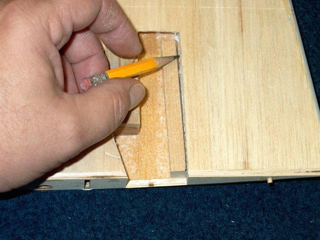
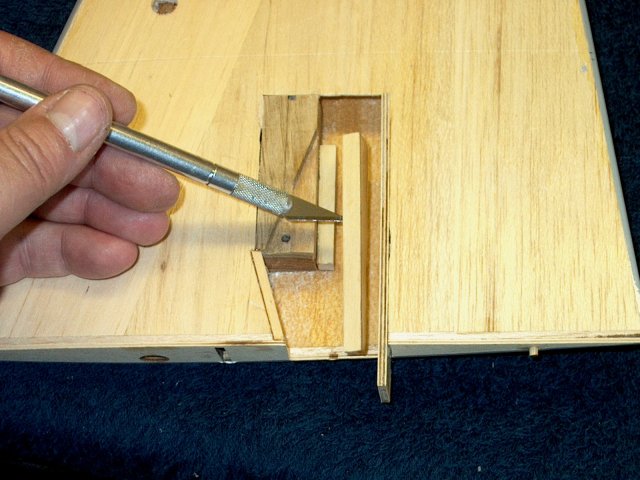
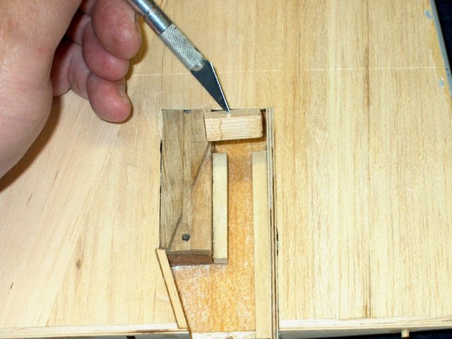
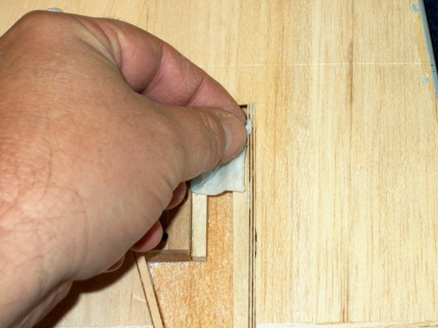
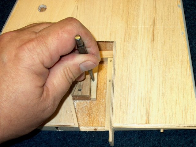
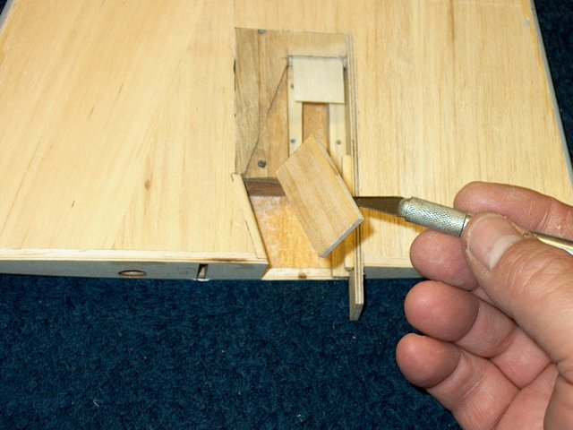
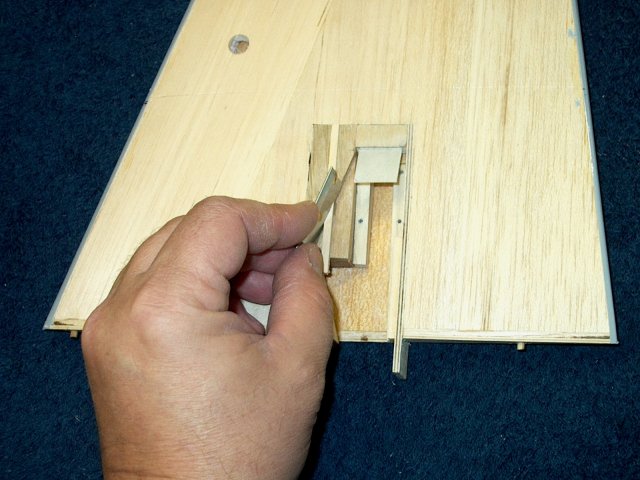
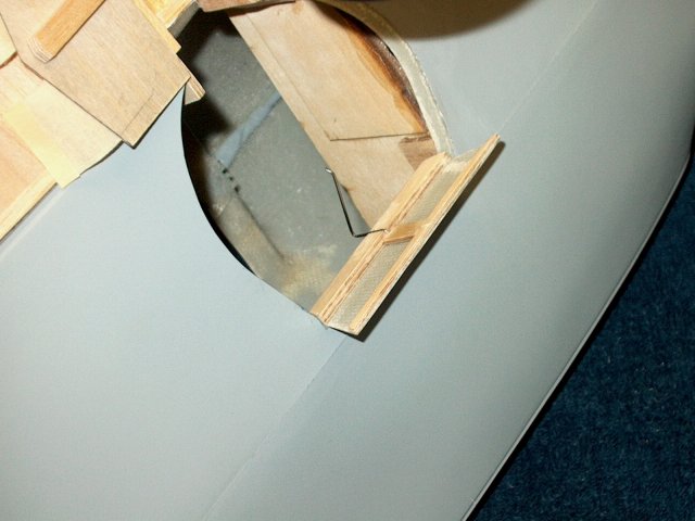
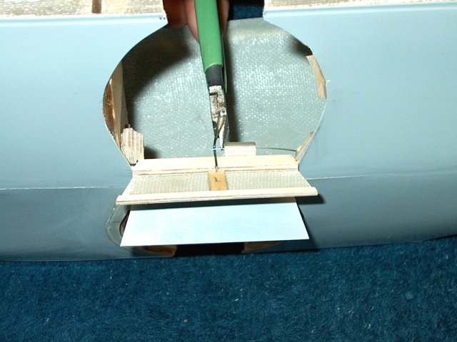
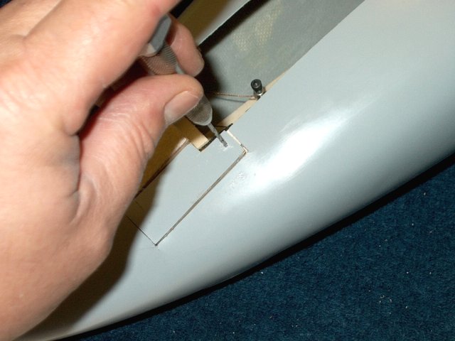
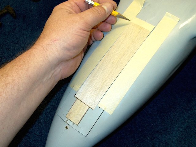
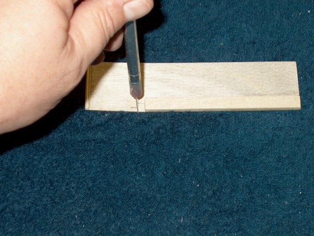
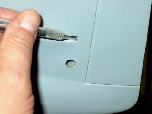
Use an exacto knife to cut into the
hardwood block along the door pattern line
| |
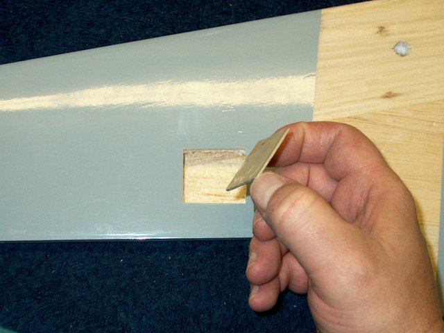
A chisel cutter can be used to cut loose
some of the wood | |
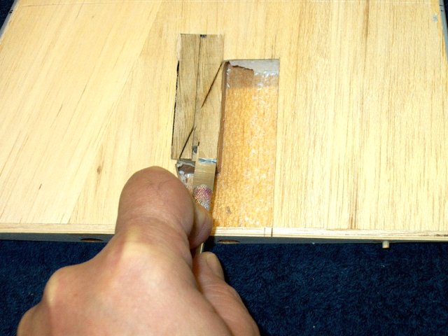
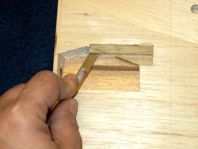
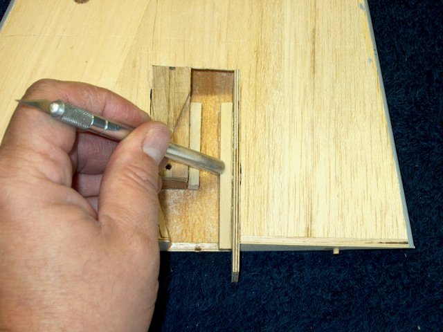
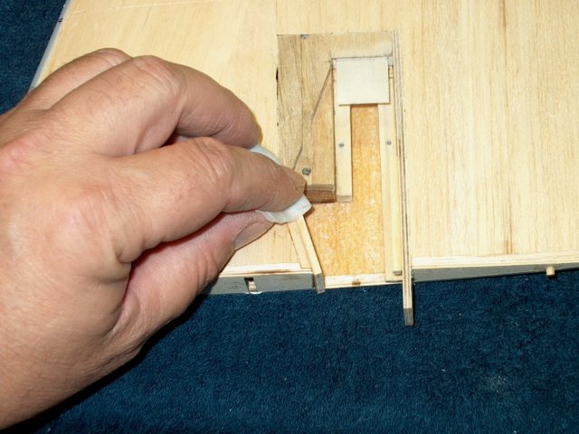
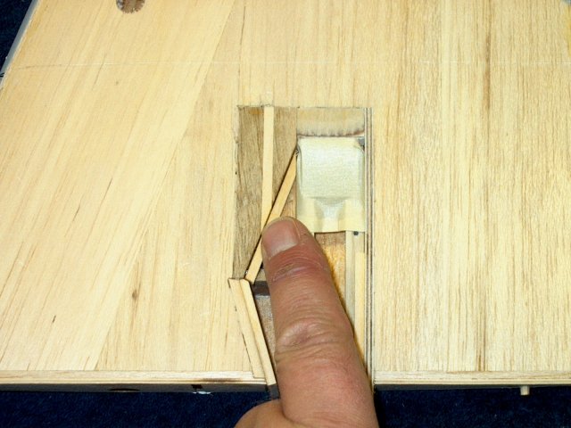
An Exacto knife can be used from the side
of the block to cut the rest of the length
| |
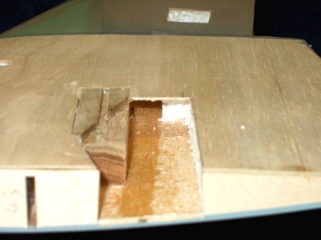
Once cut, remove the excess wood
| |
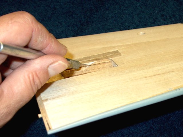
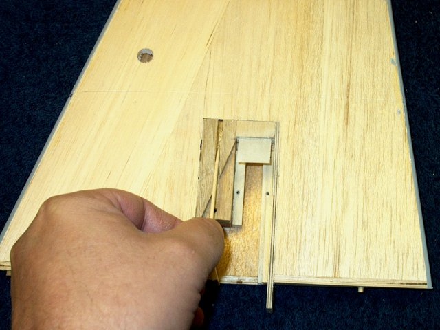
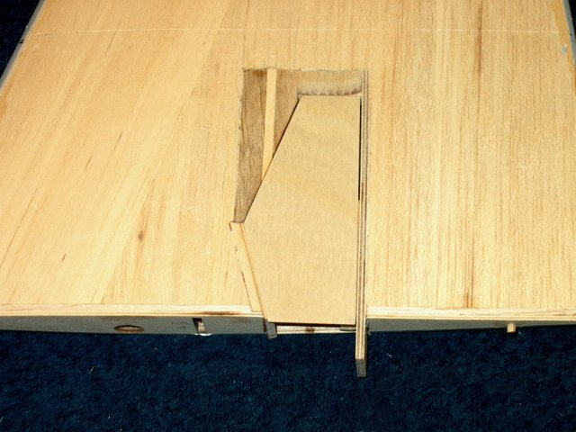
Cut away the remaining block to the door
line using a chisel knife | |
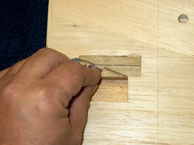
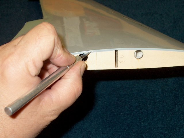
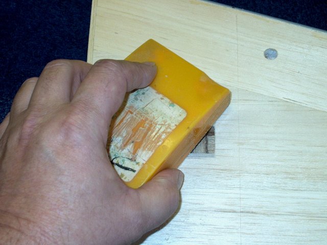
Sand the area smooth to remove splinters
and burrs | |
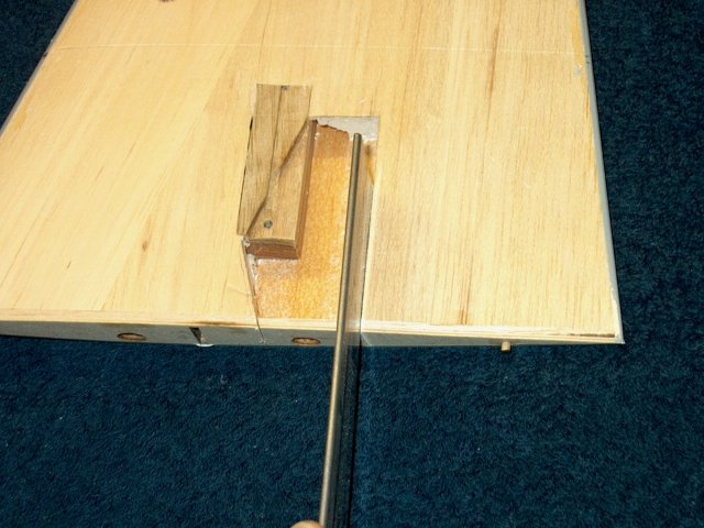
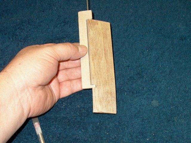
Use a hobby saw and cut the root rear spar
down to the balsa. Try to keep the cut parallel to the main
spar hole in the forward area of the wing root
| |
Cut the front root area in a similar
manner | |
use a knife to cut along the inside of the
wing root and remove the excess | |
Sand the bottom of the area flush to the
wing sheeting | |
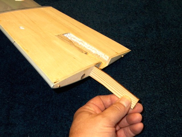
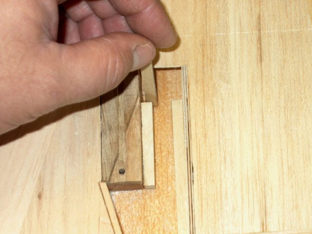
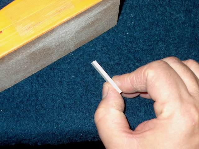
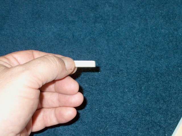
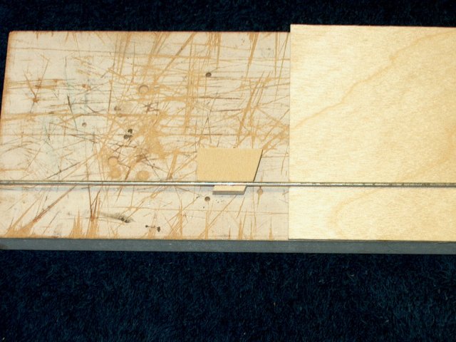
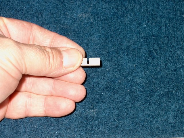
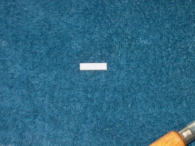
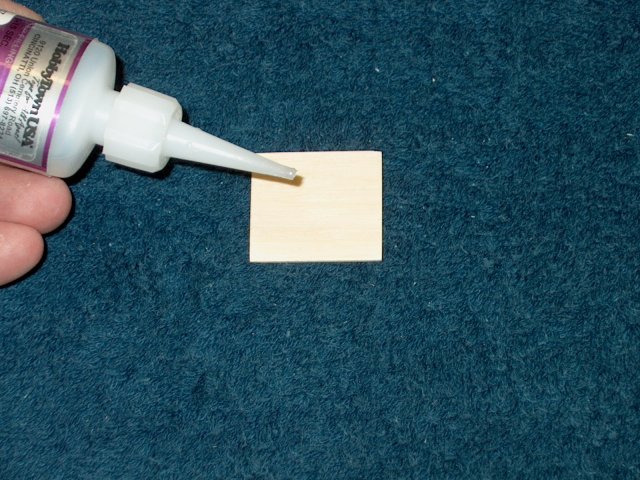
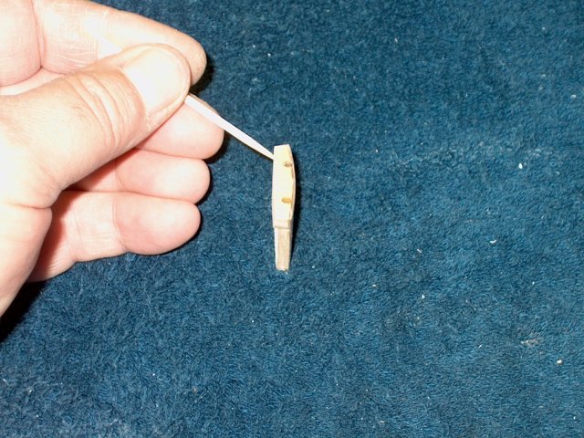
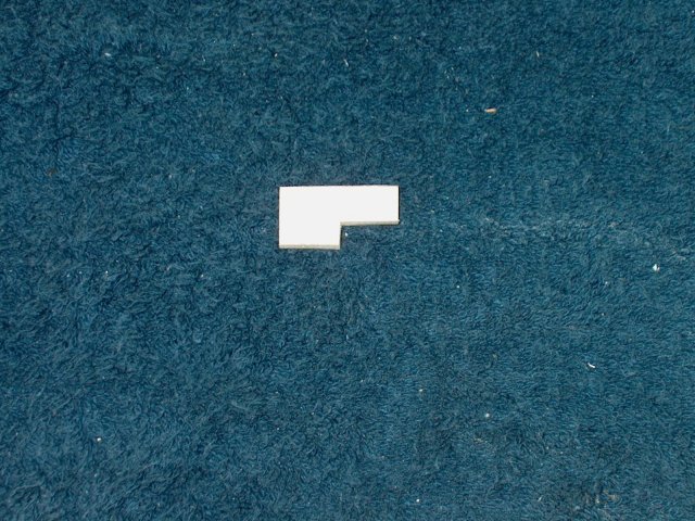
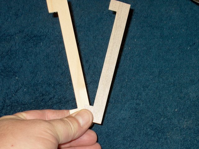
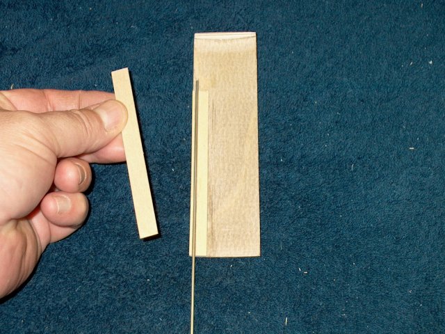
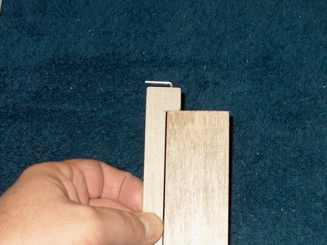
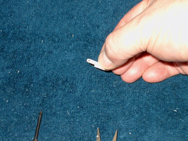
Insert a piece of 1/8" ply sheeting and
draw a line on the sheeting. Cut the Secondary Spar to length
as shown in the templates | |
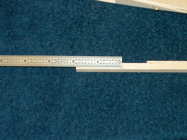
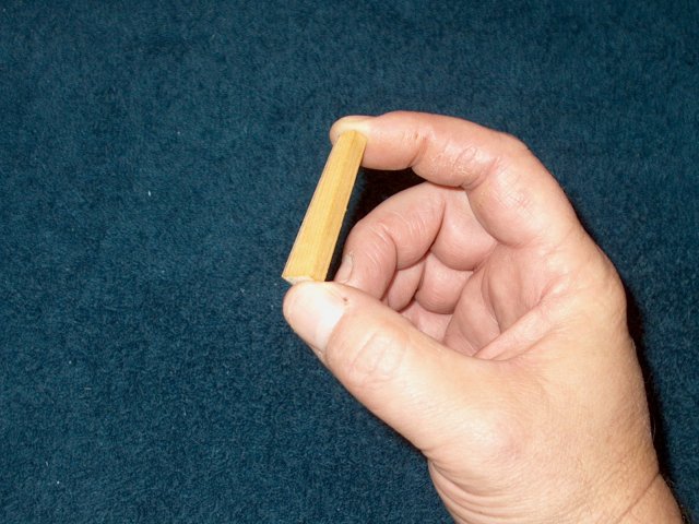
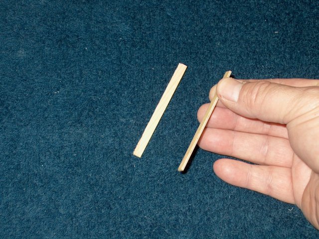
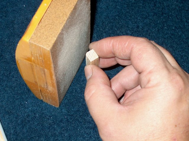
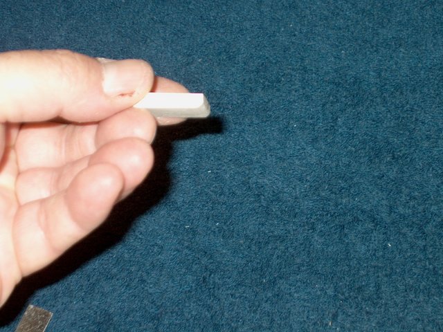
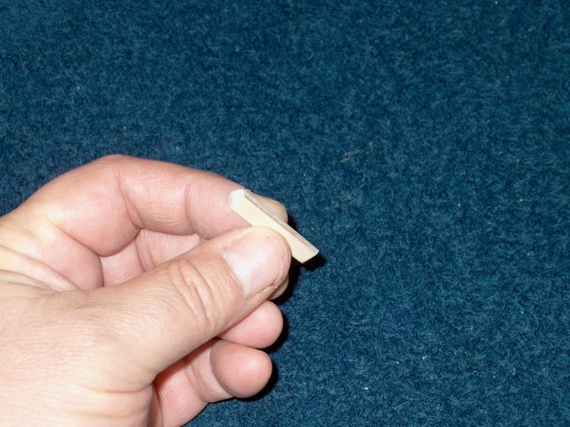
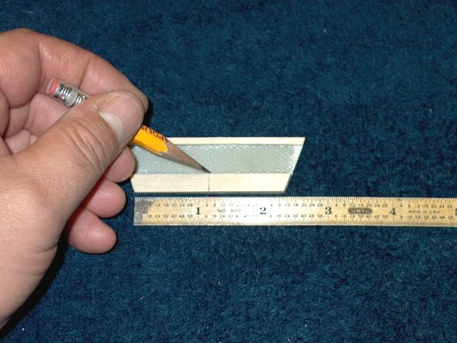
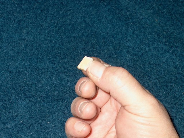
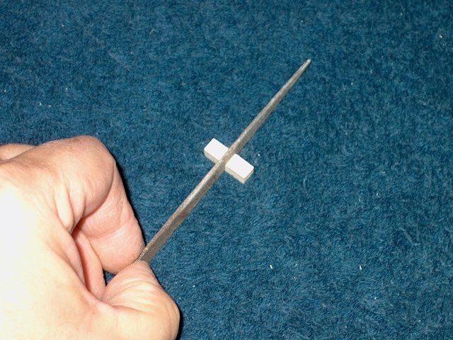
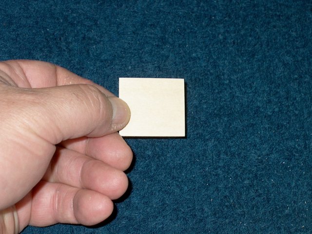
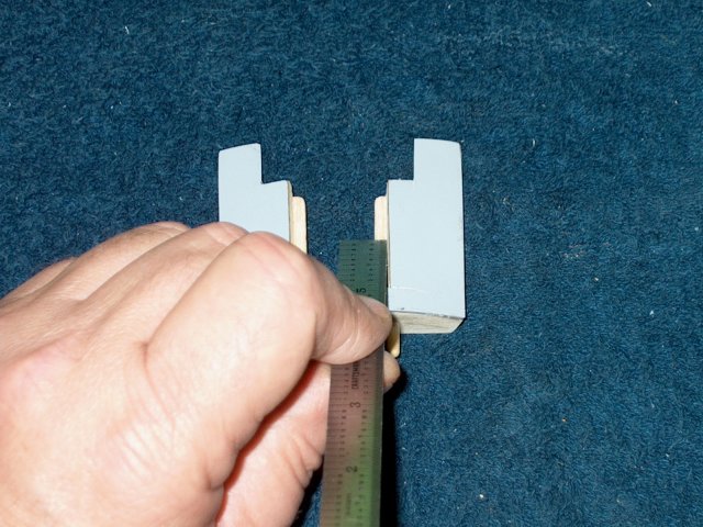
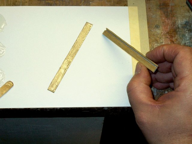
Cut a piece of 1/4" x 3/8" hardwood block
to a length of 1 7/8" ; Note that the wood shown in the pic is
3/8" square and had to be cut to the correct 1/4" x 3/8"
dimensions | |
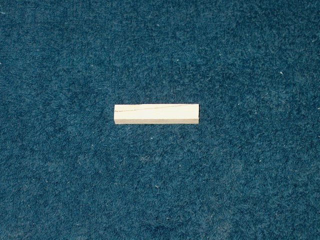
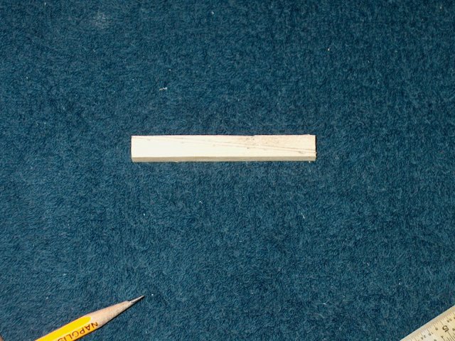
Draw a line along the block as shown to
match the one in the templates | |
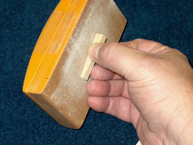
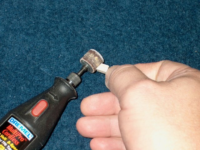
Sand the surface smooth
| |
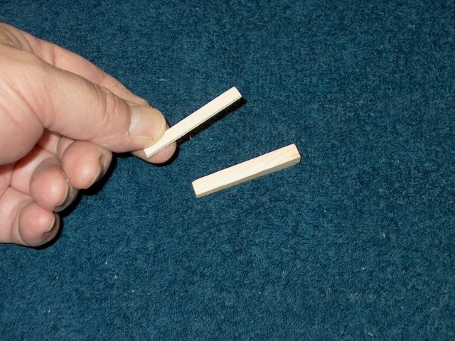
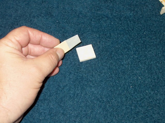
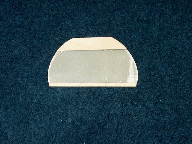
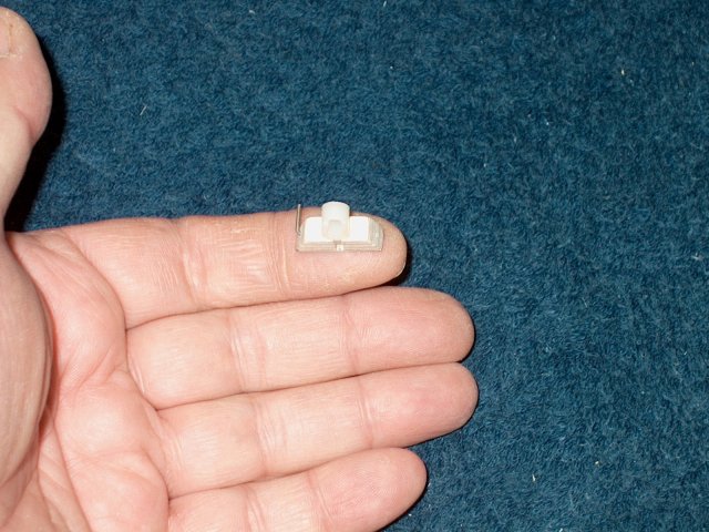
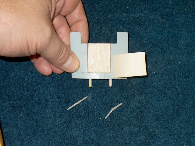
Cap the top of the block with a 1/16"
thick piece of aircraft ply | |
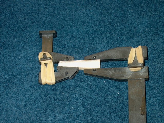
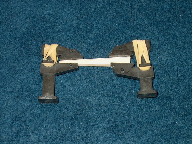
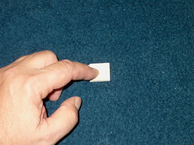
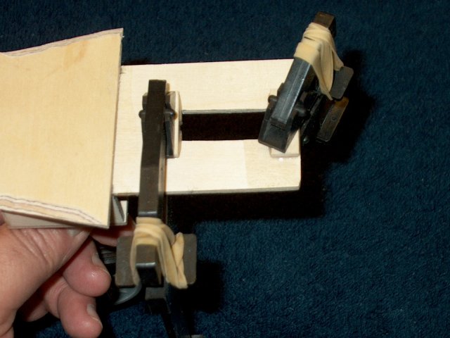
Clamp the assembly until the epoxy
sets | |
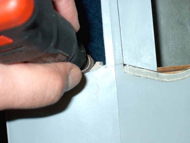
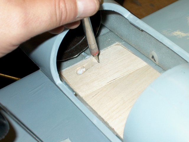
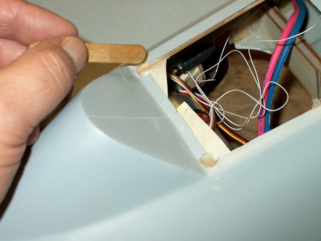
Use a knife to cut away the foam underneat
the top side of the wing as shown | |
Cut back the foam about 1" or more; clean
up the hole for the aileron servo wires
| |
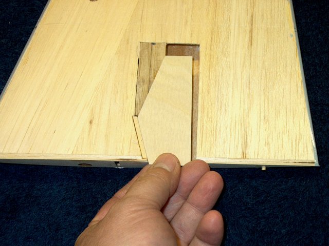
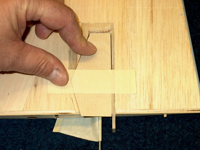
Remove the extra piece of balsa as shown.
Cut it from the fuselage opening to the outside top of the
hardwood block | |
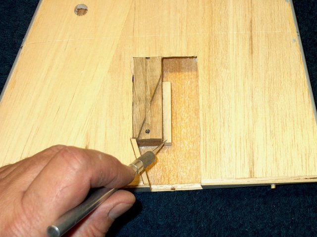
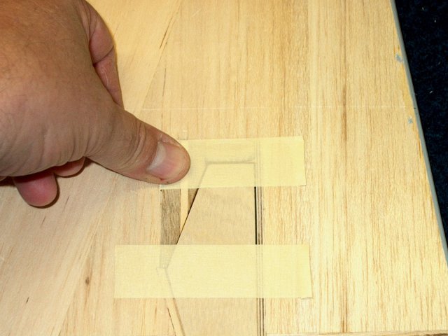
Cut a 3" long piece of 3/8" square
hardwood and use it to mark the foam on the right side as
shown. Remove the foam below the line so the block can sit
recessed in this area under the wing sheeting and even with
the top opening | |
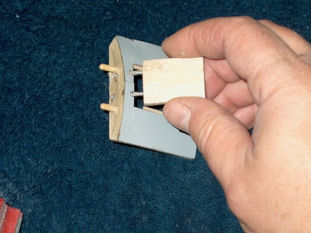
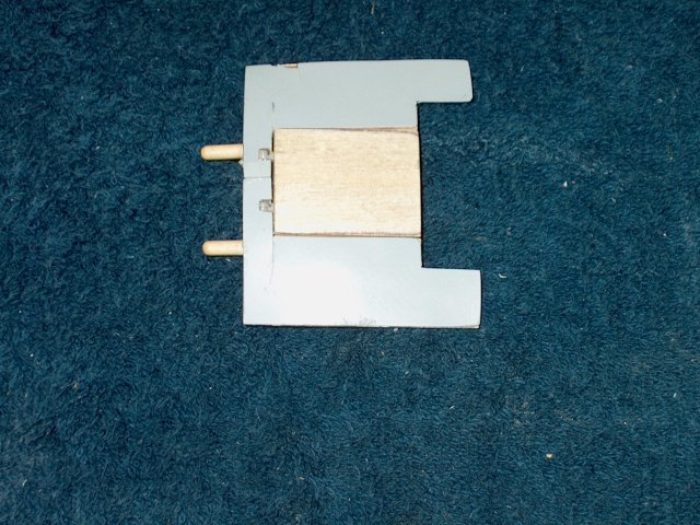
Install the main spar
| |
Install the wing in the fuselage
| |
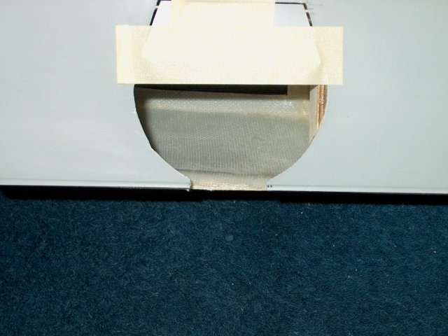
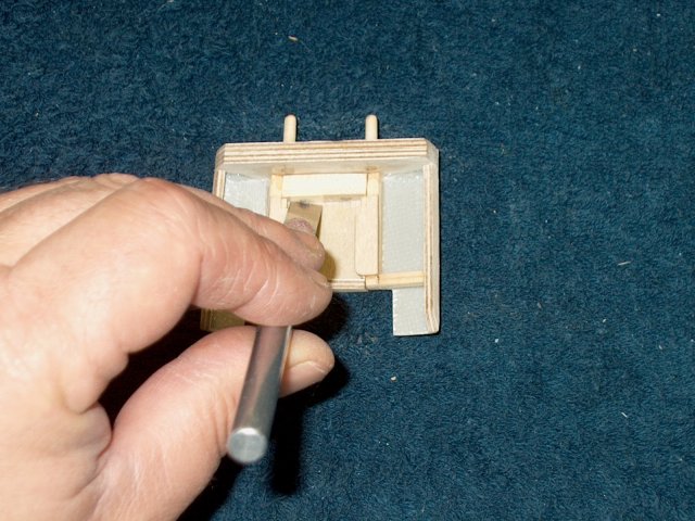
Transfer the outline of the wing's cut out
area to the fuselage | |
Use a sharp knife to remove this area from
the fuselage. Sand the inside edges smooth once
finished | |
Measure 1/4" down from the seam of the
fuselage on the bottom of the jet and draw a line parellel to
the seam | |
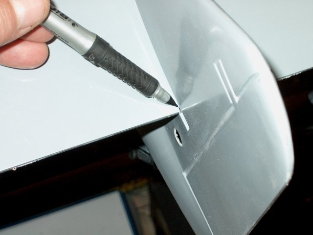
With the wing installed flush, make a line
from the rear of the wing opening to the fuselage
| |
Make a line from the front of the wing
opening to the fuselage, matching the angle
| |
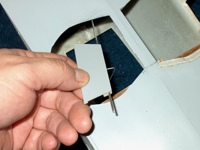
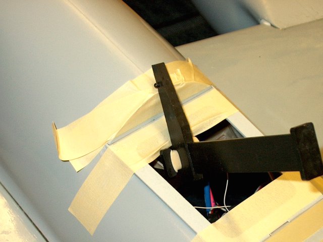
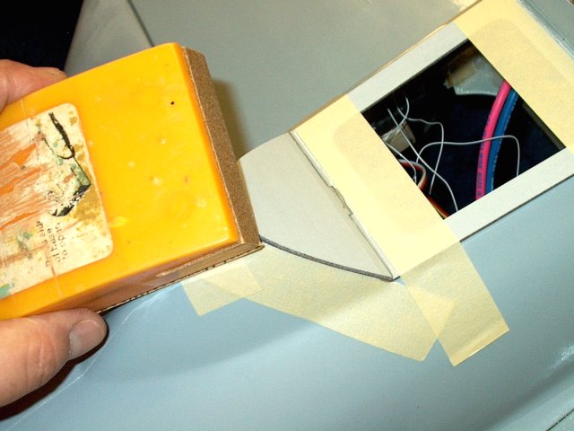
Install the template with the top at the
1/4" from the seam horizontal line and the bottom between the
two marks you just made. The rest of the pattern should align
with the wing door area as shown | |
Transfer the pattern to the fuselage
area | |
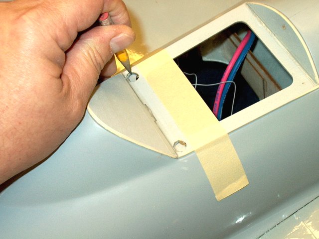
Carefully cut out the pattern in the
fuselage. This will take some time, possibly an hour or more
and may take 30-40 passes with an exacto knife on each side.
It takes a couple blades to cut through the entire area. If
you run into a glue area, try to pop the fuselage free of the
glue rather than cut through the glue, which will be
reinforced later. Also note that one side will expose some of
the main spar support plywood and glue. Take care not to cut
into the ply | |
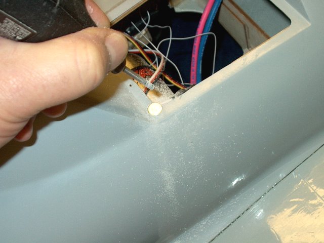
Lightly sand the area that was cut out and
clean it up | |
Measure in 1/8" from the front inside door
run as shown | |
Cut the balsa to the elbow, but leave the
foam core in place | |
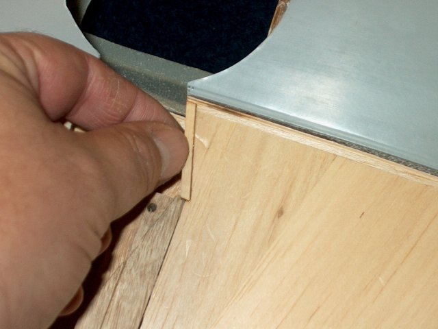
Cap the area with a 1/8" wide by 1/16"
thick piece of basswood strip. Epoxy it in place
| |
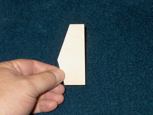
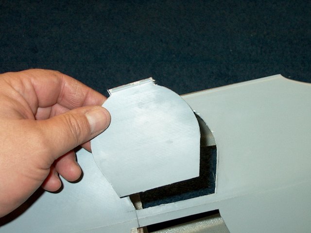
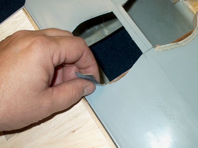
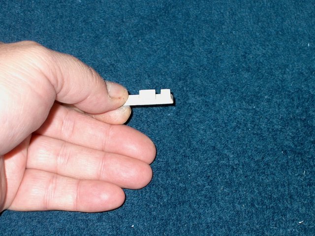
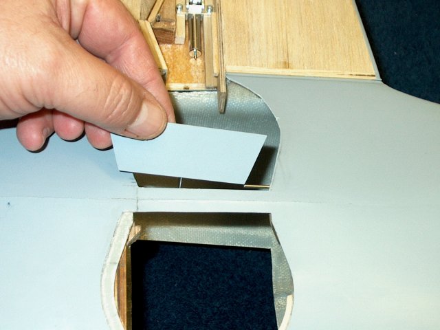
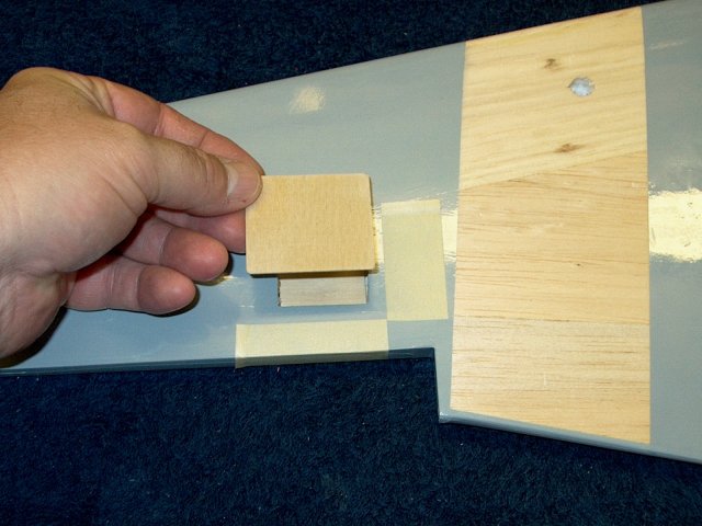
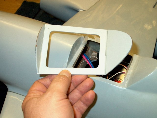
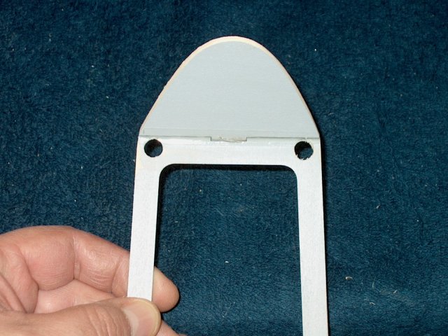
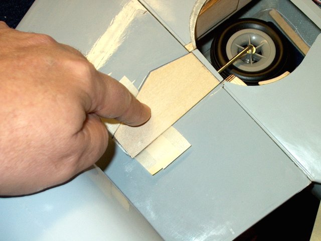
Cut out the wing door from the
pattern | |
Check the fit on the door
| |
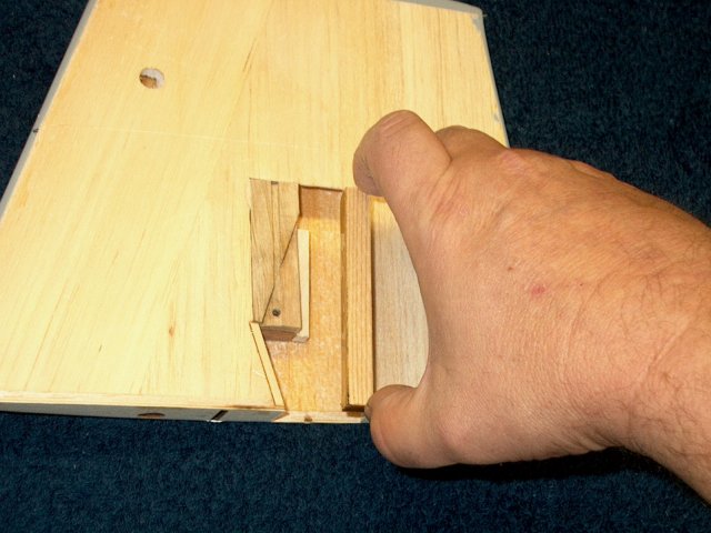
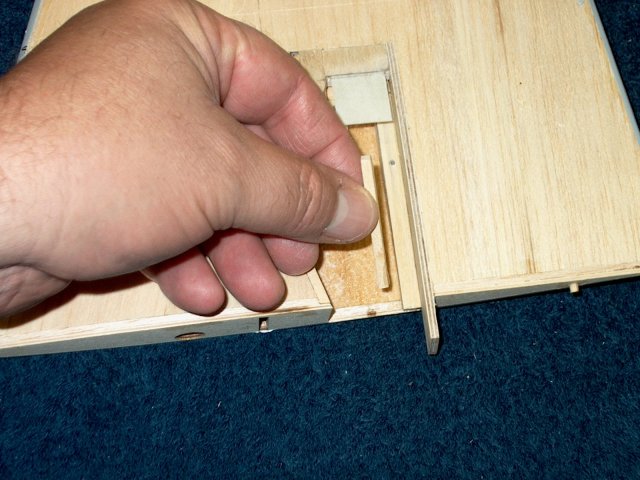
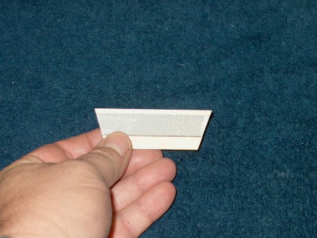
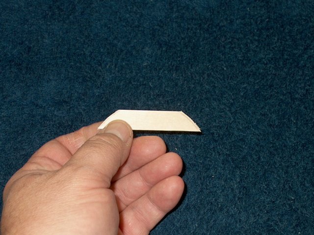
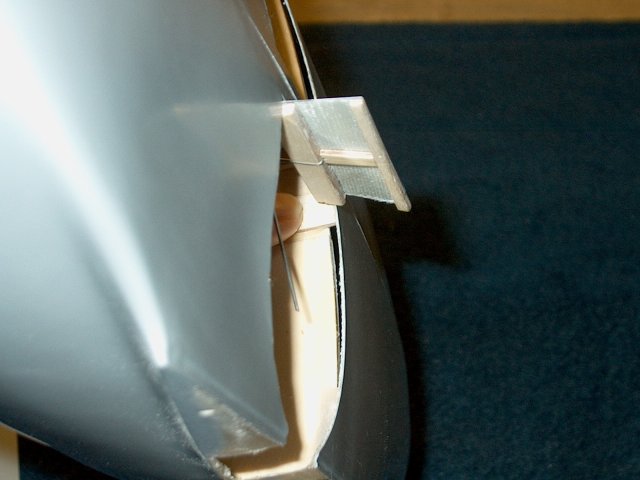
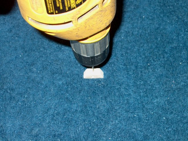
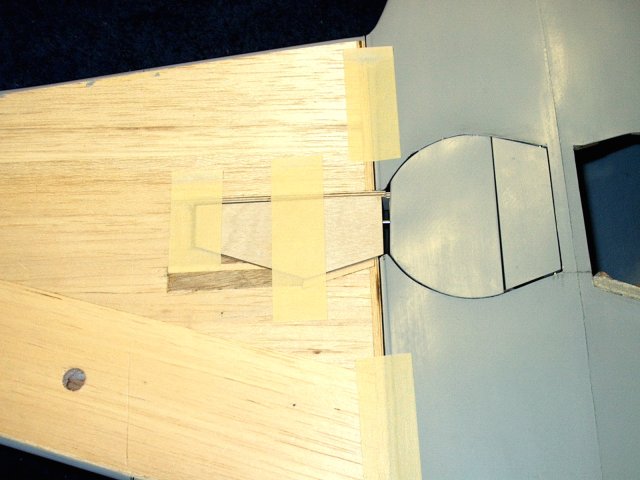
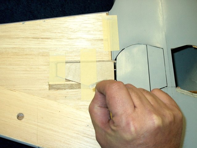
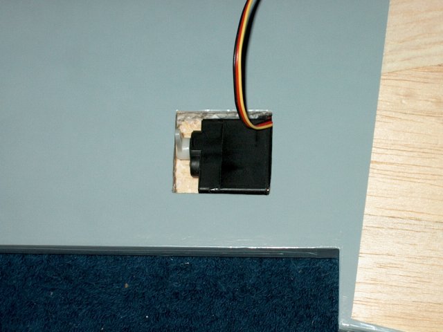
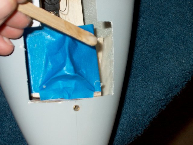
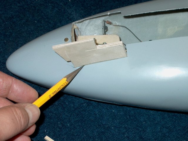
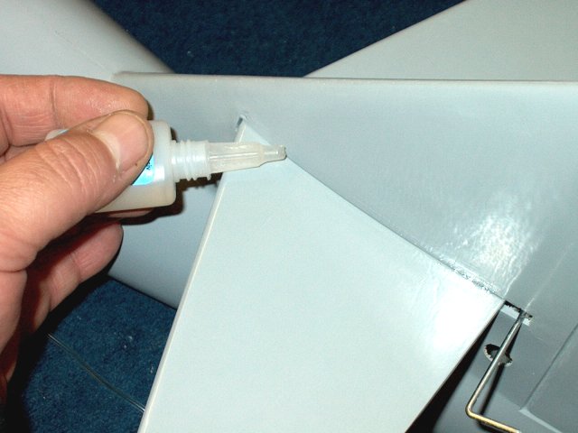
Add Epoxy to the Retract wedge top and
outside | |
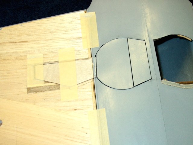
Install the wedge as shown, with the
inside of the wedge aligned with the bottom end of the harwood
block | |
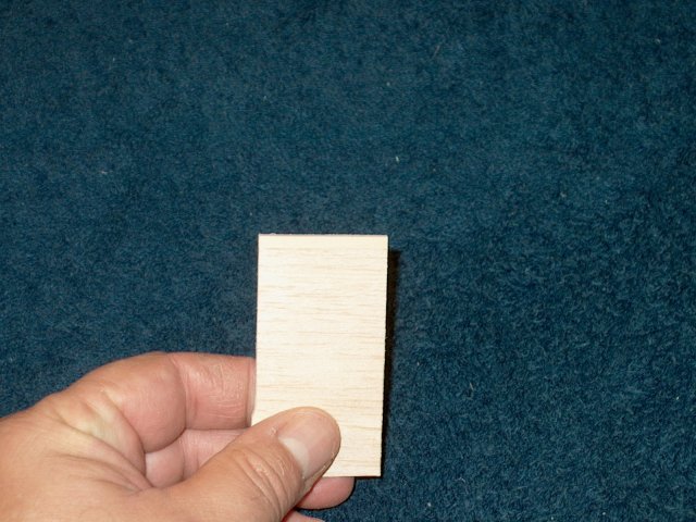
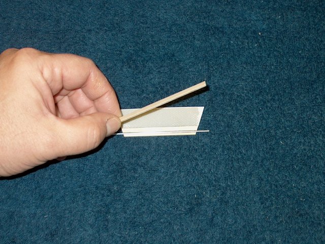
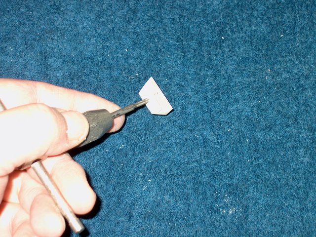
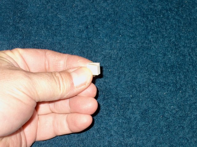
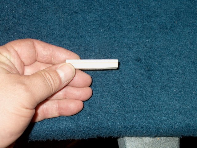
Cut a second wedge, 3" long from 1/4" x
3/8" hardwood using the supplied pattern
| |
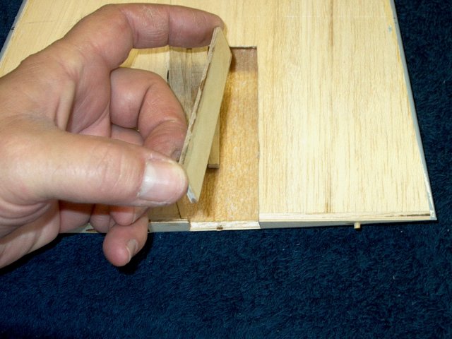
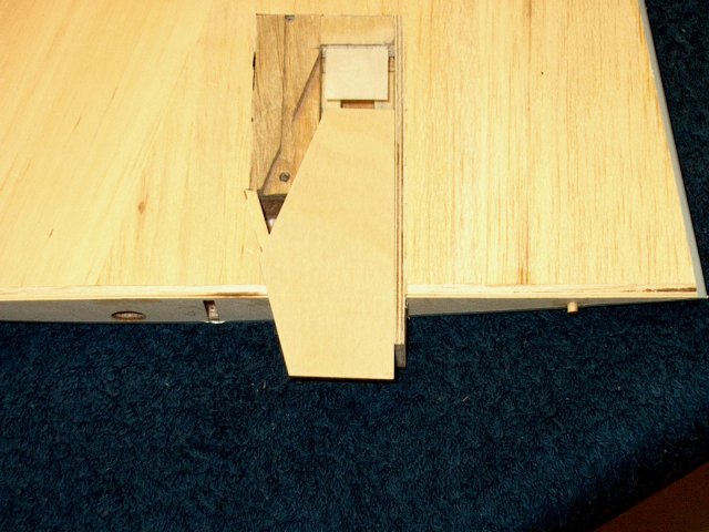
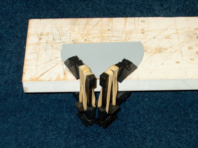
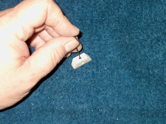
Cap the wedge on the top with a 1/16"
thick strip of aircraft ply | |
Clamp the assembly and allow the epoxy to
set | |
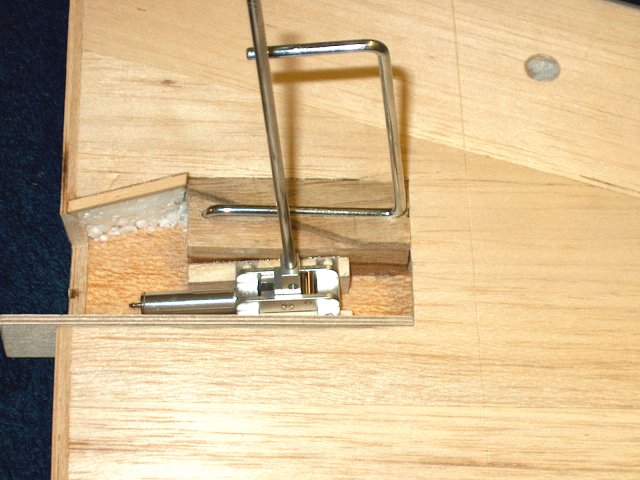
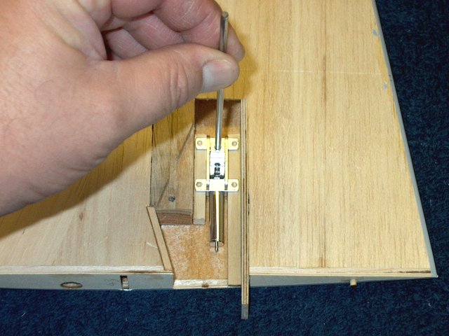
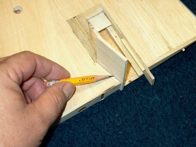
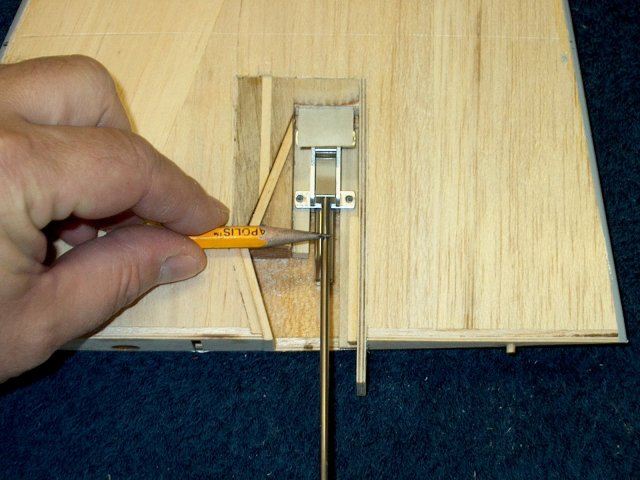
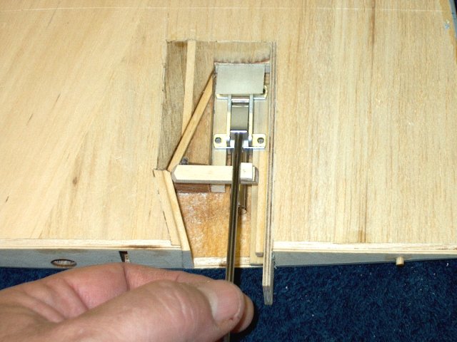
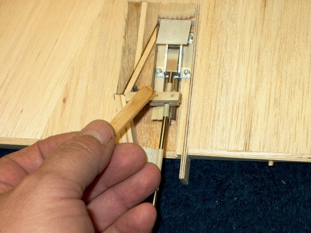
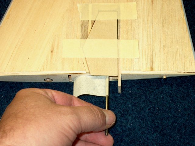
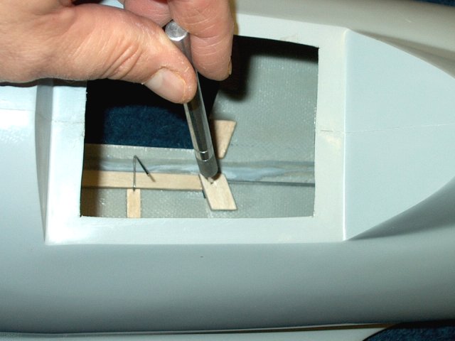
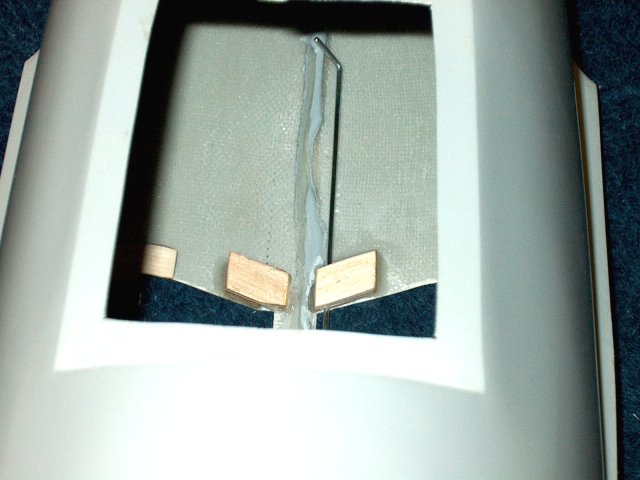
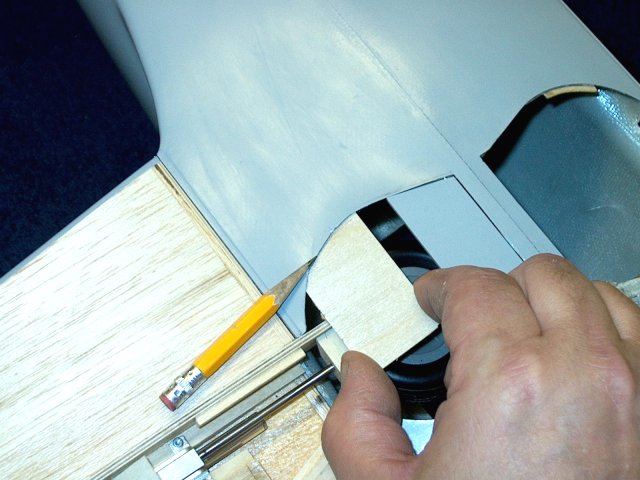
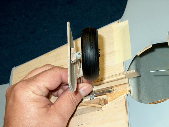
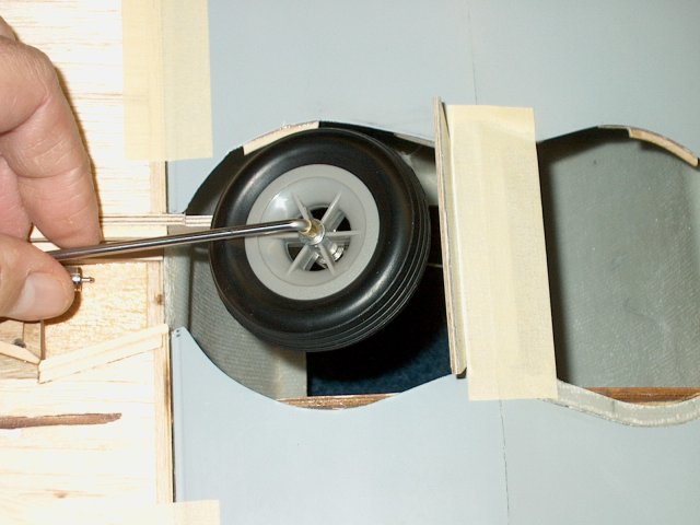
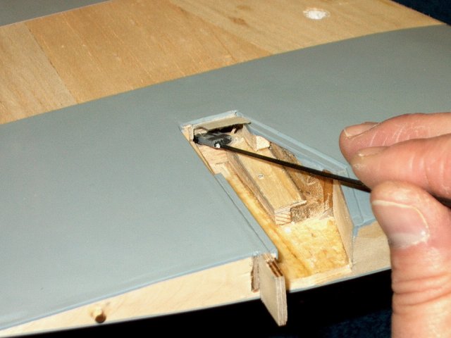
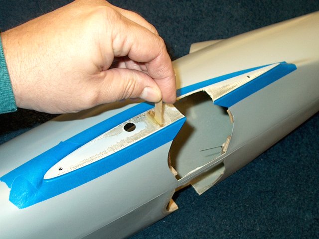
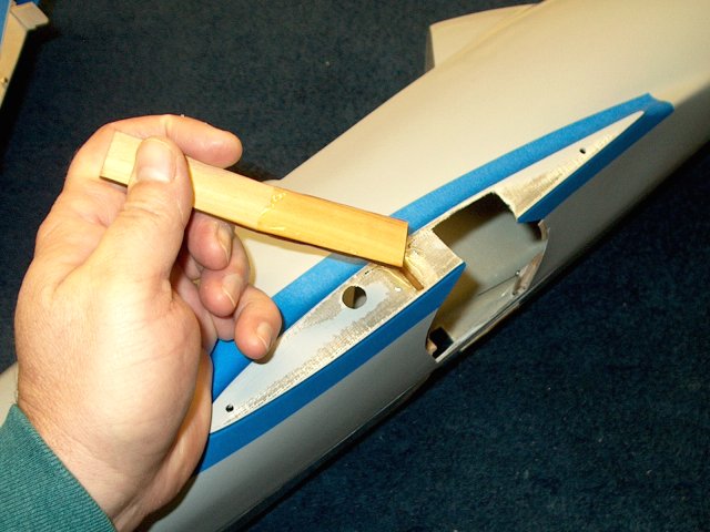
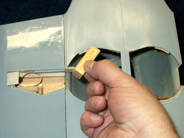
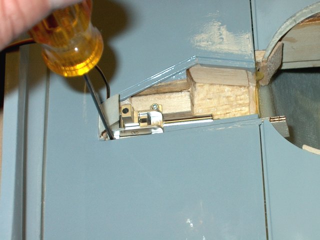
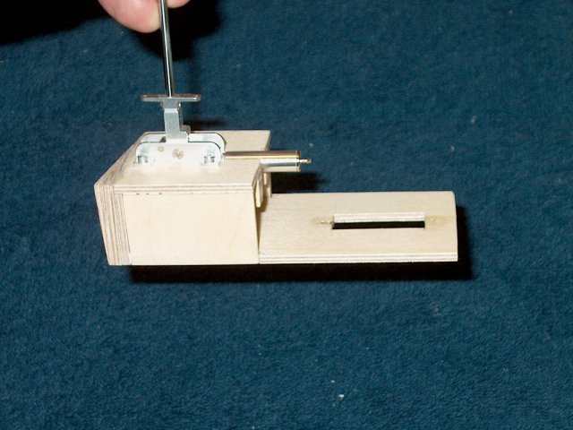
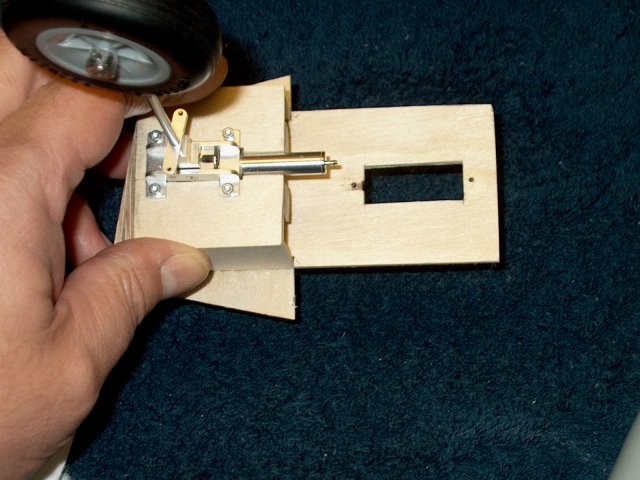
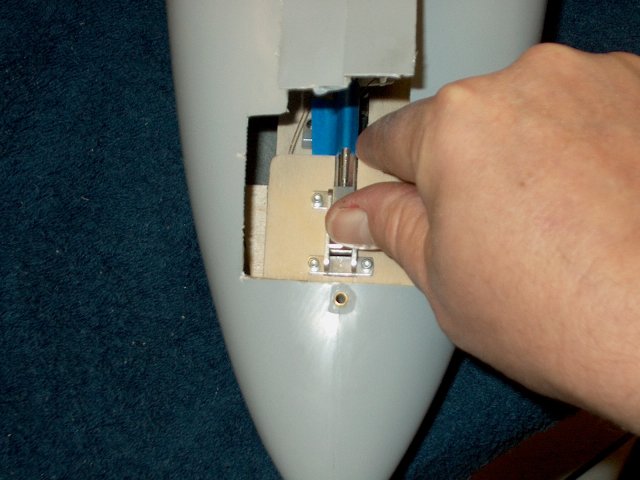
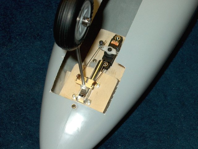
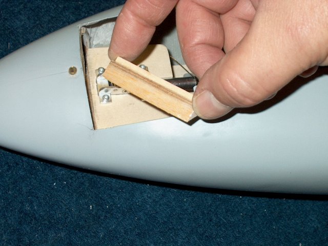
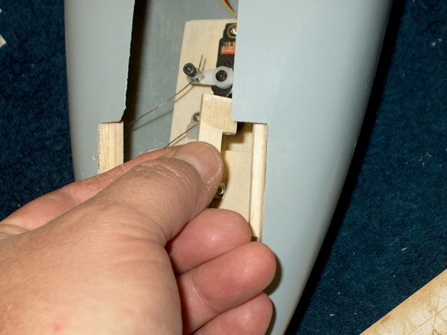
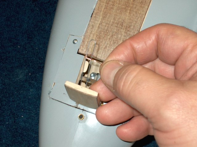
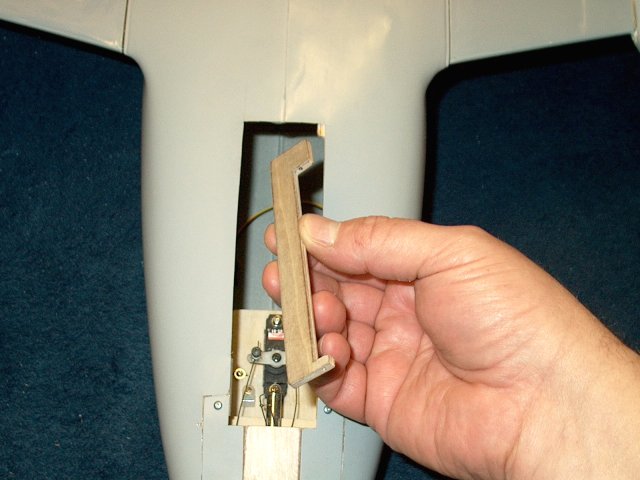
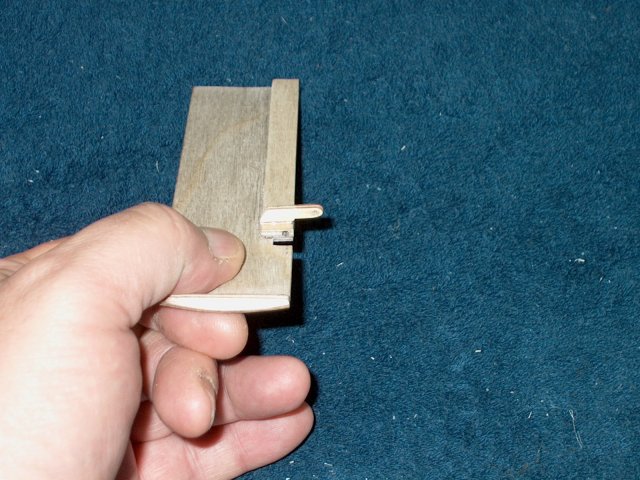
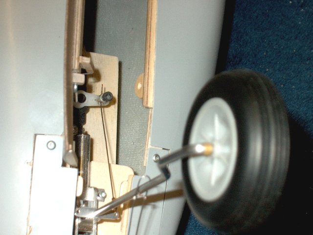
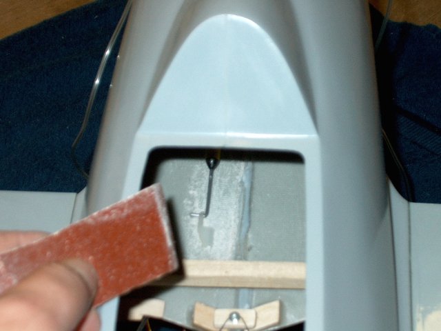
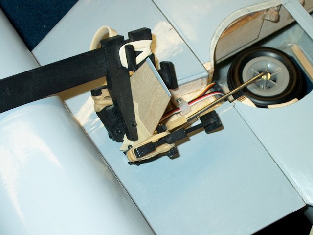
Install the secondary spar, the long wedge
and the retract and check their position. Install the fixed
gear wire in its hole and check that the angle of the retract
wire is similar to the fixed wire ash shown. Also, slightly
sand the inside of the long wedge if the retract is too
tight | |
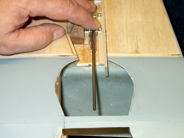
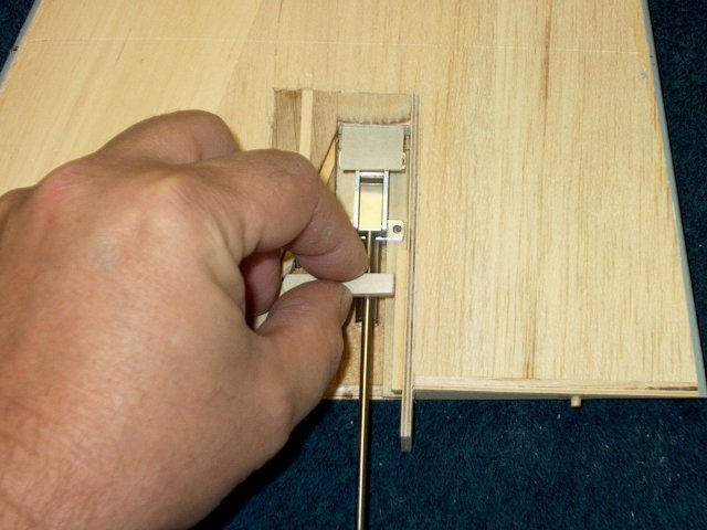
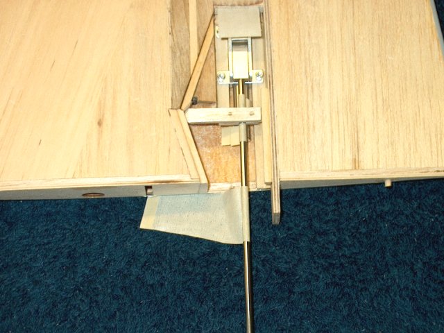
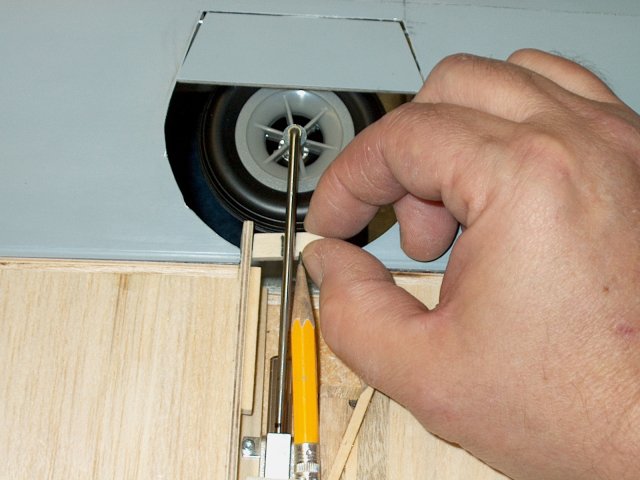
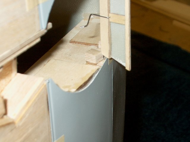
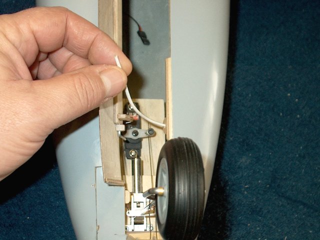
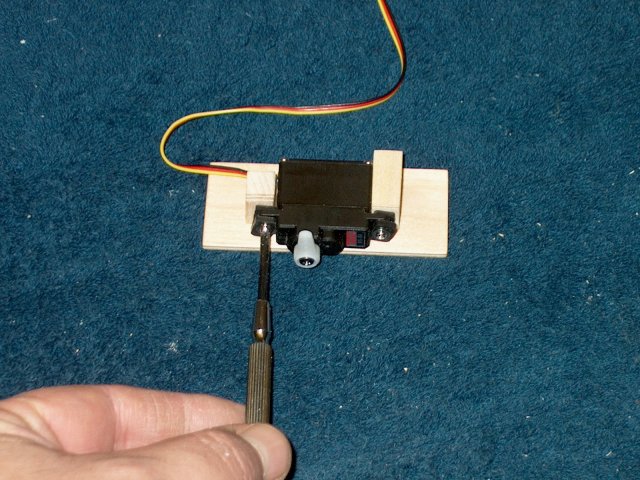
Use a screwdriver to push the roll bar
level forward in the retract and then fold the gear wire into
the wheel well. Check that the wire runs paralled to the wing
door area and that is is fairly centered in the wheel
area | |
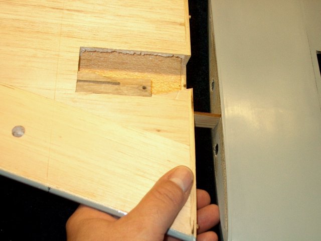
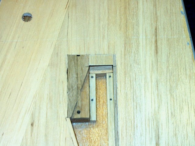
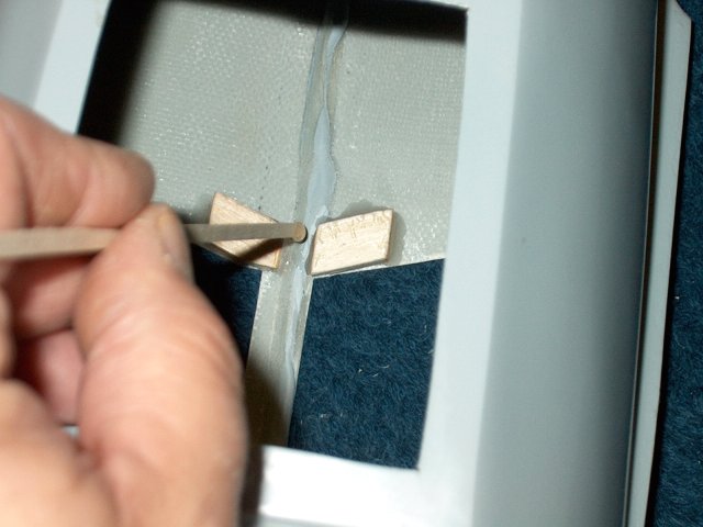
Apply epoxy to the 3/8" square block and
install in in the opening you cut so the bottom is pressed
against the inside of the root spar
| |
Use the secondary spar to hold it in place
while the glue sets. | |
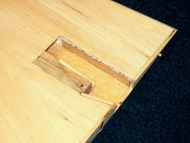
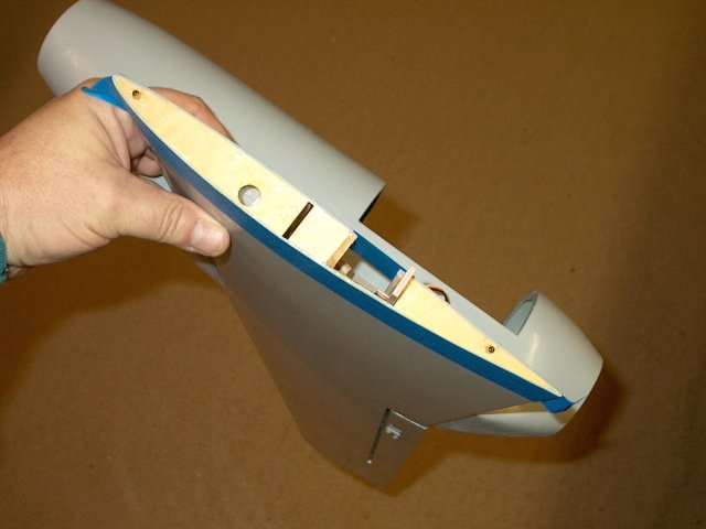
The block support is shown glued into
place | |
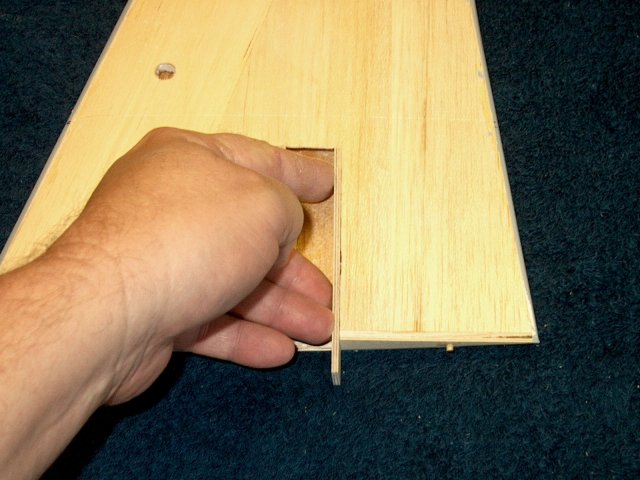
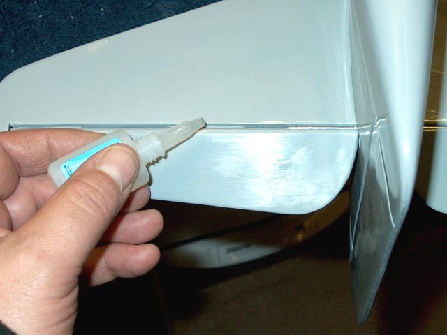
Apply epoxy to the side and bottom edge of
the secondary spar and install it in place. Do not apply epoxy
to the bottom part of the spare that is exposed and plugs into
the fuselage | |
Clean up all excess epoxy
| |
Apply epoxy to the long wedge bottom and
the one side facing the spar | |
Epoxy the long wedge in place, so the back
is even with the other wedge and the bottom should come near
the end of the wing root | |
Clean up all excess epoxy with a scraper
and paper towels | |
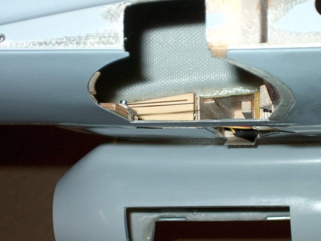
Install the AirPower RA-260 retract. It
should just fit between the two wedge blocks
| |
Cut another piece of hardwood block to fit
behind the two wedge mounts | |
Apply epoxy to the area as shown
| |
Install the cross block support and epoxy
in place | |
Clean up any excess epoxy
| |
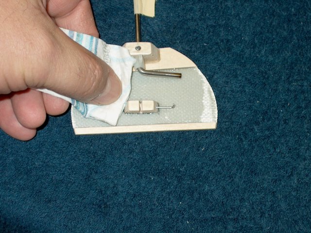
Lightly sand the secondary spar so it is
flush with the wing sheeting | |
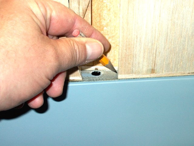
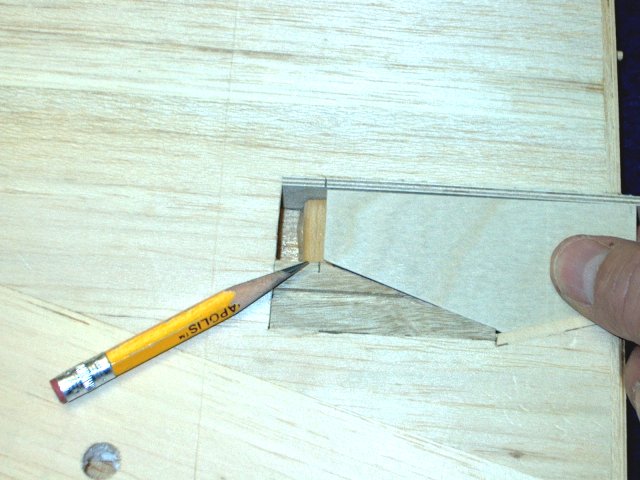
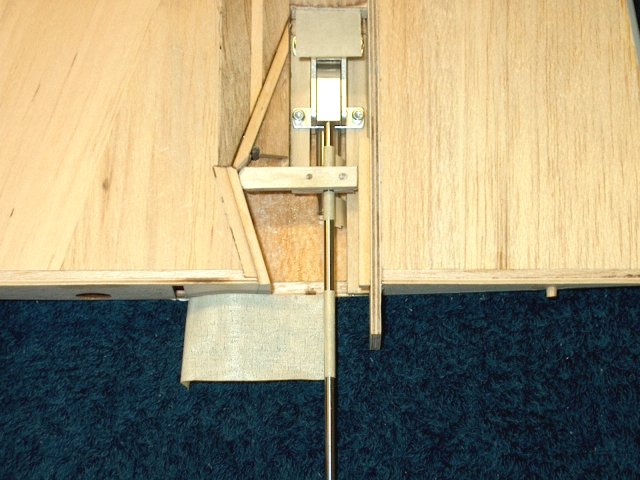
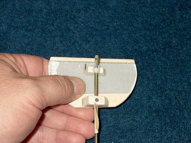
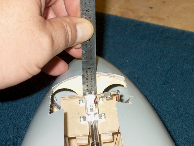
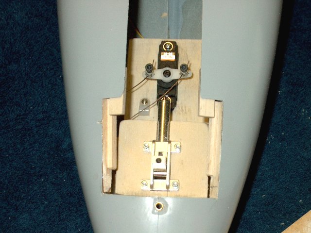
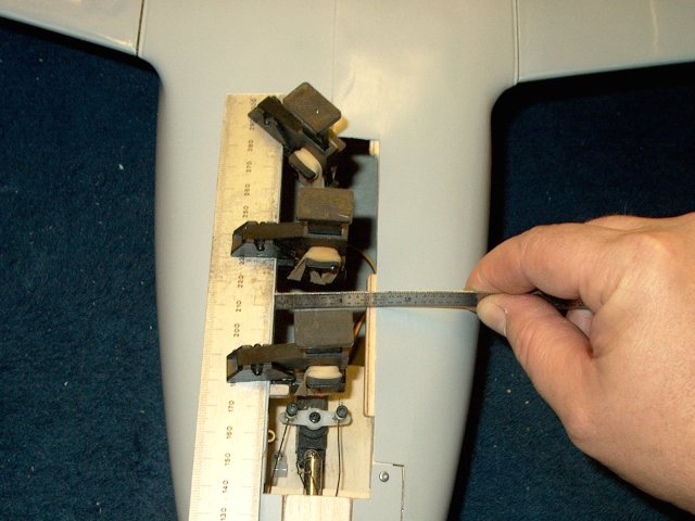
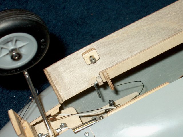
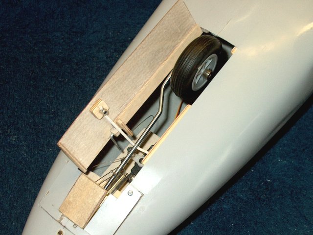
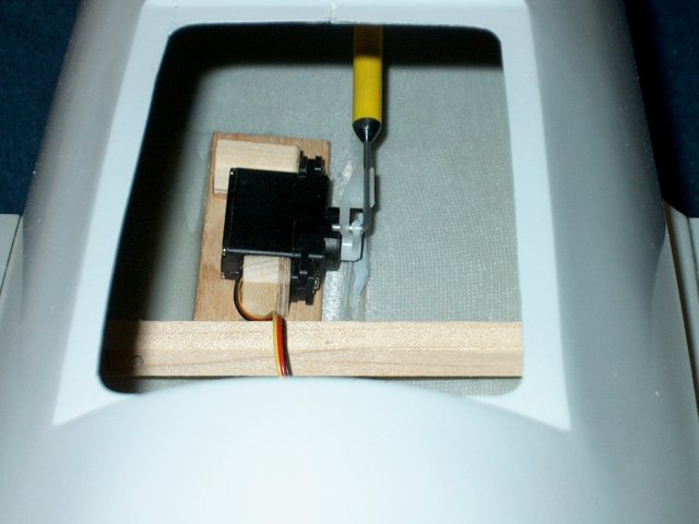
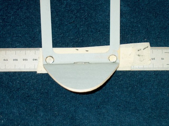
Position the retract so the front of it is
1 15/16" from the root edge of the wing as shown
| |
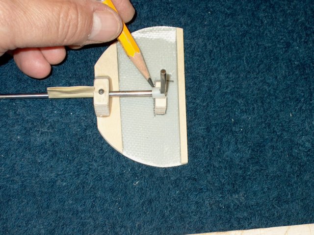
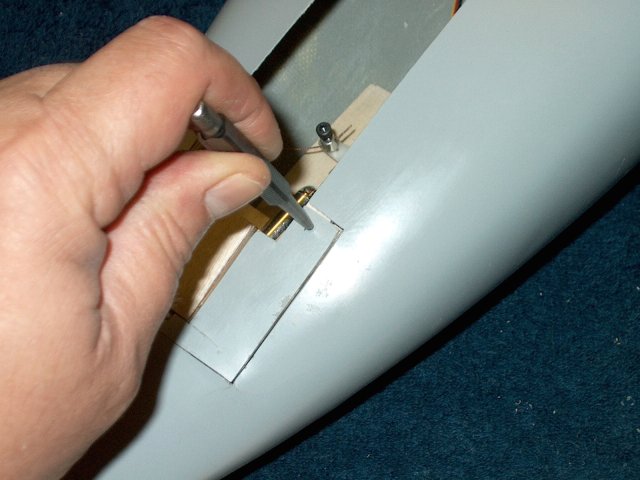
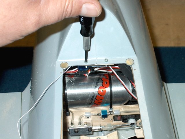
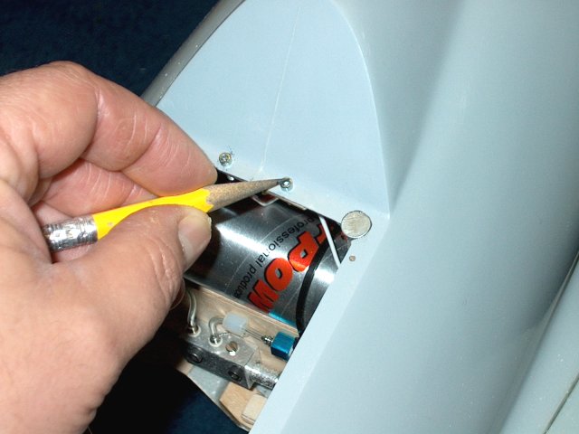
Use a pencil to mark the location of each
mounting hole | |
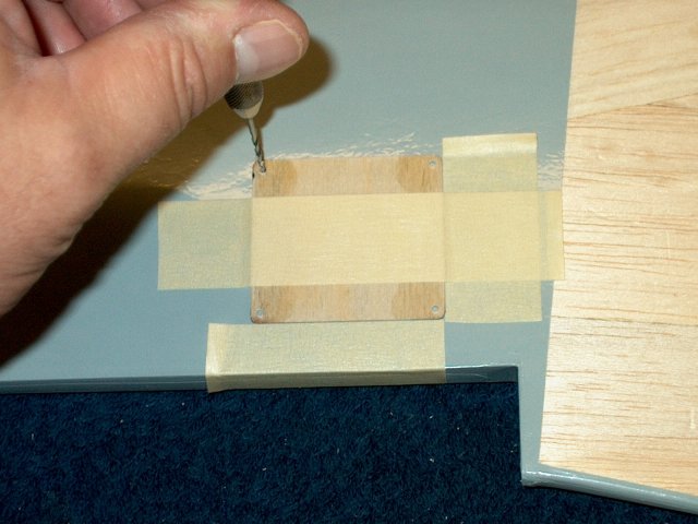
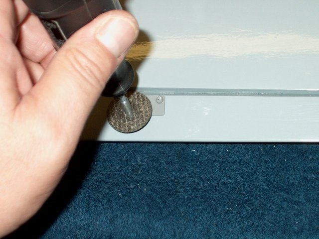
Use a punch to start the mounting
holes | |
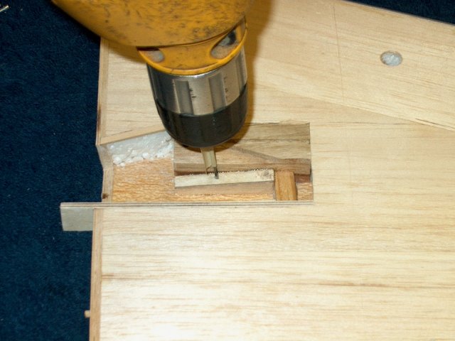
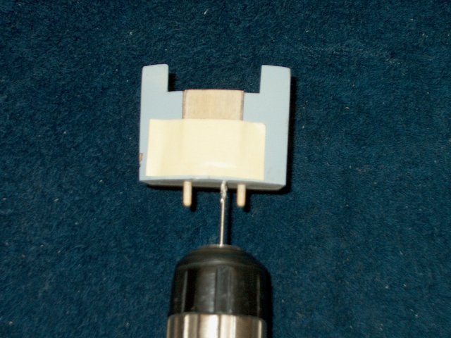
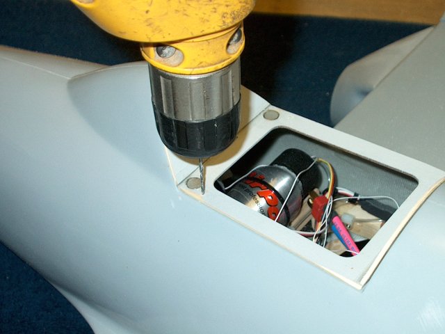
Place a piece of masking tape on the end
of your drill bit, no more than 3/8" from the end. Do not
drill past the tape as this will act like a depth gauge so you
do not drill through the top of the wing. Drill the four
mounting holes with a 1/16" drill, angling the bit from the
side view so it is perpendicular to the wedge
| |
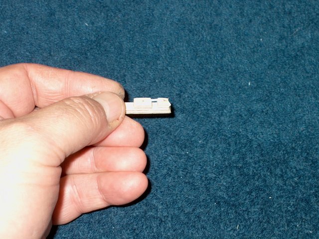
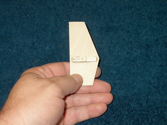
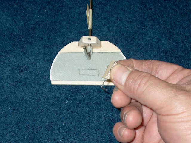
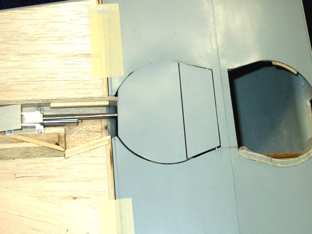
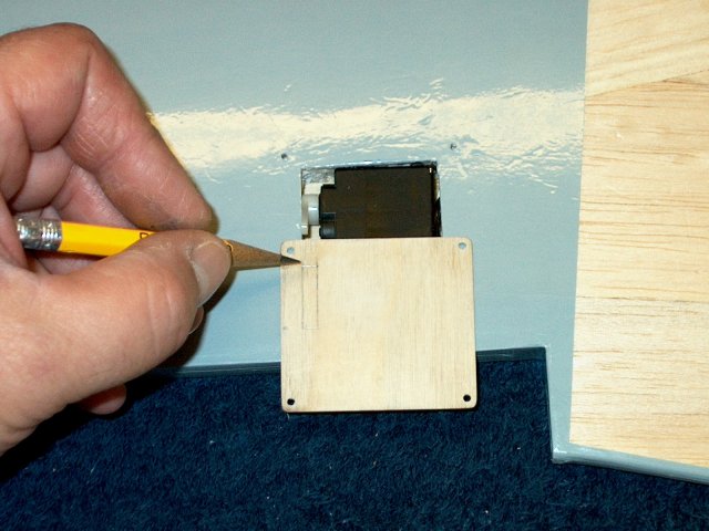
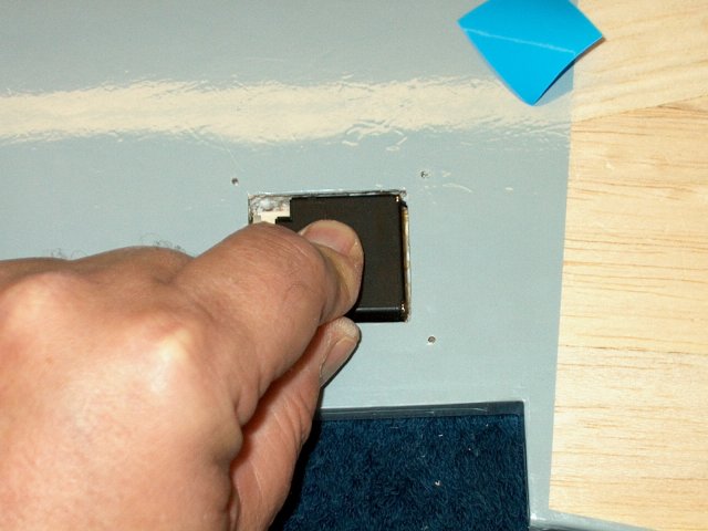
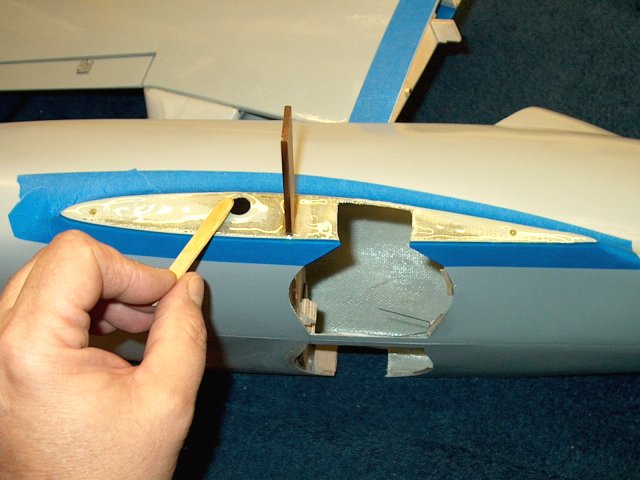
Temporarily install the door and mark its
top location as shown | |
Fit a 1/32" ply plate as shown, just above
the marks you made | |
Place a EZ-Hinge in position and mark the
areas that need trimmed down to size the hinge to the
hole | |
Measure and draw a centerline down the
hinge | |
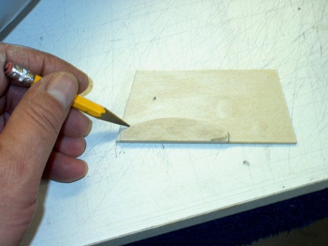
Place half the hinge over a 3/16" thick
piece of balsa and trace the outline of the hinge to the
balsa. Note that the hinge sides were cut slightly angled to
allow for clearance on the sides | |
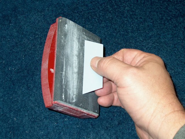
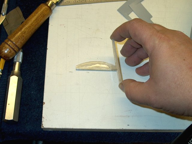
Use a ruler to scrape away and compress
the balsa topcoat on the block so the hinge is recessed and
the top of it sits flush with the balsa block
| |
Round the back bottom side of the balsa
block so that the Aileron Servo cable will not hang up when
passed by it | |
Tape up half the hinge to the centerline,
then epoxy it to the balsa | |
Cap the top of the hinge with the 1/32"
ply coverplate while the epoxy is still wet
| |
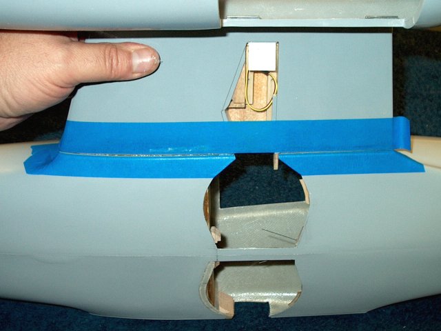
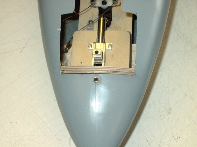
Install the block while the epoxy is still
wet under the top wing area so the front of it comes even with
the top of the door as shown. A piece of tape is used to hold
the ply plate and balsa block in position until the glue sets.
Use a ruler underneath as shown to insure the block is pressed
up against the inside of the wing | |
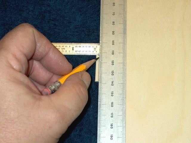
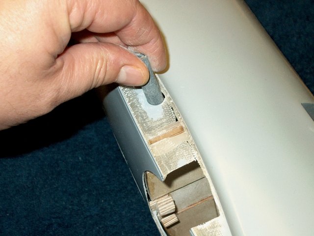
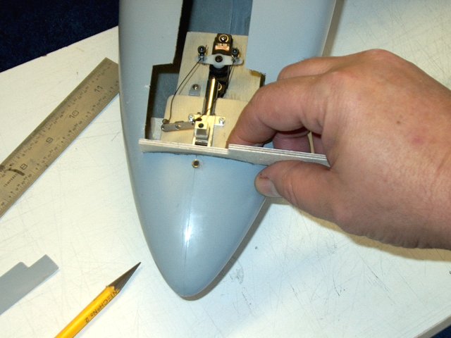
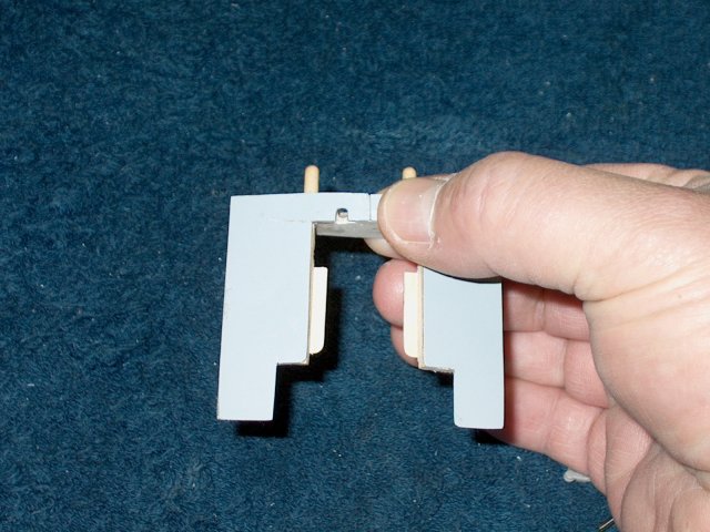
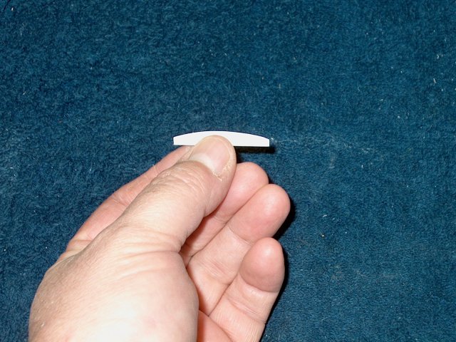
Cut a piece of 1/8" square basswood to a
length that allows the inner retract screw to still be
installed | |
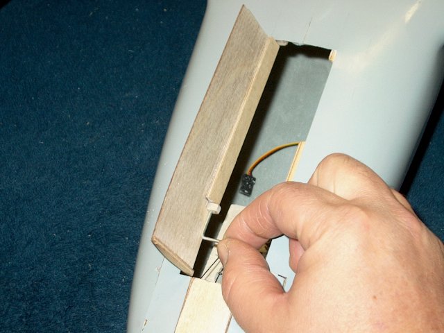
Epoxy the stick in place and use the door
to measure how low to place the stick. The top of the door
should be even to the wing's surface
| |
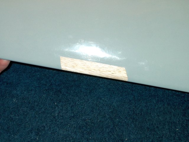
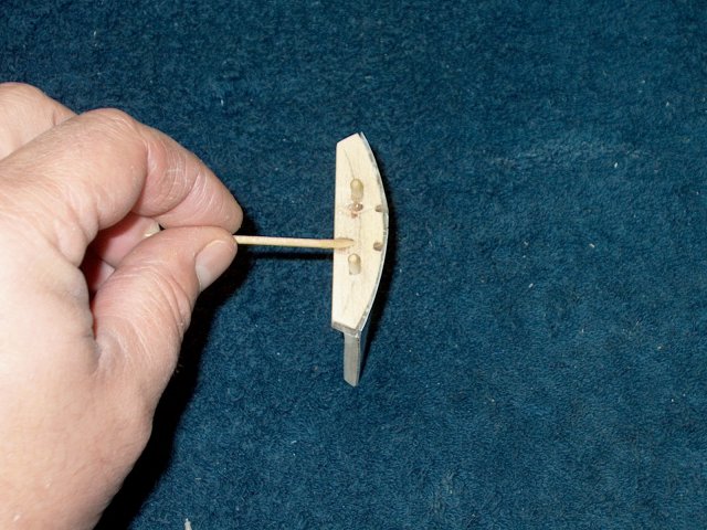
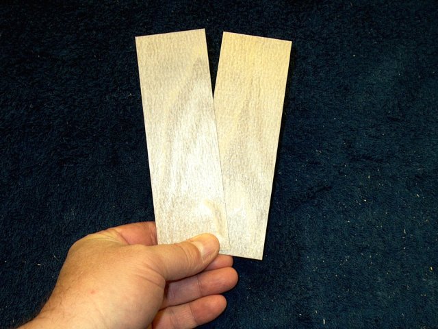
Cap the top of a scrap piece of 1/8" balsa
with some 1/8" basswood stick | |
Measure and trim the balsa plank to height
and cut to size. Make sure it sits recessed below the top of
the wing | |
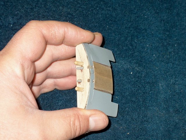
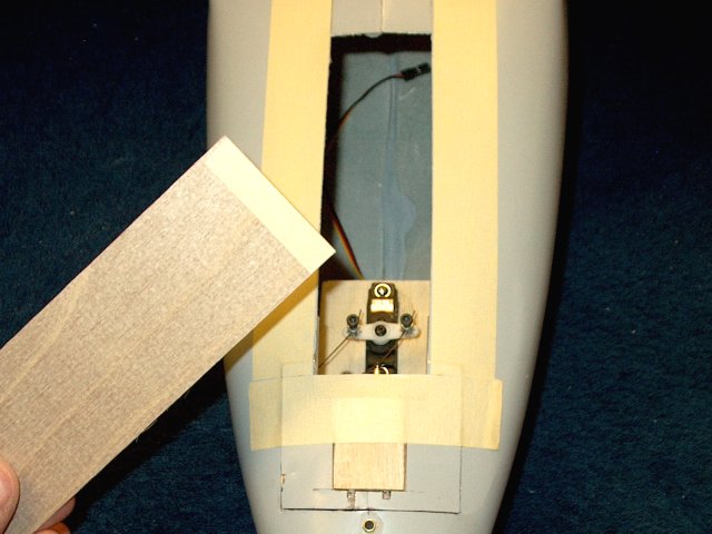
Sand a bevel at the end of the balsa
plate | |
Glue the plate in place, with the basswood
stick on top as shown. IT will cover the wing foam and should
sit recessed so the door is flush to the wing
| |
Clean up the excess epoxy. The plate will
cover the wing foam and should sit recessed so the door is
flush to the wing when placed over this stop plate
| |
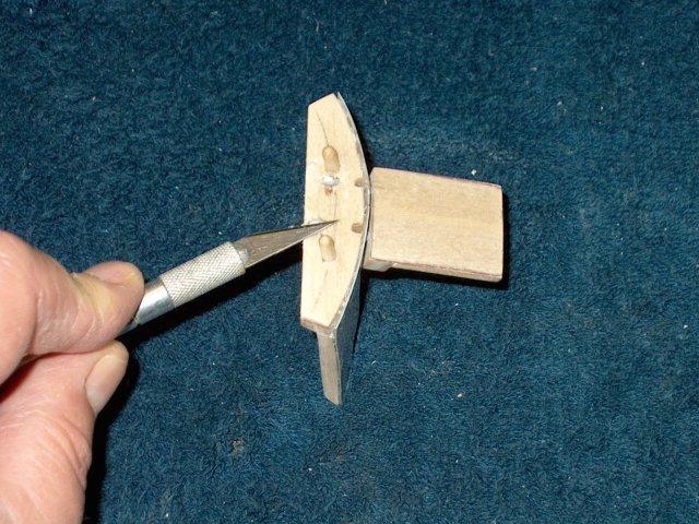
Apply some epoxy to the fixed gear slot in
the hardwood block | |

Use some scrap 1/8" square basswood stick
to fill in the space | |
Cut the excess basswood so it blends in
with the angle of the hardwood door cuts
| |
Epoxy a piece of 1/16" x 1/8" basswood
stick at the angled location to prevent the door from receding
to far, but ratheer give it a landing for which to rest
| |
Place the door over the retract area and
check for fit. It should be recessed enough to sit below the
surface of the wing. Sand the landings to fit if
necessary | |
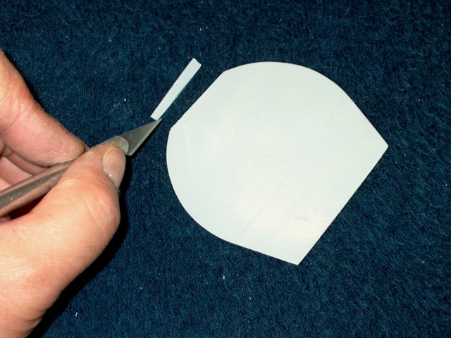
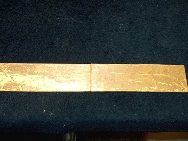
Cut a piece of 1/8" ply to a width of 1/4"
and to the length and shape as shown. this will act as door
retention and an alignment guide | |
Bevel both the front and rear inward to
allow for alignment of the door | |
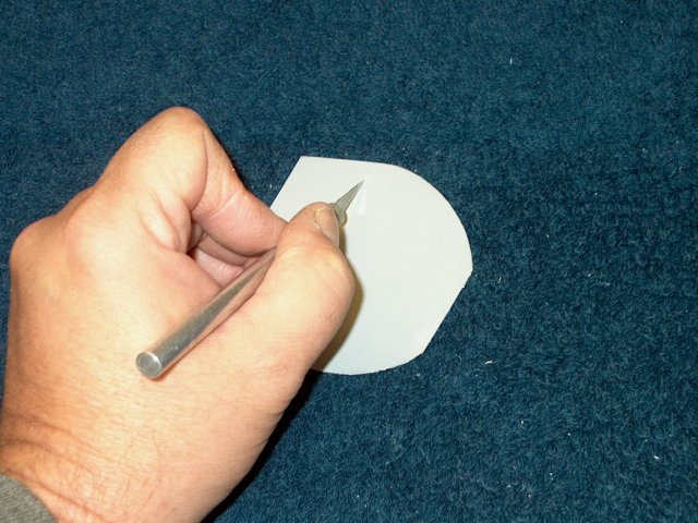
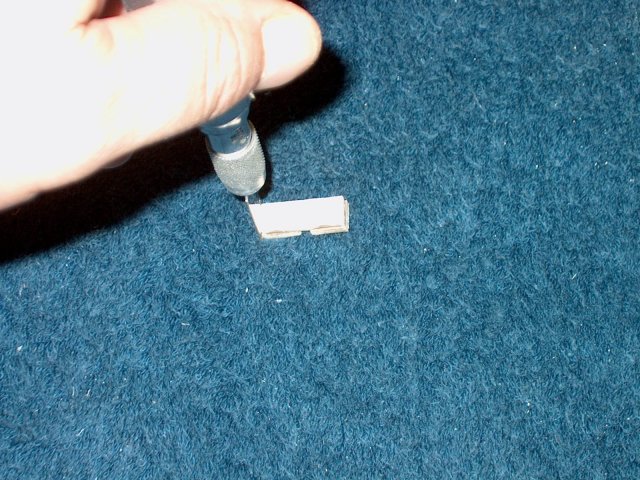
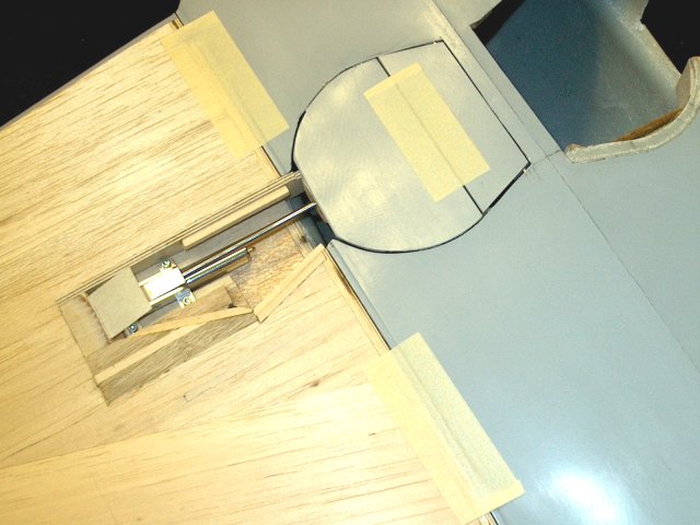
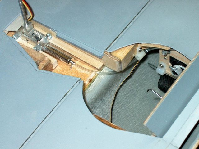
Install the retract and colapse the gear.
Rub a pencil across the top of the gear wire as shown
| |
Position the door bracket in place and
lift the gear wire | |
The gear wire transfered its location to
the bracket | |
Cut a short piece of 1/8" ply and epoxy it
in place to the back side of the gear(right)
| |
Cut a second block and use it to wedge the
gear wire between it and the other block. Apply thin coat of
CA to the top of the two blocks to prep them for
drilling | |
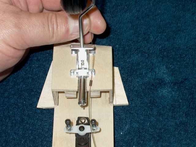
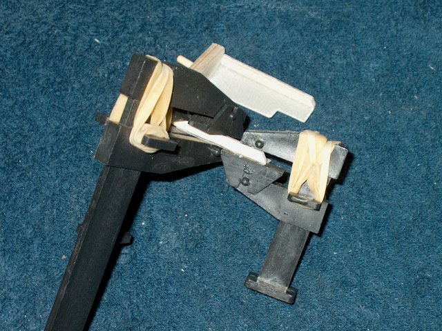
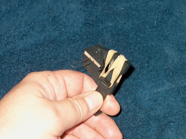
Drill 1/16" holes through the center of
each small block and out the bottom of the bracket. Epoxy a
small diameter piece of elastic cord in one hole, then when
set, epoxy the other side in, keeping some tension on the cord
so it dries while semi-taught | |
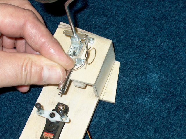
Slip the asssembly over the gear wire. Use
small pieces of masking tape to keep it from shifting position
on the wire | |
Apply epoxy to the top surface of the
bracket assembly | |
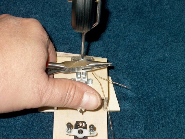
Use tape to hold the gear wire down and
out of the way | |
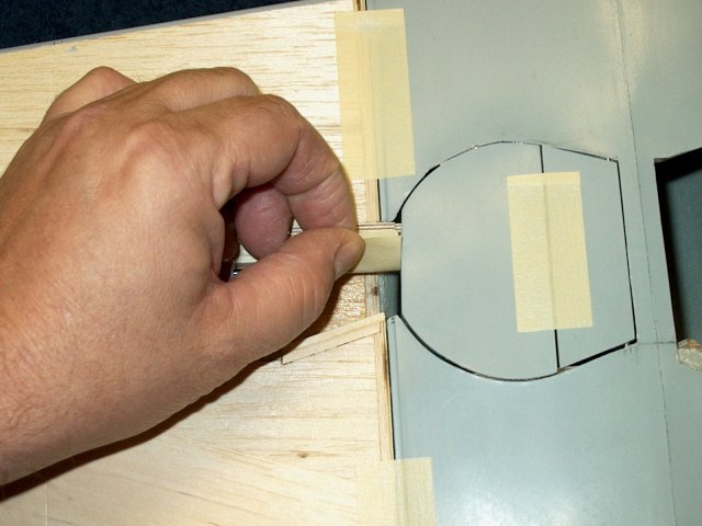
Position the door in its opening and tape
in place | |
Tape the top of the door over the
hinge | |
Lift the gear wire until the bracket
touches and glues to the inside of the door. Allow the glue to
set | |
Door Bracket is shown correctly
installed | |
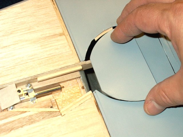
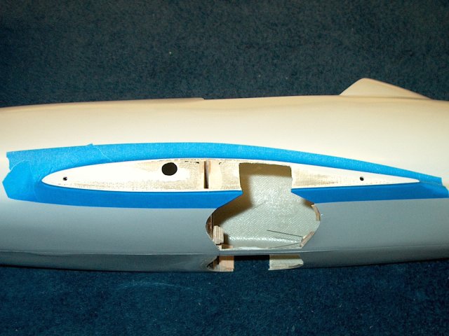
Locate the area of fuselage you removed
for the gear and wheel; this will be used as the doors. Trim
the top of the fiberglass door as shown and keep both
pieces | |
Measure 1" from the inside flat area of
the door and cut the smaller door away from the larger
| |
Lightly sand the smaller door to smooth
the ends | |
epoxy a piece of 1/16" thick ply that is
1/16" wide along the short side length of the door
| |
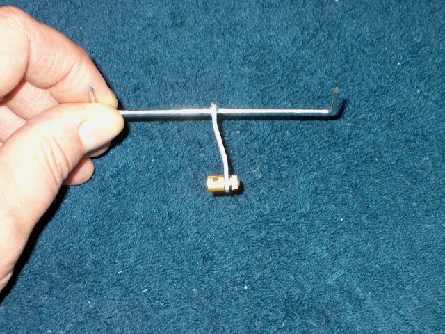
Make a wire hinge from 2-56 pushrod and
bend as shown in the templates | |
Place the wire in position as shown and
cut an inner 1/16" ply piece at least 1/8" wide. It will be
placed above the wire to wedge and hold the wire in
place | |
Cap the assembly with a final piece of
1/16" thick ply wide enough to cap the assembly
| |
Ply ends are shown glued in place
| |
Mark a center line on the wide ply plate.
Use a saw to slot only down to the hinge.
| |
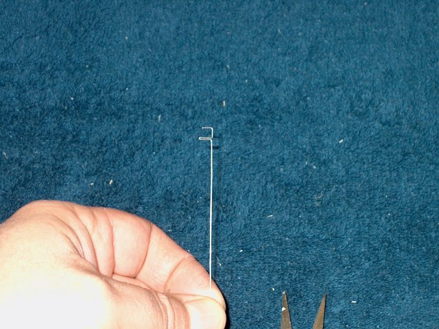
Bend a piece of micro pushrod as
shown | |
The pushrod is a fraction longer so it can
push into the thin ply brace at the bottom, then slide into
the slot you cut with a saw as shown at the top
| |
Cut a small piece of 1/16" thick x 1/4"
wide ply so it fits between the two ply braces. Slot it so it
will cover the micro wire | |
Epoxy the short ply over the micro wire as
shown | |
Bend the wire 1/14" past the rear of the
door | |
Position the door temporarily in place.
Remove any fuselage glue that will get in the way over the
next few steps | |
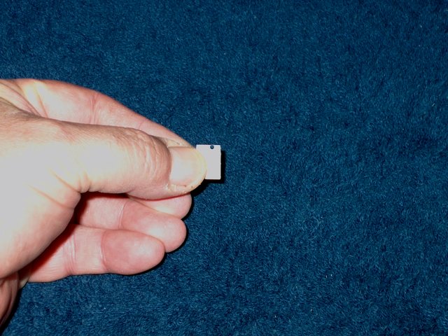
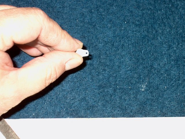
Cut a piece of 1/8" thick ply to 3/8" x
1/2" in size and drill a 1/16" hole on one end as shown
| |
Cut the rear hinge bracket from the
template and glue the bottom side with a thin piece of 1/16"
ply, followed by the hinge rod and capped with another piece
of ply. | |
Remove the excess ply from the bracket
witha saw | |
Rear hinge shown ready to install
| |
the wheel door is prepped by adding a
strip of 1/16" thick x 1/8" ply to the long edge
| |
Epoxy the wood strip to the door
edge | |
Clamp and hold flat the glued side as the
strip of wood can be used to remove any warping in the glass
door | |
Cut a 1/16" x 1/2" wide strip of ply and
shape the ends to the contour of the wheel door
| |
Once again, epoxy the strip in place,
clamping to a flat surface so it reshapes the door and removes
warping | |
Sand the ends of the ply barces flush to
the glassed door | |
Install the wire hinge on the fuselage
door | |
Sand the inside of the fuselage to allow
for good glue purchase | |
Center the door in its location and use
masking tape to hold it in place | |

Apply epoxy to the rear hinge ply bracket,
but keep the slot free of epoxy | |
Position the bracket in the fuselage and
over the hinge wire using a knife to hold the piece
| |
Apply fillets of glue along the sides of
the hinge bracket | |
Remove any excess epoxy from the fillets
and once the glue begins to set, twist the wire hinge so it
doesn't get glued in position and can be removed later
| |
Apply epoxy the the forward ply
hinge | |
Epoxy the forward bracket in place and
push the hinge rod through the hole in the bracket. Reposition
the bracket so the door is spaced evenly in the fuselage and
let the glue set | |
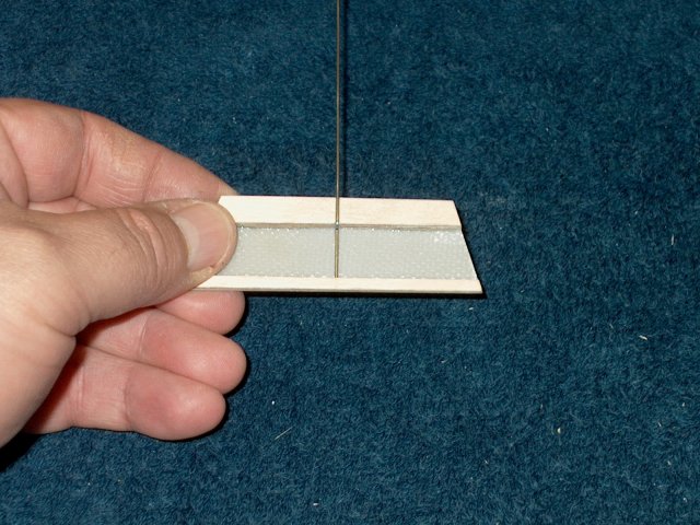
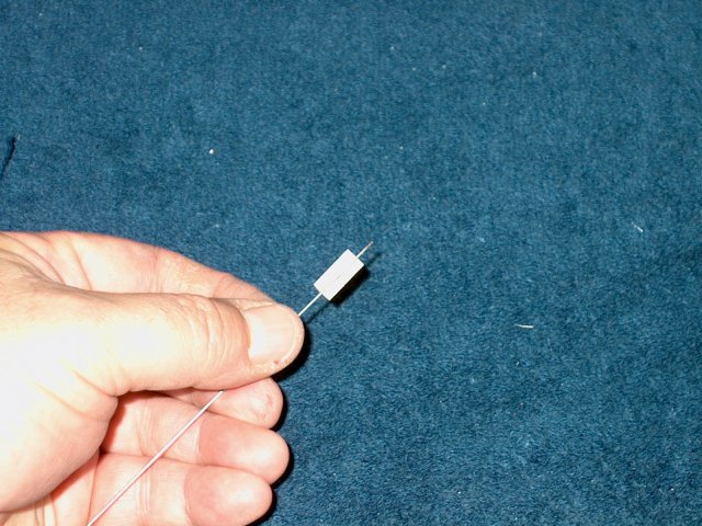
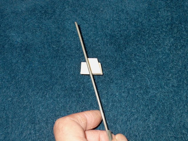
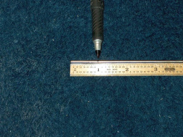
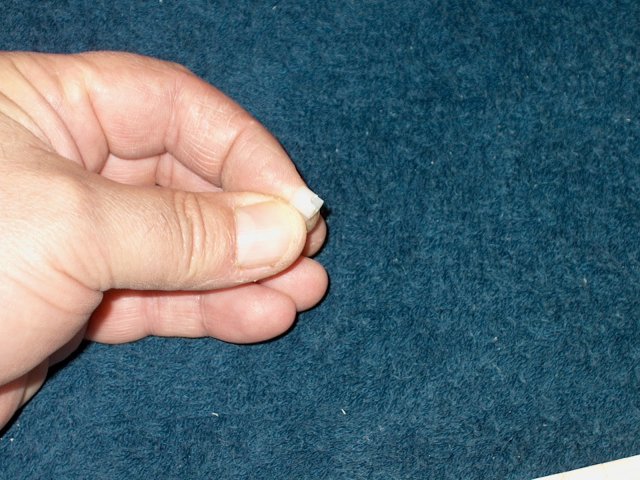
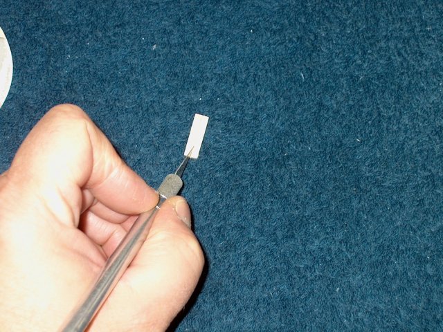
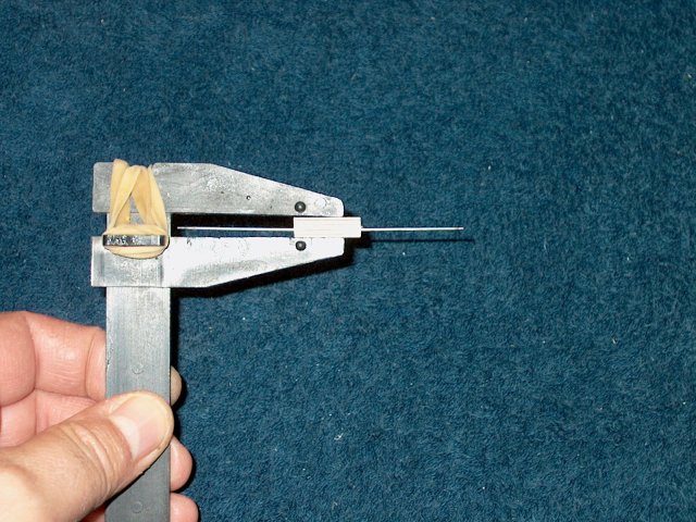
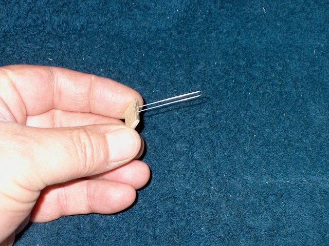
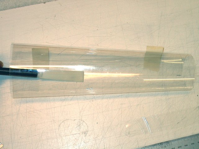
Cut a piece of 1/8" inner diameter brass
tube to the length of 5/32" as shown
| |
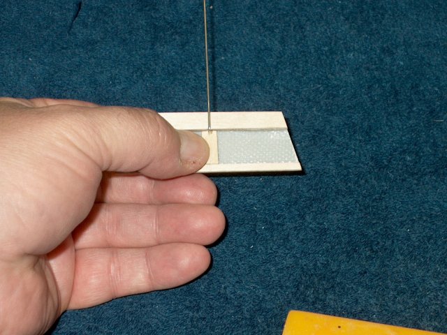
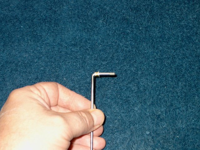
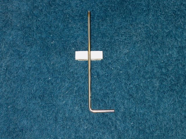
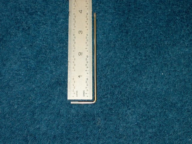
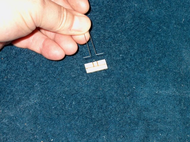
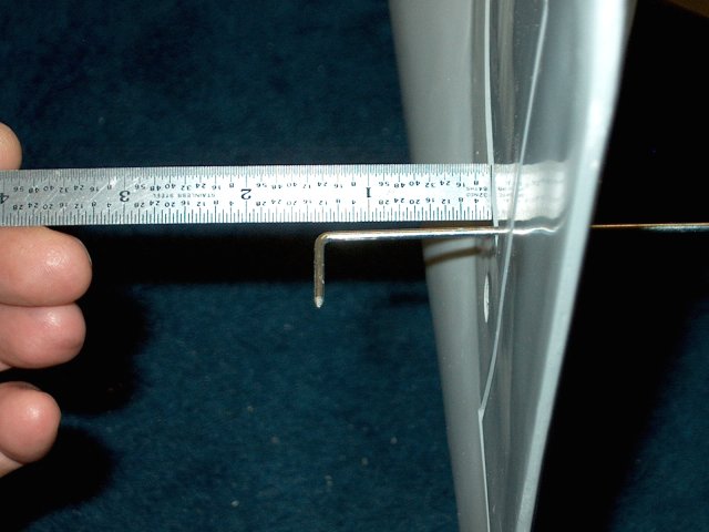
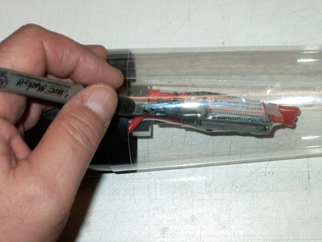
Mark the landing gear wires at 1" from one
end | |
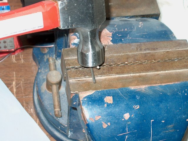
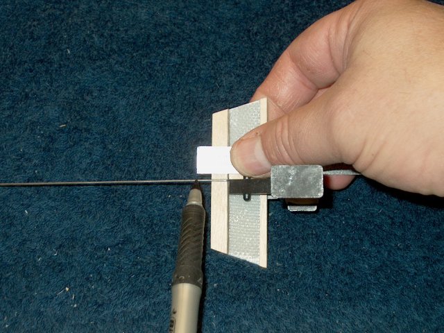
Using a vise and hammer, bend right angles
on each rod at the 1" mark as shown. You can tape the wires
together side by side to make sure they are even to
eachother | |
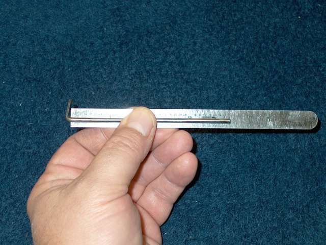
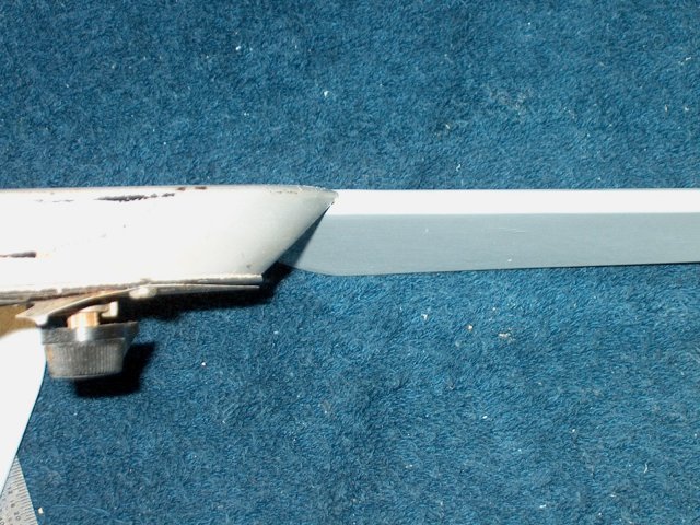
Once bent, measure the length of the wire;
it should be 4 inches | |
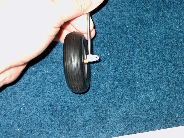
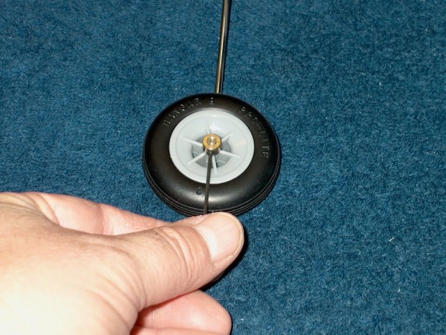
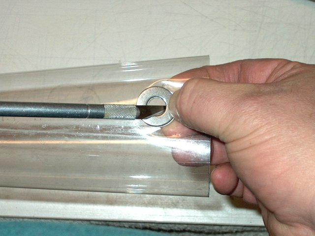
Install the brass tube over the wire,
which is a spacer for the wheel, then install a 4-40
washer | |
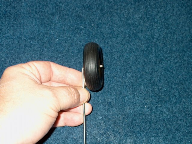
Install the wheel and finally the supplied
wheel collar | |
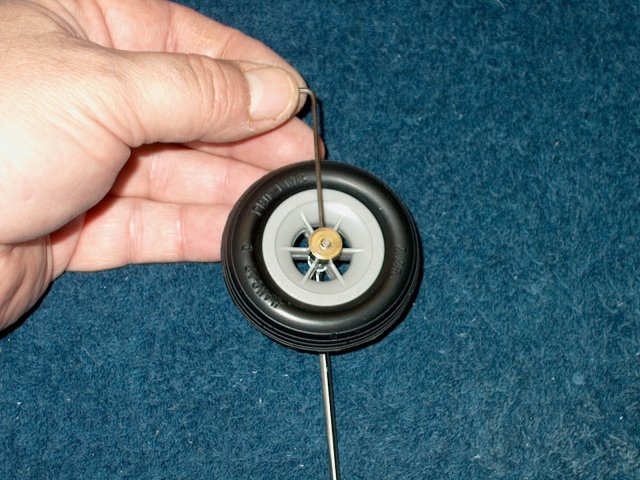
Tighten the wheel collar and make sure the
wheel spins freely with no binding | |
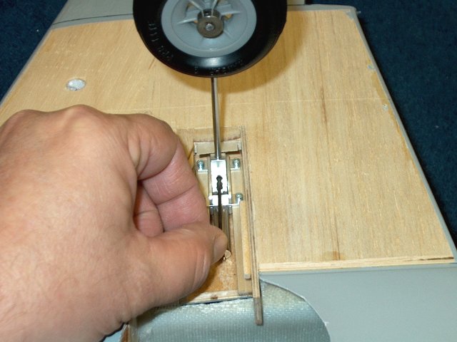
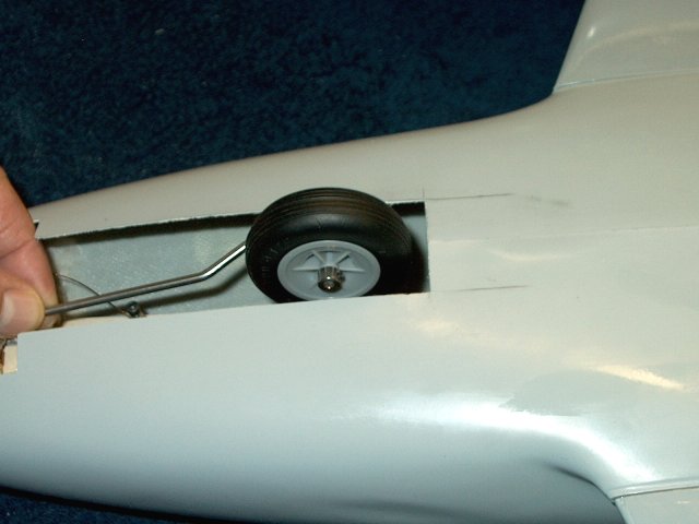
Install the gear wire in the retract
assembly | |
Fold the gear over and check for
clearance | |
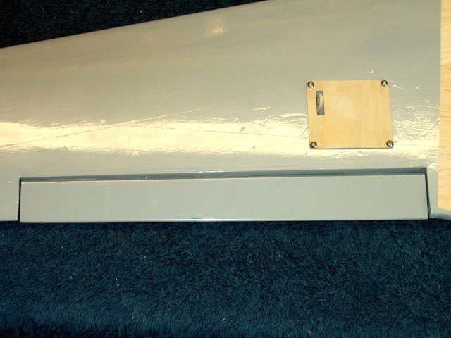
Install the short door on the
fuselage | |
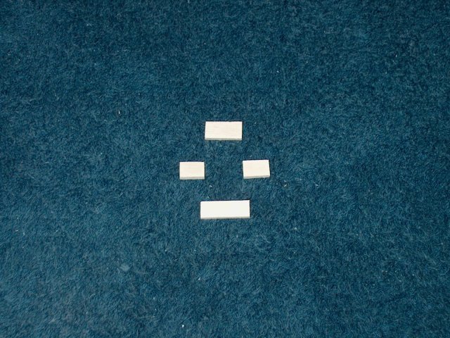
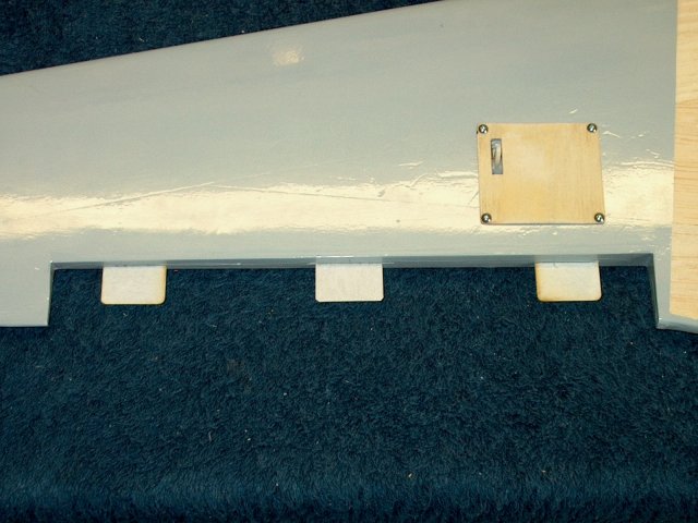
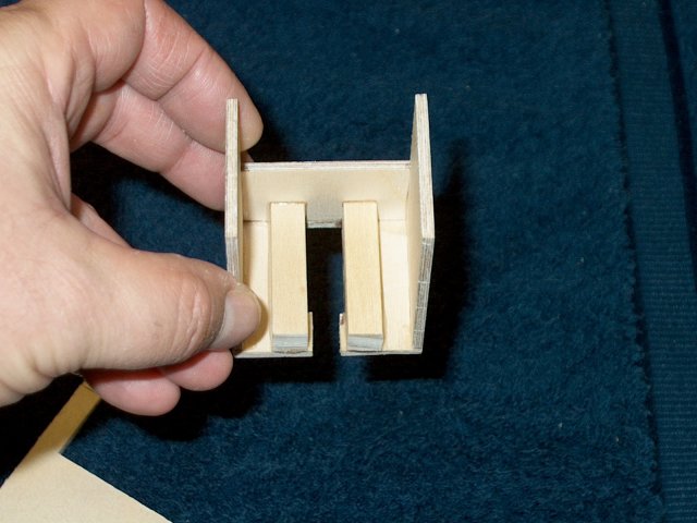
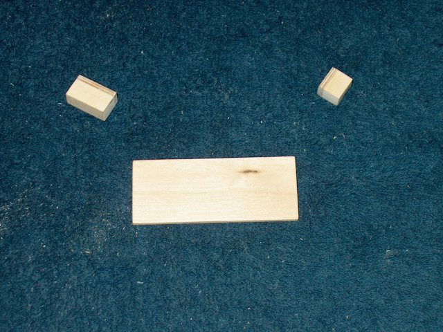
Cut three pieces of 1/8" ply to a width of
5/16" and length of 7/8", then split the center piece in
half | |
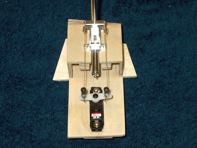
Place one of the ply pieces under the gear
and flush to the secondary Spar, then mark the wire side
locations on the ply | |
Epoxy the two short pieces at the
locations, using a 1/8" wire to gauge for a snug fit
| |
Remove the excess ply from the center
pieces that are hanging over the ends
| |
Epoxy the third ply piece in place,
centered over the assembly | |
Sand the bracket to shape, beveling the
edges as shown. The bevel will act as a guide against the
Secondary Spar and keep the wheel aligned when
retracted | |
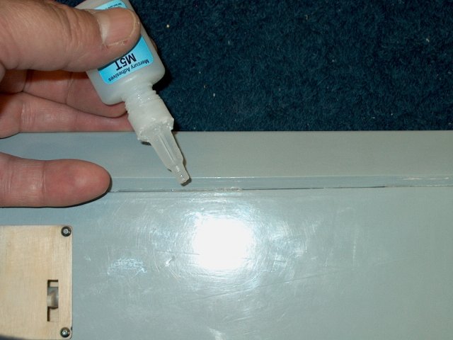
Apply a coat or two of thin CA over the
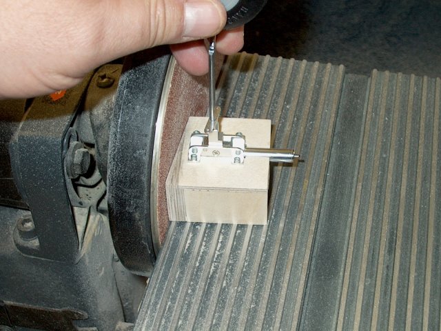
top of the bracket | |
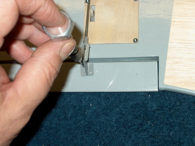
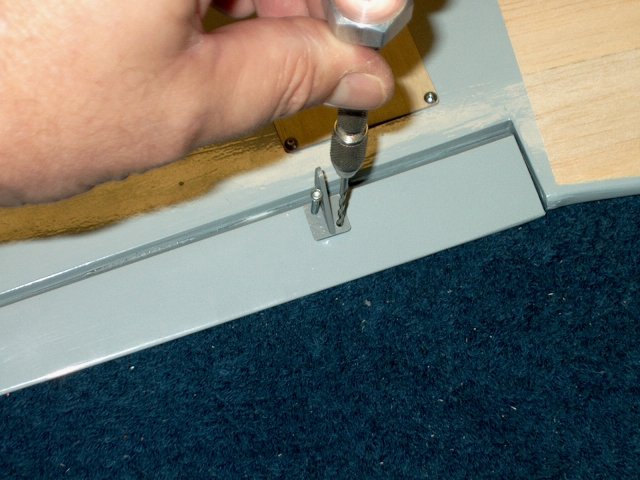
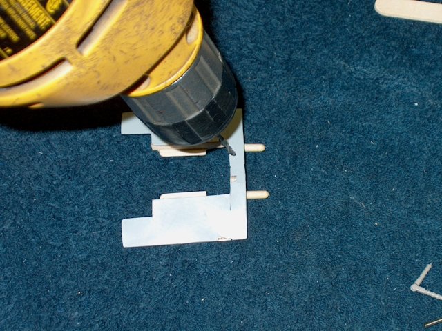
Use a 5/64" drill to make a hole dead
center over the assembly. Only drill through the top piece of
wood | |
Use a 4-40 Tap to make threads in the wood
hole. Add a couple drops of thin CA to harden the threads and
tap once again when the glue has dried
| |
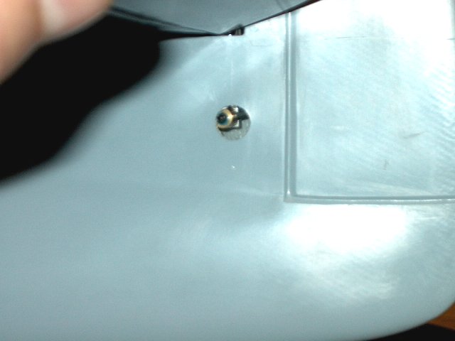
Install a 4-40 set screw in the tapped
hole | |
Use a scrap piece of 1/32" ply and draw
the curve of the wheel opening on the ply
| |
Cut out the piece 1/2" wide and 3/4" long.
Shape and sand/round the corners | |
Make a mark on the fuselage 1/2" from the
short door as shown | |
Epoxy the 1/32" ply stop plate in position
and line up the side with the mark for proper spacing
| |
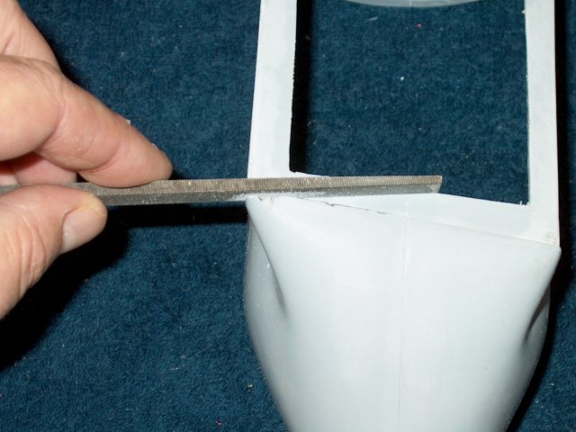
Use a file to sand down the top area of
the secondary spar as shown so that the wheel door will sit
flush with the fuselage | |
Check to make sure the door sits flush
where you notched the spar | |
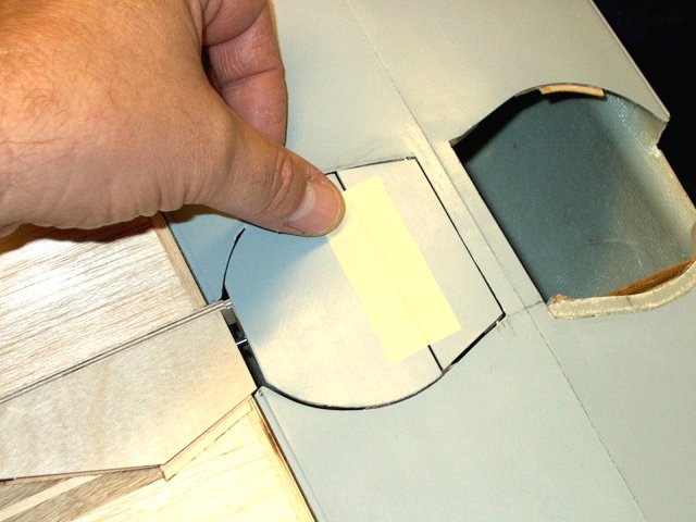
Space the round door evenly in the opening
and then tape it to the small door to hold it in place
| |
Flip the door out of the way and apply
epoxy to the upper bracket as shown. Check that the position
of the bracket is high enough so it won't rub against the
wheel | |
Flip the door back over and press it down
on the bracket with epoxy. Allow some time for the epoxy to
set | |
Lift the door once the epoxy initially
sets and allow the glue full set time.
| |
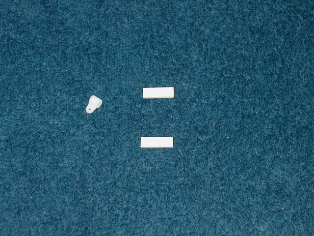
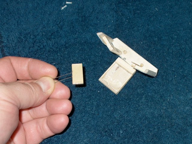
Cut the two lower door mount pieces from
the templates. They are 1/8" thick ply x 1/4" x 3/4" long and
you will also need a 1/8" diameter horn bracket
| |
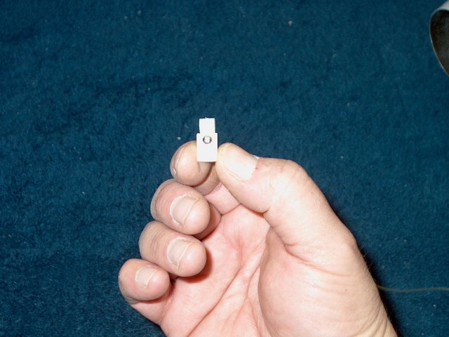
Notch the top of the horn bracket as shown
so it cannot twist on the elbow of the wire gear
| |
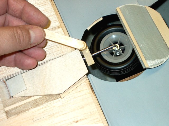
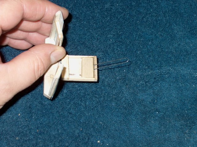
Slide the horn bracket in place as
shown | |
Install the gear and close the assmebly.
Adjust the position of the wheel door and lock it in place
with tape when centered | |
Use masking around the shaft so the door
cannot slide out of position | |
Remove the wheel, make sure the door is
slid against the tape on the left, then check the position of
the bracket horn | |
Draw a center line down one of the ply
lower mount pieces | |
Slot the top of one of the lower door
mount ply pieces so a micro rod sits in the slot flush with
the top of the ply surface. Scraping with the micro rod works
well for this task | |
Use epoxy to glue the two pieces as shown,
using the wire as a guide. Be sure to remove the wire before
the epoxy sets | |
Sand down the end of the bracket to about
half its thickness and round the end when done
| |
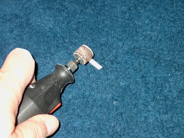
Use a dremel to cut a slot in the top
center of the mount. NOTE: The top part of the assembly is the
ply piece that was NOT slotted for the micro rod. The slotted
piece is on the bottom | |
A file is used to widen the slot so the
plastic horn bracket fits | |
The slot will need to be cut deep so that
only one layer or so of ply remains
| |
Use a dremel and sanding drum to bevel the
ends of the assembly. Lightly sand all edges to round
them | |
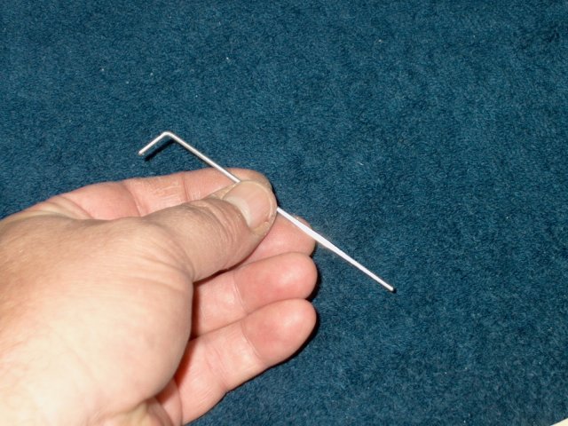
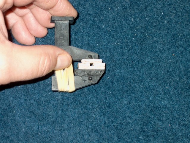
Install the horn bracket in the assembly,
then pin it in with a piece of micro wire. A small "L" shaped
handle can be bent in the wire to aid with installation
| |
The assembly allows for some pivoting of
the bracket horn so you can adjust the position of the
door | |
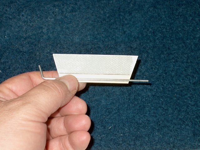
Place the mount assembly on the wire, make
sure the tape on the left of the wire is flush with the top
door mount and then use a pencil to transfer the location of
the mount to the door. Make a small mark on the top of the
mount to indicate direction so it doesn't get flipped around,
which could cause alignment problems
| |
Move the wire out of the way, then apply
epoxy to the bottom of the lower mount
| |
Install the mount and clean up any excess
epoxy | |
Install the assembly and adjust the door
position, then use the set screw to lock it in place.
| |
you can adjust the door so it is centered
in the fuselage well | |
The door closing wire is bent to work as
shown. Adjust the wire so the door closes and does not hang on
the wire | |
Find the short piece of fiberglass you cut
from the top of the round door and sand the inside curve so it
is flat | |
Tape the wing door in place
| |
Apply epoxy to the short glass
piece | |
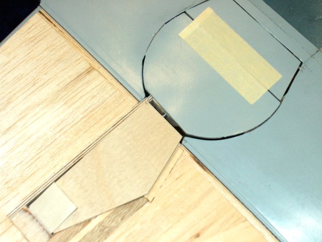
Install the piece to fill in the gap
between the wing door and wheel door and leave a small space
between them as shown | |
Build the door stop assembly from the
templates. It consists of two pieces of 1/8" ply
| |
Use the wheel to adjust the angle of the
inner door while open, allowing ample clearance for the wheel.
Place a piece of masking tape behind the door so it only opens
as far as needed | |
Epoxy the door stop in place as shown.
Close the door to make sure the stop is not too high. you can
treat the door area and stop with CA to harden them and extend
wear | |
Once glued, the extra wood can be removed
with a drum sander so the door stop is shaped as shown
| |
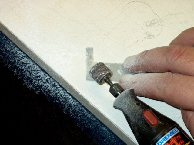
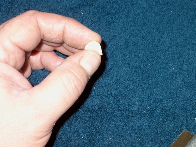
Cut the Door Spring pattern from the
template...it is a piece of ply 1/8" thick by 1/4" wide x 1"
long | |
Make a centerline down the length of both
sides of the ply | |
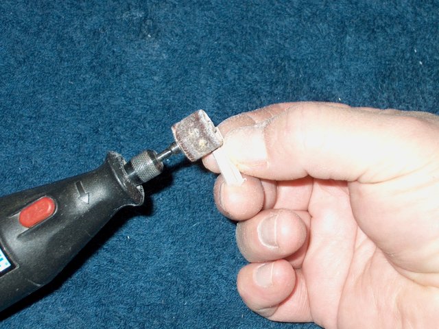
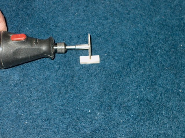
Grind the lower side to a bevel, from the
bottom of the wood to the line at midpoint. Repeat for the
other side of the wood | |
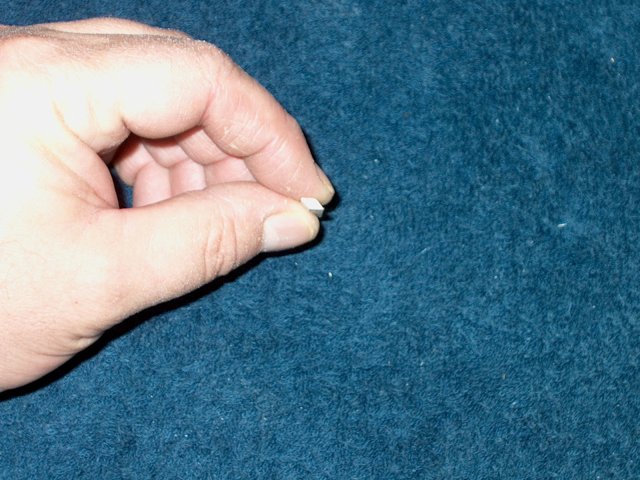
Your goal is to wind up with a piece that
is diamond shaped as shown from the side
| |
Mark and cut the piece in half so you wind
up with two 1/2" long mounts | |
Epoxy the mount to the rear of the door,
making sure the bottom of the mount starts above the seam of
the ply and fiberglass door, otherwise it will bind with the
fuselage | |
Sand a piece of plastic antenna tube to
rough up the outside | |
Cut two 1/2" long pieces of antenna tube.
Note it is easier to do both doors at the same time
| |
Epoxy the tubes to the upper back side of
the doors and add fillets as necessary
| |
The door closing wire is bent to work as
shown. Adjust the wire so the door closes and does not hang on
the wire | |
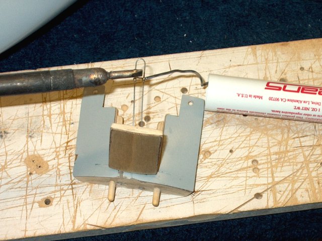
Bend a small piece of fine music wire to
the shape below | |
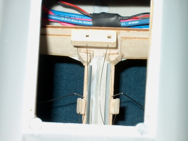
A wood block is cut and drilled through
the top through the front of the bar at two locations for the
inner fuselage door tensioning wires. It is glued in place as
shown, then fine .020" wire is cut and routed to the door
tubes as shown. These doors work similarly to the main
nosegear door, so that they spring open and closed
| |
Install the doors, making sure you thread
the wire through each door spring tube. Once installed, cut
the wires to length. Bend the wire to adjust tension...each
door should open completely against their stops as
shown | |
Mark the wing location for the
nacelle | |
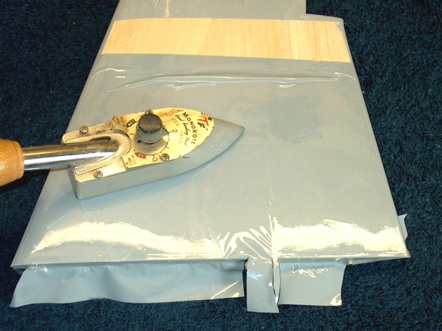
Cover the wing with iron-on material. You
can either reuse the old covering or iron on new
material | |
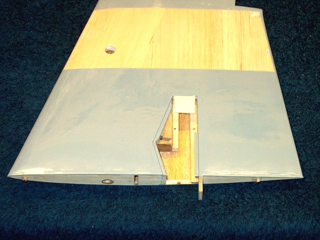
Cut out the door area and dress it as
shown | |
Make sure you removed the covering from
the top side of the wing, where the nacelle overlaps
| |
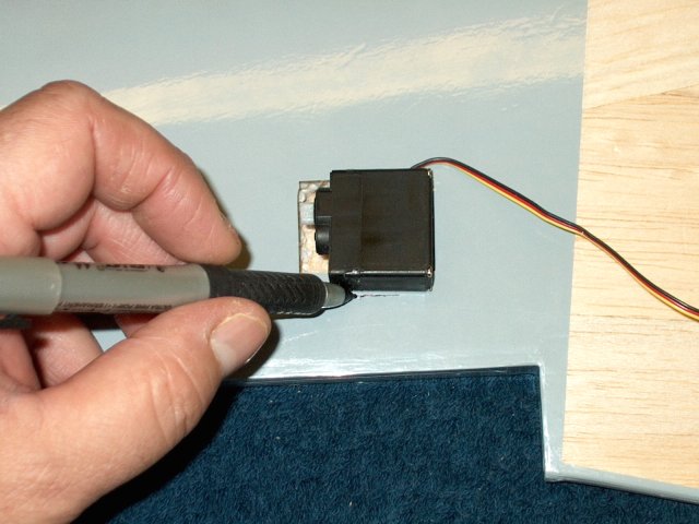
Check the Aileron servo opening and mark
as necessary to cut to size | |
Cut the servo area to fit the particular
servo you plan to use. HS-81's were used in the photos
| |
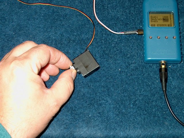
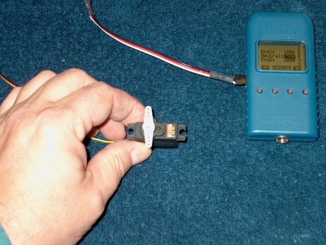
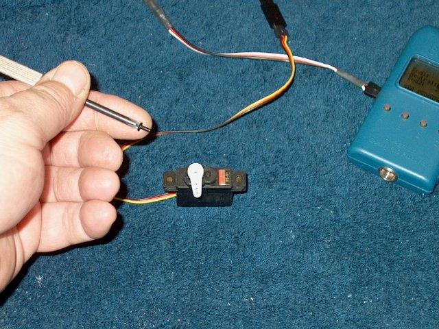
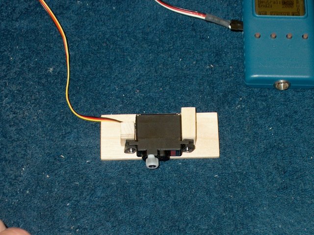
Center your servo using a receiver or
servo tester, then cut and install the long horn as shown,
then install the retention screw | |
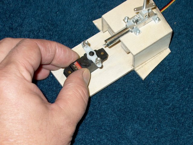
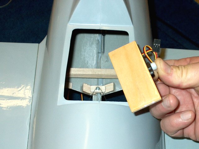
Test fit the servo in the well and make
sure it clears at the horn end | |
Cut a piece of 1/32" ply to the dimensions
in the templates for the Aileron servo ply mount
| |
Glaze the top of the ply with CA and sand
to a smooth finish | |
Apply epoxy to the bottom of the plate and
epoxy the ply servo mount to the wing as shown
| |
Make a cover for the servo from 1/32" or
1/64" ply. It is easier to make both covers at the same time.
Apply thin CA to the top and bottom corners so the wood
doesn't splinter when drilled | |
Tape is used as a guide to position the
cover. There should be about 1/4" of clearance around the
sides of the cover | |
Tape the cover in place and use a 1/16"
drill to make holes at each corner, about 1/8" in from the
ends | |
Remove the cover and mark its location and
direction as shown so they don't get mixed up later
| |
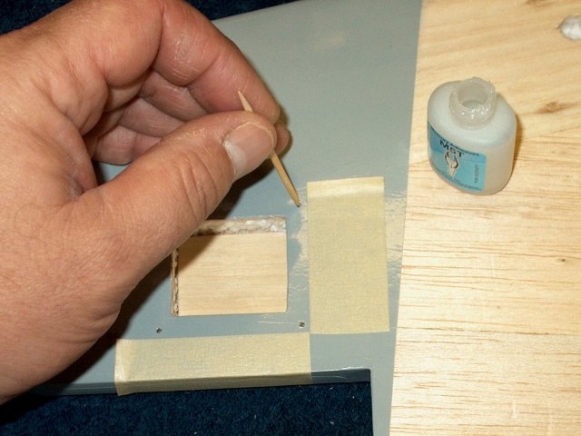
Apply thin CA to the wing holes with a
toothpick | |
Open up the holes in the corners of the
ply with a 5/64" bit so they are large enough for the #2
screws. Place the cover over its location and transfer the
horn area to the cover, then cut out the slot
| |
Clean the servo back with acetone to
remove all grease, then apply servo tape to the back of the
servo | |
Tape the servo connector to a long, flat
piece of fiber or a thin piece of wire. Insert the wire
through the wing hole. Thread the servo wire through the hole,
then pull the servo connector out into the retract area as
shown. Remove the tape | |
Remove the backing from the tape and
install the servo in the wing | |
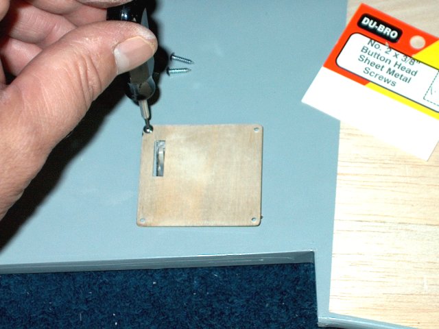
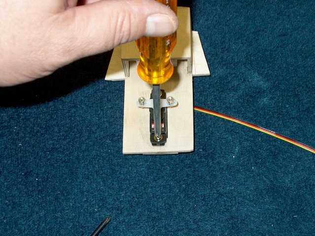
Use four button head #2 x 3/8" screws to
install the servo cover | |
Check for clearance between the cover and
horn. File and sand if necessary | |
Find the Aileron hinges that were supplied
in the kit. Draw center lines down each hinge
| |
Install but do not glue the hinges in the
wing. Note that a third "center" hinge was added in the photo
for extra safety but it is not essential
| |
Install the Aileron on the wing
hinges | |
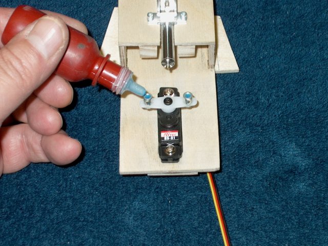
Use thin CA and glue the hinges to the
wing. Clean up with a paper towel and be sure to apply CA to
both sides of the wing at the hinge locations
| |
Install a clevis on one of the pushrods.
Note that plastic clevis' are shown in the pic, but you may
have metal ones | |
Clip the clevis to an Aileron control horn
supplied in the kit. Keeping the wire even with the servo and
side of the cover, position the horn as shown and drill the
hole with a 5/64" bit | |
Install one screw to hold it in place,
then drill the other side and install the second horn
screw | |
Cut and grind the extra screw length from
the top of the wing | |
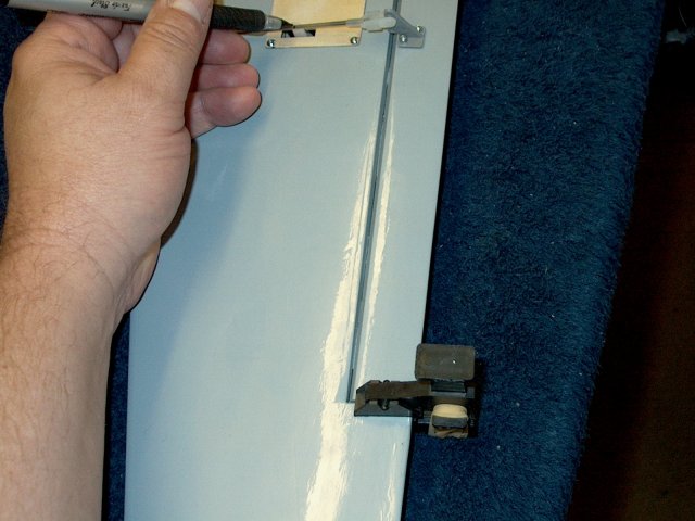
With the clevis installed and the Aileron
clamped (as shown on the bottom) to keep it centered, make
sure the servo is still centered, then mark the location of
the servo horn hole on the rod | |
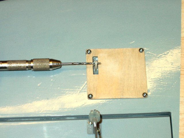
Drill the horn at the end hole so it can
accept the pushrod. Use a 1/16" bit, then open it up more with
a 5/64" bit if needed | |
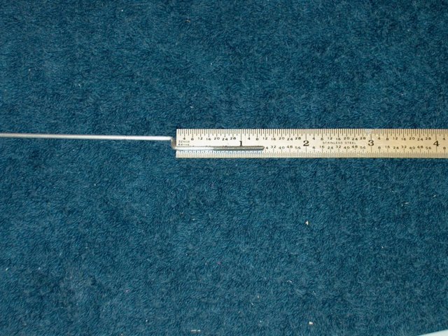
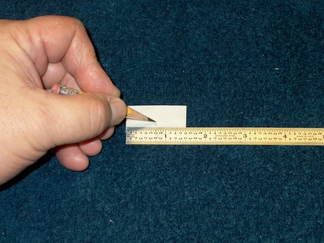
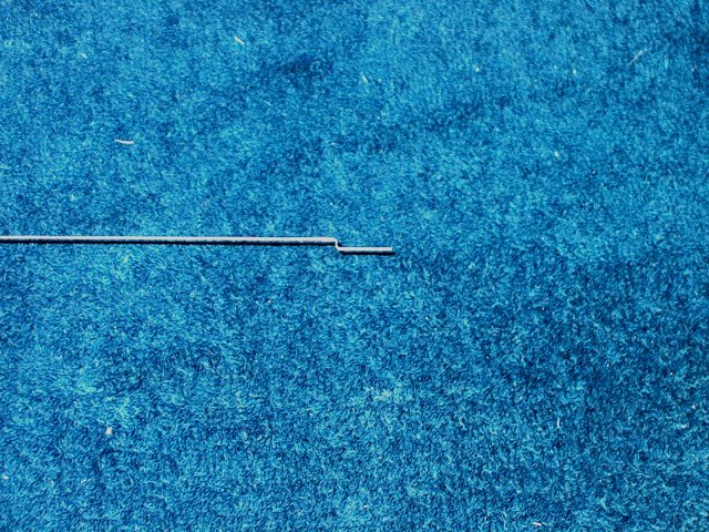
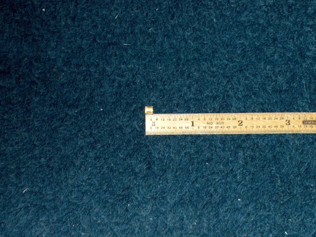
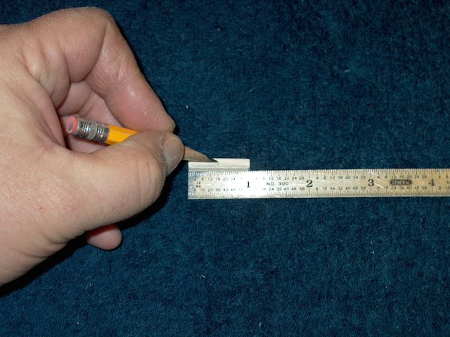
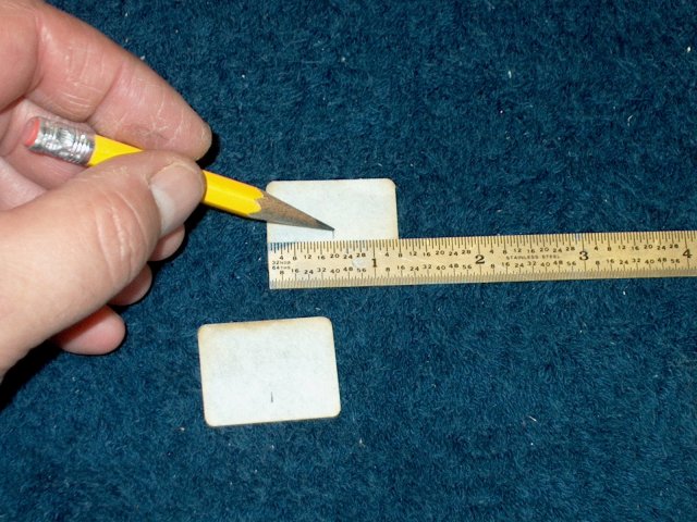
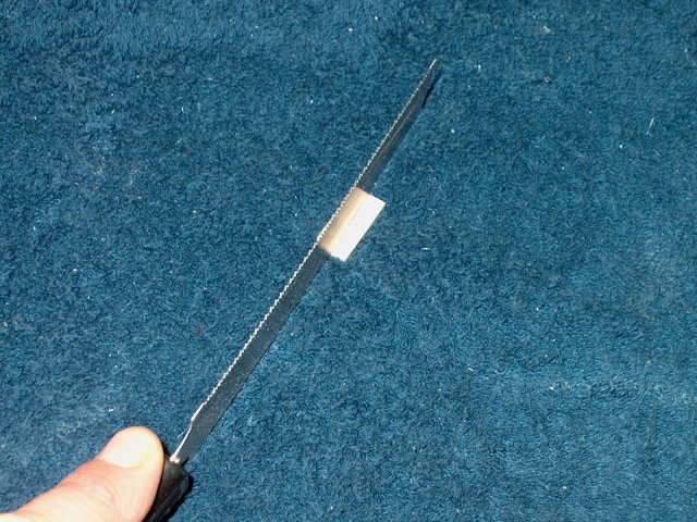
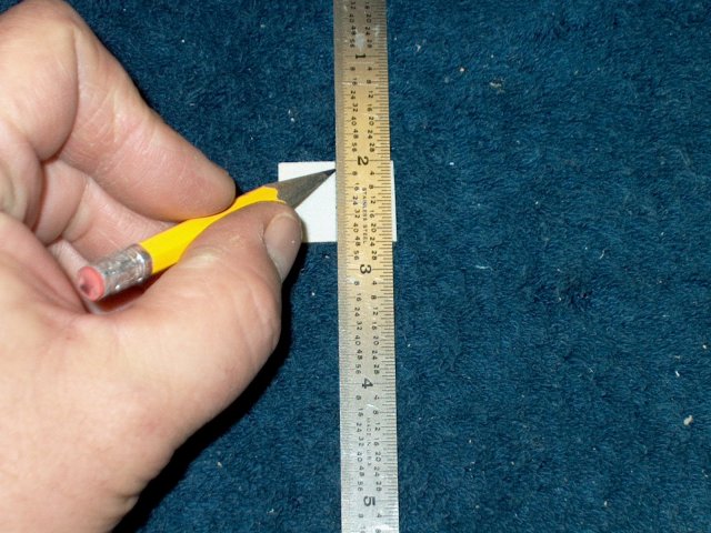
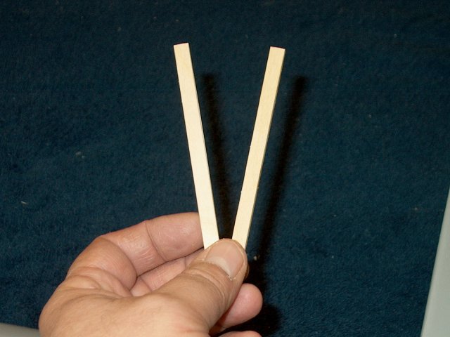
Remove the clevis from the wire and make a
"Z" bend at the mark. A ruler is shown for size
reference | |
Install the clevis on the rod, then
install the pushrod assembly. This concludes the wing retract
and control installation | |
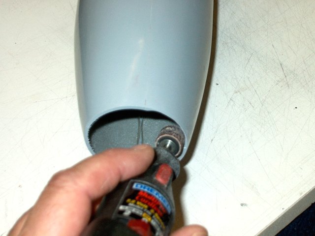
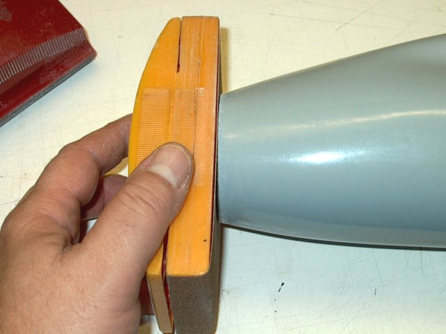
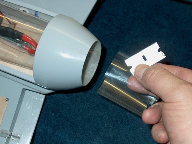
Begin work on the power assembly by
locating a Nacelle, then begin by sanding the lip from the
front of the nacelle. Note that the intake is actually the
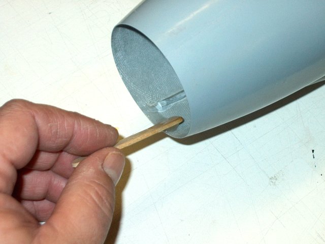
long side | |
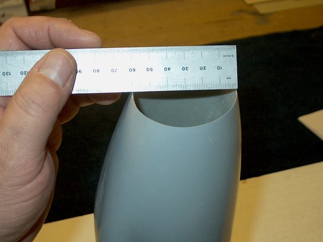
MEasure your intake so you know how much
to sand. You will need toopen it up to about 62mm so the inner
fiberglass intake tube is at 60mm in diameter
| |
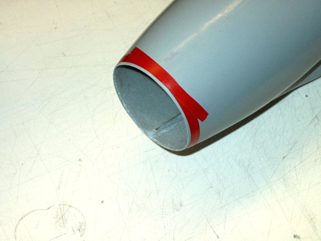
Tape can be used as a guide for sanding.
Wrap some vinyl tape around the end, exposing about 1/8" to
start | |
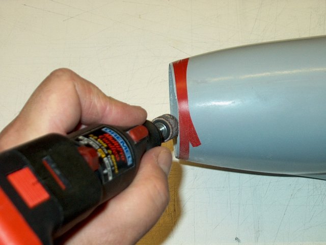
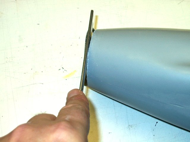
Sand down to the tape. A dremel with a
sanding drum makes it easy work. Be sure to wear a long
sleeved shirt and full length pants, as well as a mask to
prevent irritation that can occur from the dust
| |
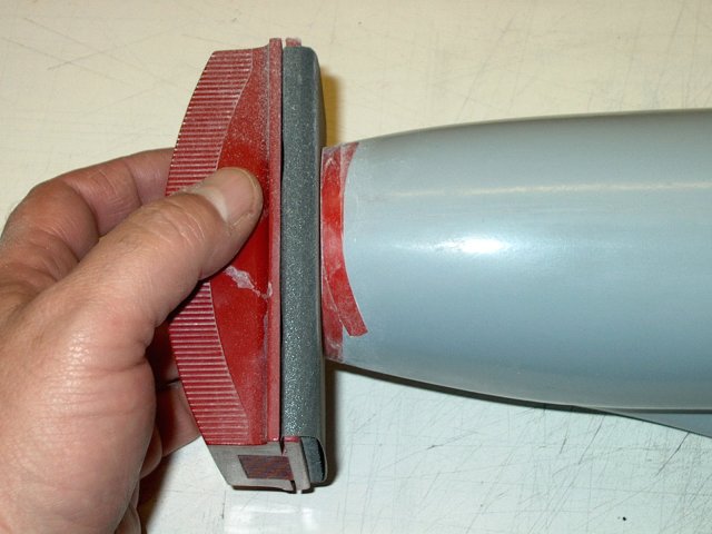
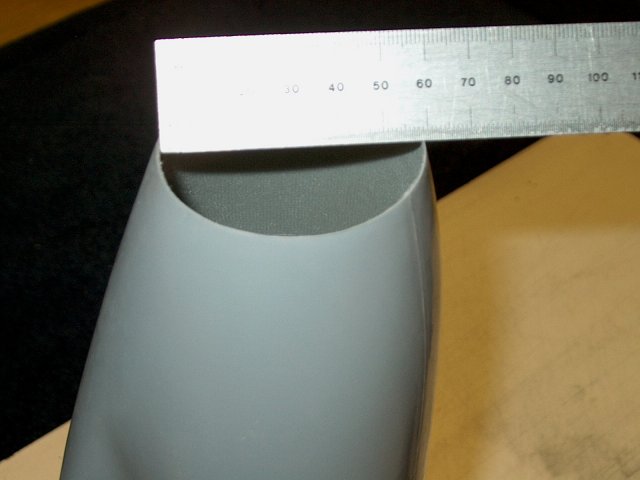
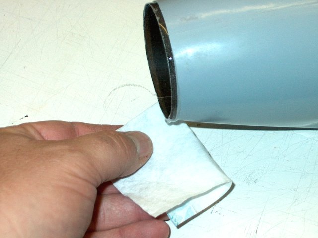
USe a fine sander to finish up the first
cut. Measure the diameter and repeat as necessary until the
hole is opened to the correct diameter
| |
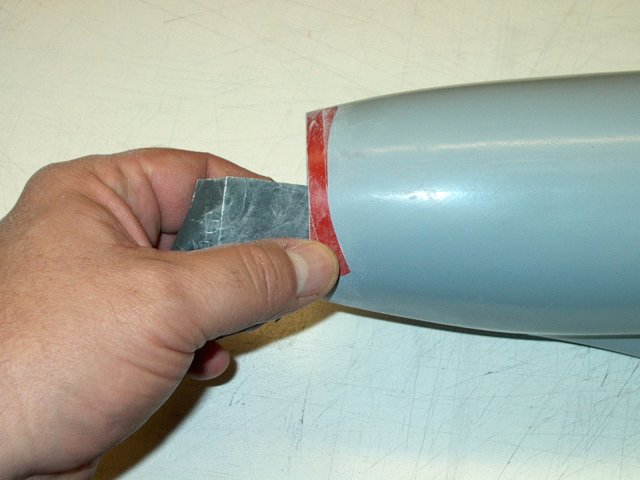
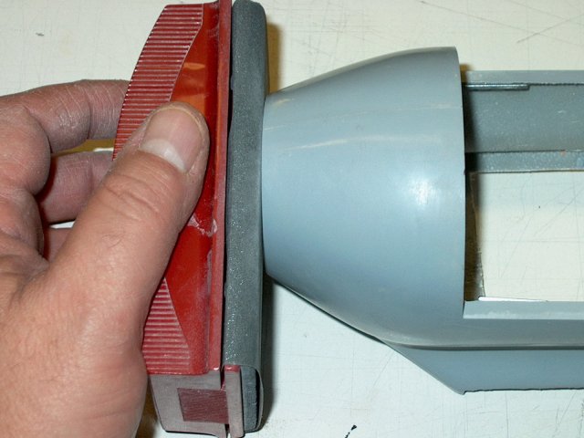
Fine sand the intake lip of the
nacelle | |
Use a drum to sand down the glue seam on
the inside so it is not in the way | |
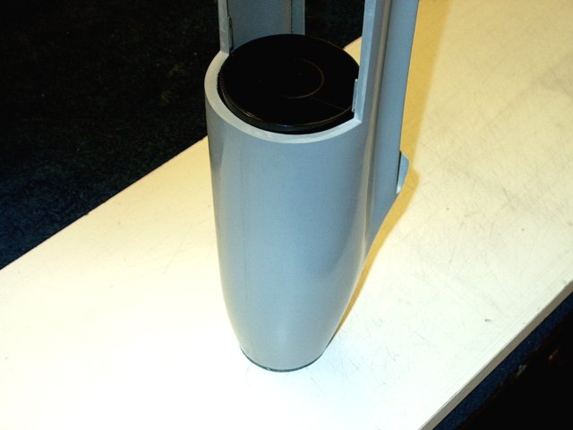
Final measurement shows the nacelle is
ready for the intake inner tube | |
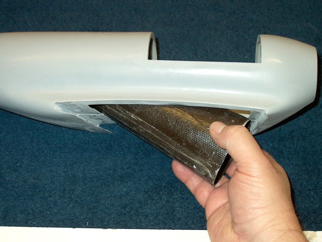
Install the tube from the bottom of the
nacelle | |
Push the nacelle forward through the
intake hole in the nacelle | |
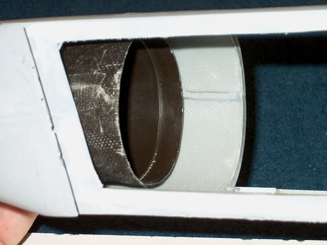
Locate your fan shroud and trim a
monunting tab from one side. Install the shroud in the rear of
the intake and use it to center the intake at the rear
| |

At the front, draw a line around the
Intake Tube | |
USe a dremel or hobby saw to remove the
excess. Be sure to cut the piece long so you have a little
extra to shape it to exact length | |
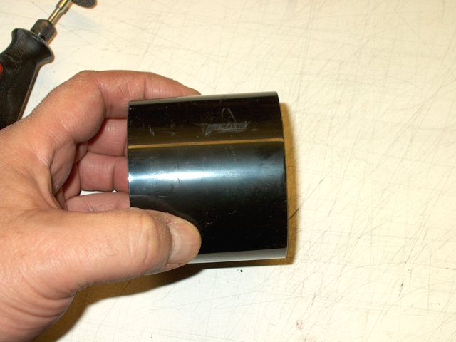
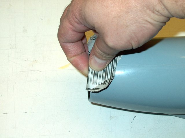
Rough up the outside end of the intake
tube | |
Final Intake Tube length shows around 6
3/4" long | |
Once again, install the intake tube and
Fan Shroud as shown | |
Apply a bead of epoxy around the front
inside of the nacelle as shown | |
Push the fan shroud and intake inner tube
forward through the front until it stops. Remove the excess
epoxy with paper towels and alcohol
| |
Leave the unit upright as shown to alow
the epoxy to flow down into the joint. Also make sure the fan
shroud is seated and centered in the opening
| |
Use a saw or sand the remaining intake
from the front once the glue sets | |
Fine sand the front of the intake
assmebly | |
Lightly sand the edges to slightly round
them as shown | |
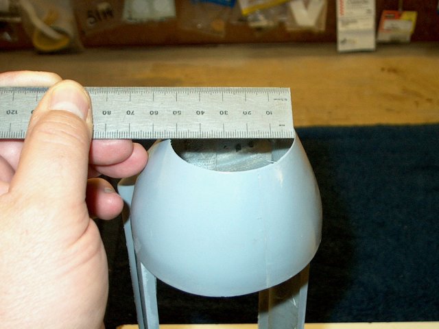
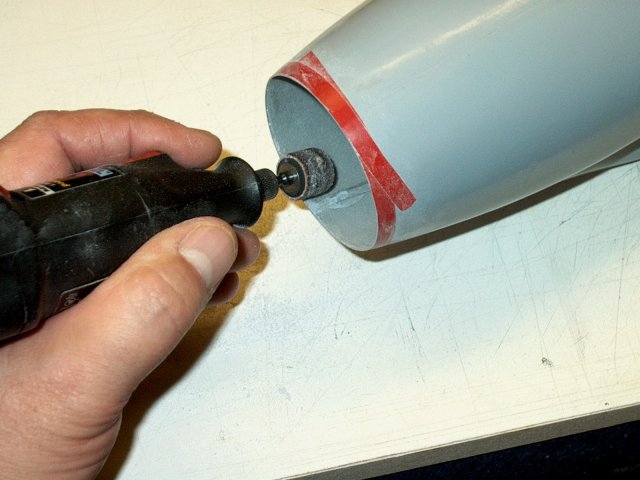
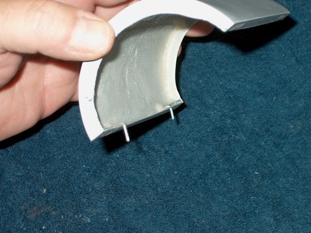
Move to the rear of the Nacelle. It should
be 55-58mm in diameter | |
Sand the opening until it is at the
required size | |
When finished, this model's nacelle was
sized for a 55mm exhaust tube | |
Lightly sand the edges of the Nacelle
smooth with fine sandpaper | |
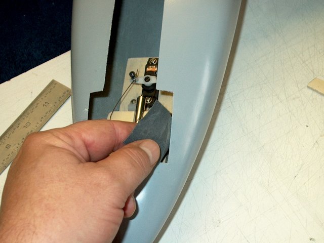
Trim the covering if necessary so that
about 1/16" overlaps on the inside | |
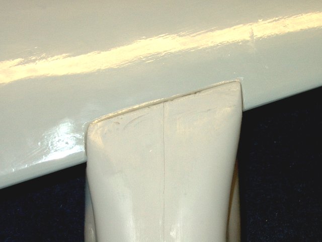
Use a file if necessary to shape the rear
corner of the nacelle on the Aileron side, as the wing may
flatten out at this point. Check the fit
| |
Apply masking tape to each side of the
wing on the outside of each line to catch any epoxy
overflow | |
Apply an ample amount of epoxy to the
nacelle only as shown | |
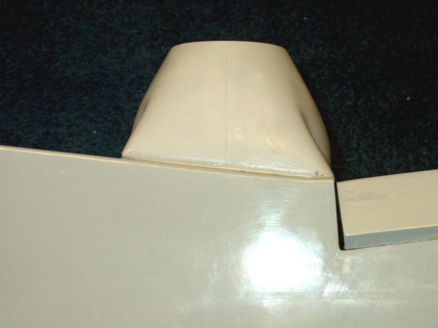
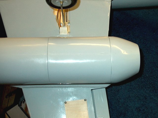
Install the Nacelle on the wing and check
alignment before the epoxy sets | |
If there a gaps between the wing and
nacelle, fill them with a mixture of epoxy and fiberglass mil,
or any other thickener. Remove the tape and clean as necessary
before the glue sets | |
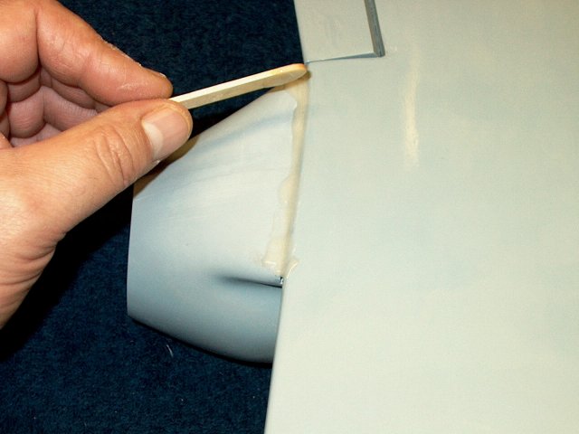
You can apply a small fillet of epoxy
along the rear of the nacelle if desired
| |
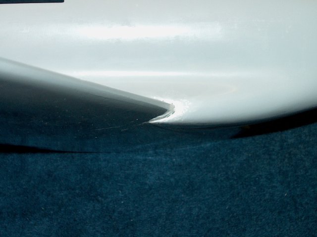
Form the thin fillet to a nice transition
from wing to nacelle | |
A similar fillet can applied to the front
of the nacelle | |
If you are painting your model, fill the
gap at the front of the wing with filler, then sand and
paint | |
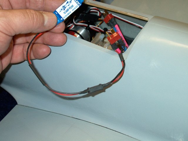
Use a rolled up piece of fine sandpaper to
open the hole for the ESC wires | |
Apply masking to the wing to catch epoxy
spill over | |
Apply masking tape to the fuselage as you
did the wing | |
Use 15-30 minute epoxy to give you some
working time and apply epoxy to the fuselage root slot with a
mixing stick | |
Apply epoxy to the wing spar. Make sure it
is installed in the correct direction with it angling upward
toward the top of the fuselage | |
Spread epoxy along the fuselage wing root
and sides of the spar | |
Apply epoxy the the wing root and spar
slot. Keep the secodary rear spar clean
| |
Install the wing on the fuselage. Make
sure it fits flush, as this will produce a built in dihedral
in the wing. Clean up the excess epoxy and remove the masking
tape | |
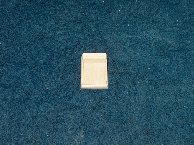
Cut the 1/2" square hardwood block from
the template, then apply epoxy to the secondary spar end and
the inside of the block | |
Install the block in the wing and allow
the epoxy to set | |
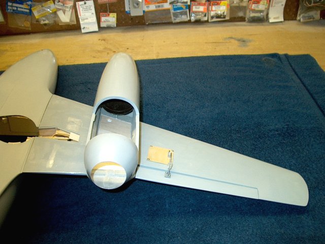
This completes our wing installation.
Repeat the procedure from the beginning for the second
wing | |
Installation of the second wing shown
completed | |
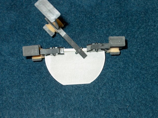
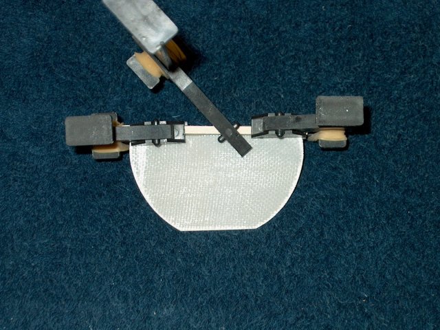
Install the retract units in each
wing | |
Install each strut and wheel into the
retracts | |
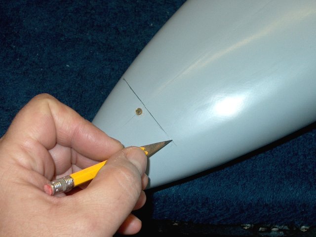
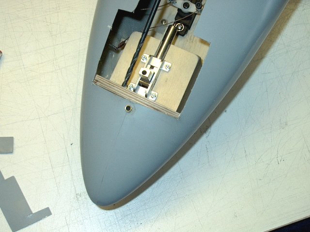
Examine the fuselage and look for the rear
seam of the nosewheel plate that is under the fiberglass. It
should appear as a bump in the fuselage. Draw a line about
1/8" behind the pre-installed gear hole, or far enough away so
you don't cut into the stock former
| |
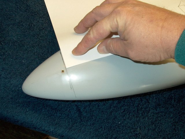
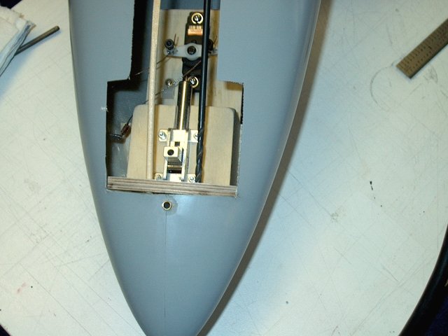
Use a piece of paper aligned at the center
seam to make sure your line is square
| |
Measure 1 1/4" from the center of the seam
in each direction. This will be the location of the sides of
the nosegear hatch | |
Measure and draw lines rearward, making
sure they remain parallel to the center seam. Draw a line at
2" from the front for the rear of the hatch
| |
Draw two lines on the inside 1/2" inward
from the outer lines | |
Measure and draw a line 1/4" from the
front line as shown | |
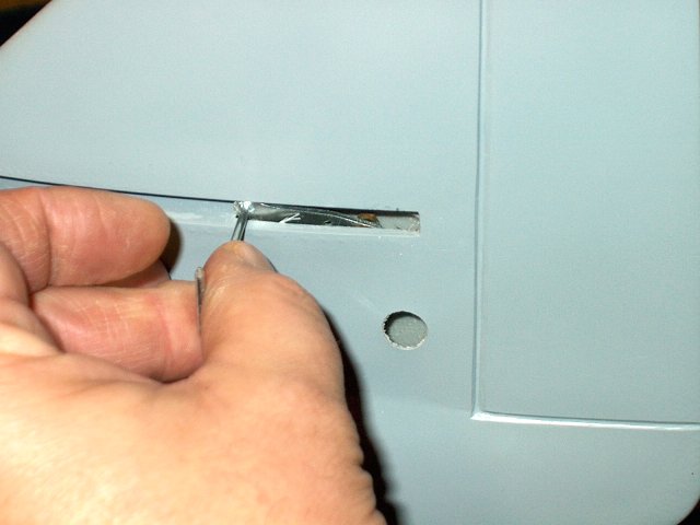
Score and cut the front of the hatch as
shown, taking your time | |
Use a ruler and cut each side outer line
as shown | |
Extend the inner lines rearward on the
fuselage for the main door and back about 6"
| |
Cut the back end as shown. The main door
extends 1/2" into the hatch area. The remaining main door can
be cut to a length of 5 3/4" | |
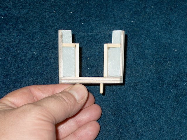
Cut a 1/8" ply Retract Mounting Plate from
the templates | |
Install a 1/8" ply rear plate as well as
two side plates. While the side plates appear longer in the
pics, they should be 1" wide/tall like the rear. Glue two
strips of 3/8" square hardwood block to add more support for
the mounting screws | |
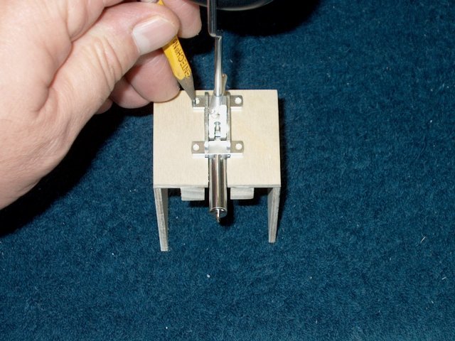
Install the retract and mark the mounting
holes with a pencil, then drill with a small bit
| |
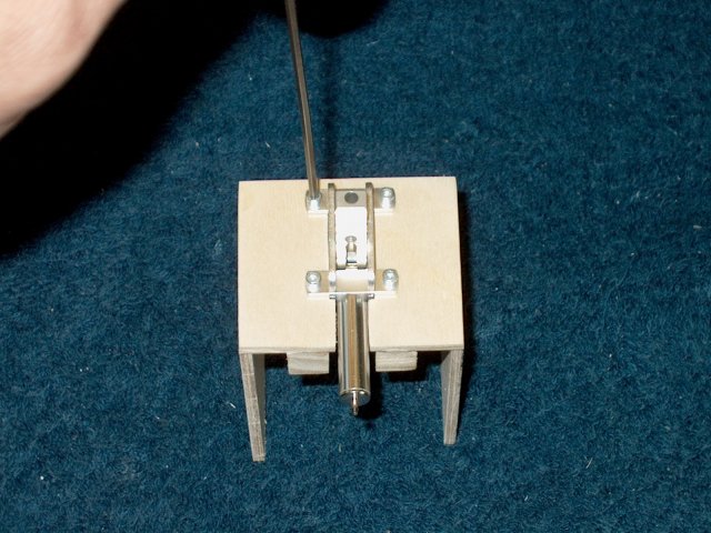
Install #2 x 3/8" long hex head screws to
retain the retract unit | |
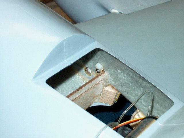
Check the fit of the retract against the
gear plate that came mounted in the fuselage. Additional ply
was added to the back and angled to compensate for the stock
nosegear plate that was mounted crooked
| |
Check your rearward angle on the gear and
sand the back plate as necessary. There should be ample angle
for the rear of the wheel to retract completely, 1/2" or so
past the bottom edge of the fuselage. A cross plate for the
floor is cut from 1/8" ply to fit across the inside of the
fuselage and the retract block sits on this plate. It may take
some time to shape it to fit | |
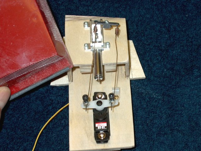
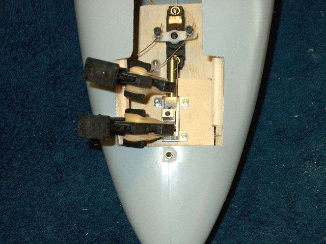
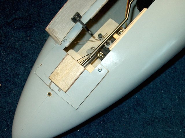
Cut the steering retract servo plate from
the templates. Note that a Hitec HS-81 was used in the
example, so you may need to cut the center hole differently to
fit your servo. Note that the notched sides of the plate
should fit inside the walls of the block
| |
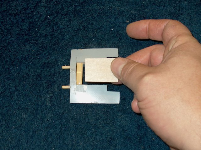
Epoxy the plate to the bottom inside of
the Retract block | |
Apply epoxy to the bottom of the block
assembly. Only apply epoxy in the area as shown
| |
Apply epoxy the the fuselage bottom
plate | |
Glue the two pieces together
| |
A couple of pieces of scrap 1/8" ply can
be cut 3/8" wide by 1" long and glued to the bottom to add
extra grip for the servo mounting screws
| |
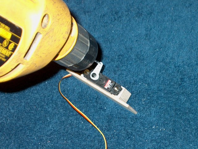
Center your servo using a receiver or
servo tester, then center your horn on the servo and install
the horn screw | |
Install the servo in the plate, making
sure to use the rubber mounting grommets as they will provide
some shock absorbtion for the steering mechanism
| |
Install the mounting screws supplied with
the servo to mount it to the plate | |
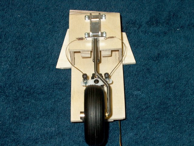
Install two Sullivan #550 pushrod
connectors in the second hole from each end of the horn. Apply
Loktite to the lockdown holes, then install the bolts
| |
Use a tailwheel wiring kit, slide a crimp
over the wire and then run the wire through the end of the
steering arm. Note the arm thin center shaft is on the
bottom | |
Thread the wire per instructions through
the crimp tube | |
Crimp and then trim the excess from the
wire. Repeat the installation for the other side of the
aluminum steering arm | |
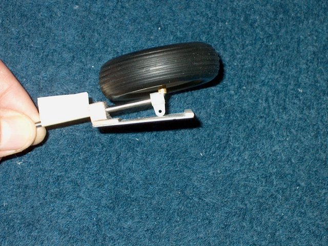
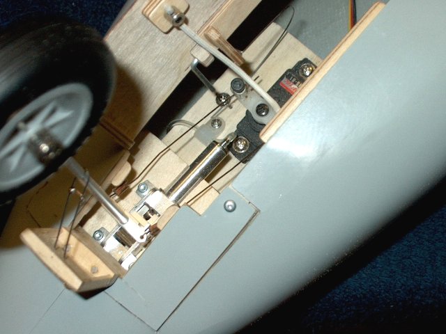
Install the landing gear strut, then run
the wires through the servo connectors. Center, then tighten
the wires with the pushrod connector bolts and trim so there
is about 1/4" wire extending past each connector
| |
Check the functionality that the steering
wires will colapse in the up position, then check that they
are not too tight to lock down. If the gear doesn't lock down,
your wires are too tight. They should be taught, but not
tight. Adjust if necessary | |
Sand to round the corners of the block so
the wires do not snag on them during operation
| |
Instsall a 3/32" aileron horn bracket as
shown to help with the air hose routing
| |
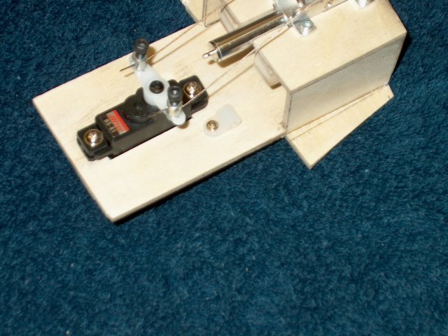
Apply epoxy to the back plate and bottom
edges of the cross plate | |
Install the retract assembly against the
bottom floor and rear stock gear plate. Make sure the gear is
centered and not angled left or right
| |
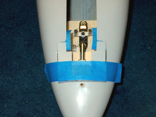
Cover the block with masking, then apply
an epoxy/glass mil mix along the edges of the cross plate as
shown | |
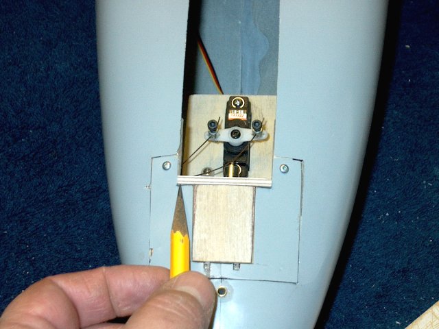
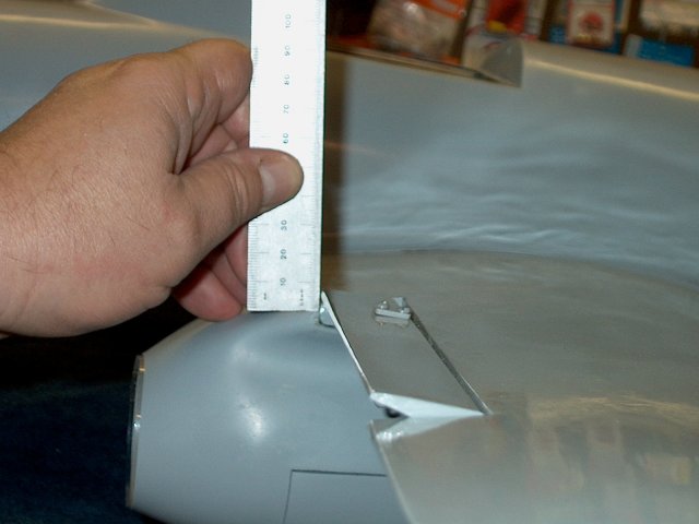
The servo plate should be receeded into
the fuselage at least 3/4" | |
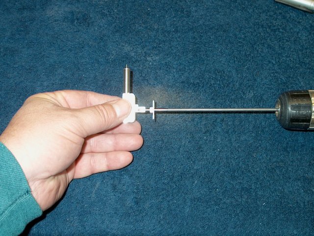
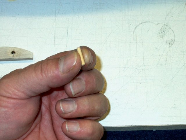
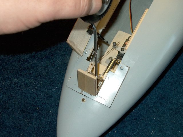
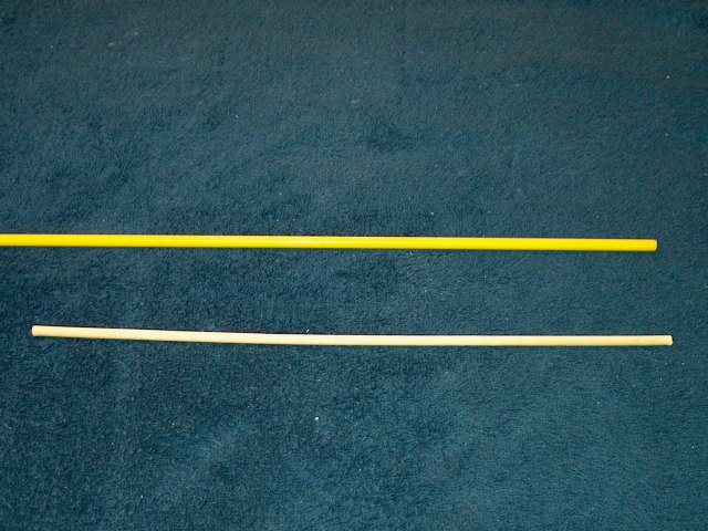
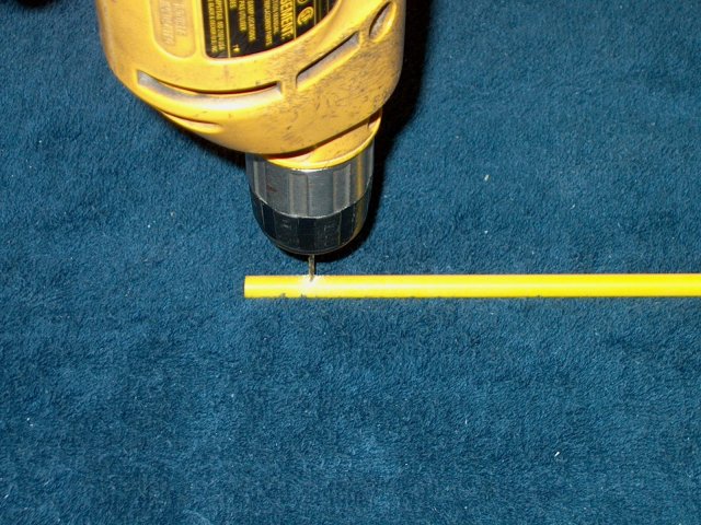
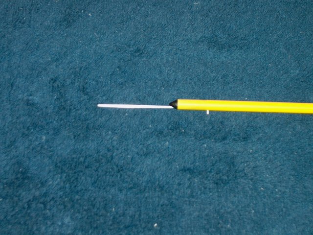
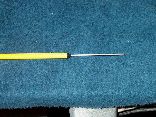
A custom length of 1/8" strut wire was
used to make the extra long nosegear strut. A drill and dremel
were used to cut down the 1/8" wire diameter to 3mm so it
would fit the retract. Narrow about 1" of wire from the
end | |
Insure the retract and steering arm can
fit the wire without being too loose or binding
| |
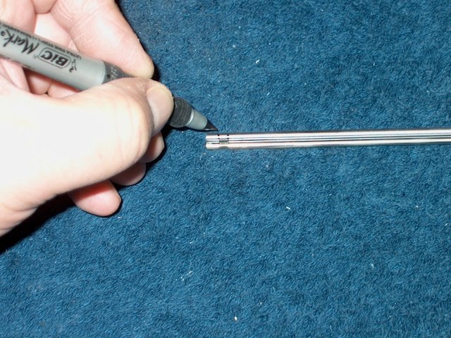
Use the stock retract wire to mark the
notch location | |
make sure the mark is drawn completely
around the wire | |
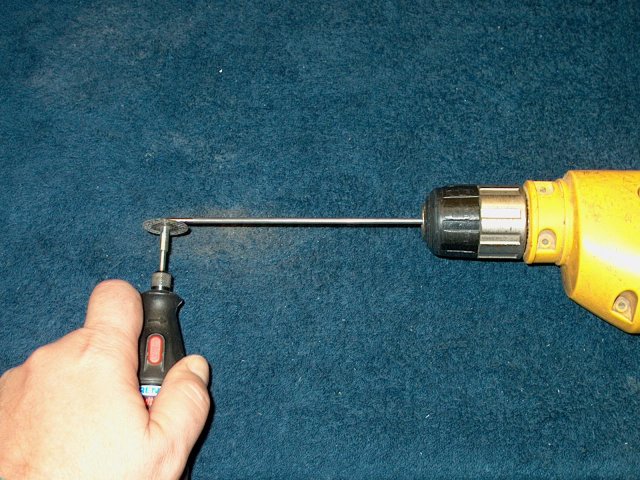
Use a dremel with cutting wheel to notch
the wire while spinning it in a drill. Use a file and
sandpaper to smooth the notch, using the drill to spin it like
a lathe. Check the assembly in the retract
| |
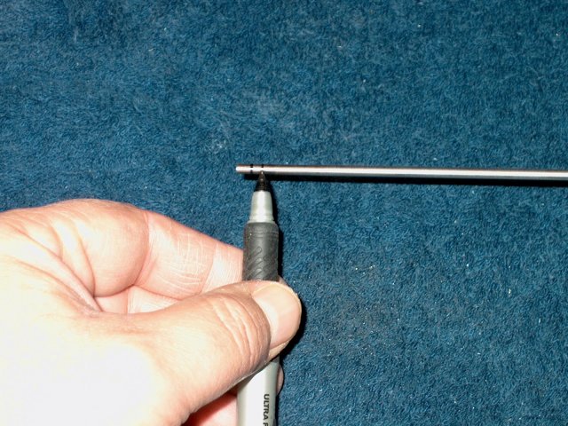
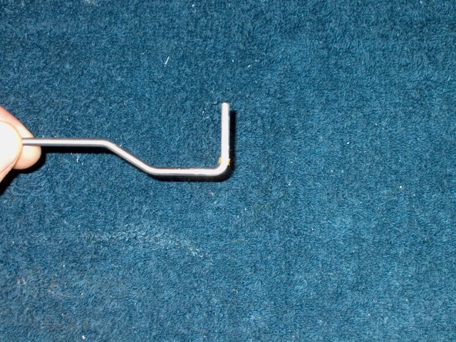
Make a mark at 1" from the other end of
the gear, then bend a right angle. A vise was used, but you
need to grind a slight round edge on the vise before hammering
the bend, otherwise the wire will crack from bending against a
sharp surface | |
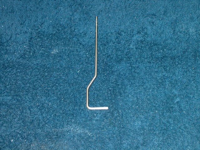
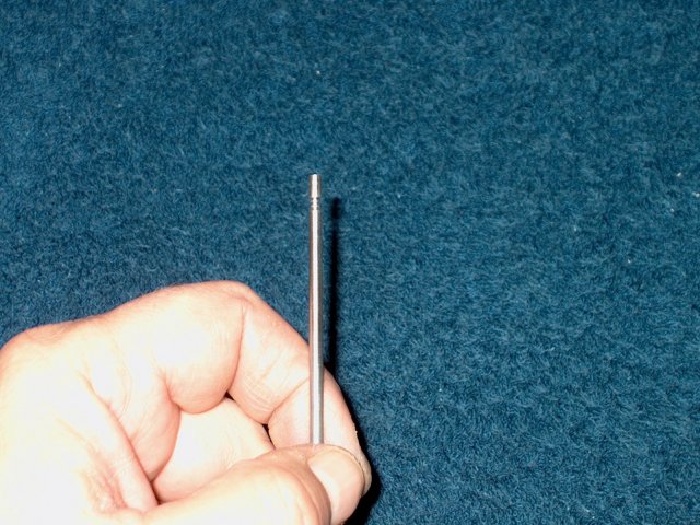
Shape the gear to the template
| |
Slide a 1/8" id brass sleeve over the end
of the strut | |
Install the wheel, then the collar. Make
sure the wheel spins freely and doesn't bind
| |
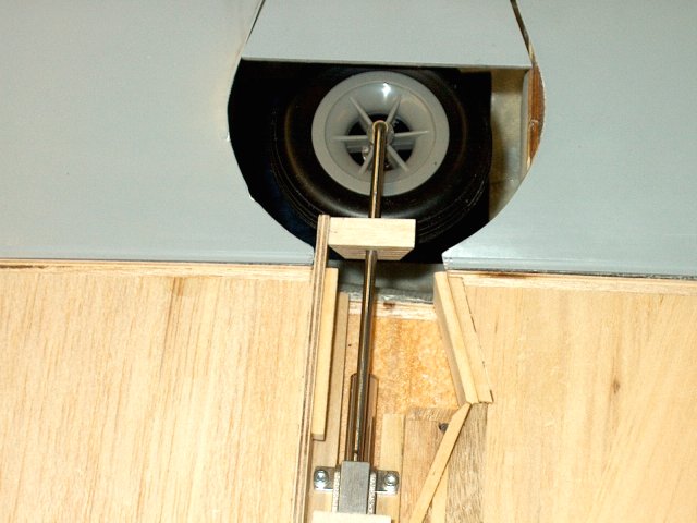
Install the strut in the retract. Check
for rotation/turning without binding while the retension screw
holds the strut in place | |
Colapse the retract. It should clear the
rear of the main door | |
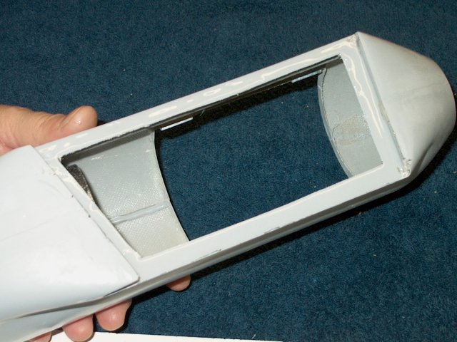
Use a sanding drum to remove the glue seam
left from manufacturing | |
Lightly sand the edges of the opening
smooth with fine sandpaper | |
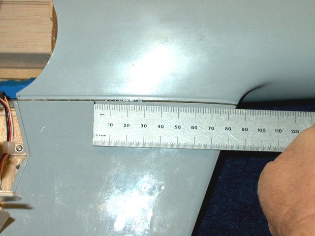
Position and trace the nose opening curve
to a piece of 1/8" or 1/4" ply as shown
| |
The ply piece must be 1/4" thick. If you
used 1/8" ply as in the photos, make another piece
| |
Laminate the two 1/8" pieces together with
epoxy | |
Check the fit and adjust as
necessary | |
Use a 1/8" drill and drill a hole as
shown, through the 1/4" ply and into the stock ply former in
the nose | |
Use a wood dowel to hold the drilled
section in place and drill a second hole
| |
Cut two pieces of 1/8" dowel to a length
of 1/2", round the tips, then epoxy them in the holes
| |
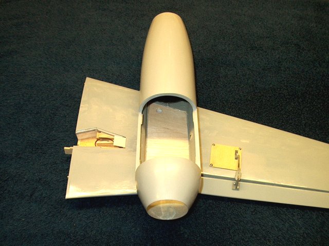
Insert the ply plate and dowels into the
front of the nose. Use a piece of sotch tape between the joint
to catch glue overspill. Apply epoxy to the ply top and glue
both halves of the fiberglass hatch to the wood. Use tape to
hold it in shape until the glue sets
| |
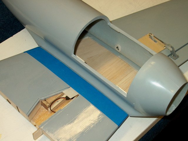
Use a scrap piece of 1/8" ply to begin
framing in the opening | |
Put a piece of 1/4 angle balsa across the
back, then sand to shape | |
Apply epoxy to the 1/8" ply edge and angle
stock, then epoxy in place | |
Frame in the edges of the hatch with 1/8"
square ply as shown | |
Build and glue a second frame piece for
the opposite side of the fuselage. glue, then clamp in
place | |
Use smal 1/8" square pieces of basswood to
finish framing the inside of the hatch as shown
| |
Disgard the fiberglass pieces of small
door you had and cut one from 1/32" ply. Cut, sand and shape a
piece of 1/4" thick hardwood for the rear
| |
Frame in the inside of the door with 1/8"
x 1/16" pieces of basswood on the sides and 1/8" ply on the
front. Be sure to keep the curve in the door
| |
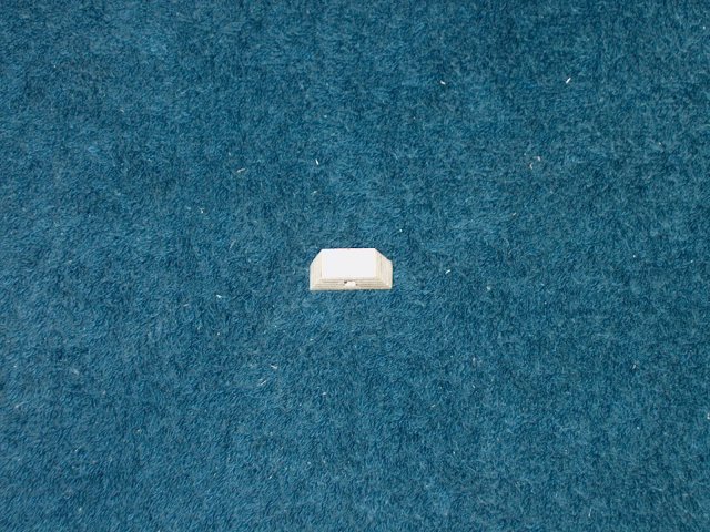
Cut to shorten the door stop tabs as
shown | |
Set the door in the opening and tape in
place. Small Robart pin hinges are used for door
mounting | |
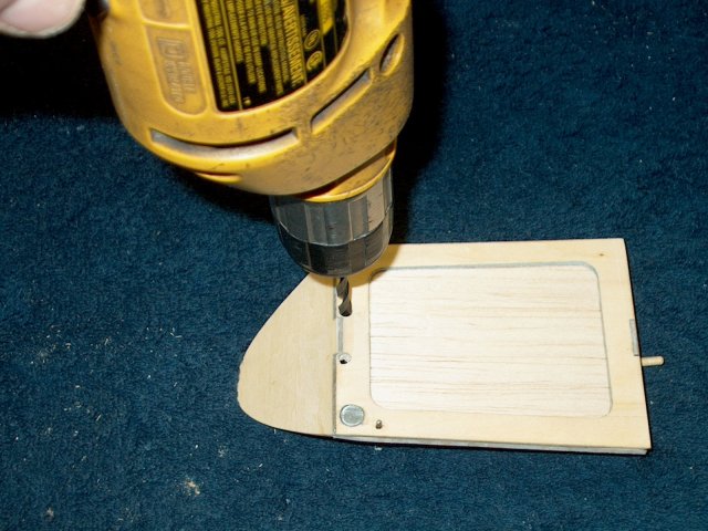
Use a drill and make two holes into the
door for the hinges | |
As the hinges need to recess 1/8" inside
the top panel, cut 1/8" square openings for them. Drill
downward from this position so the pin hinges use the body of
the door plate as a good anchor to bond
| |
Check the fit of the hinges and clean up
the holes | |
Apply epoxy through the holes in the
hatch | |
Install the hinges in the hatch and dry
fit them to the door. Check for alignment and ease of movement
befor the glue sets | |
Trim the protruding hinges flush with the
hatch as shown | |
Use a toothpick to apply epoxy to the
holes in the small door | |
Install the door
| |
Position the door and check for free
movement before the epoxy sets | |
Trim the hinges flush as shown
| |
Cut two hatch mounts from the templates to
shape | |
Epoxy one of the mount plates in
place | |
Epoxy the other mount plate in the
fuselage | |
Install the hatch, then make marks at the
center of each end | |
Use a small drill to drill holes through
the hatch and the ply hatch mounts. Use #2 button head screws
to retain the hatch | |
Cut a piece of 1/16" x 3/8" wide ply to a
length so it fits inside the small door. Use a saw as shown to
cut only halfway through, so the surface is slotted
| |
Use sone .020" wire to make the shape as
shown. Cut two slots for the "L" shapes to fit
| |
Epoxy a piece of scrap 1/32" ply to hold
the wires in the slots | |
Bend the wire at an angle as shown
| |
Apply epoxy to the bottom of the
mount | |
Epoxy the wire and mount into the end of
the door as shown | |
Twist a piece of solid copper wire around
the loop as shown, with the twists on the away side of the
loop | |
Solder the wire in place. the wire will be
used by the strut to "open" the door
| |
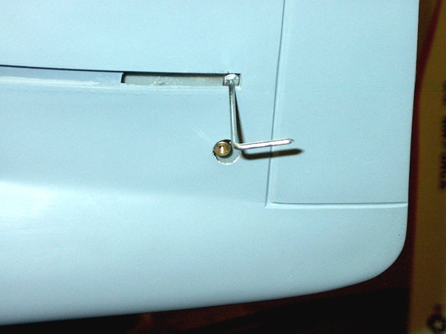
Install the strut and check the motion of
the door. The wire loop can be bet up or down to adjust so the
door just closes at full retraction
| |
Check opening of the door; it should not
bind when the retract is in full down position
| |
Cut a piece of 1/8" ply to fit the width
of the large door opening | |
Shape the ply piece to match the curve of
the hatch/small door | |
Cut two pieces of 1/64" ply so they are
oversized on all sides by about 1/4"
| |
Tape the door opening to catch epoxy
spillover and tape one end of the two ply pieces
| |
Open the pieces like a book, then apply a
film of epoxy to both pieces. Fold them together and press out
as much epoxy as you can | |
Tape the door to the opening, overlapping
the sides and rear. Slightly overlap the front at the
hatch/small door. Allow the epoxy to set halfway (5-10 mins
for 5 min epoxy) | |
Teh door can be bent and shaped while
still curing and semi soft. Trim the sides and back end so it
fits the opening. Flex or shape it as necessary. It should
have a slight curve at the front, as well as a slope
| |
Cut the outer door hinge mounts from 1/8"
ply and 1/32" ply | |

Slot the two ends of the ply, 3/32"
outward from the corners so a piece of small pushrod can fit
the slot | |
Laminate the two pieces together with
epoxy, then run the rod through the slots before the epoxy
cures to clean out the holes | |
Make two door inner hinges from plywood.
On the left is a 1/32" ply cap piece that is epoxied to cover
the slotted piece on the right. The right piece has a 1/32"
base piece, a 1/16" x 1/16" end edge piece on the far side and
a 1/32" x 1/4" wide piece on the left. Assemble the
hinge | |
Glue the hinge in place on the outside
edge of the door as shown, with the thin spacer closest to the
edge. Cap the assembly and clean up any excess glue. Make sure
the slot is clean all the way through
| |
The door is slotted just over 1/8" so the
Outer Hinge clears | |
Door assembly connected to the Outer
Hinge | |
Make a hinge pin from 2-56 pushrod so it
extends completely through and past the other end by at least
1/8" | |
Apply epoxy to the Outer Hinge and install
in the fuselage | |
Clamp the assembly down and make sure the
hinge is flush with the edge of the fuselage
| |
Install the door with the pin from the
front. You may have to flex the door until it clears the
opening. Note how wide the front outer hinge is...there is a
3/4" long piece of 1/8" wide Carbon Fiber rod under the narrow
hinge to help support it and prevent breakage
| |
Make a 1/8" x 1/8" horn from ply using
1/16" ply to elevate the bottom | |
Epoxy the ply horn in place as
shown | |
Bend a small piece of fine music wire to
the shape below | |
Install the wire through the ply horn,
then curved down and use a screw to hold it in place. The door
should now be able to "spring" open and closed. Squeeze the
bend closer if the tension is too much, as the door should
snap shut without a hard slam | |
Round a piece of 3/8" square hardwood 1/2"
long is off at the top into a half-moon shape. A 3/32" hole is
drilled through the center | |
Epoxy the piece to the frame under the
outer side as shown. Note the position
| |
Tie a knot in one end of a piece of heavy
round elastic cord, then run it through the hole as
shown | |
Make a wood block from 1/8" ply with a
1/32" top cover. Drill a 3/16" hole in the center of the 1/8"
square and drill a 1/16" hole in the center of the 1/32"
square. Install the Sullivan #550 connector through the small
hole, install the nut and glue the two pieces together. Glue
the assembly in position as shown in the pic. Note the
position of the elastic cord | |
Adjust the length of the cord until the
door closes completely and has little or no slack inside, then
lock it down with a set screw. Turn the model carefully
upright and if adjusted properly, the gear should fall out of
the door under its own weight and lock down. Adjust as
necessary the door tension and cord position. This completes
the retract unit assmebly for the nosegear
| |
The supplied wood dowel used for the
Elevator pushrod was warped, so a fiberglass pushrod was
subtituted. Cut the rod to 15 1/2" long
| |
Drill one end of the rodper instructions
supplied with the glass pushrod | |
Install a 2-56 pushrod with a right angle
bend through the pushrod cap and outward, then epoxy the black
cap in the pushrod | |
Repeat for the other end and install the
2-56 pushrod | |
Bend a right angle at 1" from the end of
one side, then install the clip as shown
| |
Center the rear of the Stab in the tail,
then mark each side | |
Adjust the front of the stab until both
sides are equally spaced | |
Draw the location of the stab
| |
Us a razor to cut and remove the covering
just inside the vertical stab location. Remove covering from
both the top and bottom of the stab
| |
Use an iron to seal the seam where your
cuts were made | |
Clean out the rear inside of the stab so
it doesn't bind on the Elevator pushrod
| |
Slightly round the center of the Elevator
control assembly with a dremel so it will not snag inside the
vertical stab | |
Make a bend as shown in the center horn
and install the pushrod connector. Test fit the assembly and
make sure it is centered when installed in the vertical stab.
If not, make the bend shallower until there is no rubbing and
the rods appear centered | |
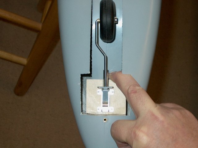
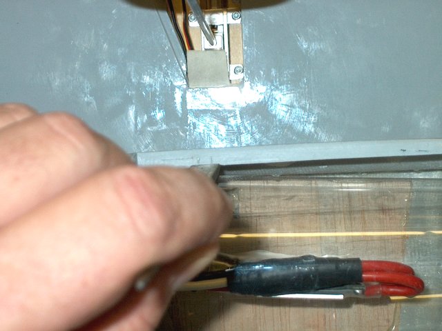
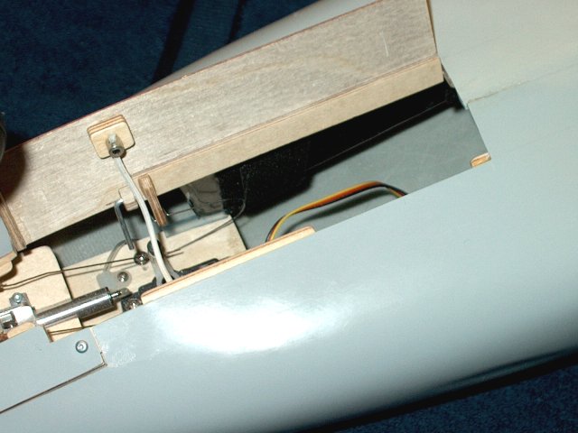
Install the Elevator control assembly into
the fuselage as shown | |
Rotate the control rods so the horn is
visible in the large hole below the slot
| |
Measure and make marks on the rod at the
stab so the assembly can be evenly centered during permanent
installation | |
Install and center the stab on the marks
you made. Clean up the marks, then use thin CA on the top and
bottom seams to glue the stab to the fuselage. Believe it or
not, thin CA works great here | |
Use an iron to seal the seams on each
elevator. Slice the end down the center where the metal rod
will install, then use the iron to make a divot for the
rod | |
Draw a center line down each of the four
hinges | |
Install the hinges in place up to the
center lines | |
Apply epoxy to each elevator rod hole with
a toothpick | |
Quickly install the elevator over the
control rod and hinges. Clean up excess epoxy, then check
movement and centering of hinges and apply thin CA to the top
and bottom of each hinge to secure in place
| |
You should be able to find the elevator
pushrod connector through the hole. Install the pushrod and
clamp it down in the connector. I substituted a 3mm set screw
for the bolt that was supplied | |
Make an Elevator servo plate from scrap
1/8" ply and 3/8" square hardwood stick
| |
Trim away one side of the servo arm, then
use a receiver or servo tester to center your servo and
install the arm as shown | |
Install the servo on the board with servo
tape, then fit and epoxy the two hardwood blocks on the sides
of the servo | |
Install servo mounting hardware, grommets
and finally mounting screws to secure it in place
| |
Drill out the end hole in the arm so the
2-56 rod will fit | |
Center the servo once again before final
installation | |
Rough up the area for the servo plate
inside the bottom rear of the fuselage
| |
Apply epoxy to the bottom of the plate and
glue in place, making sure the servo arm is located near the
pushrod | |
Clamp the elevators even with the
horizontal stab, then install the pushrod on the servo arm,
loosen the rear set screw and adjust as needed
| |
Finish installing the air hose for the
retracts | |
A clamp is made for the forward
hose | |
Install the hose clamp as shown for the
front wheel assembly | |
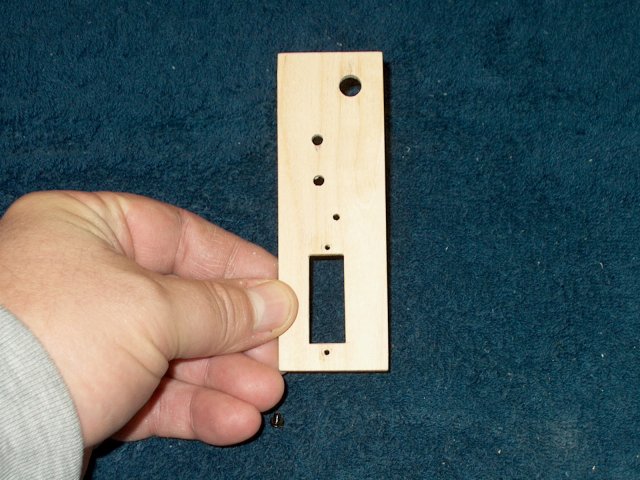
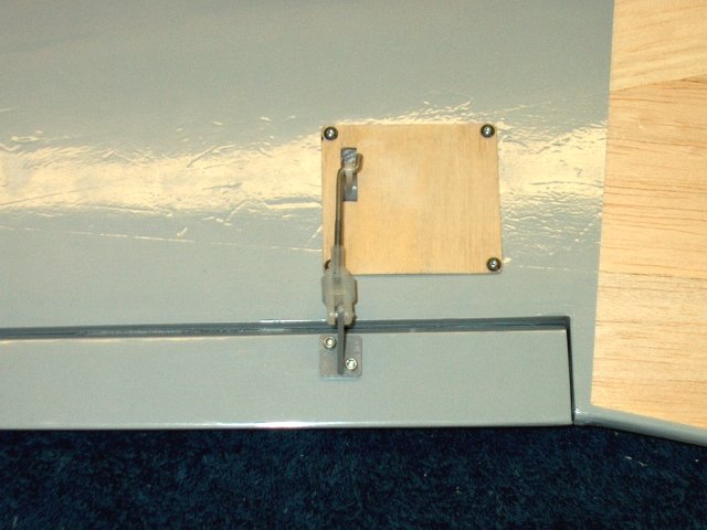
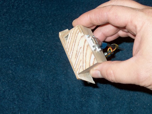
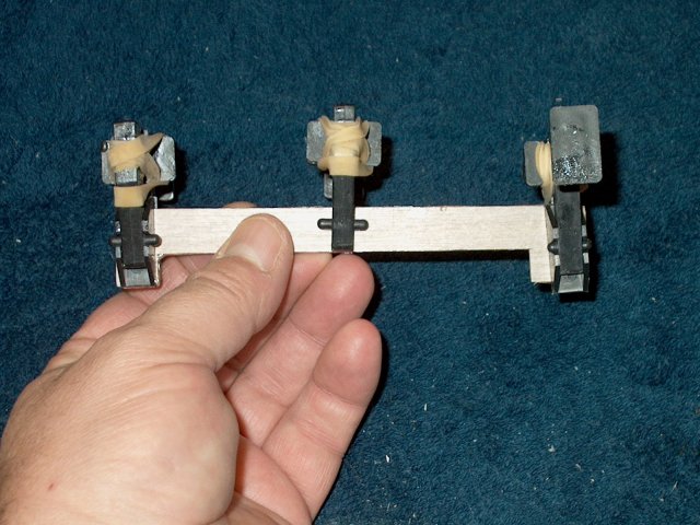
A 1/8" ply Retract Control Panel is built
from the templates | |
Install all parts on the panel
| |
The panel should appear as shown. The
bottom stick is made from 3/8" hardwood and 4-40 blind nuts
are installed to mount the panel in he fudelage
| |
Rear view of panel
| |
Install the hardwood stick in place as
shown with epoxy, then cut small wedges and epoxy them in the
corners for support | |
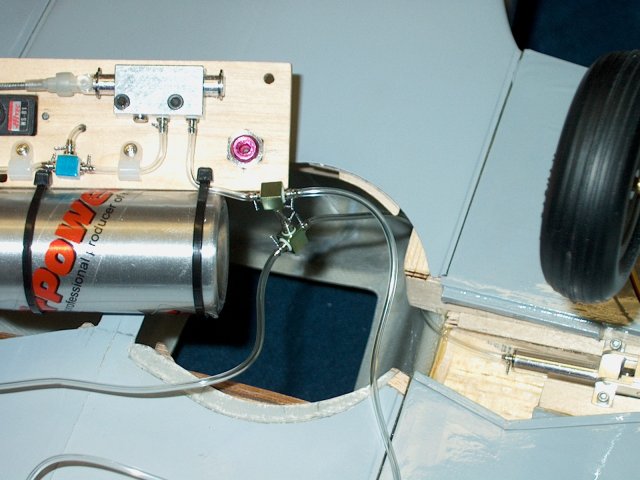
Connect the hoses to the supplied "T"
fittings supplied in the retract kit
| |
The Retract Control Panel can be mounted
in place with two 4-40 x 1" bolts as shown
| |
Install the air hose in the front retract
assembly | |
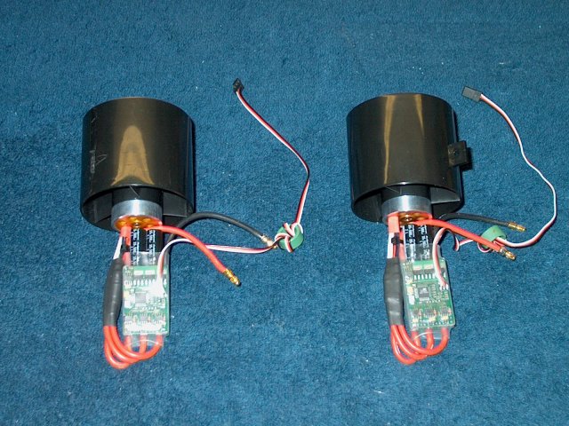
Build your fan units following the
instructions supplied witht he fans, or go to
www.warbirds-rc.com in the "Research Center" for step-by step
instructions on assembling the most common fan
assmeblies | |
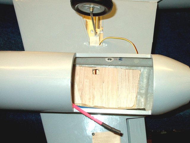
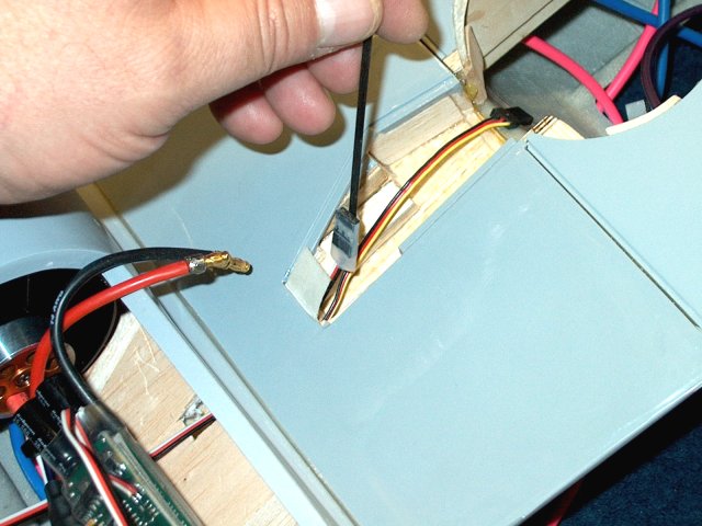
Elongate the opening for the power wires
to make it easier to run | |
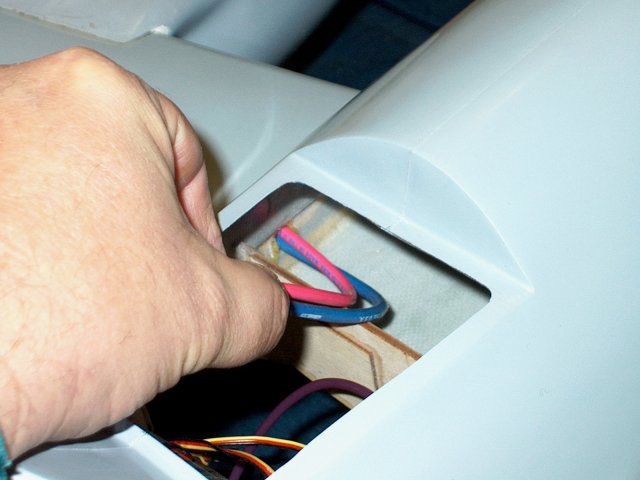
Install the power wires from the inside of
the fuselage | |
Pull them out of the hole in the wing as
shown | |
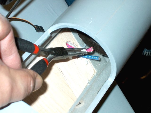
Solder the connectors for your ESC to the
wires | |
Cut a 1/2" square opening along the
aileron servo wire run as shown. Be careful to only cut
through the balsa and not the servo wire
| |
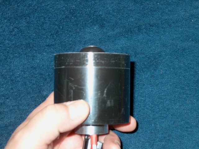
Use some layers of tape to build up the
front end of each fan for a tight fit into the intake
tube | |
Check the fit of the fan in the
intake | |
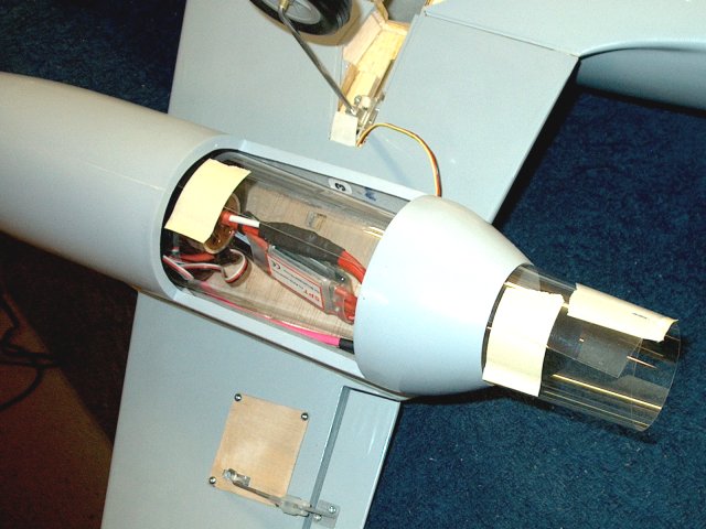
Install the exhaust ducting and tape in
place once fitted to the fan and exit hole
| |
Use clear packing tape and a burnishing
tool to finish the exhaust tube | |
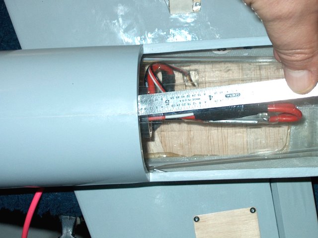
Make a mark on the thrust tube for the ESC
wires | |
Use two washers to sandwich the duct and
cut out the hole for the wires | |
Use a flat piece of carbon fiber or a
small wire and run it from the retract area where the aileron
servo wire exits through the hole you cut earlier
| |
Tape the ESC radio wires to the rod and
carefully pull it through the hole | |
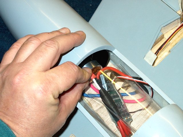
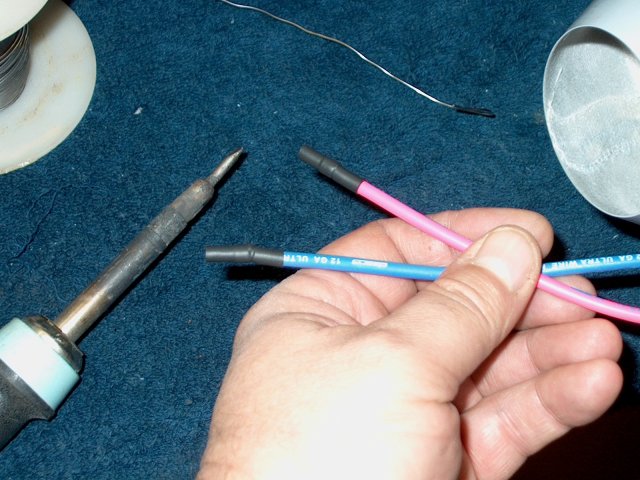
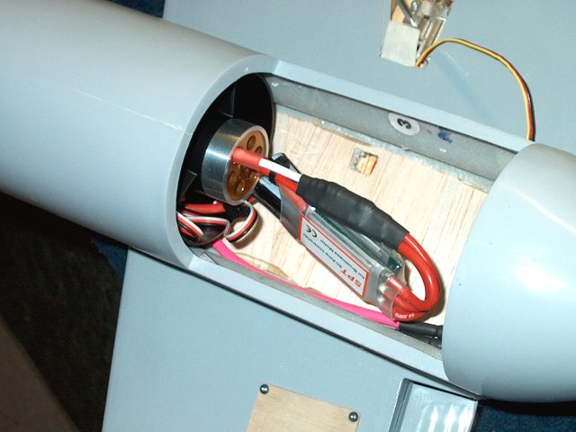
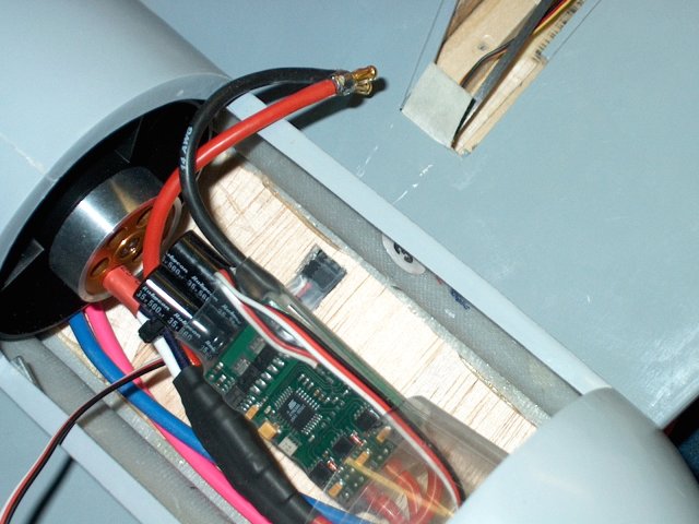
Run the power wires and ESC servo wires
through the hole in the exhaust tube. Install the power wires
on the ESC and use heatshrink to hold them
| |
Slide the exhaust tube over the rear of
the fan | |
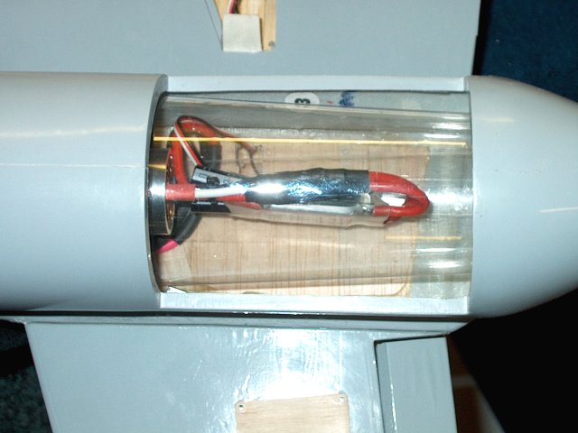
Install heavy clear packing tape to fasten
the tube to the fan | |
Use a razor to remove the excess exhaust
tube from the rear | |
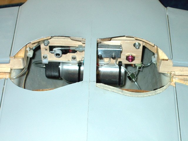
Install four "L" shaped wires in the botom
of each motor hatch as shown | |
Some light sanding on the nacelle may be
necessary for the wires to clear. The wires are bet slightly
outward as a safety catch in case the magnetic retension
fails | |
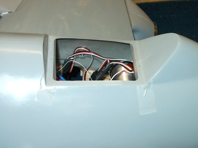
Cover is installed in the motor
opening | |
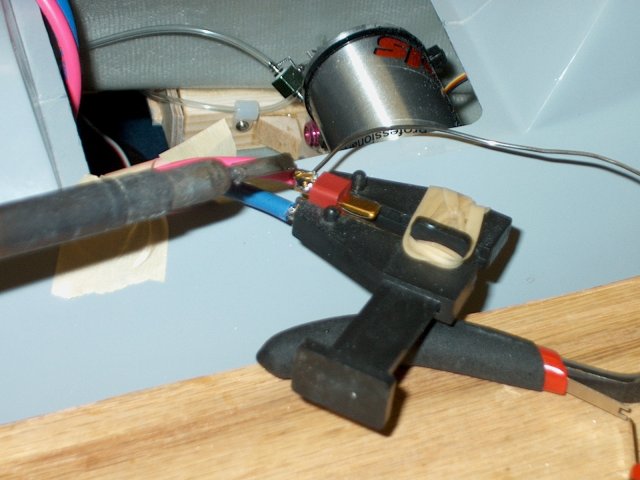
Solder Deans connectors tot he power wires
in the fuselage. Two batteries are used, one for each motor
assembly. | |
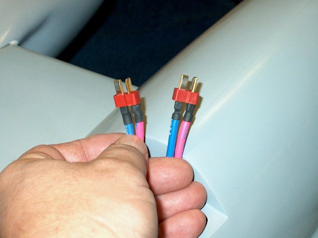
Add the heatshrink to the wires to protect
the Deans Ultra Conmectors | |
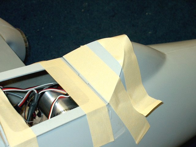
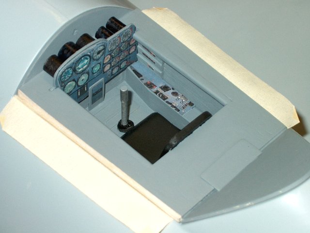
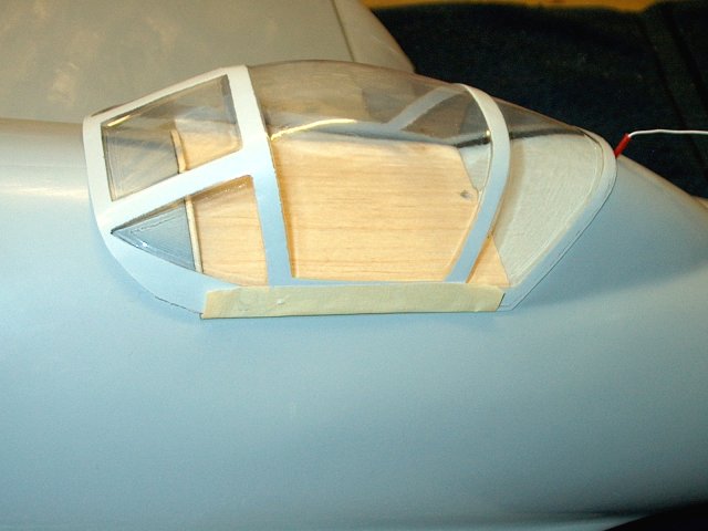
Cover the front and rear cockpit area with
plastic | |
Install the cockpit floor and tape it in
place so it is centered, then epoxy the rear plate supplied in
the kit to the cockpit floor. Tape in place until the glue
dries | |
Epoxy the front plate in place. A clamp is
used to hold it while the epoxy sets
| |
Remove the cockpit assembly and sand the
bottom to a smooth finish | |
Cut two pieces of 1/8" thick ply about
1/4" wide and the length of the cockpit. The will be used as
stiffeners along the outer sides of the fuselage cockpit area
to remove bowing in the fiberglass. Epoxy the sticks in place
under each side lip | |
Install the cockpit and tape in place,
then drill a 1/8" center hole as shown in the front cockpit
plate | |
Epoxy the supplied wooden dowel in place
and check for fit | |
Install the cockpit, then tape it centered
in place and use a sanding block to shape the rear ply.
Masking tape in installed on the fuselage to prevent
scratching of the surface from the sandpaper
| |
Drill two holes in the corners for the
cockpit magnets, then transfer the hole locations to the
fuselage | |
Use a dremel to remove the fiberglass but
do not cut through the sidewall ply stiffeners as they will
support the bottom of the magnets | |
Apply epoxy tot he fuselage locations and
glue in the magnets | |
Apply clear tape across the bottom of the
cockpit, under the holes | |
Check polarity on the magnets against the
ones glued in the fuselage, then epoxy the in the cockpit
floor as shown | |
Drill two 5/64" holes , one in each corner
of the cockpit floor as shown to help with alignment. Glue two
pieces of 2-56 pushrod in the cockpit wood as alignment
pins | |
A piece of 1/8" balsa is used as a base
floor covering and is glued to the cockpit area
| |
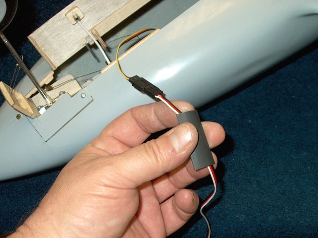
Install a 12" servo extender and
heatshrink the connection so it cannot come apart
| |
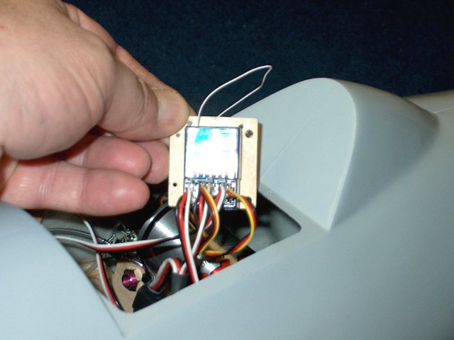
Cut a board to fit the receiver with 1/4"
overlap on all sides | |
Plug the servo wires in the receiver, then
dress and tie wrap the wires. Drill two plate mounting holes
along the front edge and through the fuselage
| |
Use some #2 screws to install the receiver
plate behind the cockpit | |
Coat the top of the screw heards with lead
from a pencil. Install the cockpit and press down on the
screws to transfer the hole locations to the cockpit
bottom | |
Drill out each hole so it clears the head
of the respective screw | |
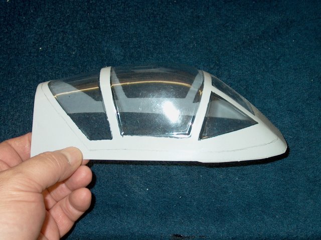
Rough cut out the canopy with
scissors | |
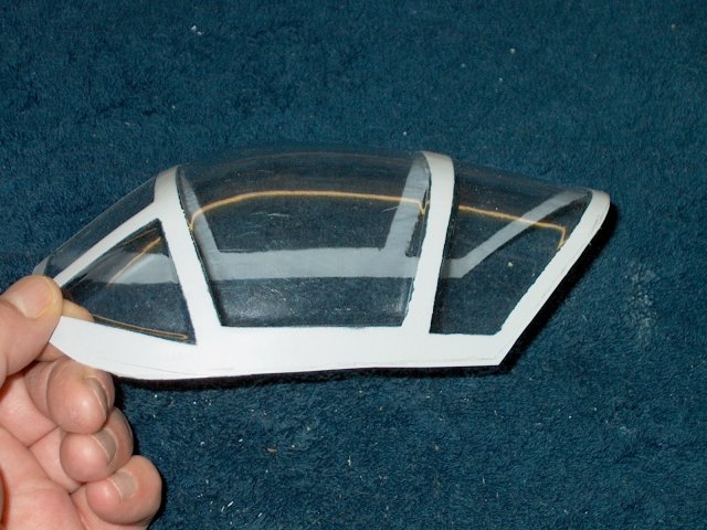
Trim the canopy to fit, but be sure not to
trim too much, especially on the forward sides as they need to
cover the Cockpit floor | |
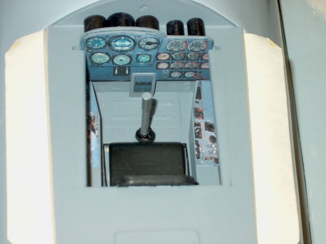
Now is a good time to build a scale
cockpit if you wish | |
Apply masking tape along the bottom edges
of the cockpit as shown | |
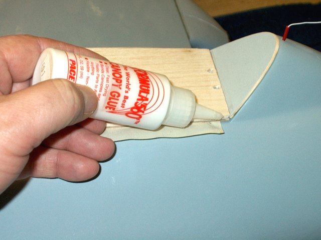
Install the cockpit on the fuselage, then
apply RC-56 canopy glue along both side edges
| |
Install the canopy and fold the tape
upwards to hold it in place while the glue dries. You can tape
down the front of the canopy to make sure it is flush with the
front of the fuselage hump | |
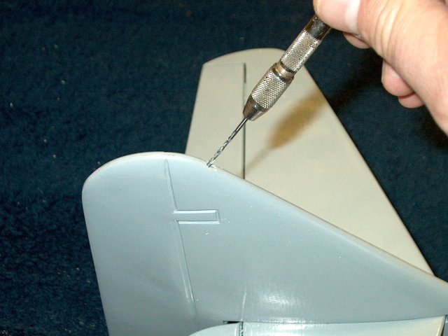
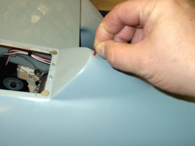
Antenna installation can vary depending on
your radio. Shown is a method to install a semi-scale antenna.
Drill a hole in the vertical stab using a 5/64" bit
| |
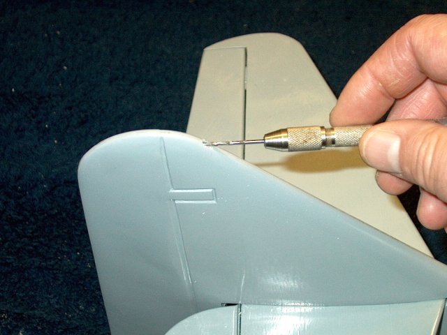
Once through, angle the drill forward and
drill again through the stab. The first hole will allow the
bit to remain in place and not slip while drilling
| |
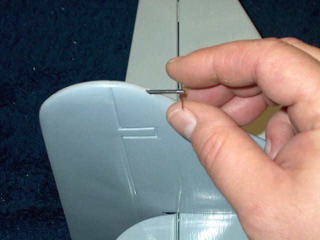
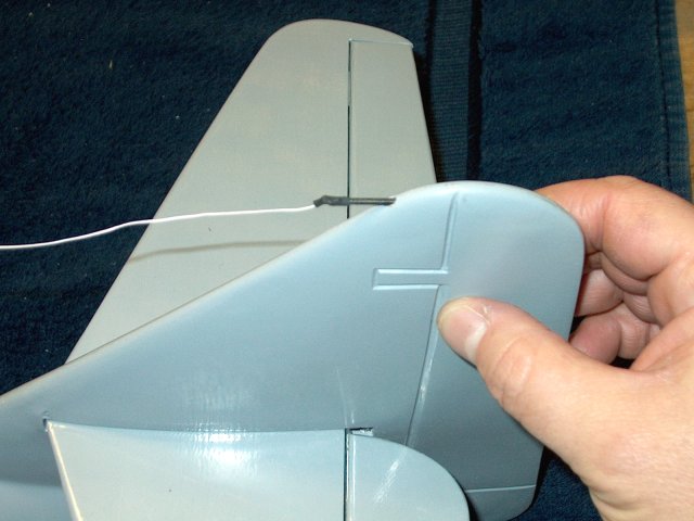
Install one of the tailwheel wire rods
from the tailwheel kit you used to wire the nosegear steering
assembly. A piece of wie installed through the hole helps with
the turning | |
Drill a hole just behind the canopy and
install a 1 1/2" long plastic tube from a WD40 oil can spray
tube. Make sure your antenna can fit through the tube. The
antenna for the Berg receiver fits perfectly
| |
Run your antenna through the fuselage,
then through a tensioner shown in the next photo and tie it
through the rod hole and cover it with a small piece of
heatshrink | |
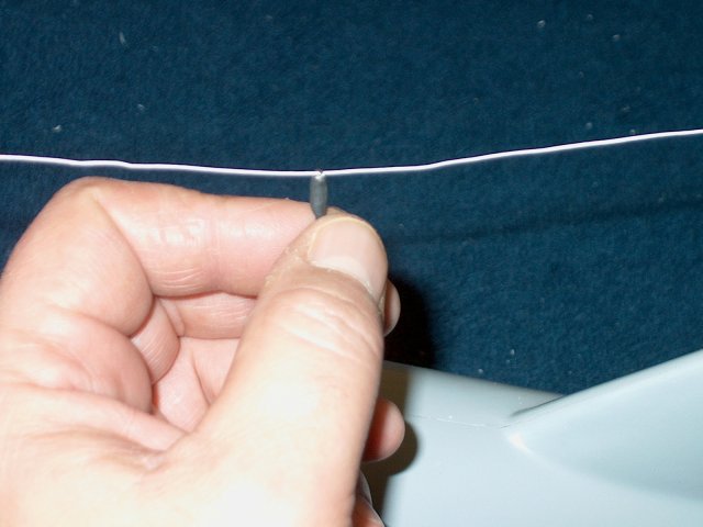
slide the tensioner in place. it is made
from a small wire, looped and sodered, then glued to a small
diameter elastic string. Heatshrink covers the assembly
| |
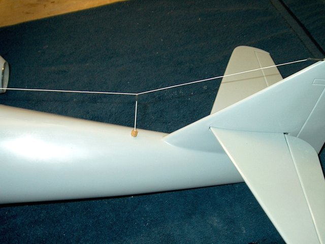
Build a string mount from 5/16" dowel.
coat in in CA, then sand and Drill a 1/16" hole down through
the dowel. Drill a 3/32" hole in the side and tapit, then
install a 4-40 set screw. Drill the bottom of the tube with a
3/32" bit about 1/8" deep, then install a piece of aluminum
3/32" OD tubing as a mount, making sure id does not sit so
deep that it blocks the setscrew. Drill a hole in the fuselage
for the tube, then epoxy the assembly in place. Install the
eleastic through the top hole and down through the tube into
the inside of the fuselage, adjust the tension and lock down
the set screw | |
Cut a piece of 1/64" ply and epoxy it in
place as shown, applying epoxy only to the hinge
| |
Tape the area with stick side up under the
hinge and ply, then apply epoxy to the top side of the
hinge | |
Install and position the door, then fold
the tape up to hold it in place | |
Tilt the door up and clamp the area while
the epoxy sets. Repeat this procedure for the second
door | |
IF you plan on using a BEC, install it per
instructions. Apply servo tape to the bottom and stick the BEC
unit to an upper side walll in the cockpit area. Dress the
wires and tie wrap them as necessary
| |
Install a battery, then turn on your radio
and receiver. Set Elevator travel to 8mm up and down
| |
Set Aileron travel to 8mm up and 6-8mm
down | |
CG is located 85mm from the leading edge
of the wing root. Mark the location on each wing so you can
check CG in the field | |
The door closing wire is bent to work as
shown. Adjust the wire so the door closes and does not hang on
the wire | |
A wood block is cut and drilled through
the top through the front of the bar at two locations for the
inner fuselage door tensioning wires. It is glued in place as
shown, then fine .020" wire is cut and routed to the door
tubes as shown. These doors work similarly to the main
nosegear door, so that they spring open and closed
| |
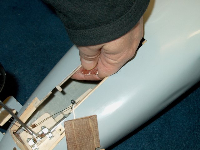
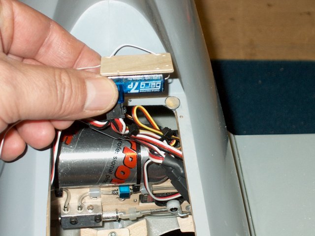
The batteries are installed in the very
front sides of the model. Start by sanding the area for a
velcro strap | |
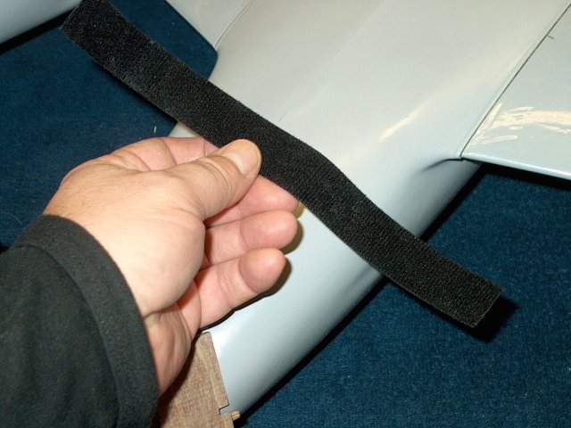
Cut four 10" long pieces of Velcro strap.
This is the double sides strap with cloth on one side and
hooks on the other | |
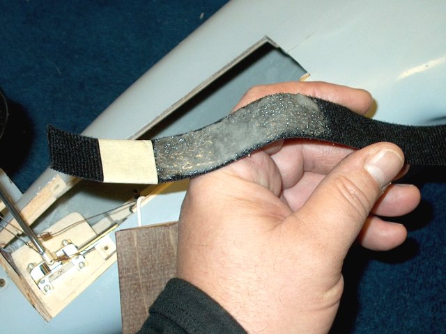
Apply a thick coat of epoxy and fiberglass
mil to the strap 2" from one end and about 3" long
| |
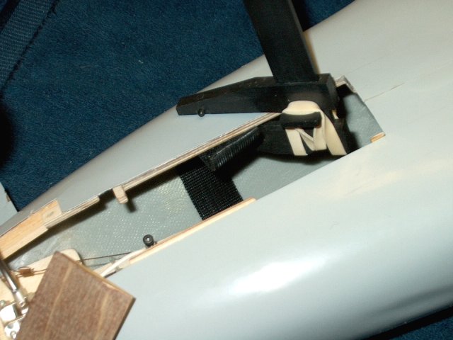
Slide the strap in place with the front
edge just behind the rear of the steering servo tray. The glue
holds the strap to the floor and side wall. Do not glue past
the inner ply reinforcement and trim off any excess so the
door can close | |
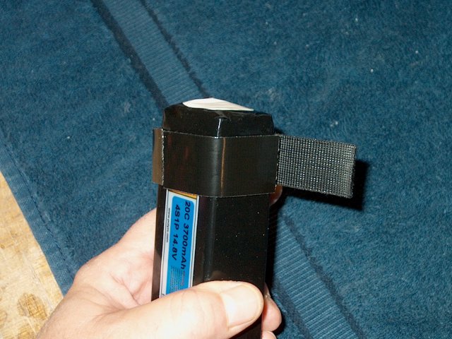
At the rear, take a second strap and wrap
it around a 4S battery. Apply a industrial self stick 1" wide
strip of velcro hook to the bottom and side of the strap as
shown. Install it in the fuselage from the cockpit, then when
it is in place, remove the battey and lake sure the velcro is
seated. Repeat these steps for the other battery
| |
The batteries are installed from the
cockpit, moved forward and strapped in place from the
nosewheel opening, then the rear straps are installed
| |
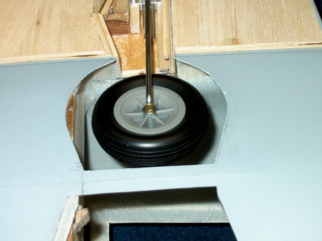
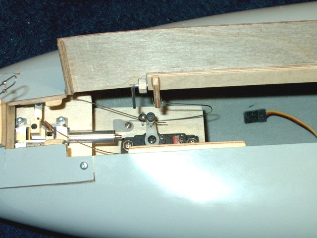
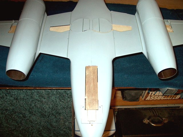
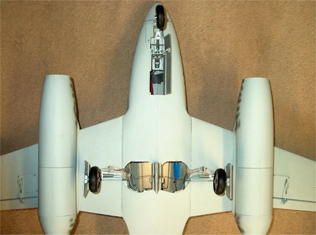
Air Power RA-260 Retracts shown in the
down position | |
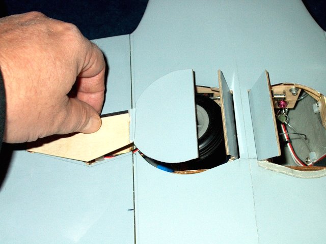
The photo shows how the wheel closes the
inner fuselage door on the mains | |
Gear is shown in the retracted
position | |
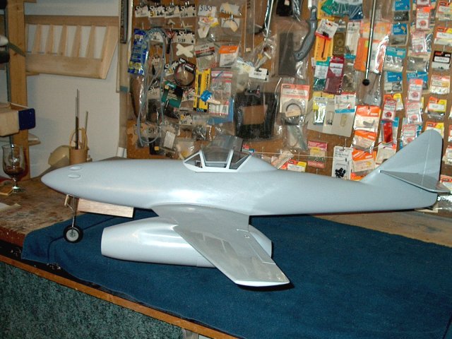
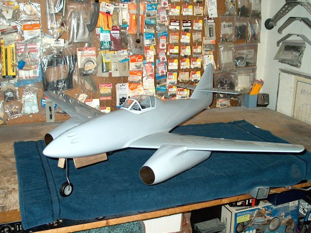
Side view showing a slight nose high
stance of the ME-262 | |
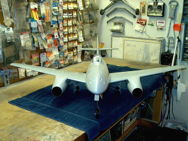
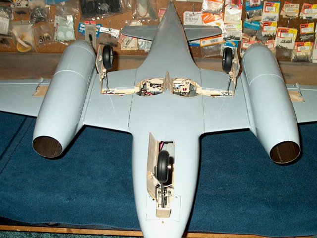
Front view showing the Air Power Retracts
and landing gear | |
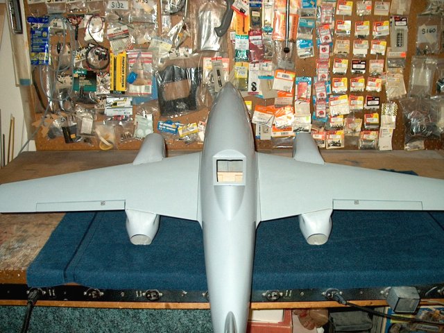
The HET-RC ME-262 twin EDF Jet with
Airpower RA-260 Retracts from Warbirds-RC. The main assembly
is completed and the model is ready to be painted in your
choice of color schemes | |
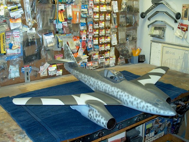
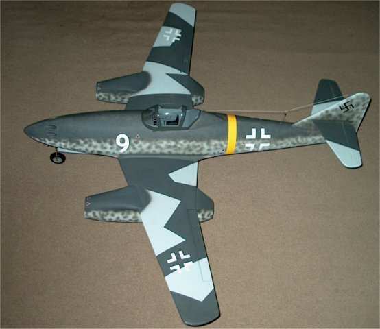
Paint your model in a color scheme of your
choice | |
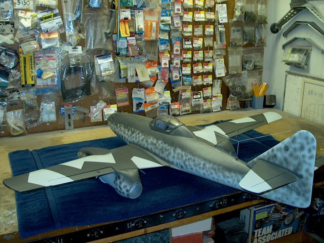
A two tone leopard scheme was used for the
build model | |
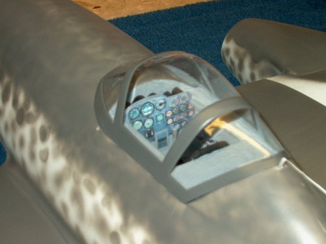
Detail your cockpit as desired
| |
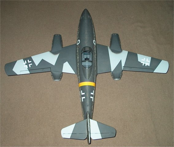
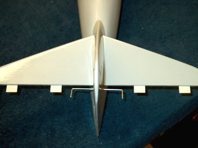
ME-262 Top View
| |
ME-262 Side View
| |
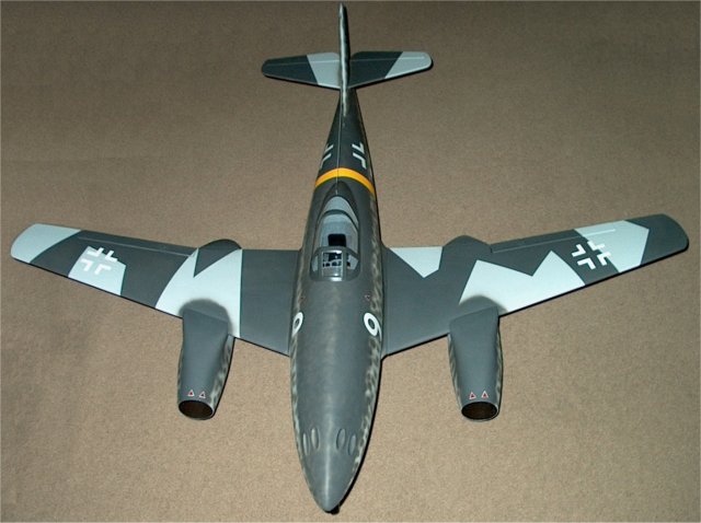
ME-262 Forward View
| |
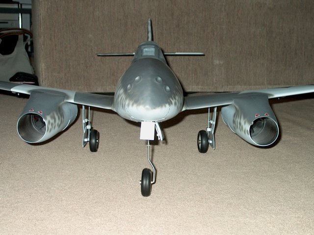
ME-262 Front View of Gear
| |
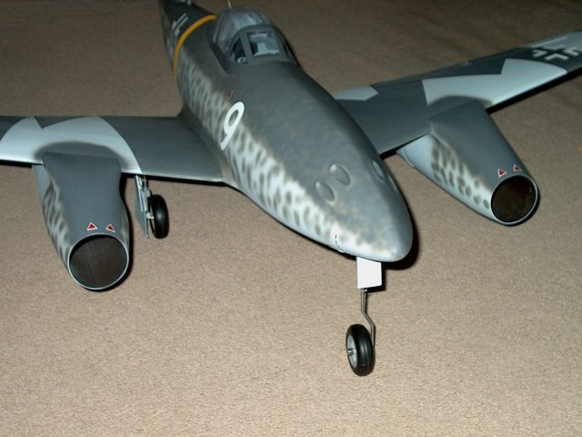
ME-262 Side View of Gear
| |
ME-262 Gear Down
| |
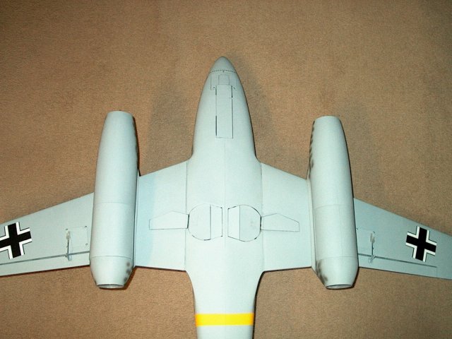
ME-262 Gear Up | |
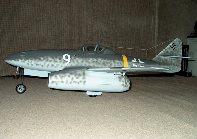
ME-262 Side Profile
| |
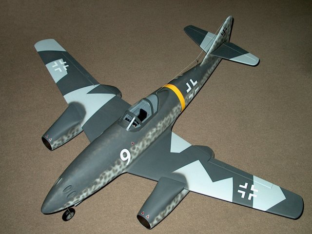
The HET-RC ME-262 Swallow Twin EDF Jet
| |

This Website and all documents herin are Copyright © 2012 www.scalerocketry.com -
All rights reserved.
| |