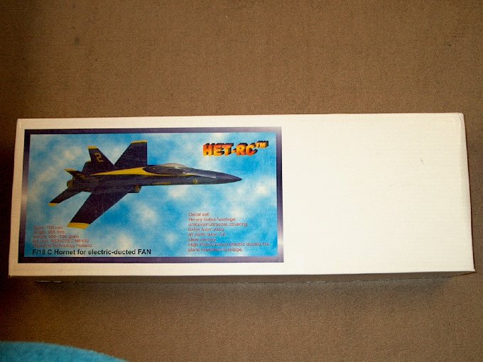
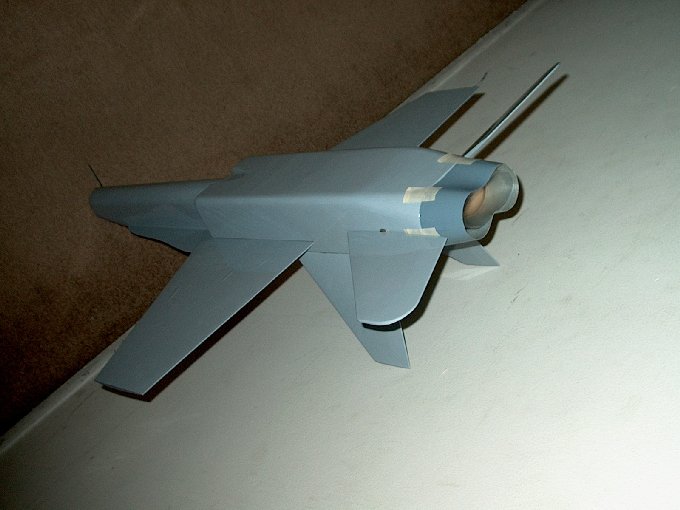
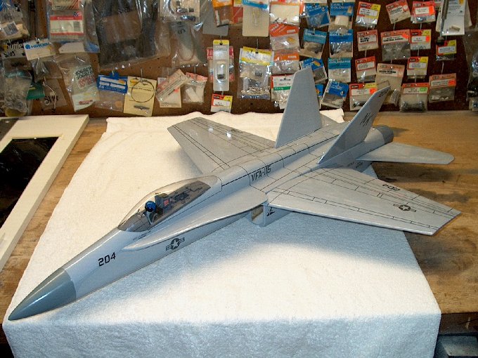
01 - The "Bug"...HET-RC's FA-18 Hornet.
| |
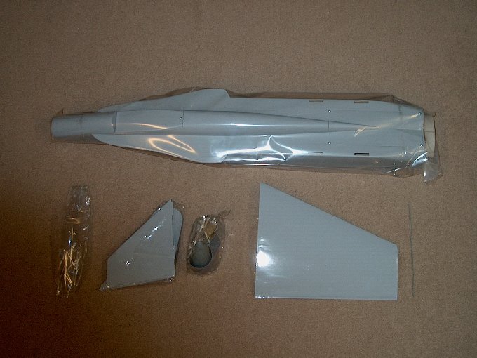
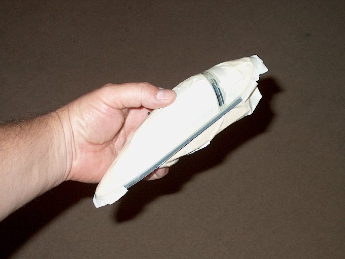
02 - It comes very well wrapped with wings
and tail feathers taped inside the lids so they won't move.
Take care by removing the tape, then they wings and such will
come right now. | |
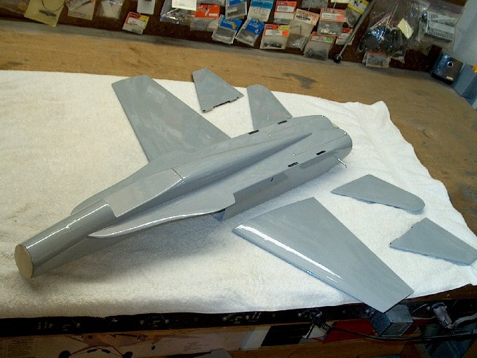
03 - The model and its components.
| |
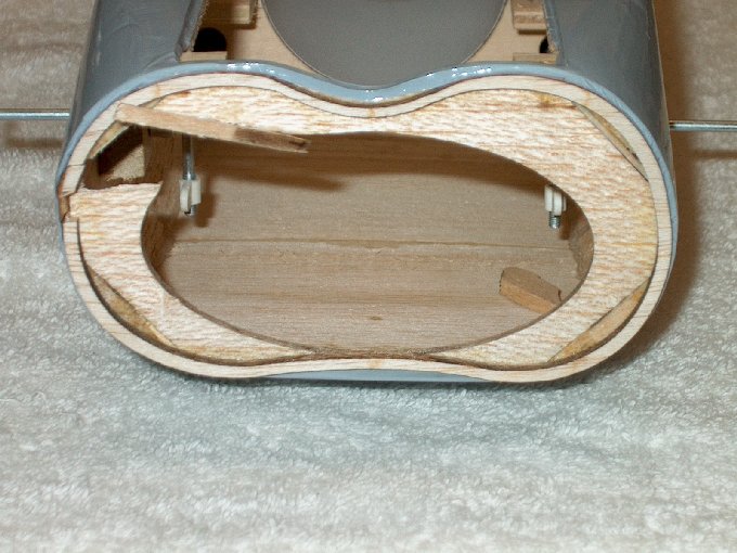
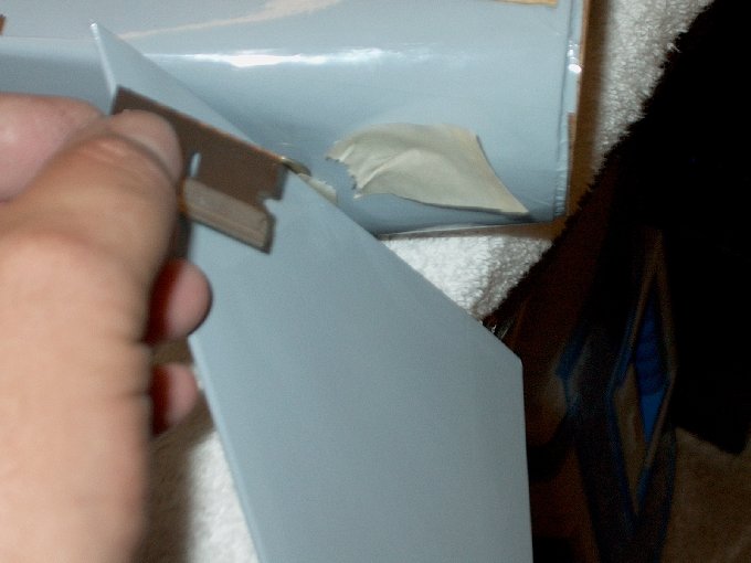
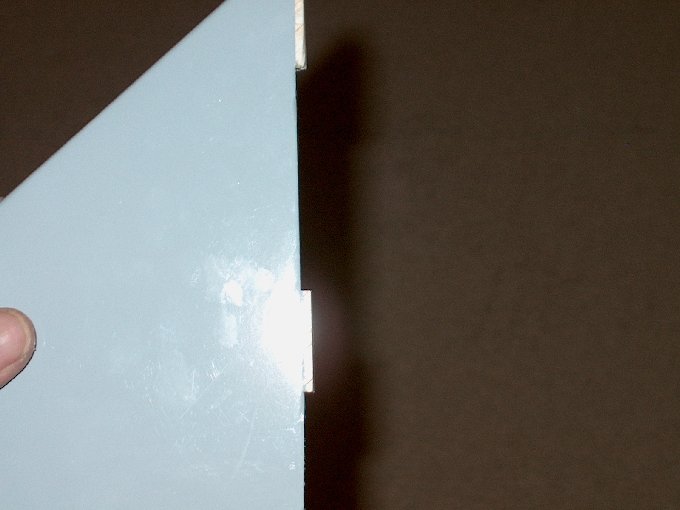
04 - A bit of shipping damage...
| |
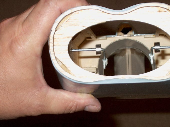
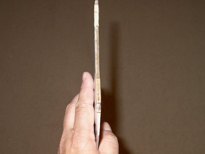
05 - ...very easily fixed! This is a top
quality ARF. | |
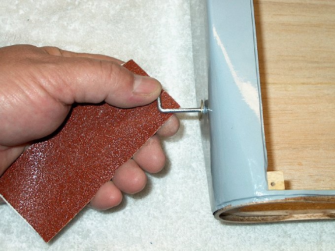
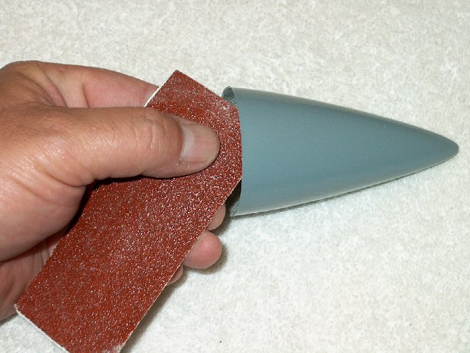
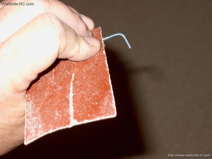
06- Sanding the Horizontal stab control
wires with 60 grit. | |
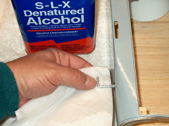
07 - Wipe away any excess sanding residue
with alcohol and towel. | |
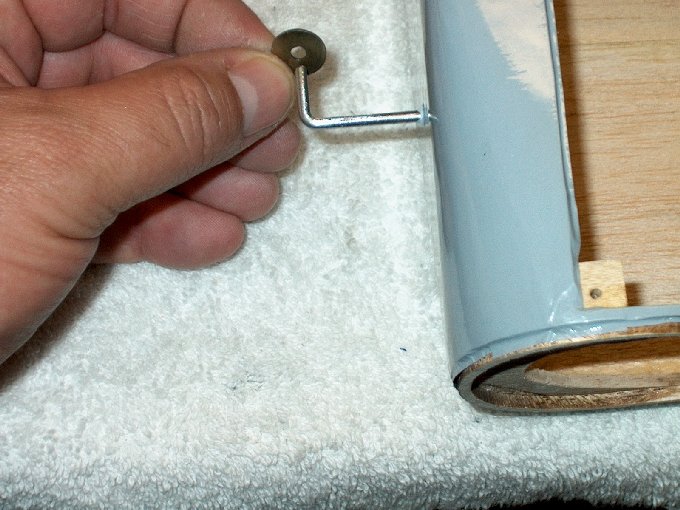
08 - Install the washer.
| |
09 - Ready for assembly.
| |
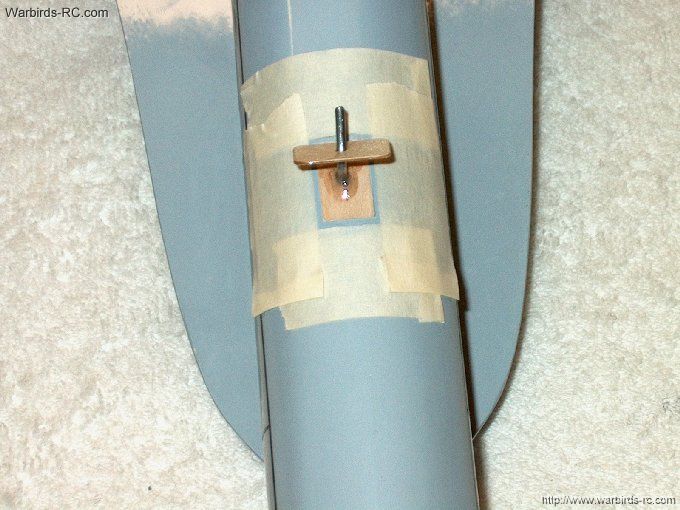
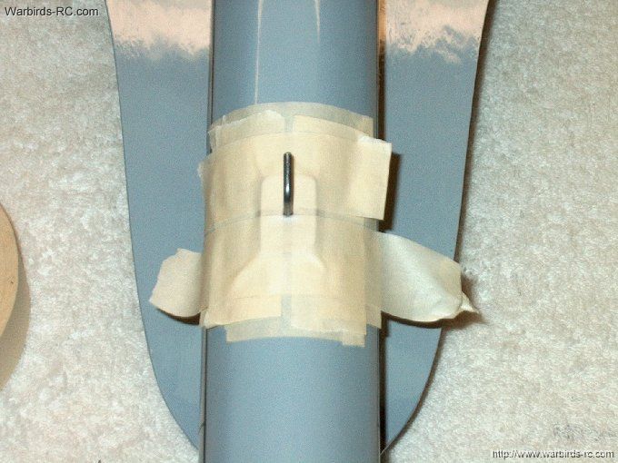
10 - Masking used to keep excess epoxy
away from the fuselage. | |
11 - Dry fit of the stab plate.
| |
12 - Nothing's too good for the model...
mixing it up. | |
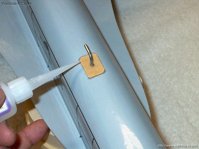
13 - Epoxy applied to wire and plate, then
plate pressed over wire. | |
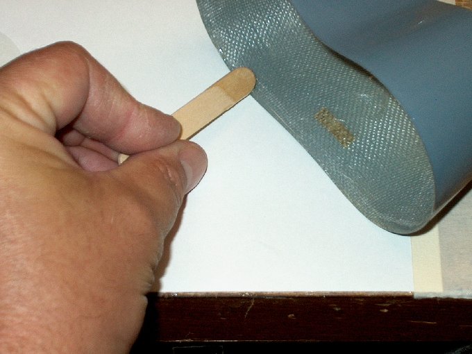
14 - Stick used to apply epoxy inside the
stab. | |
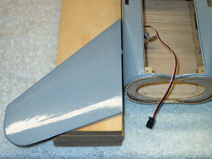
15 - Installing the stab.
| |
16 - The stabs will "self-bottom" when
fully seated over the plate... be sure to push them on all the
way. Clean up the excess epoxy with alcohol and a paper
towel. | |
17 - Removing the tape.
| |
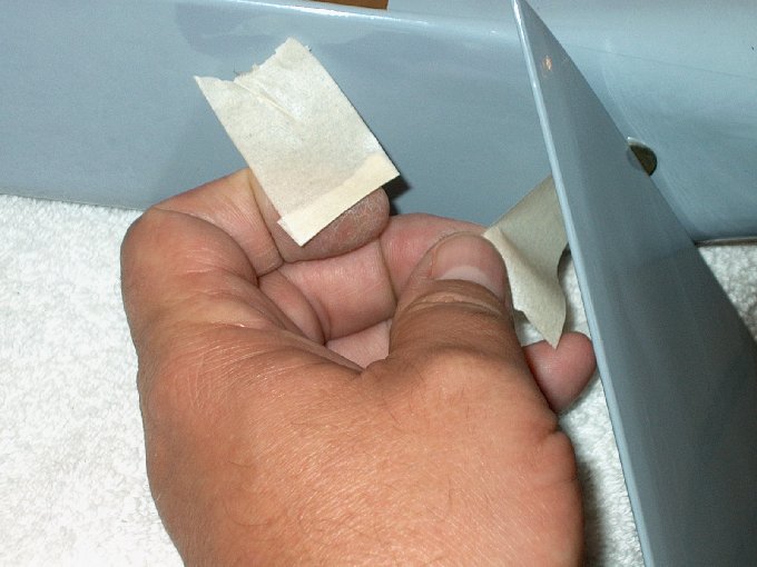
18 - Tape removed.
| |
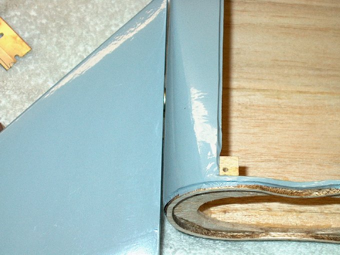
19 - Do some final clean up, making sure
no epoxy wicked into the joint. | |
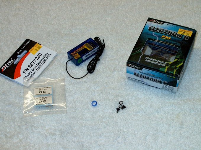
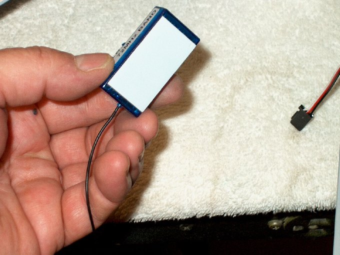
20 - A dual conversion receiver is
recommend for safety. | |
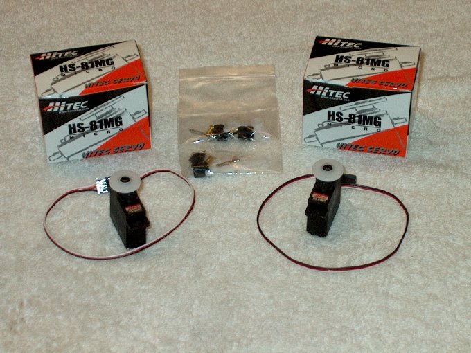
21 - I decided to go with the Heavy Duty
Metal Gear servos, although HS-55's have worked well... it's
your choice. | |
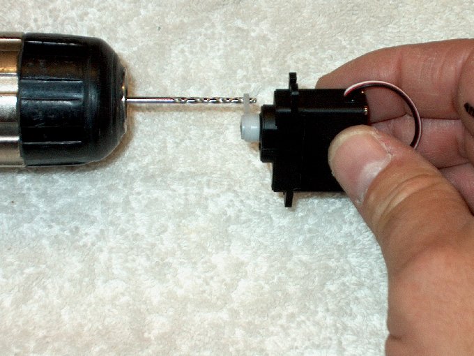
22 - Drilling out the horn with a 3/32"
bit. | |
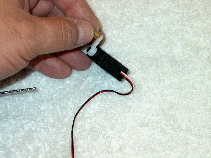
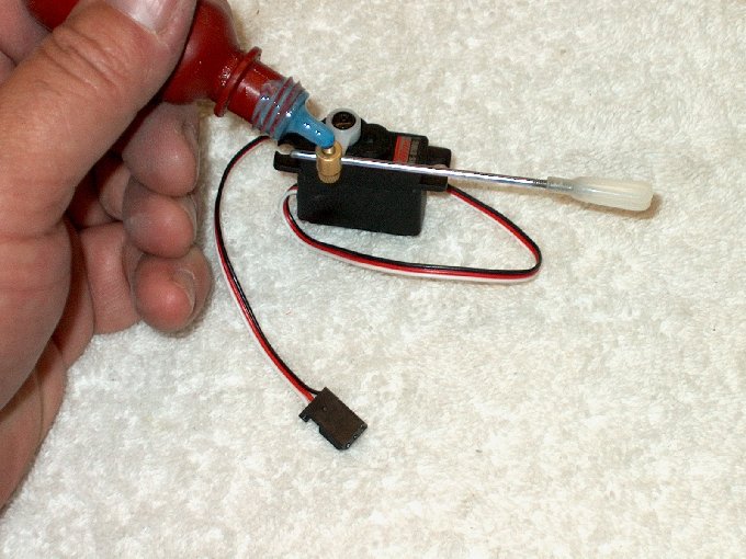
23 - Installing the supplied EZ
connector. | |
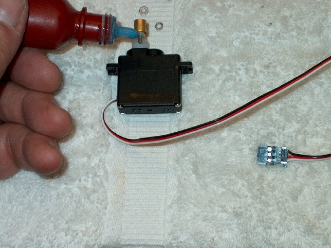
24 - Some Lok-Tite applied to the threads
for insurance. | |
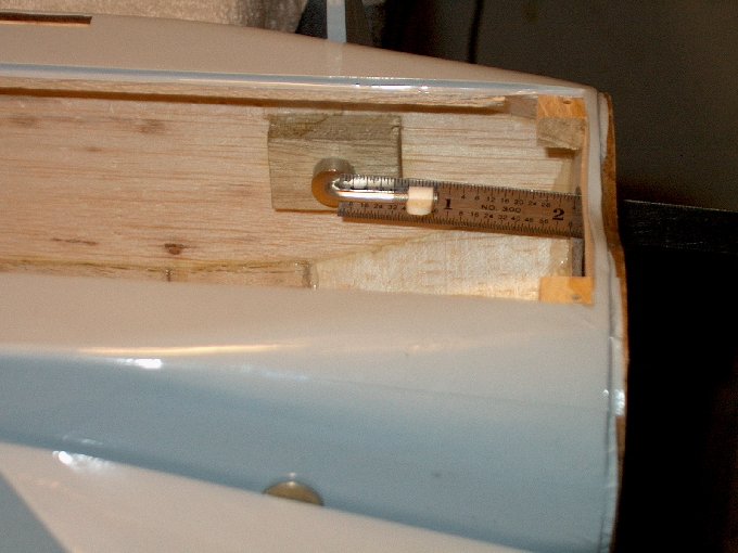
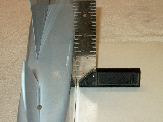
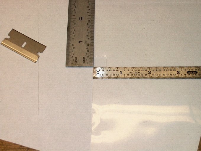
25 - Measuring the horn connector... make
sure both sides are the same distance.
| |
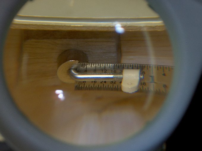
26 - I set each side to 5/8" from the
elbow to bottom of the horn | |
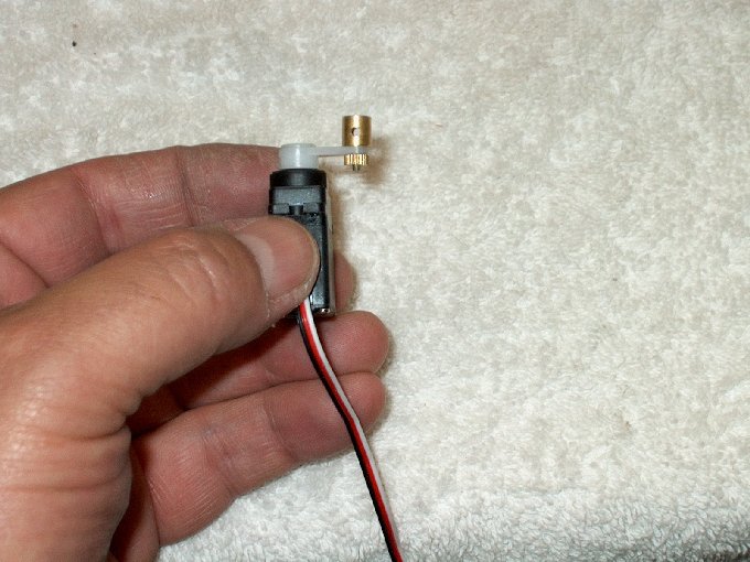
27 - The knurled nut was a very nice
touch. make sure the unit can spin in the horn without
binding, but you don't want any slop either.
| |
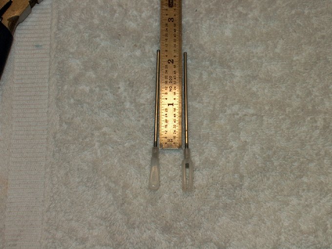
28 - I opted for larger 2-56 nylon clevis'
and cut two rods so 2 1/4" protruded from the bottom of each
clevis. | |
29 - Rod installed in the EZ connector and
a drop of Lok-Tite added. | |
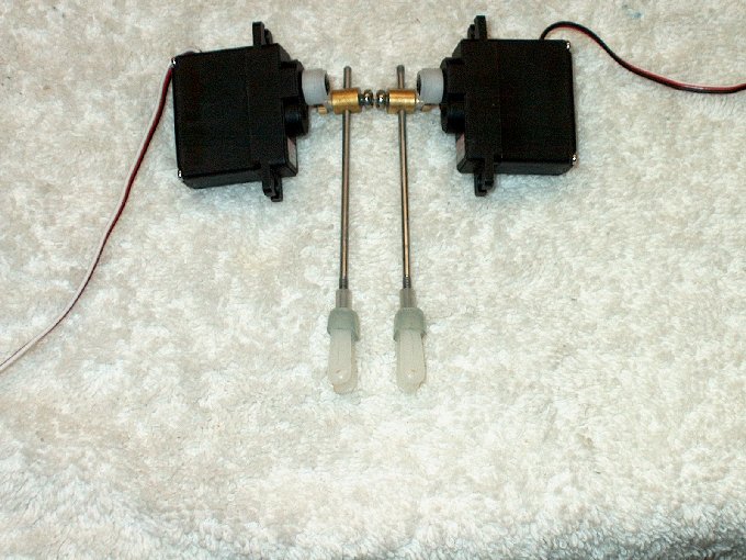
30 - Rod assemblies completed. The set
screws were shortened a bit for convenience.
| |
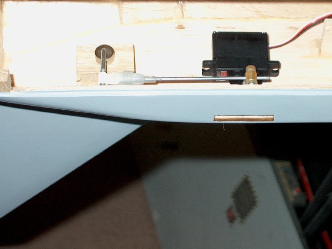
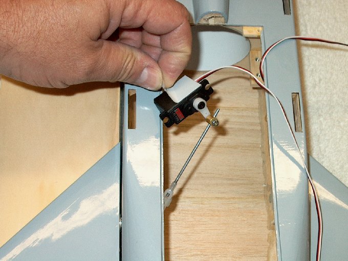
31 - Test fitting the servo... a piece of
medium fuel tubing is used as a clevis safety.
| |
32 - Set the stab to "zero" incidence when
installing the servo assembly... it should run parallel with
the fuselage. | |
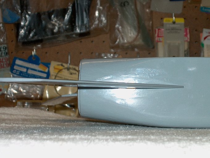
33 - A block up was used to keep the stab
"horizontal". | |
34 - Installing the servo... the receiver
was hooked up and turned on along with the transmitter so the
servos center before adhering them to the inside.
| |
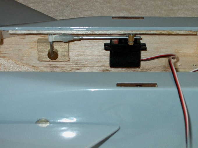
35 - Installed carefully, making sure the
control rods is parallel to the fuse top.
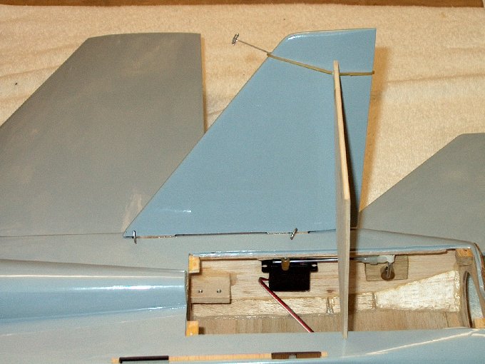
| |
36 -Servos installed. Now is a good time
to add the reinforcement mod to the model in the servo area
that is shwon at the end of this manual
| |
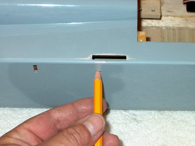
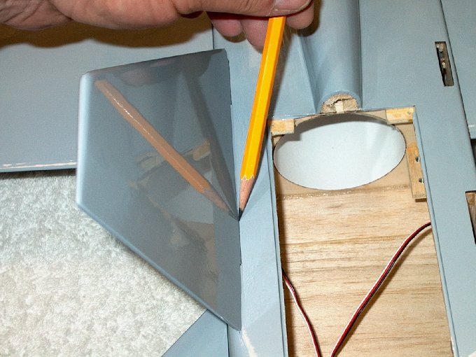
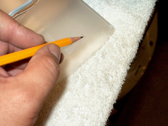
37 - Wing mounting time... a pencil was
used to "find" the guide holes. | |
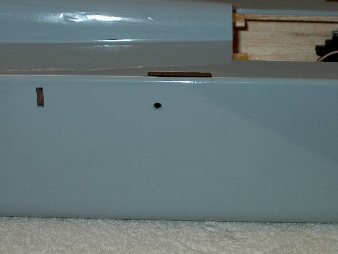
38 - Holes opened up.
| |
39 - A pencil used to mark the
fuse. | |
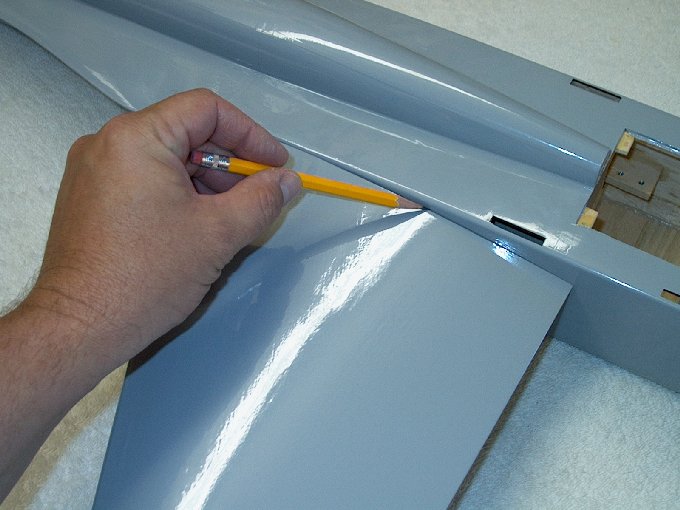
40 - Covering cut away carefully about
1/16" inside the pencil mark. | |
41 - Making sure not to cut too
deep. | |
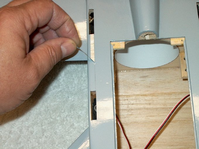
42 - Removing the covering.
| |
43 - A trimmed wing location.
| |
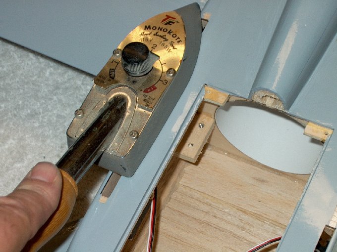
44 - Iron used to seal the fresh cut
edge. | |
45 - Other side being trimmed.
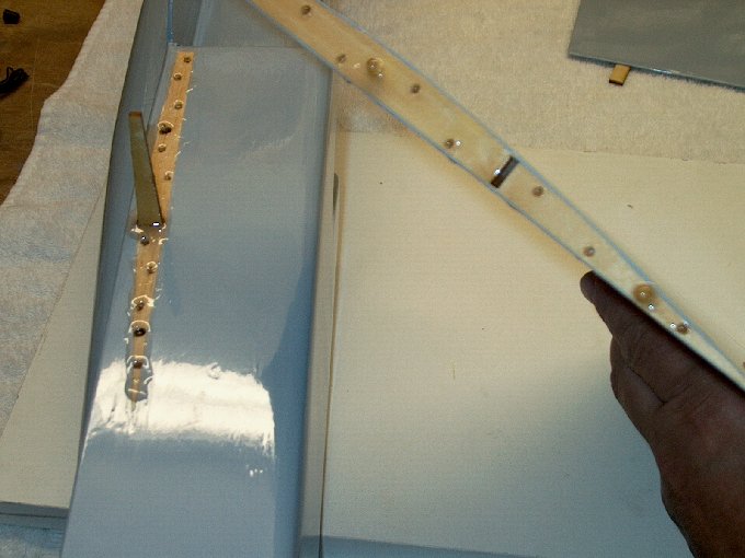
| |
46 - Drill 1/8" staggered holes in the
fuselage and wing about an inch apart from eachother as
shown | |
47 - Wing with holes drilled.
| |
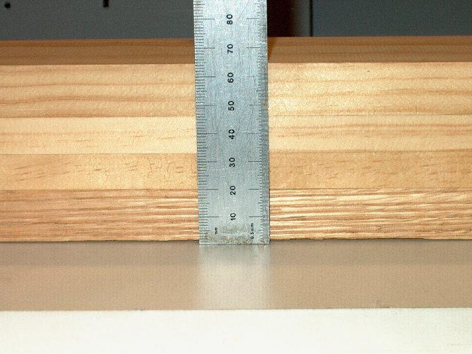
48 - A block was made 65mm high per
instructions and used to prop up the wing.
| |
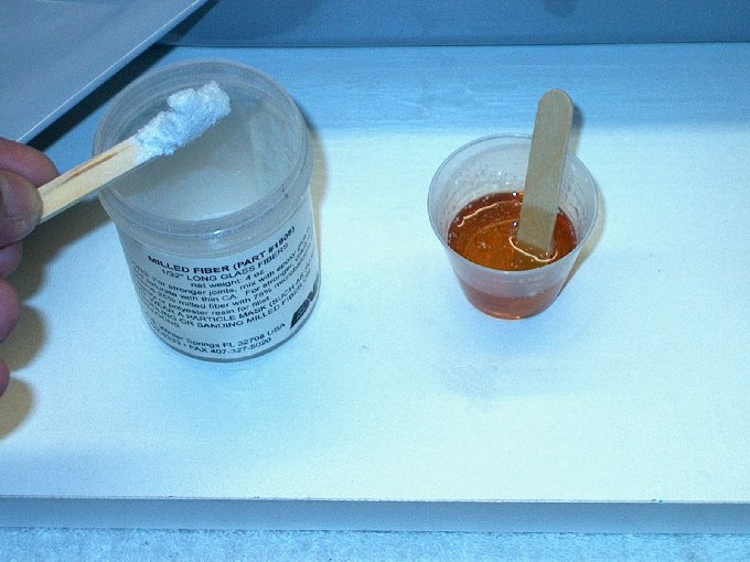
49 - Mixing up some BVM Glass Mil in with
epoxy. | |
50 - Epoxy applied to wing, ply spar and
fuselage side. | |
51 - Wing installed.
| |
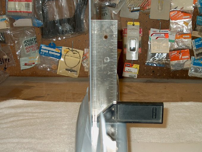
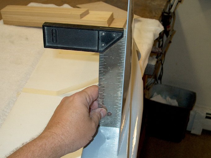
52 - Square used to true up the
wing. | |
53 - Fuse is also square to the table.
| |
54 - Epoxy was allowed to semi-set like
this so it wouldn't all drain to the bottom, but rather sit
where it needed to reside, allowing even dispersion. This
position also allows easy removal of the excess epoxy with
alcohol and a paper towel. | |
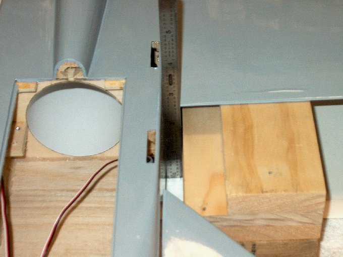
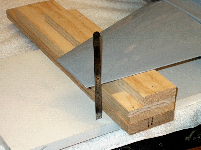
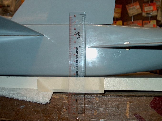
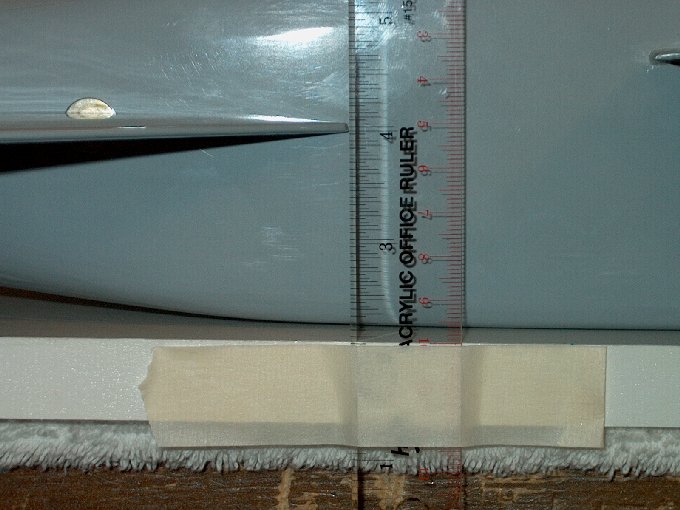
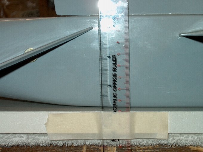
55 - Fuselage laid horizontally and inside
wing distance from board measured. | |
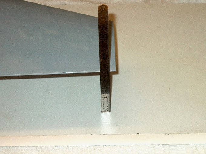
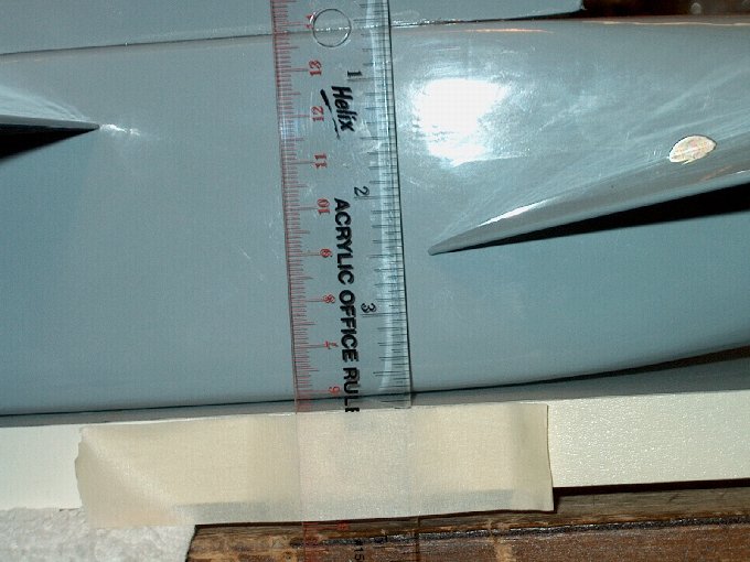
56 - Distance of wing tip from board was
measured and is the same as the root side distance, indicating
it was correctly installed. | |
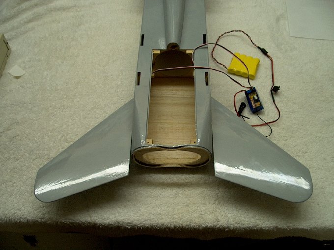
57 - Installing the other wing.
| |
58 - Epoxy applied to wing root.
| |
59 - Epoxy painted on spar.
| |
60 - Spar installed.
| |
61 - More epoxy applied to outside of
spar. | |
62 - Ready to install.
| |
63 - installing the wing.
| |
64 - Wing seated flush... excess epoxy
cleaned up. | |
65 - Wing squared up while epoxy
semi-sets. | |
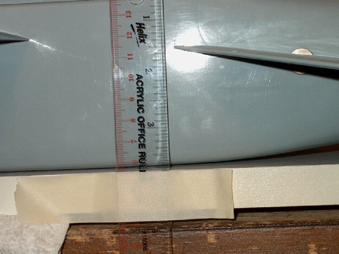
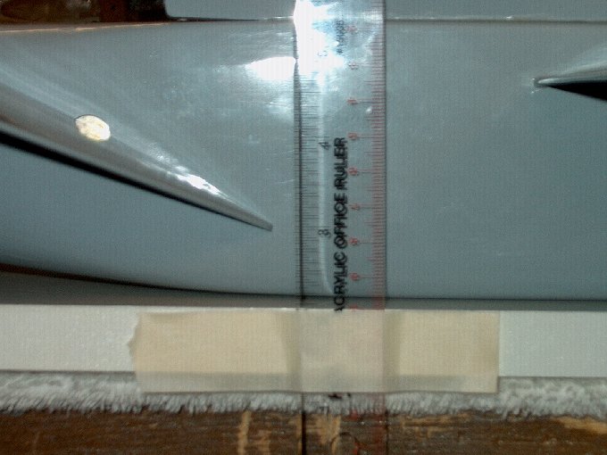
66 - Wing distance measured again... it
was the exact same height as the other wing.
| |
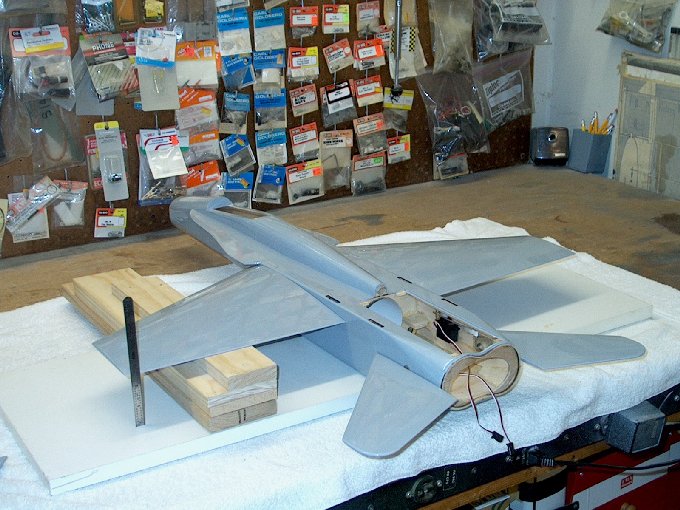
67 - Picture shows wing propped up.
| |
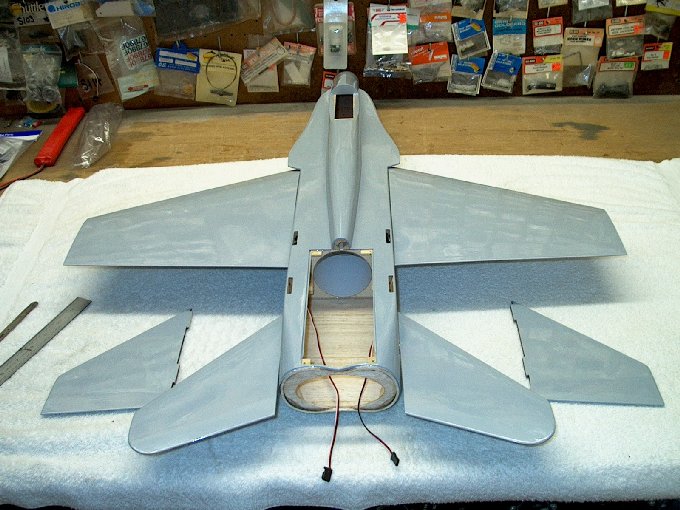
68 - Wings installed.
| |
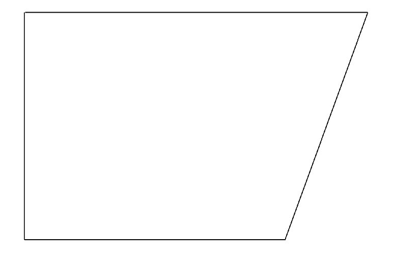
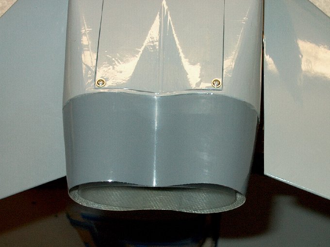
69 - Printable template for vertical stab
gauge. | |
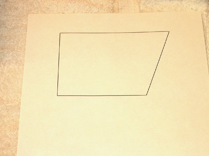
70 - A 110 degree gauge printed, then cut
out. | |
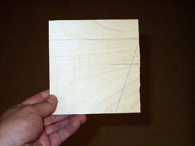
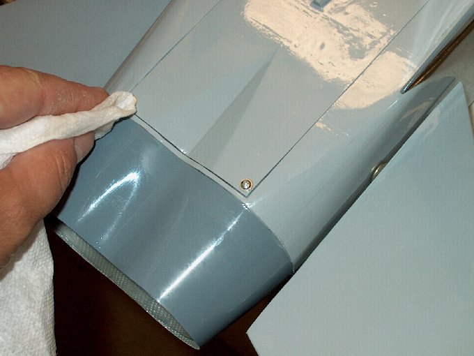
71 - I used the template to make a 1/8 ply
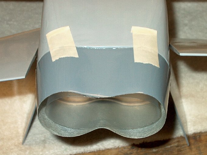
guage. | |
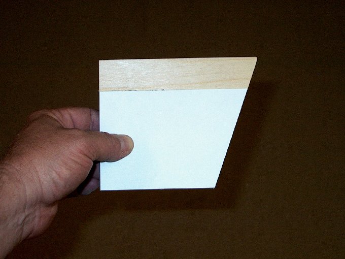
72 - Cut and ready to use.
| |
73 - Marking vertical stab
locations. | |
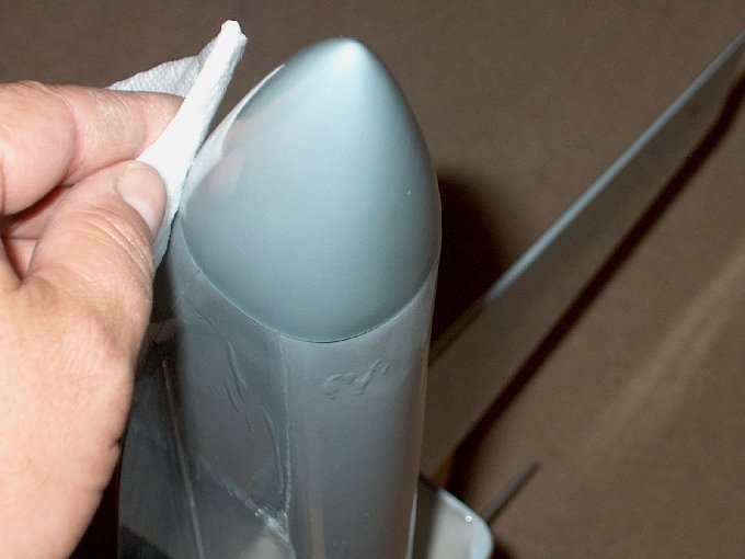
74 - Cutting away the covering.
| |
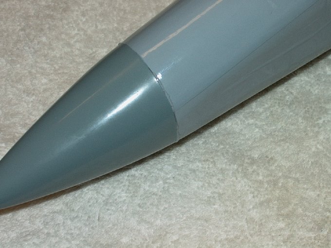
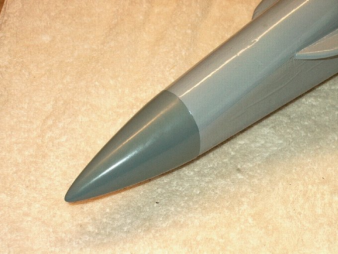
75 - Peel up reveals balsa for good glue
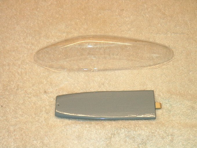
bond. | |
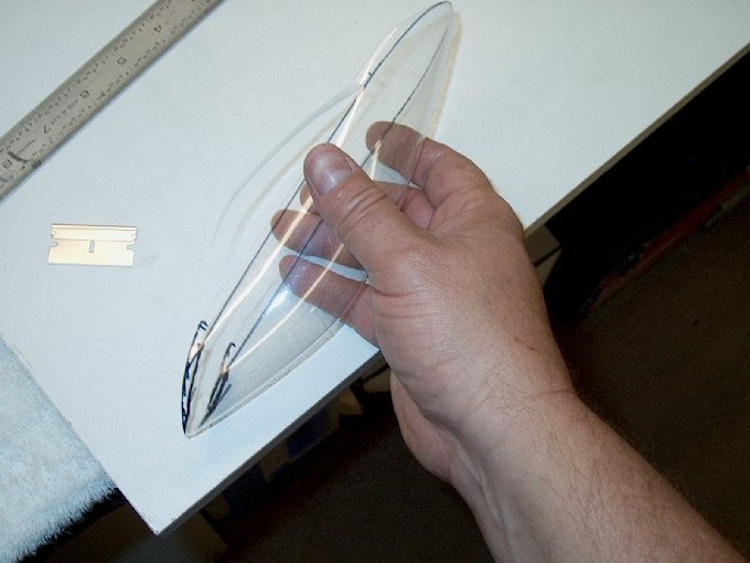
76 - Iron used to seal the
covering. | |
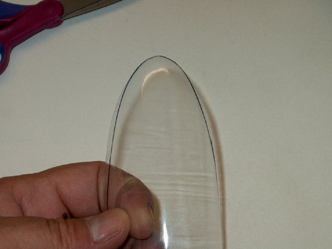
77 - Ready for stab installation.
| |
78 - Stabs are angled... check the bottom
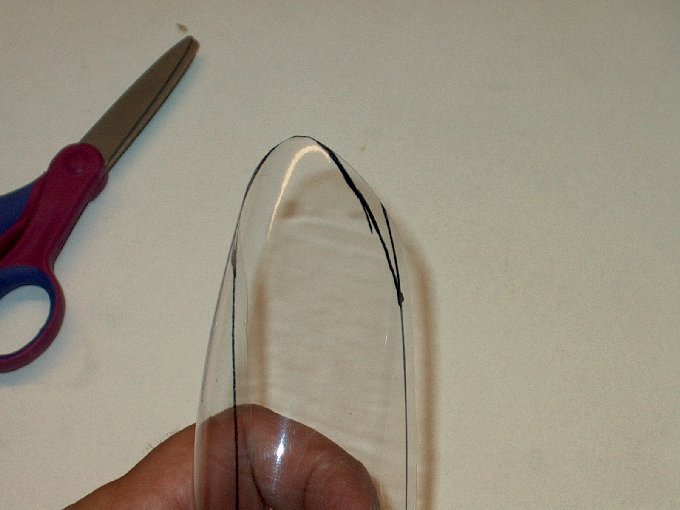
to make sure the correct one is used.
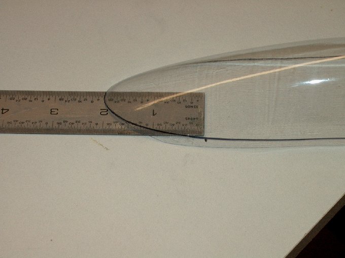
| |
79 - Marked left and right so they don't
get mixed up. | |
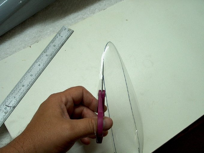
80 - Peel away excess covering before
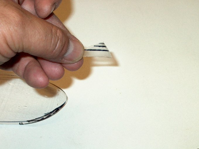
gluing. | |
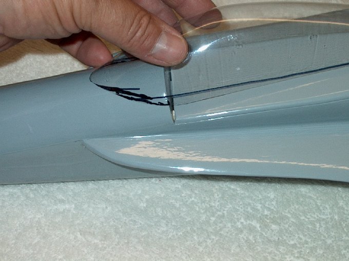
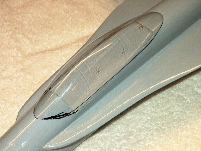
81 - Vertical stab ready to
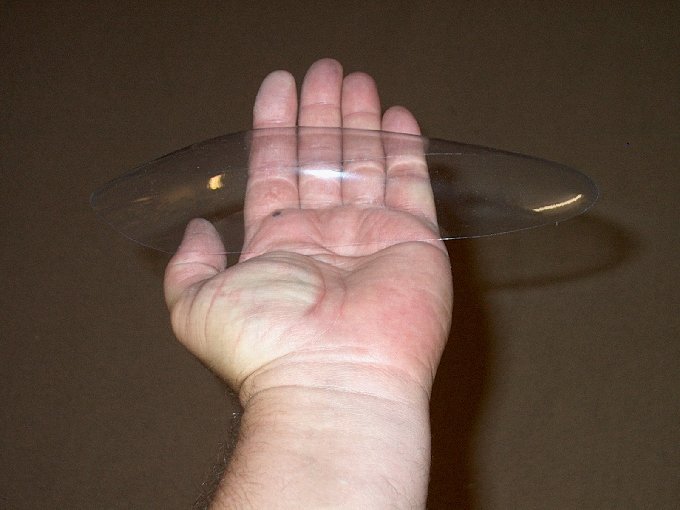
install. | |
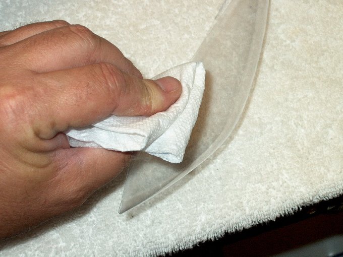
82 - Epoxy applied to stab.
| |
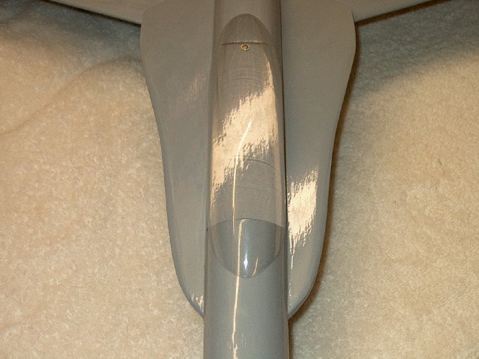
83 - Epoxy applied to fuselage.
| |
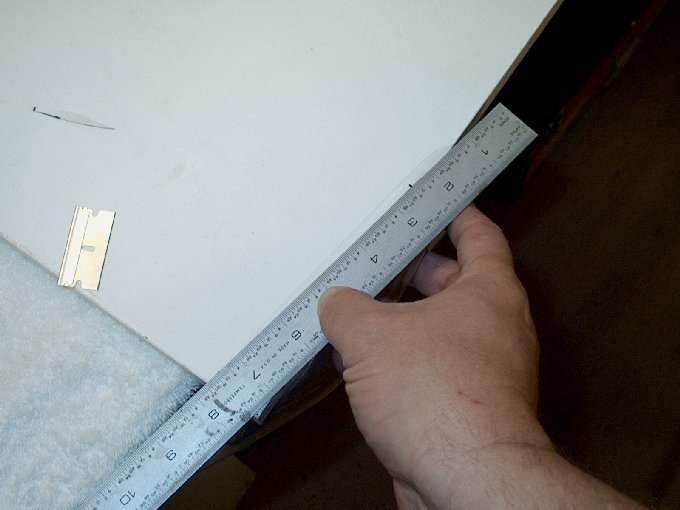
84 - Using the gauge to set the stab
angle... I finally found a good use for those GWS rubber
bands. | |
85 - Stab pinned at base while epoxy sets.
| |
86 - Second stab epoxied in place...
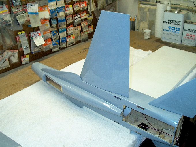
fillets were added to inside. | |
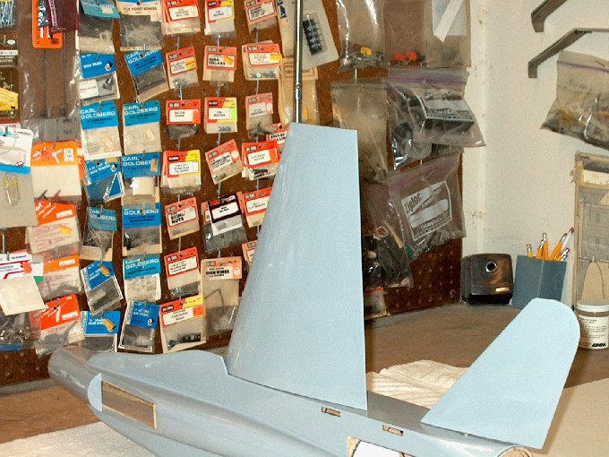
87 - Vertical stabs installed.
| |
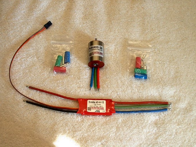
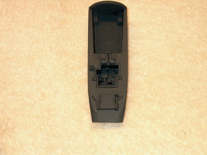
88 - The Kontronik power plant.
| |
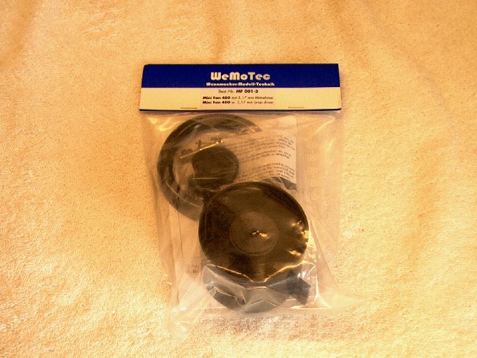
89 - Wemotec MiniFan 480.
| |
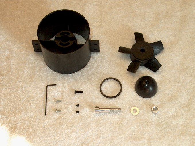
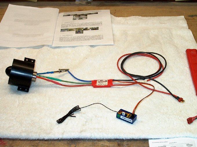
90 - Fan and all the parts. Note it comes
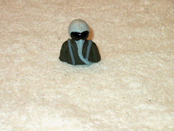
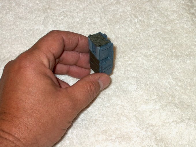
with two silver 2.5mm motor mount screws, but the Kontronik
takes 3mm so these weren't used. | |
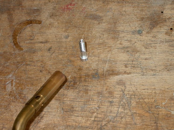
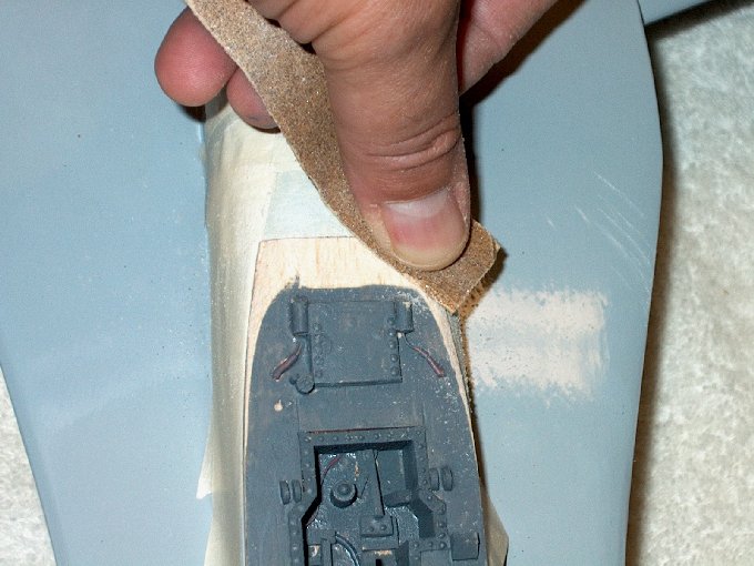
91 - Motor adapter being heated with a
torch so it slips on the motor shaft easily.
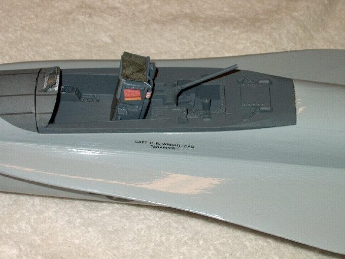
| |
92 - Adapter shaft installed.
| |

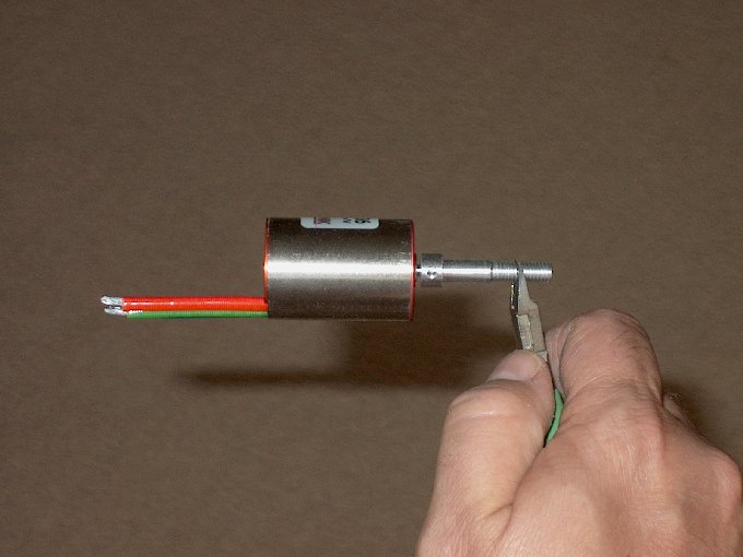
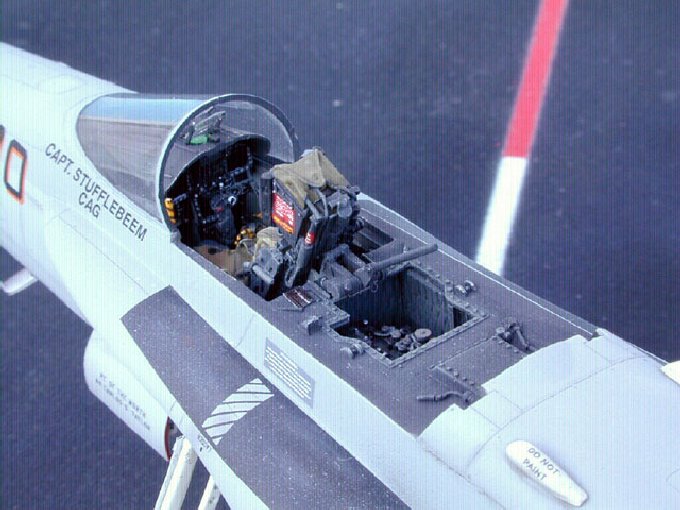
93 - Adding some Lok-Tite to the set
screws | |
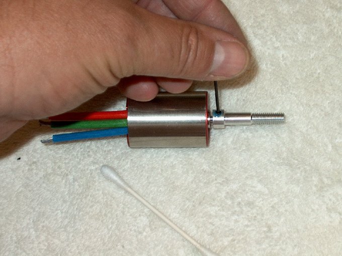
94 - Set screws installed... noted the
spacing at the base needs to be checked so the adapter is not
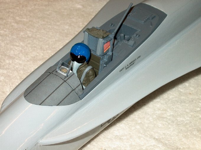
installed too far back or the fan will rub against the shroud
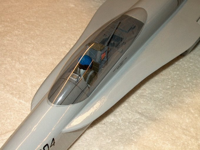
when installed. | |
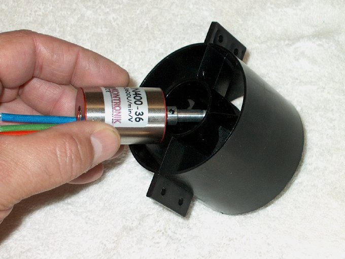
95 - Installing the motor in the fan
housing. | |
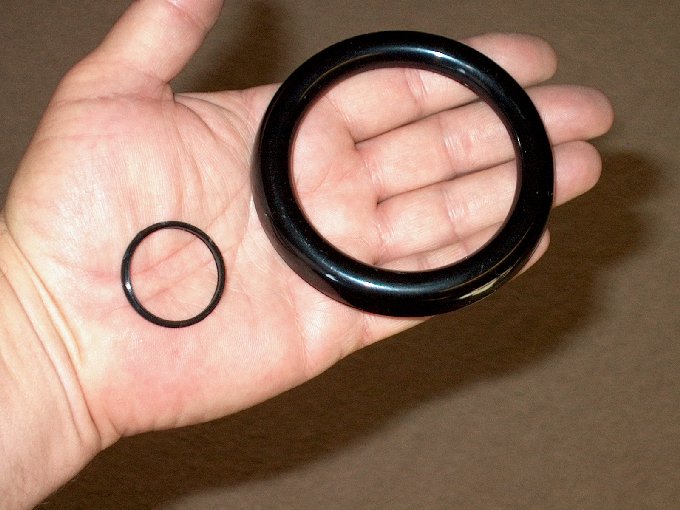
96 - Two parts not used for this
installation. Two parts not used for this installation. NOTE:
For those of us who don't check our fans on a regular basis,
it is recommended that you add the small spacer ring on the
rear of the motor. Over time, the motor screws can and will
slowly work itself loose causing the rotor to come in contact
with the inside of the shroud. This can result in the blades
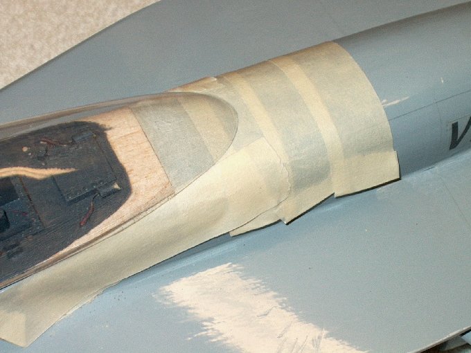
scraping and in some situations, breaking. Special thanks to
Al Mostek for this helpful tip. | |
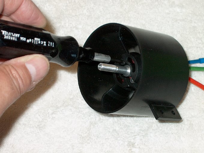
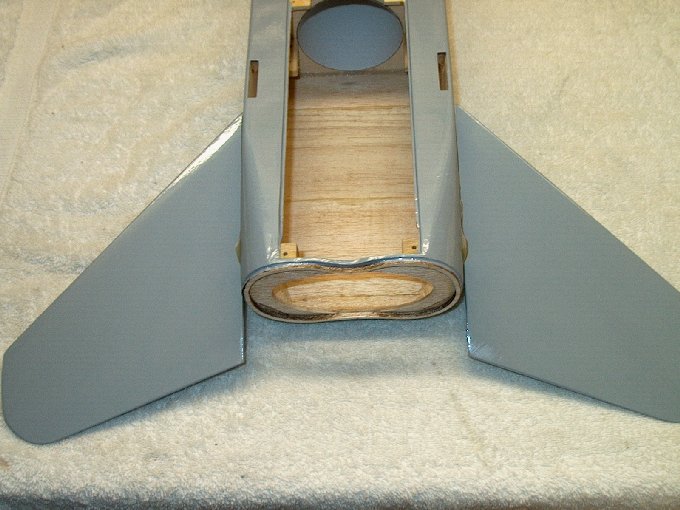
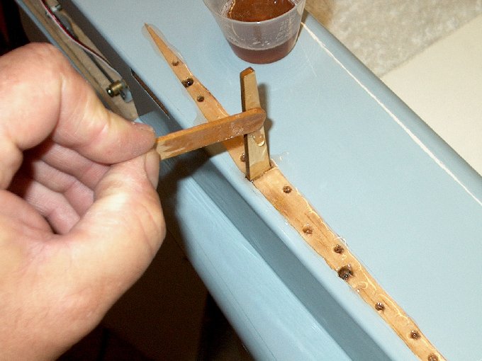
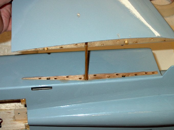
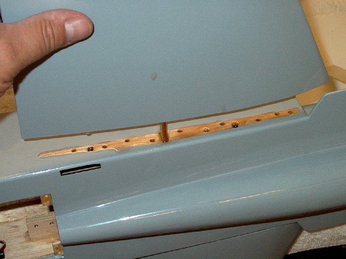
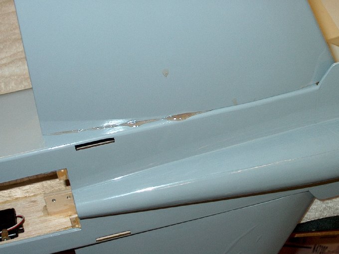
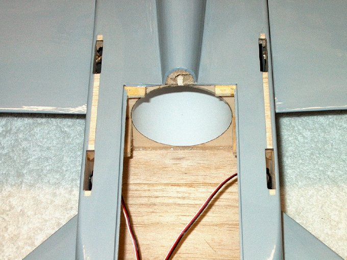
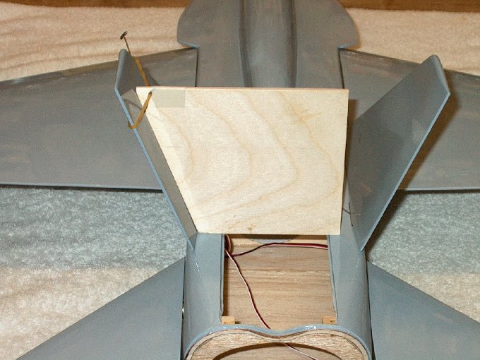
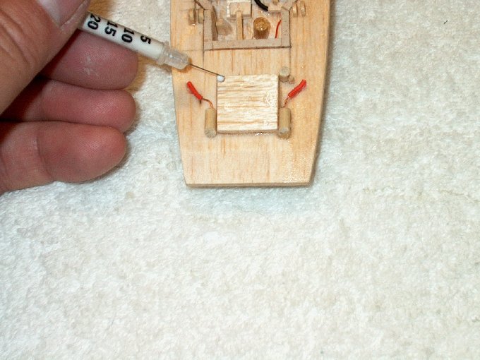
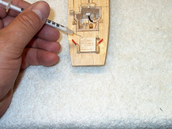
97 - Locking the motor down. I used the
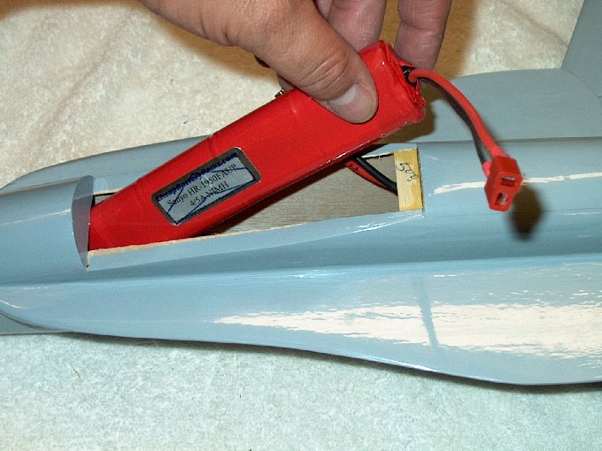
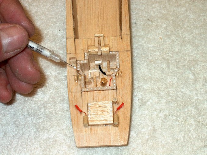
3mm hardened hex bolts to install. | |
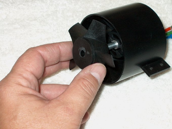
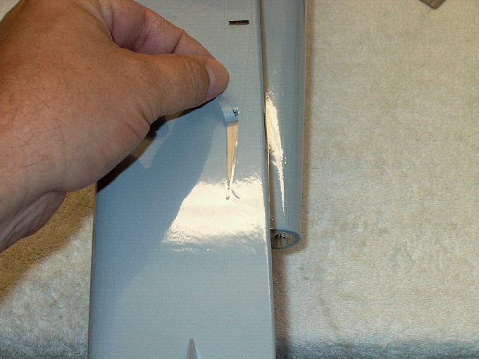
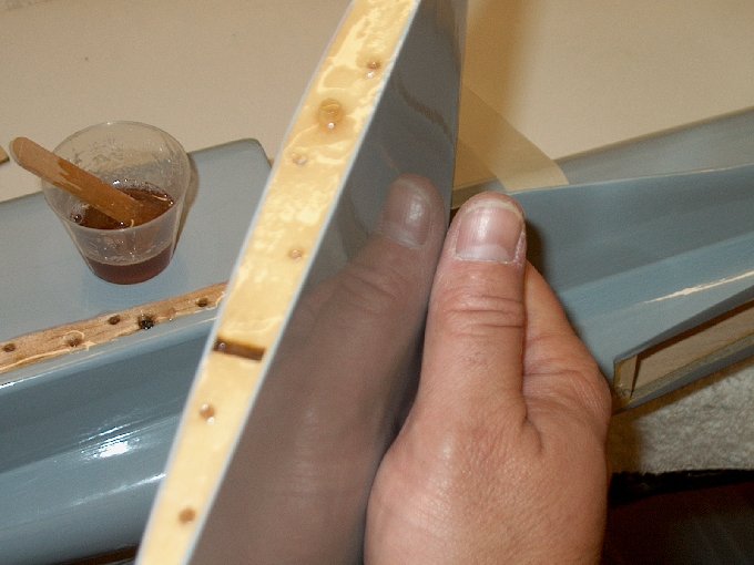
98 - Installing the fan.
| |
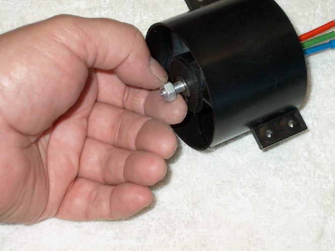
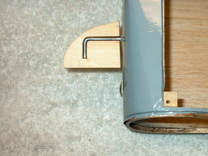
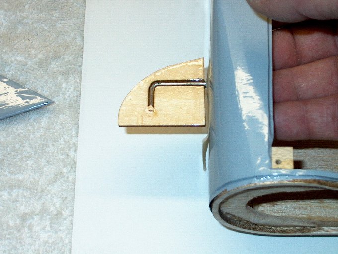
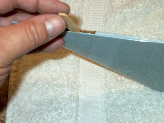
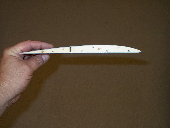
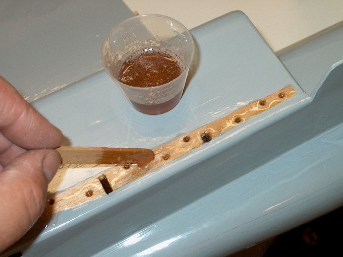
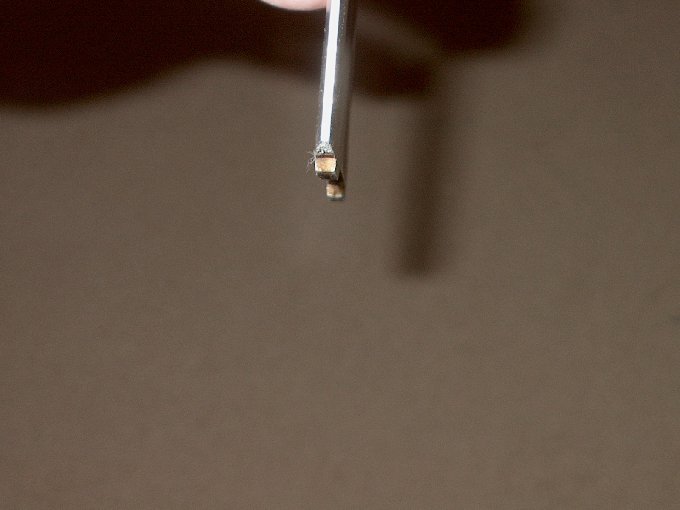
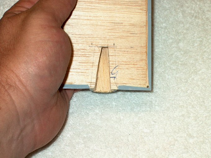
99 - Adding the washer and nut.
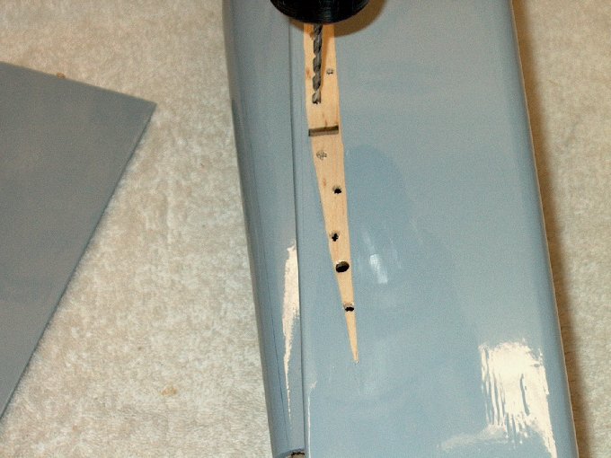
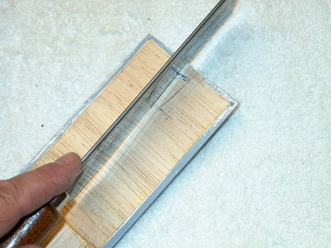
| |
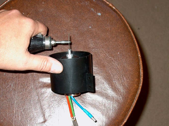
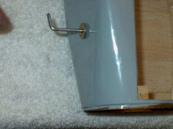
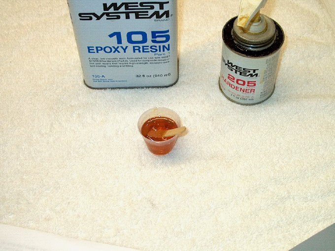
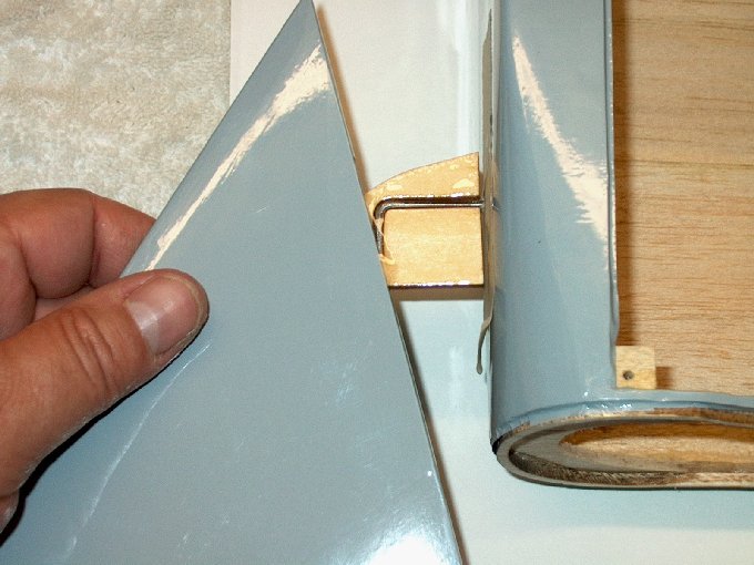
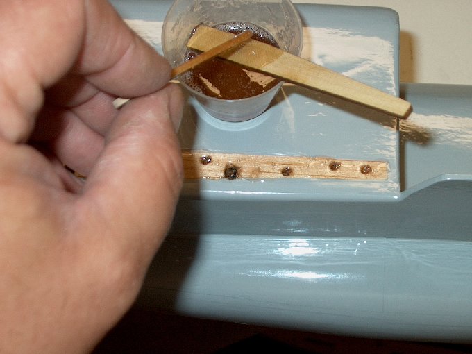
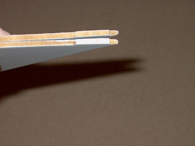
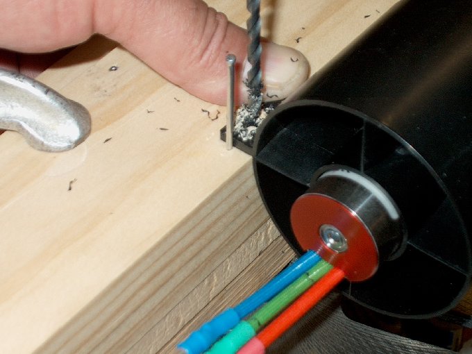
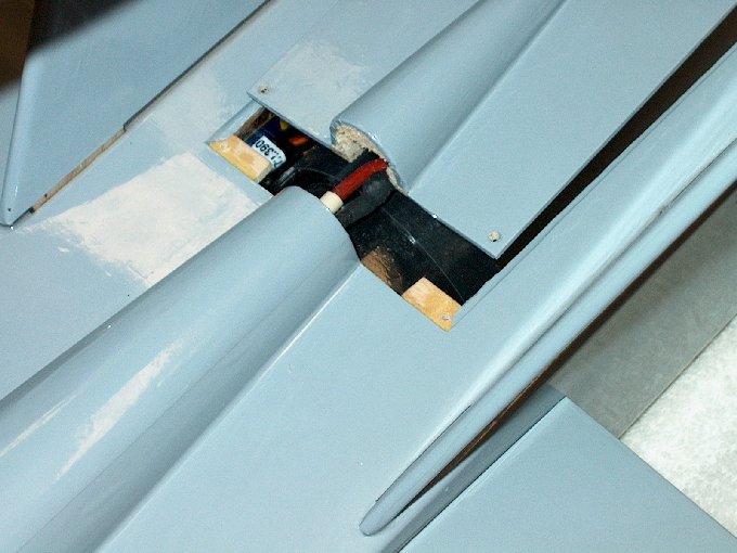
100 - Slotting the tip of the shaft so the
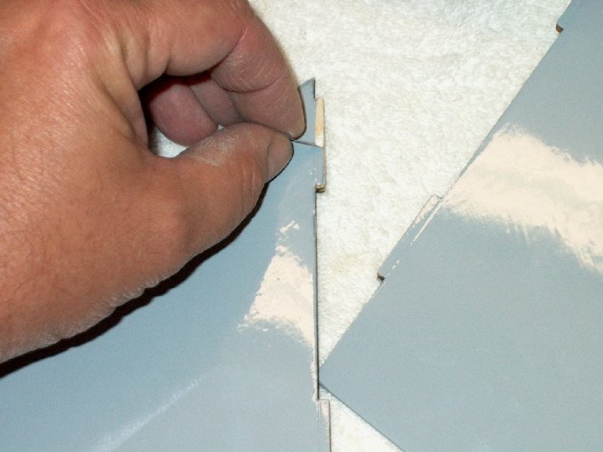
nut can be tightened. | |
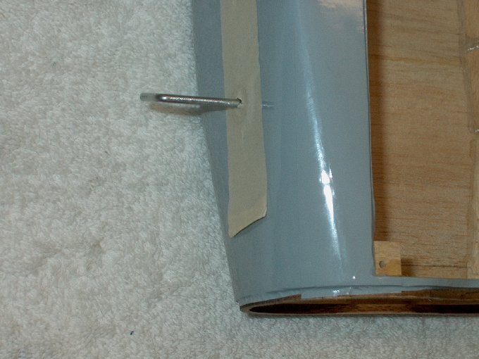
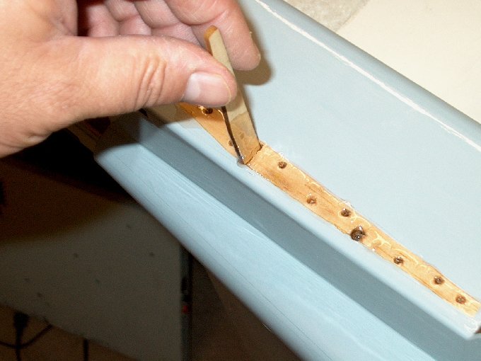
101 - Slotting finished.
| |
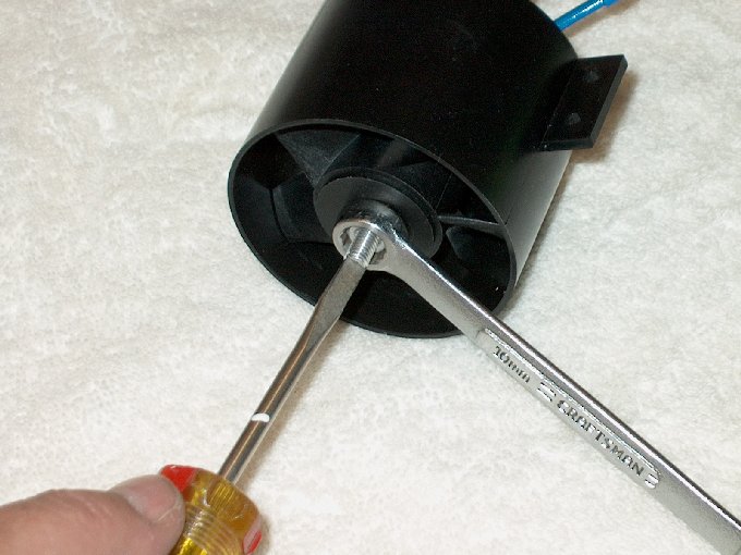
102 - A screwdriver can now hold the shaft
while it's tightened with a 10mm wrench.
| |
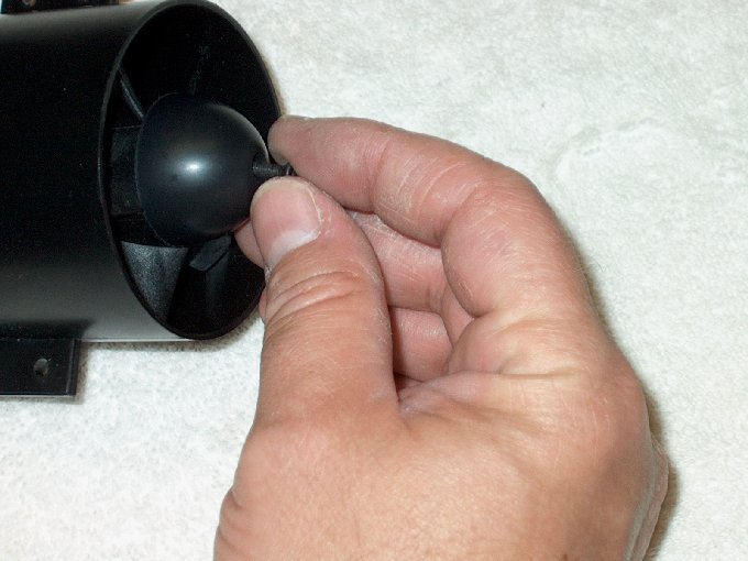
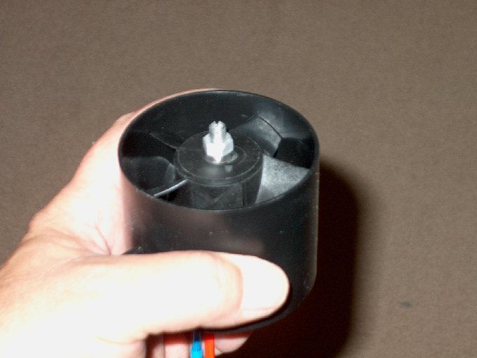
103 - Installing the cone.
| |
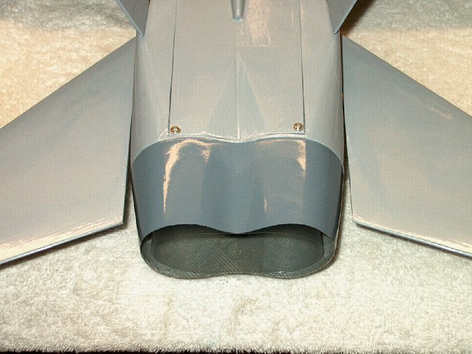
104 - Rear view of assembly.
| |
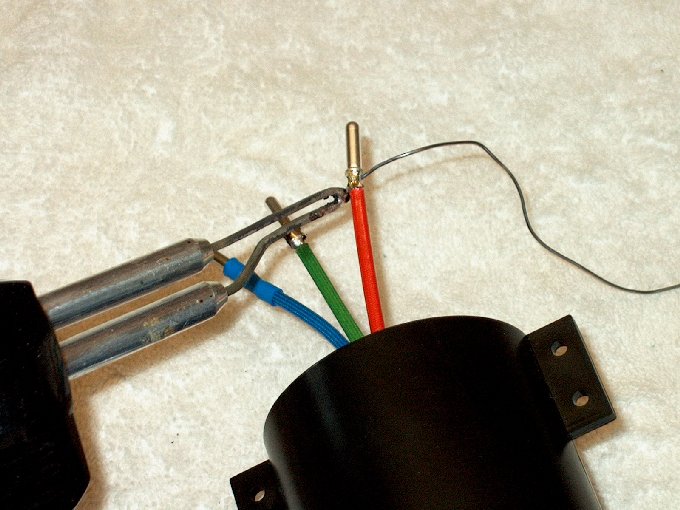
105 - Soldering the plug tips on the
motor. | |
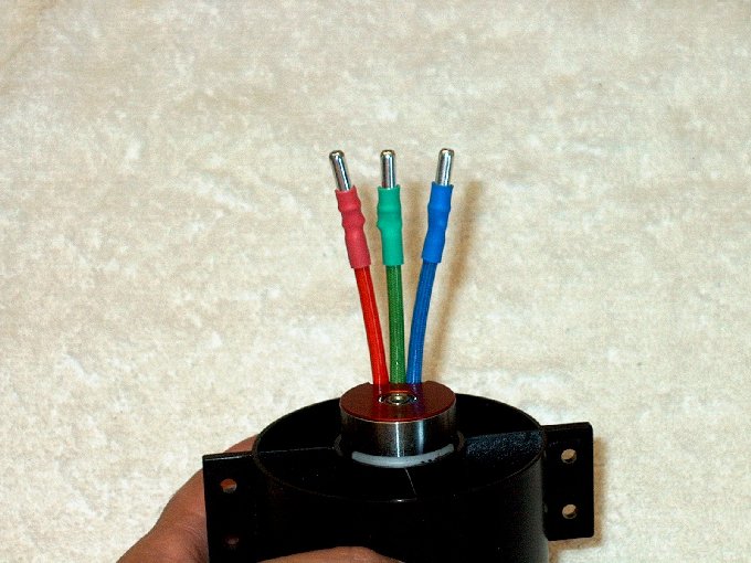
106 - Plugs installed.
| |
107 - Motor was connected to receiver and
battery to adjust balance. The cone was loosened and rotated
90 degrees at a time until minimal vibration was found while
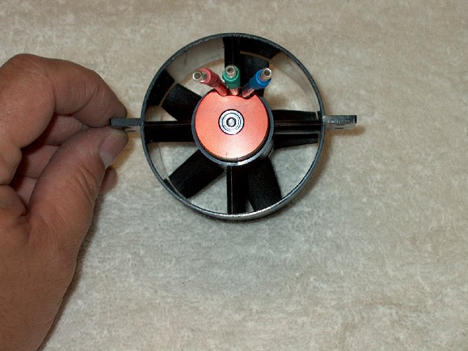
running. | |
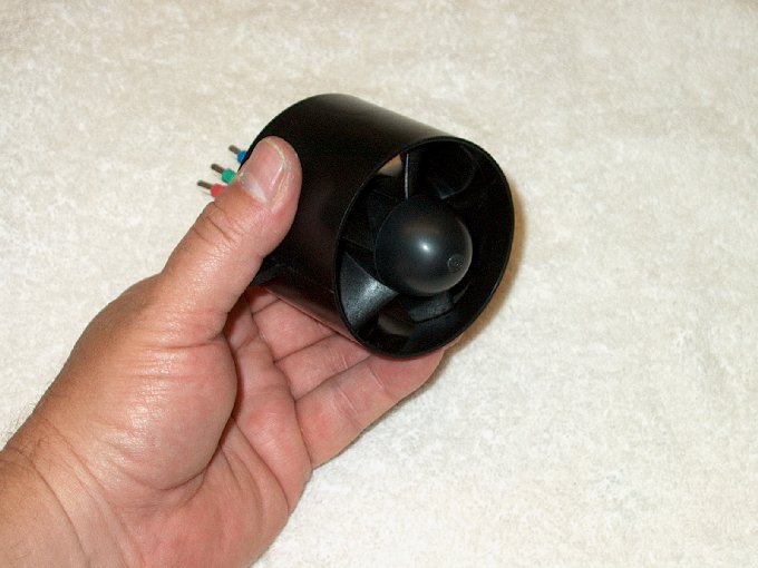
108 - Fan assembly balanced... ready to
install. | |
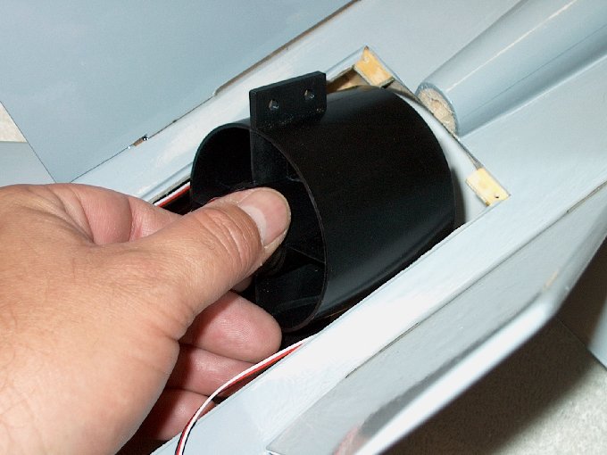
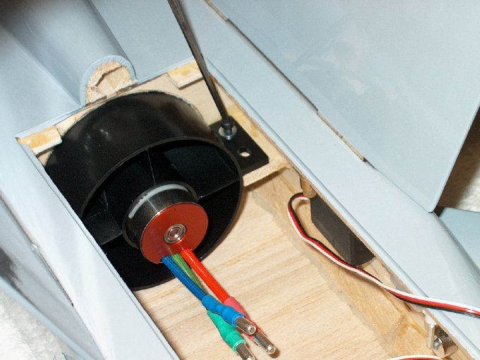
109 - Installing the fan.
| |
110 - The rear blind nuts for the mounting
bolts were installed in the jet 1/16" too far forward. The
rear mounting holes were lengthened to compensate.
| |
111 - Bolting the unit to the mounts.
| |
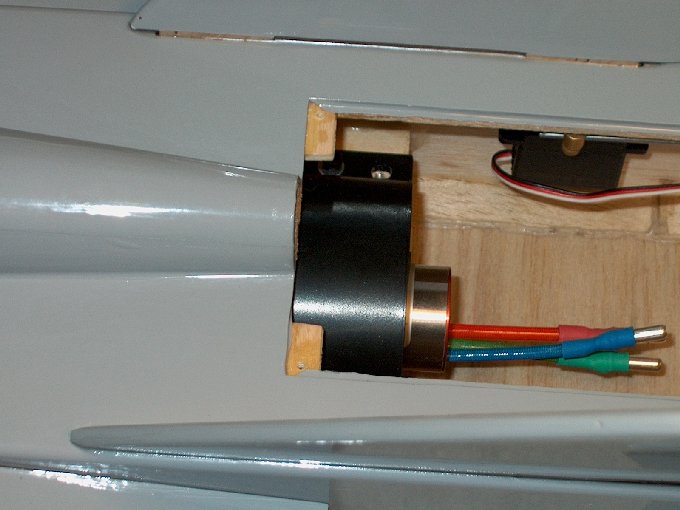
112 - You can see the rear (right) blind
nut and why the holes needed extending.
| |
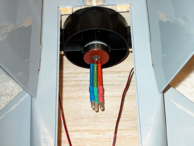
113 - Fan installed.
| |
114 - Double-thick double sided tape added
to bottom of receiver. | |
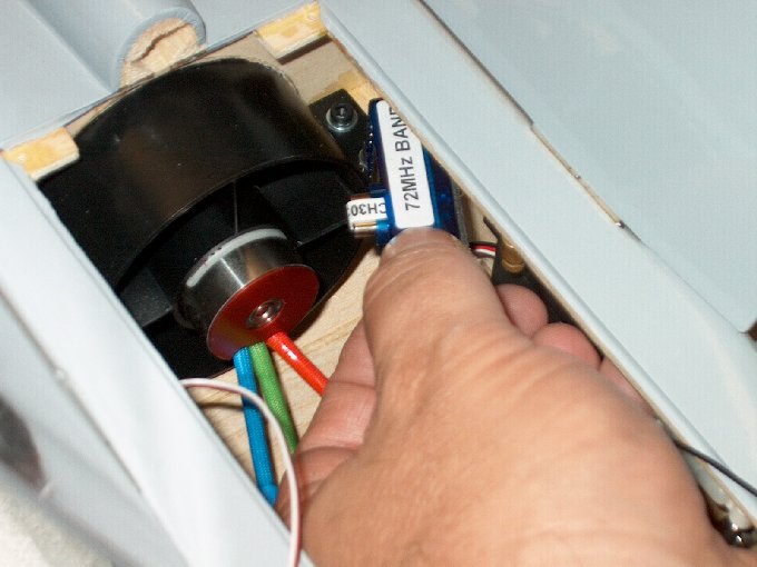
115 - Installing the receiver.
| |
116 - This was the best spot to place the
receiver. | |
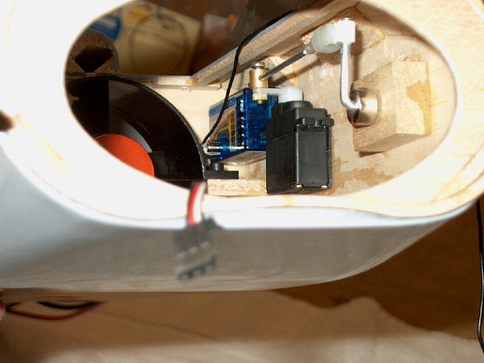
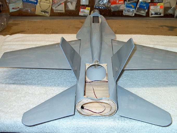
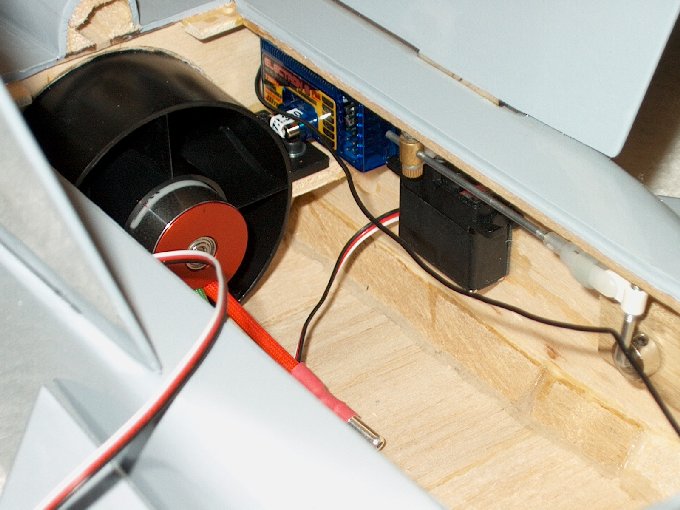
117 - A rear view showing components
position... it all just fits. | |
118 - Installing an antenna rod.
| |
119 -Rod being inserted into hole.
| |
120 - Rod installed...
| |
121 - Antenna run... I wanted to try this
position as it give a full run for the wire from the rear to
front. We will see how bad the power wires interfere and can
change it if necessary before flying.
| |
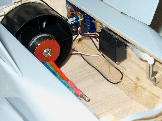
122 - Receiver wired.
| |
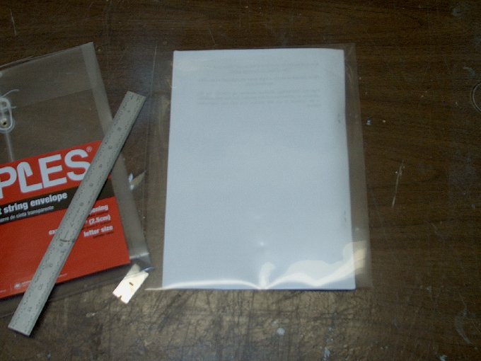
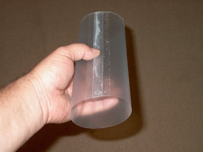
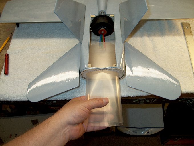
123 - Making a lighter and transparent
thrust tube. | |
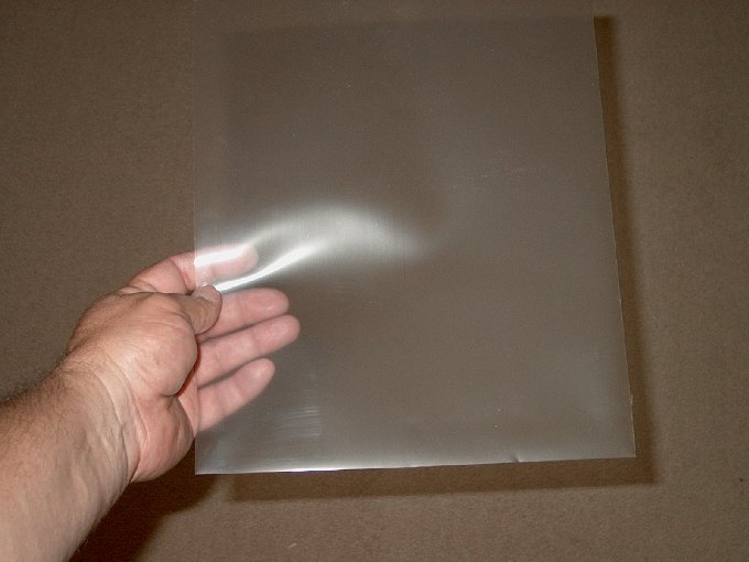
124 - Sheet cut from folder.
| |
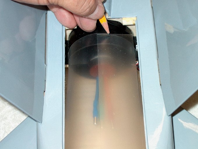
125 - Marking to trim.
| |
126 - Slots cut to clear fan mount... 3/8"
wide x 1/2" deep. | |
127 - End mark for trimming.
| |
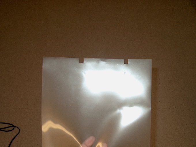
128 - Sheet cut to shape.
| |
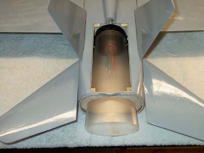
129 - Temporarily installed.
| |
130 - Seam taped on inside.
| |
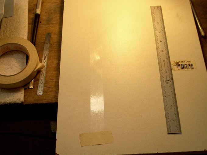
131 - Outside tape tacked to board, sticky
side up. | |
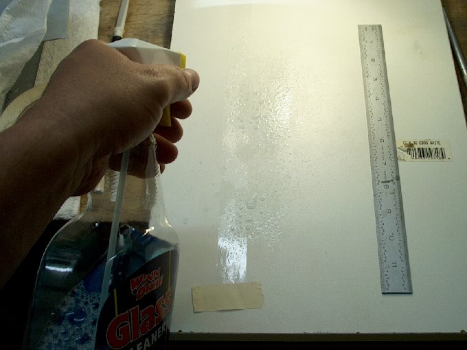
132 - Sprayed with Windex so it can be
"bubble free". | |
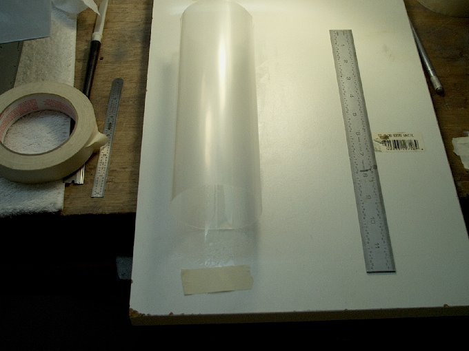
133 - Tube placed on tape.
| |
134 - Tube taped up, checked for
fit. | |
135 - Fits fine.
| |
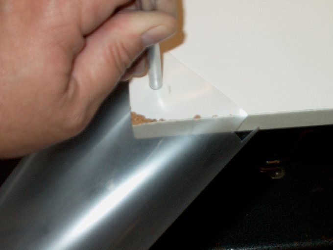
136 - Cutting a wire exit hole using a
piece of aluminum tubing. | |
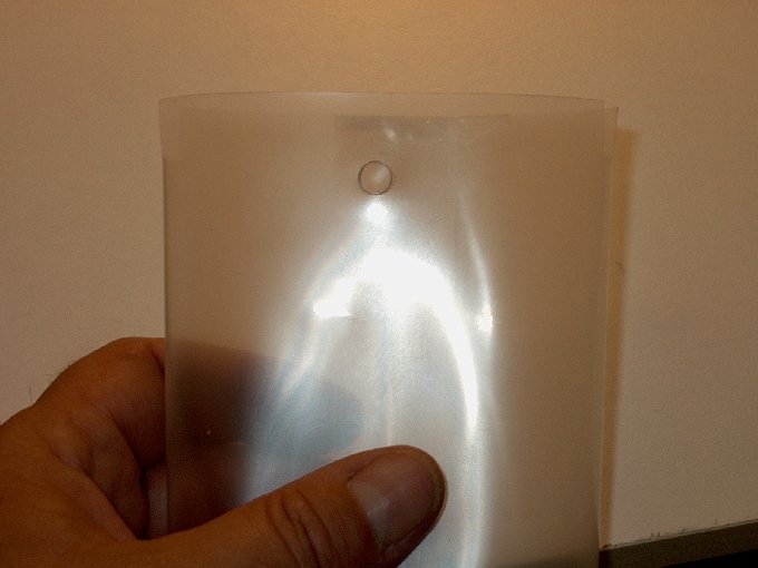
137 - Hole cut.
| |
138 - ESC plugged into motor. Leads heat
shrunk so they don't come loose. | |
139 - ESC bent forward with black power
wire and servo wire tie-wrapped to motor leads to hold them in
place. | |
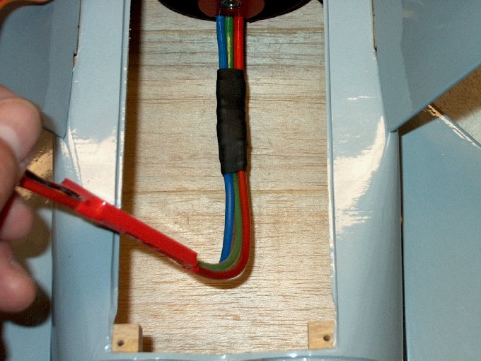
140 - Wires fed through top hole in thrust
tube. | |
141 - Thrust tube slid into place.
| |
142 - Servo wire fed towards
receiver. | |
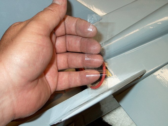
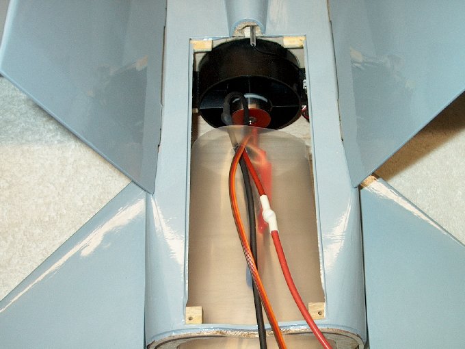
143 - Packing tape used to hold the thrust
tube on the fan housing. | |
144 - Tape installed.
| |
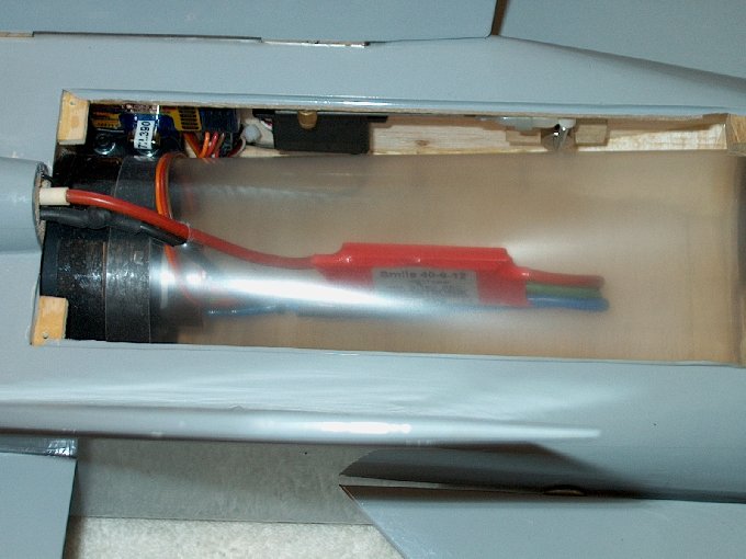
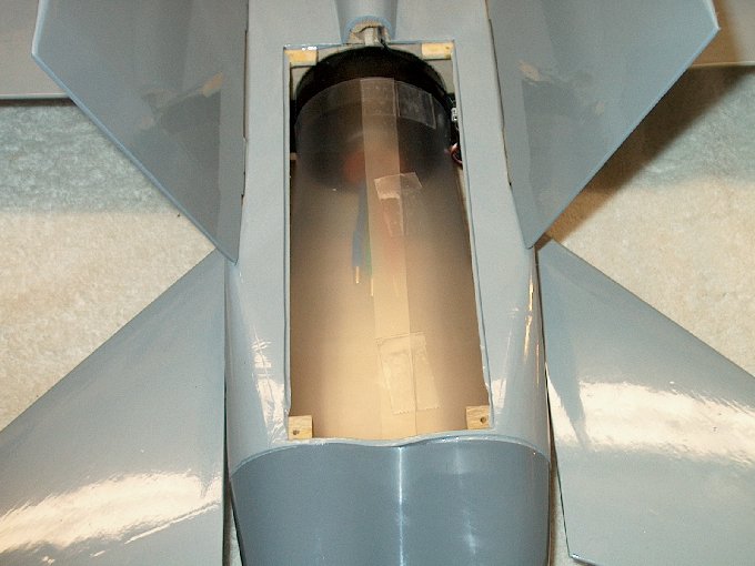
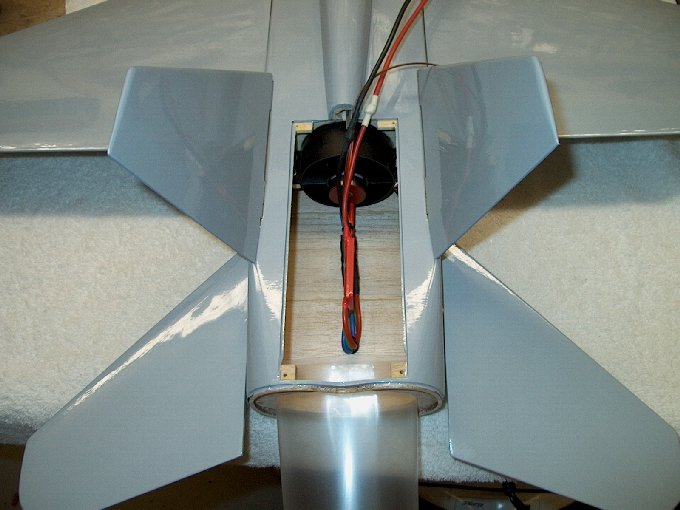
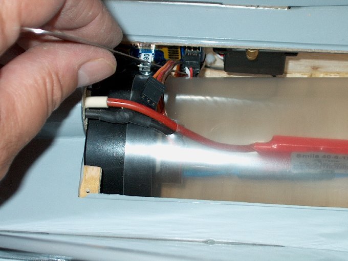
145 - View of simple wiring showing ESC
centered in thrust tube. | |
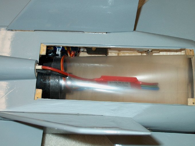
146 - Make sure th wires do not bingand
the ESC is centered | |
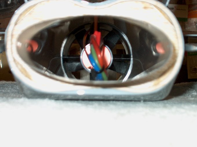
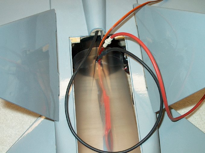
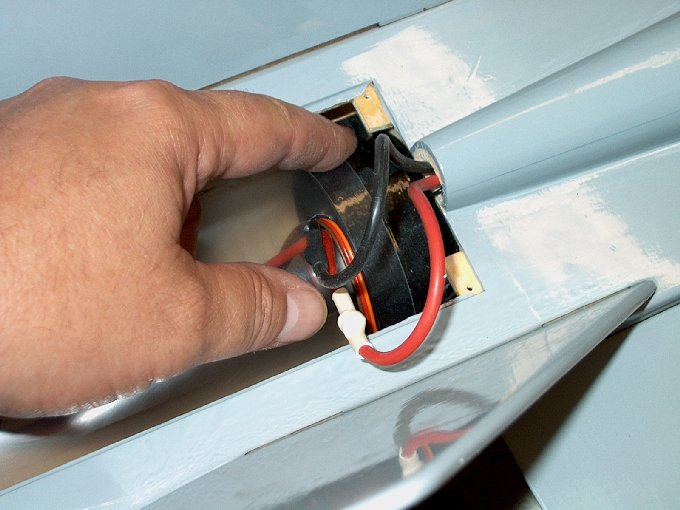
147 - Rear view shows centered ESC... note
wire tie at rear bend to keep wires from flying around under
thrust. | |
148 - Installing a battery connector...
Deans Ultra Plugs were used. | |
149 - Deans Ultra power plug
completed | |
150 - Battery installed.
| |
151 - Cutting a slot in the rear cover to
accommodate wiring. | |
152 - Opening cut.
| |
153 - Wires clear the hatch.
| |
154 - Rear access hatch installed.
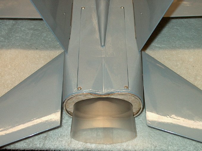
| |
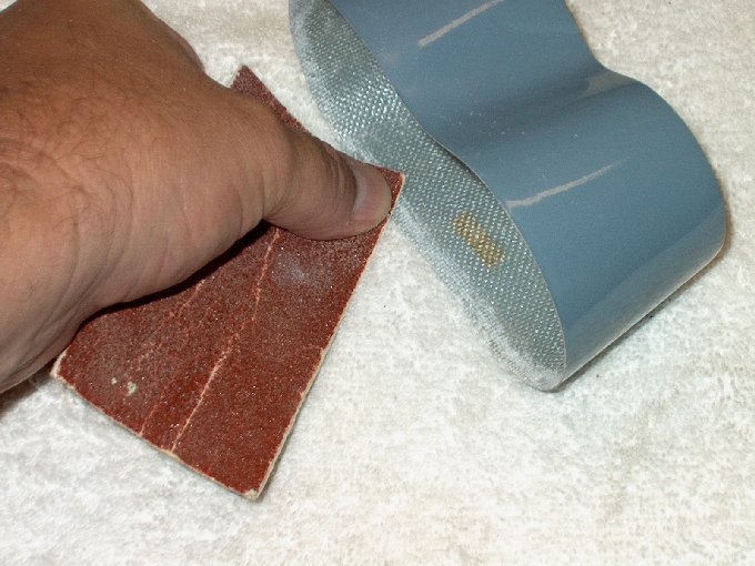
155 - Using 60 grit sandpaper to rough up
the inside. | |
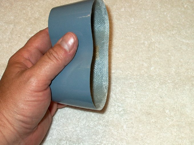
156 - Inside lip sanded.
| |
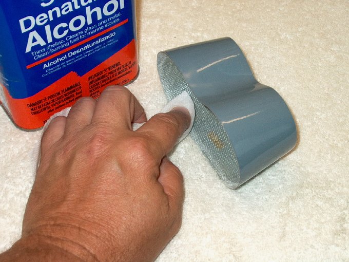
157 - Cleaning sanding dust with
alcohol. | |
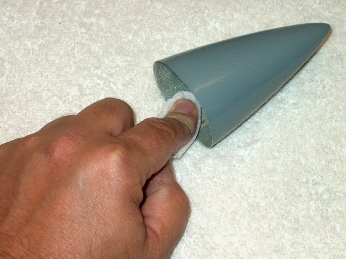
158 - Sanding the inside of the nose with
60 grit. | |
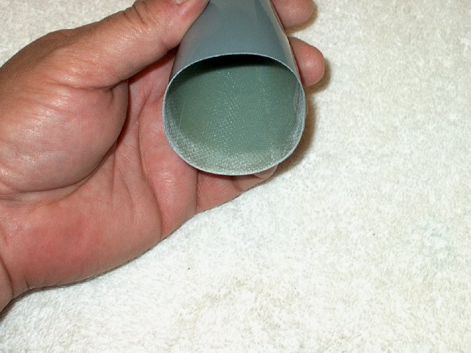
159 - Inside roughed up.
| |
160 -Dust removed with towel and alcohol.
| |
161 - Epoxy applied to the rear, I used
epoxy because it is more compatible with the glass tail, which
is made from a epoxy / glass mix. | |
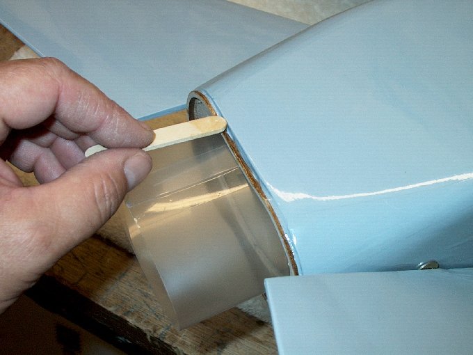
162 - Applying a line of epoxy to the
inside of the tail. | |
163 - Tail pressed into position.
| |
164 - ... and excess epoxy removed with
alcohol and a towel. | |
165 - Masking tape used to hold it in
place while the epoxy sets. I used 15 minute epoxy to allow it
to soak into the wood. | |
166 - Model positioned upright to allow
any remaining epoxy inside to flow down and create a fillet.
| |
167 - Tail installed.
| |
168 - Applying epoxy to the nose area.
| |
169 - Epoxy applied to the inside of the
nose. | |
170 - Nose pressed in place.
| |
171 - Excess epoxy cleaned up with paper
towel and denatured alcohol. | |
172 - Nosecone installed.
| |
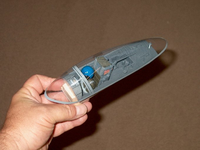
173 - The cockpit and canopy.
| |
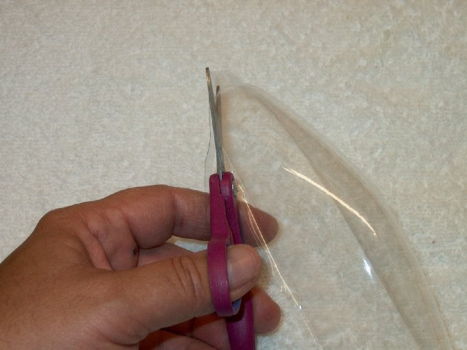
174 - First, I cut the bottom lip away
from the canopy. | |
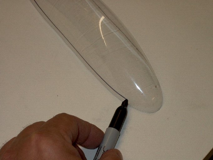
175 - Next, I used a permanent marker and
holding it flat on the table, it nearly "self-drew" a line all
the way around. | |
176 - The front of the canopy has a sharp
angle about 1/2" long and up from the bottom... the top curved
line was drawn right at the point where this curve goes
shallow. You want to get rid of the large hump.
| |
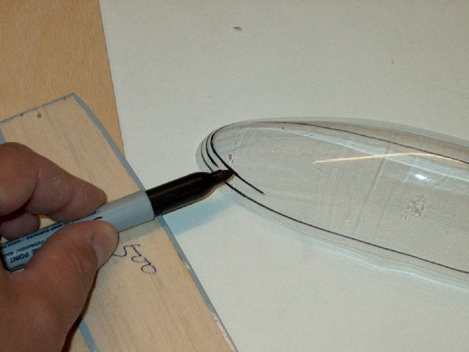
177 - You can see the angle of the front
better here... the upper mark will be the cut line.
| |
178 - Examining the canopy.
| |
179 - The front edge was angled downward
to where the canopy meets the dash. I did this by centering it
front to back over the model and making marks on the sides.
| |
180 - You can see that the mark for the
front is 2" from the tip. | |
181 - Canopy cut at an angle from this
mark to the bottom edge of the rear.
| |
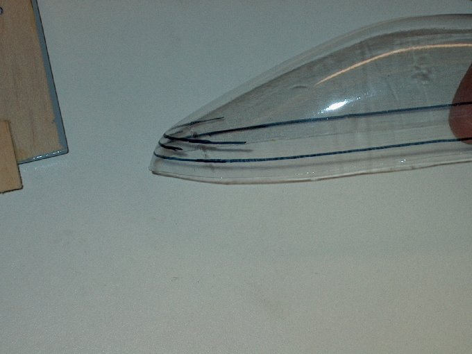
182 - You can see it where it was cut...
the remaining excess and hump area in the rear will be removed
at the line. | |
183 - Cutting it out at the rear on the
original line, which was drawn in the early steps and is about
1/4" from the bottom. | |
184 - This is how much hump that was
removed from the front of the canopy.
| |
185 - Fitting the canopy.
| |
186 - Nice fit with no humps.
| |
187 - Although it was permanent marker,
the lines easily wipe away with denatured alcohol.
| |
188 - Cleaned up canopy.
| |
189 - Canopy in place.
| |
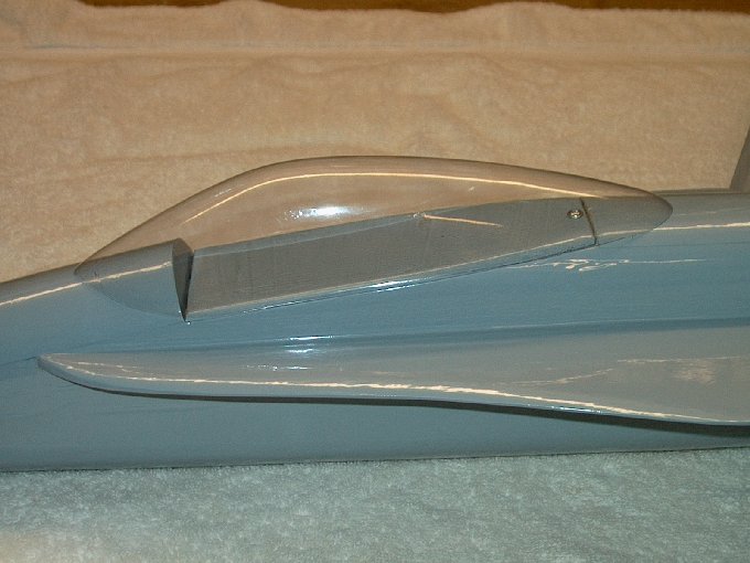
190 - Side view of canopy.
| |
191 - Time to adjust throws... ruler taped
to table top works. | |
192 - 1/2" down elevator.
| |
193 - 1/2" up elevator.
| |
194 - Time for ailerons.
| |
195 - 1" right aileron.
| |
196 - 1" left aileron... adjustments are
done... I set dual rates at 3/8" elevator and 5/8" aileron,
but will adjust after the first flight.
| |
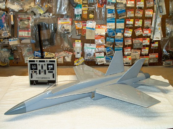
197 - FA-18 built, radio adjusted and
ready for decals. | |
198 - Building a custom cockpit fro balsa
and thin ply. | |
199 - Edging using the balsa.
| |
200 - Bottom plate.
| |
201 - Installed plate.
| |
202 - Adding rivets.
| |
203 - Larger view.
| |
204 - Rivets about finished.
| |
205 - Pilot initially painted.
| |
206 - Seat made from balsa and real cloth
chute bag. | |
207 - Shaping the new cockpit to the
model, which was protected by masking tape.
| |
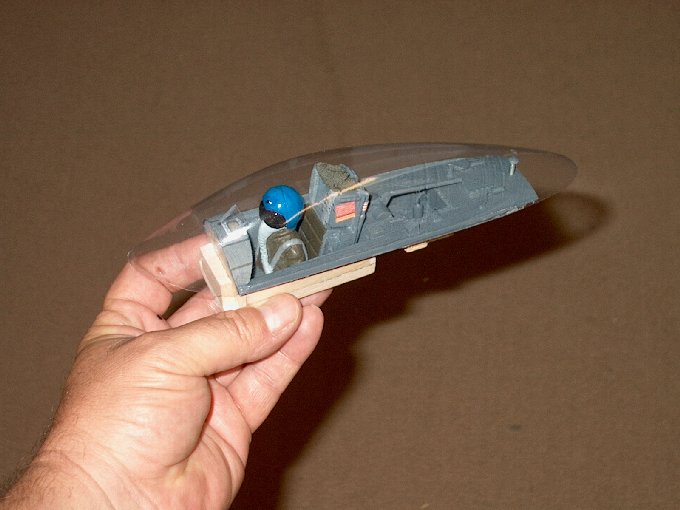
208 - Final fit checked.
| |
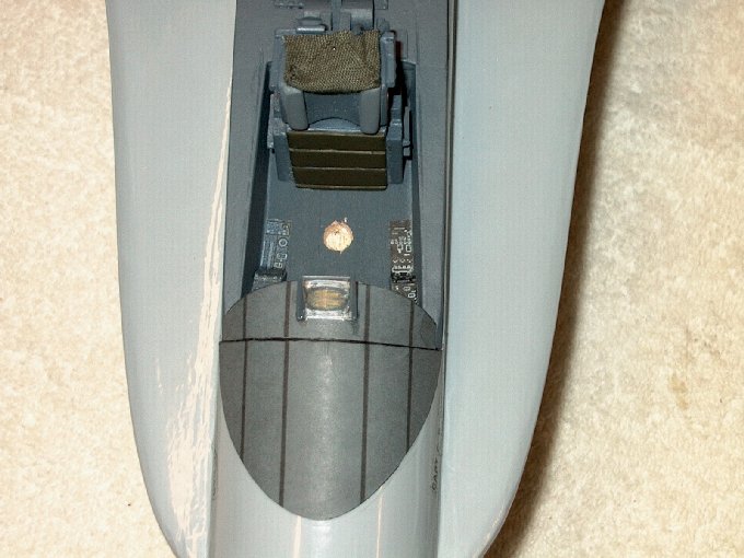
209 - Cockpit finished.
| |
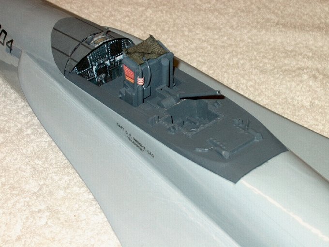
210 - Small details added.
| |
211 - Adding the instrument panel hood.
| |
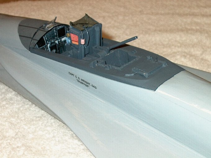
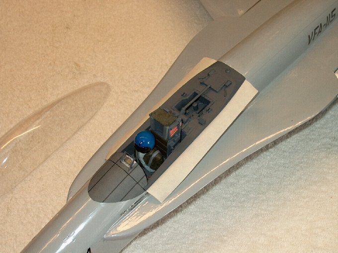
212 - Instrument panel and labels
installed, cockpit detail finished.
| |
213 - Another view, it was modeled after.
| |
214 - This is a photo I had of a bug
cockpit. | |
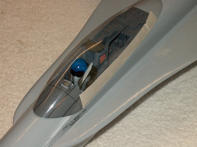
215 - Side view.
| |
216 - Front view with pilot temporarily
installed. | |
217 - Glass still needs lines painted, but
a quick look. | |
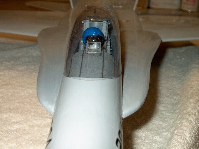
218 - This guy's ready to taxi!
| |
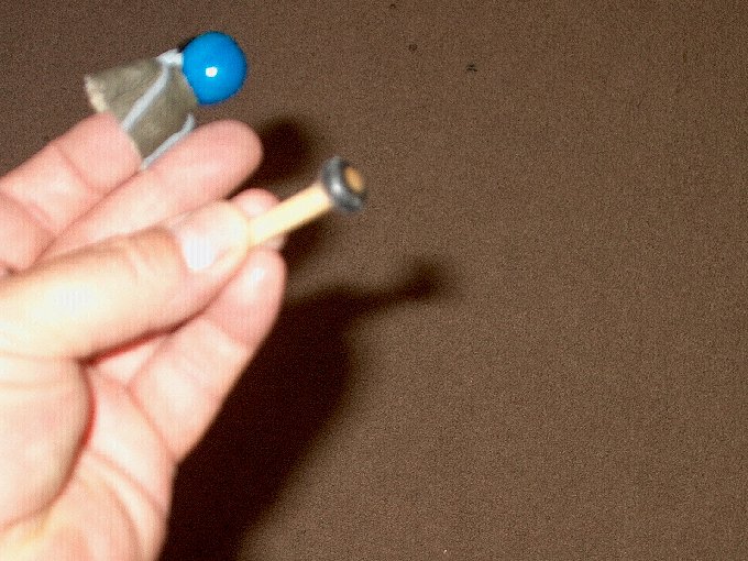
219 - Installing the pilot... I epoxied a
rubber grommet on top of a 1/4" wood dowel.
| |
220 - Next, I pressed the dowel into the
head area of the pilot. | |
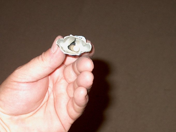
221 - A 1/4" hole was drilled into the
cockpit floor and epoxy was applied
| |
222 - Squeezing the figure to hold the
dowel, it was placed in the hole until the pilot base was
seated against the floor and left to set up. You can either
epoxy the pilot to the dowel/grommet, or leave it dry to
change it out for a different pilot for variety.
| |
223 - RC56 glue added and masking used to
hold cockpit in place until dry. | |
224 - Taping it up this way allowed the
cockpit to be removed while the glue set.
| |
225 - Canopy glue set up and tape was
removed. | |
226 - Working on panel lines for the
Bug... about half done and using a combo of photos and plastic
models for the locations. | |
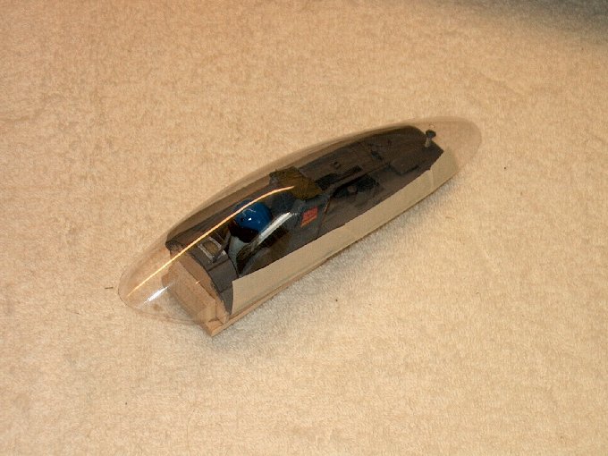
227 - Canopy masked for paint.
| |
228 - Canopy painting completed.
| |
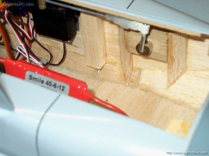
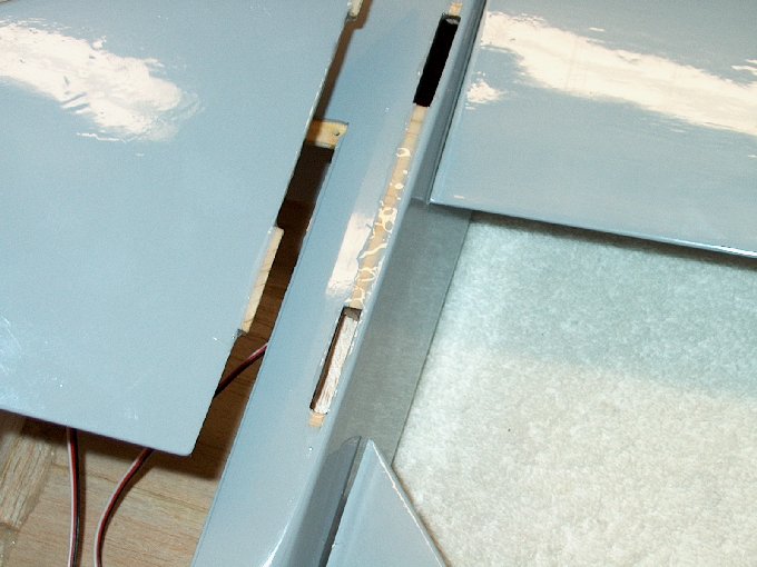
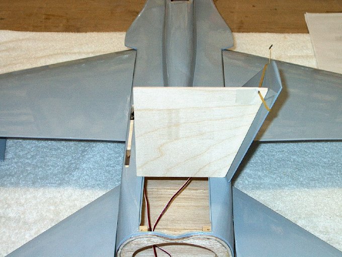
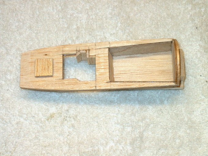
229 - This is a recommended MOD for the
FA-18. Balsa supports are glued from top to bottom on both
sides of each servo and taileron block as shown
| |
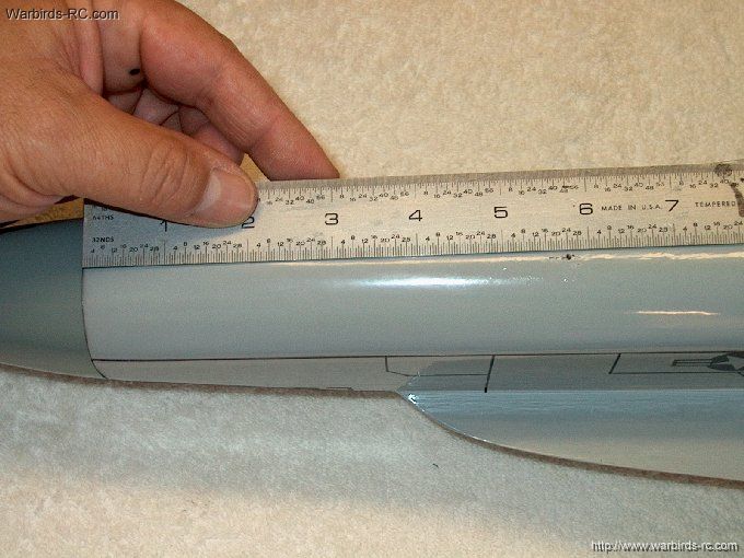
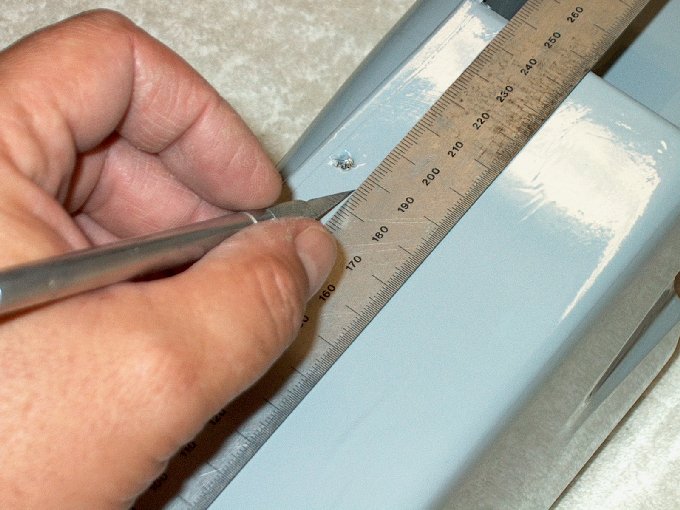
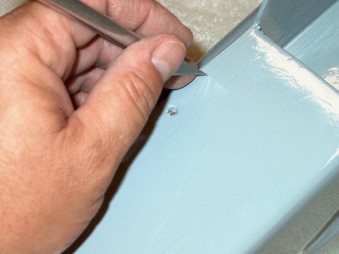
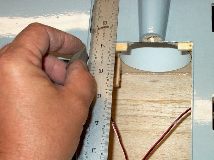
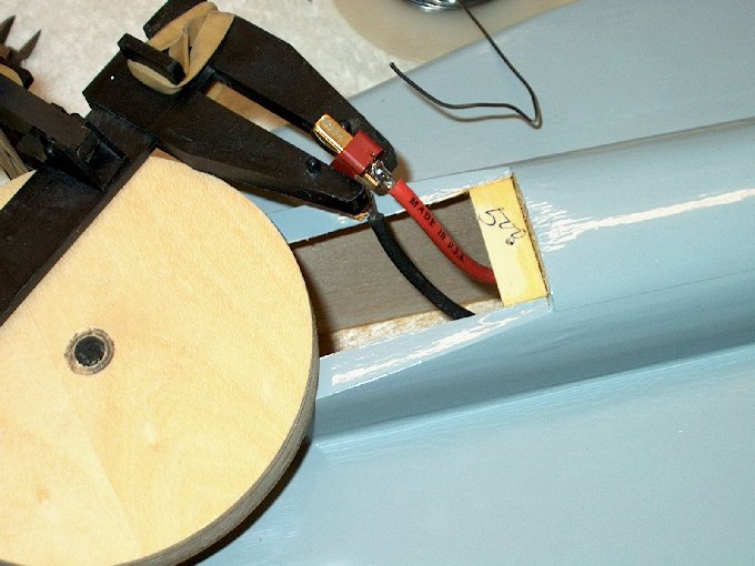
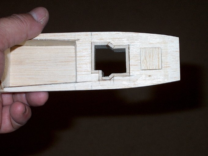
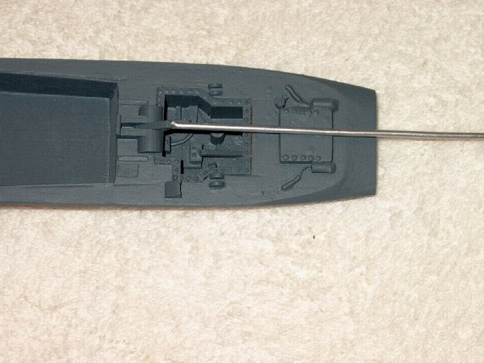
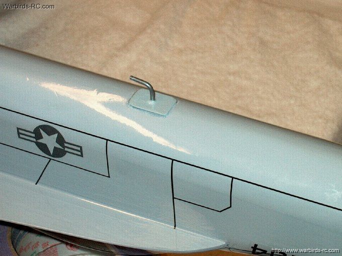
230 - The hole for the towhook is hard to
find under the cover, but it is located 5 3/4" from the back
of hte nosecone | |
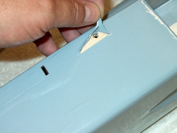
231 - While you can glue the towhook
directly in the fuselage, I cut a larger opening to reinforce
the bottom of the fuselage | |
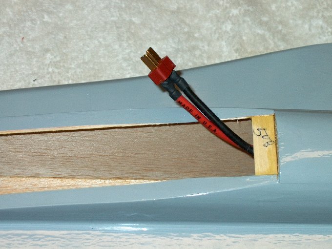
232 - The area is lightly sanded
| |
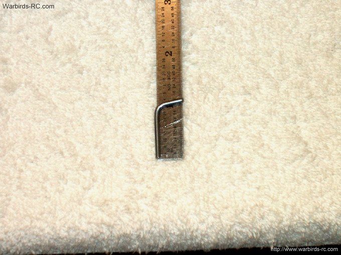
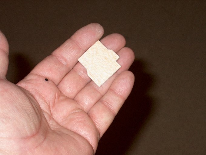
233 - The towhook is shaped as shown, with
a slight down angle on it as shown at the top
| |
234 - The long side that enters the
fuselage is roughed up with 60 grit sandpaper
| |
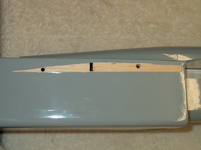
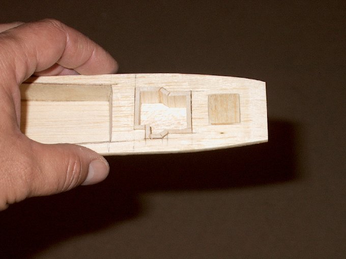
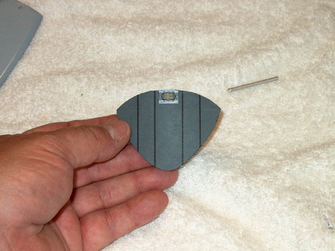
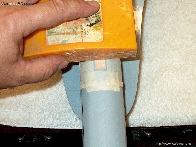
235 - Apply epoxy to the hole and hook,
then install it in place, followed by the small 1/32" thick
ply plate that was made. Teh tape is used to protect the
covering from excess epoxy | |
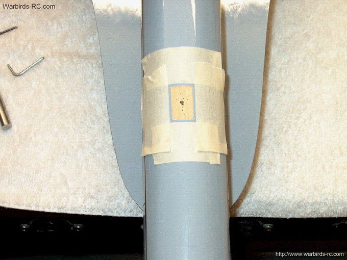
236 - Tape the plate in place and make
sure the hook is pointing straight back before the epoxy
sets | |
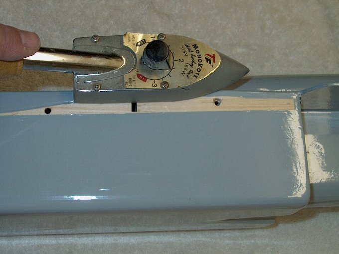
237 - Remove the protective tape and seal
the edges of the ply plate with CA | |
238 - The plate is painted to match the
fuselage. This prevents the bottom of the fuselage around the
hook from damage caused by heavy use
| |
239 - Side view of the hook in place.
| |
240 - Check CG, which is located 2 3/4"
from the inside tip of the wing | |
241 - Side view showing walk area in
black. | |
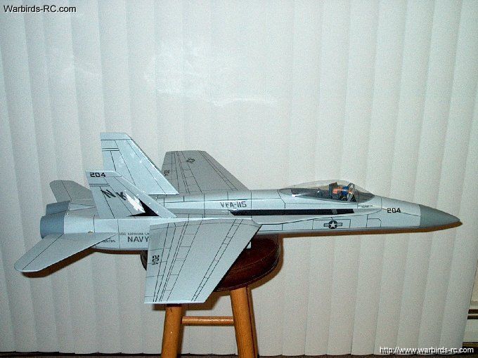
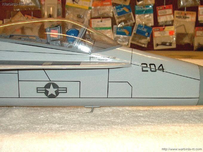
242 - Right Side View
| |
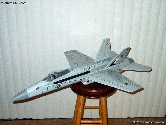
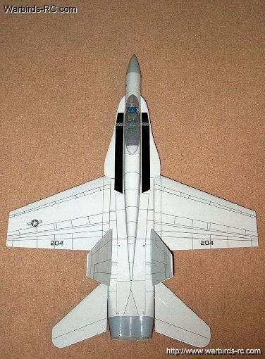
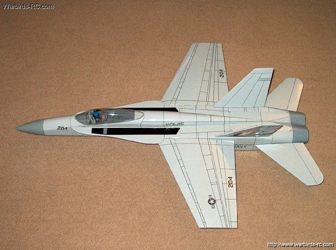
243 - The HET-RC FA-18 Hornet EDF Jet
| |

This Website and all documents herin are Copyright © 2012 www.scalerocketry.com -
All rights reserved.
| |