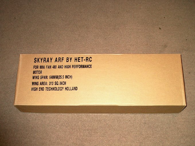
01 - Here's the box...
| |
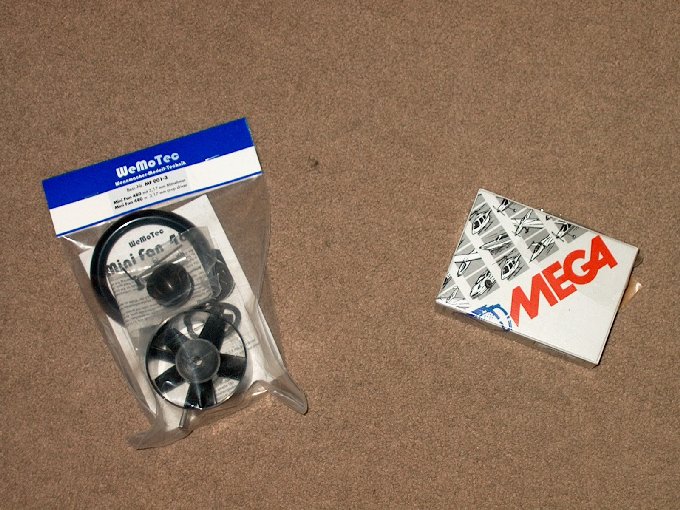
02 - ... and a couple items I ordered to
make the model fly. | |
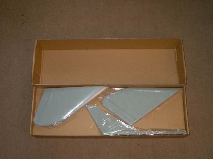
03 - Opening the box reveals typical
HET-RC packing, with wings taped inside to prevent damage from
movement. Take your time and carefully pull off all the tape
before removing the components. This will prevent damage that
can be caused if you use a knife. | |
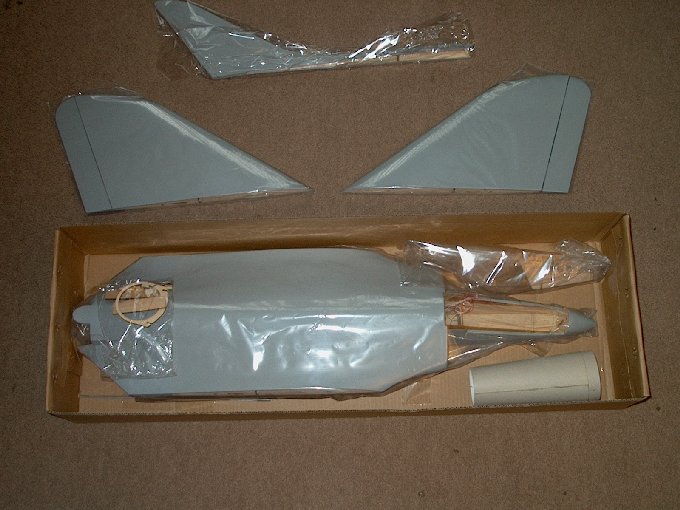
04 - Wings were removed from the inside
panel then the panel was lifted, revealing the airframe, parts
bag, cockpit assembly and thrust tube.
| |
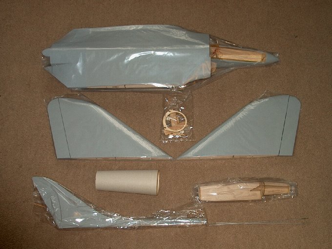
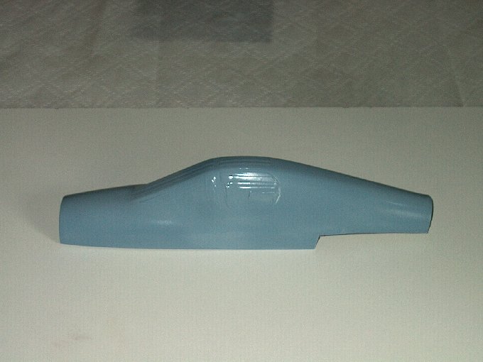
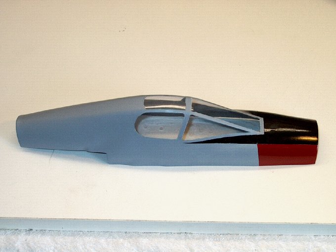
05 - The "F4D Skyray ARF"... this is how
it comes. | |
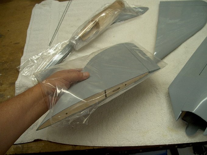
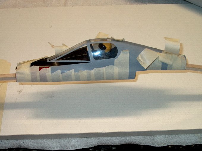
06 - Tape was carefully and completely
pulled off of each bag and then each item was removed. Pulling
off all the tape first makes sure a piece doesn't accidentally
stick to the covering and damage it.
| |
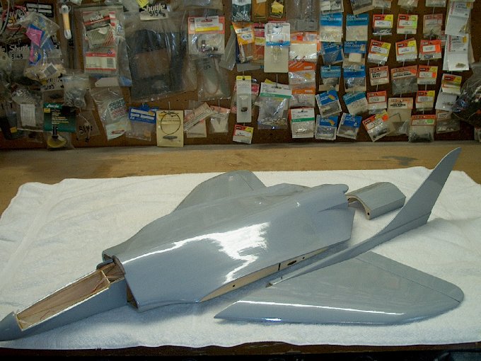
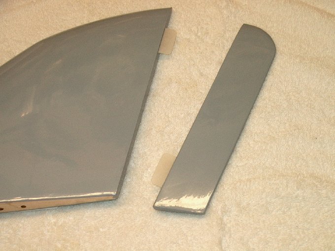
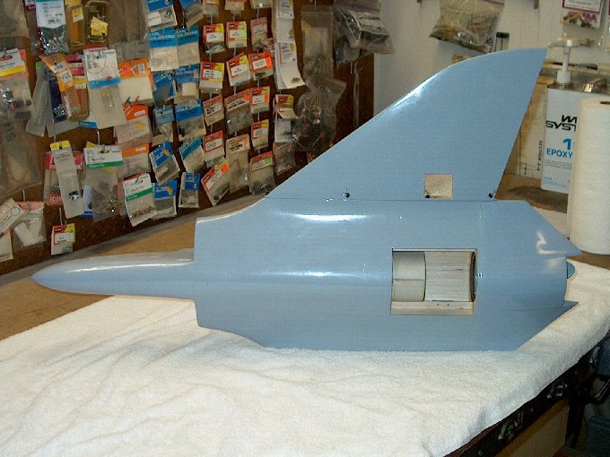
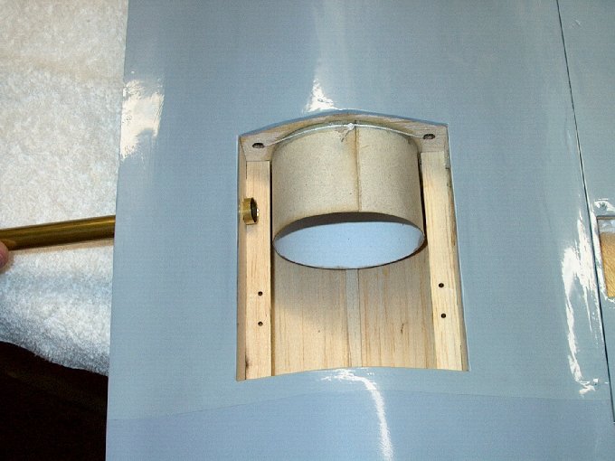
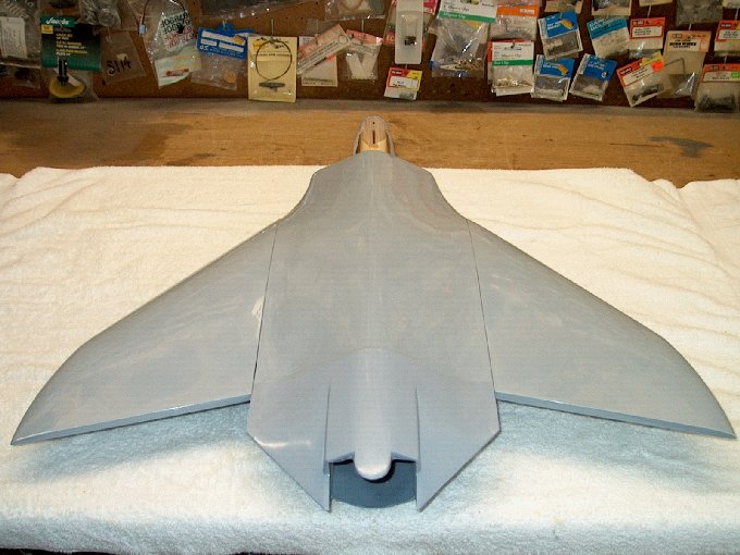
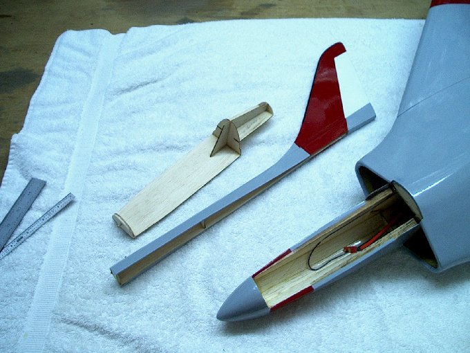
07 - The major components... top quality
craftsmanship and covering! | |
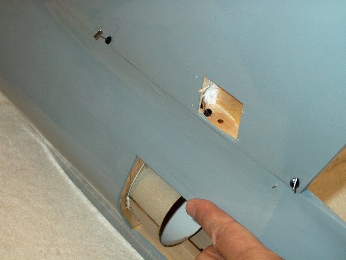
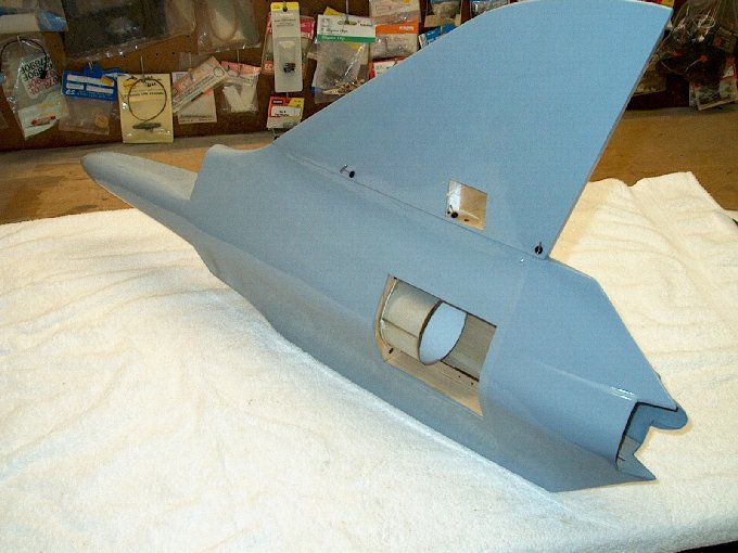
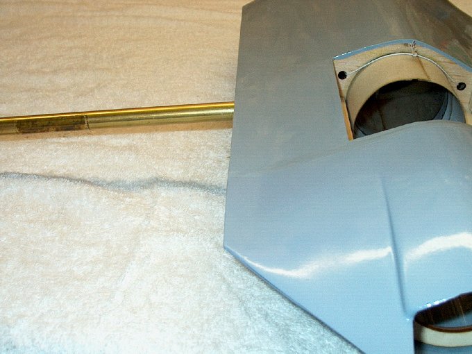
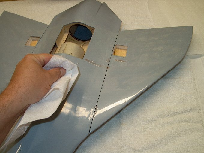
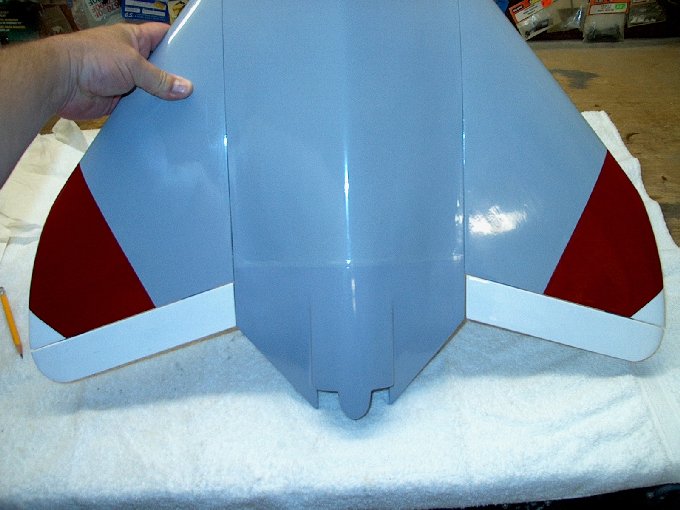
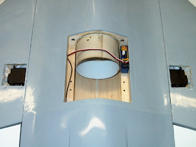
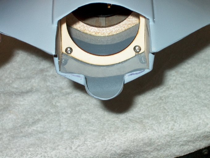
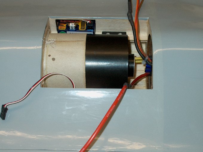
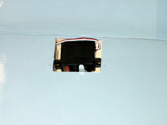
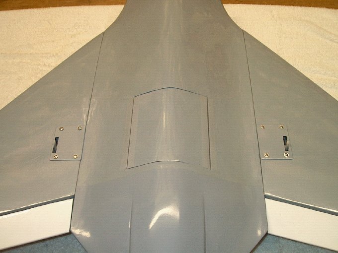
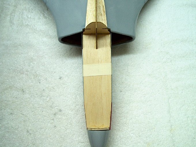
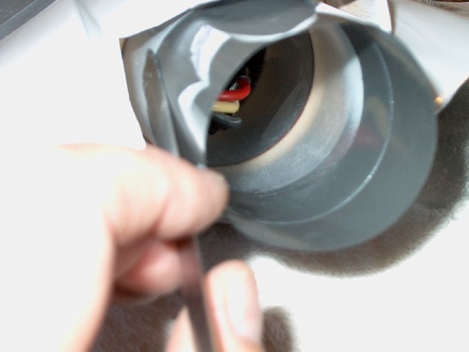
08 - The fan compartment is viewed from
below. | |
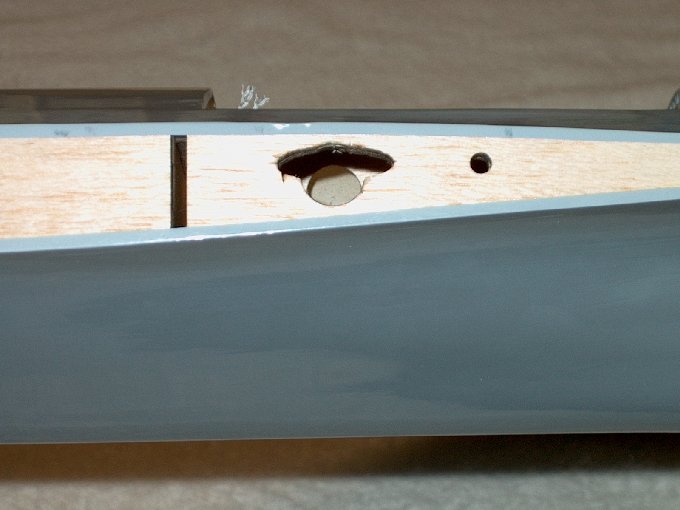
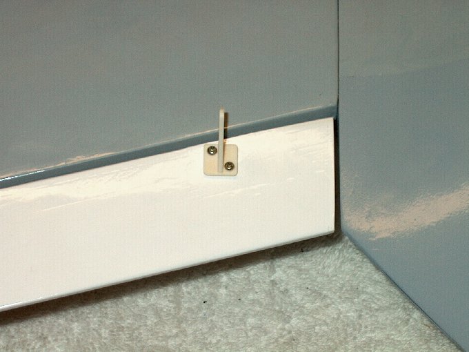
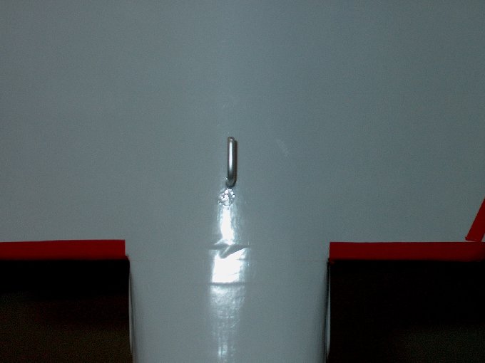
09 - HET-RC listened to their customers...
this tow hook location is easy to find!
| |
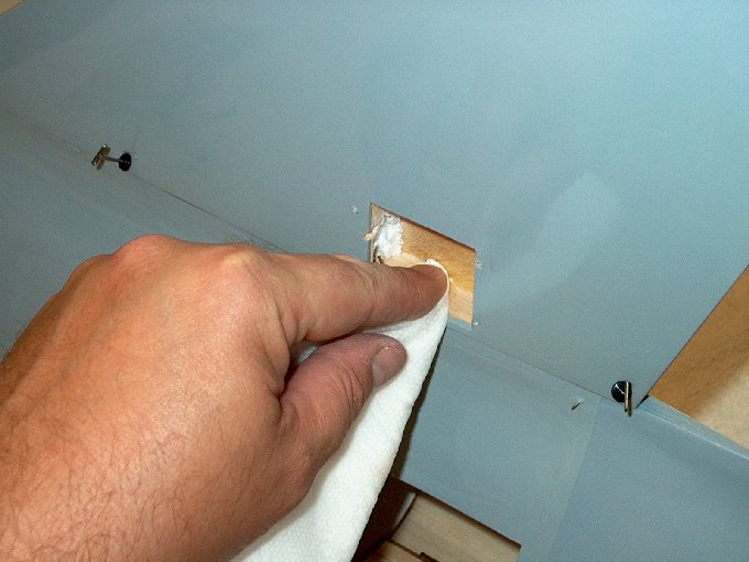
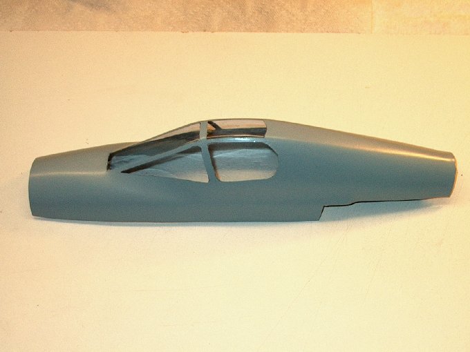
10 - The cockpit assembly. Once again,
improvements were found as the canopy has trim lines well
marked in the molding. | |
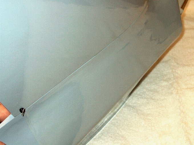
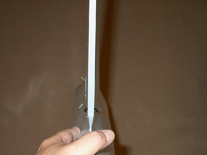
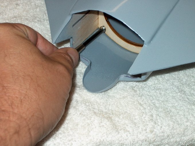
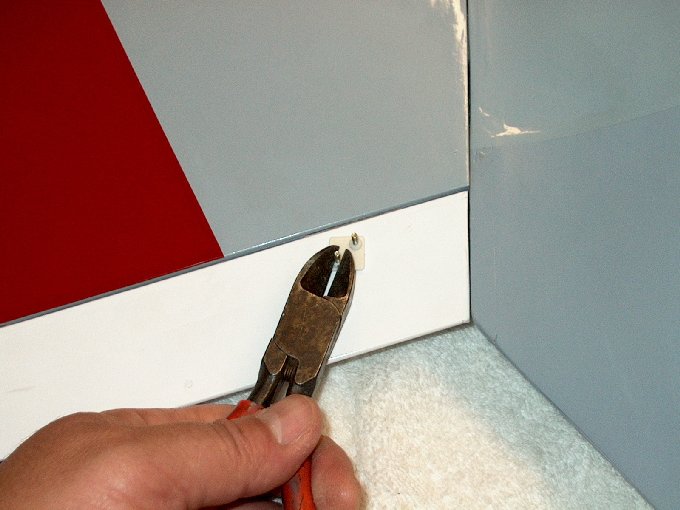
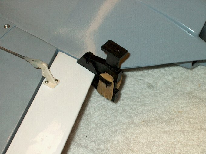
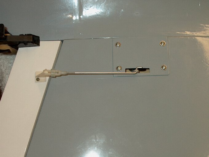
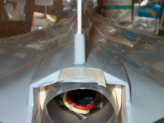
11 - The front of the vertical stab had a
small rod protruding. | |
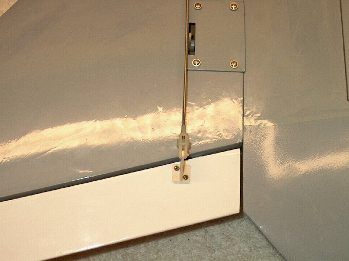
12 - A view underneath reveals this is a
rear canopy latch... a nice touch! | |
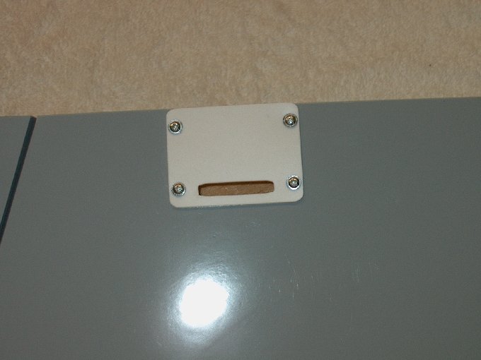
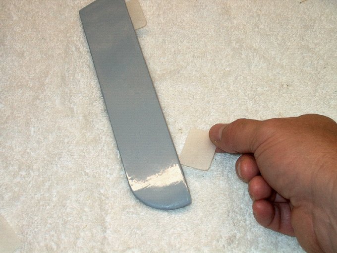
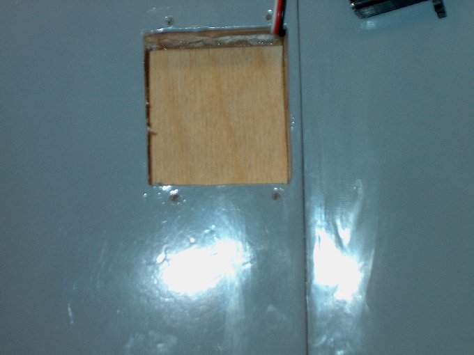
13 - Elevon servo covers are extra thick,
heavy duty plastic. | |
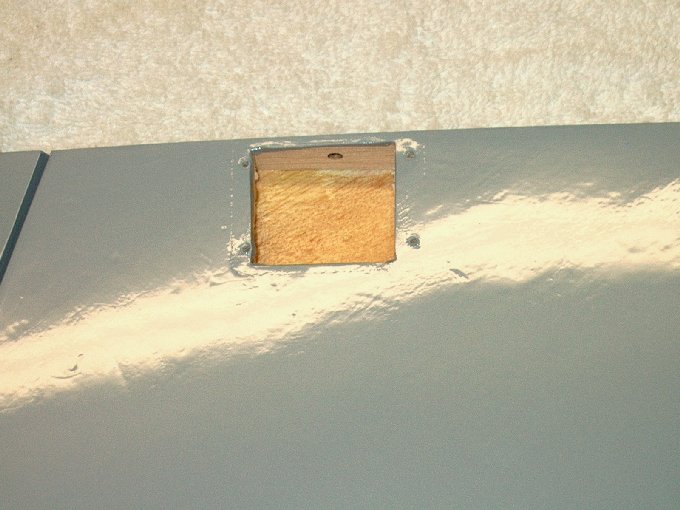
14 - Removing the cover reveals the servo
compartment. | |
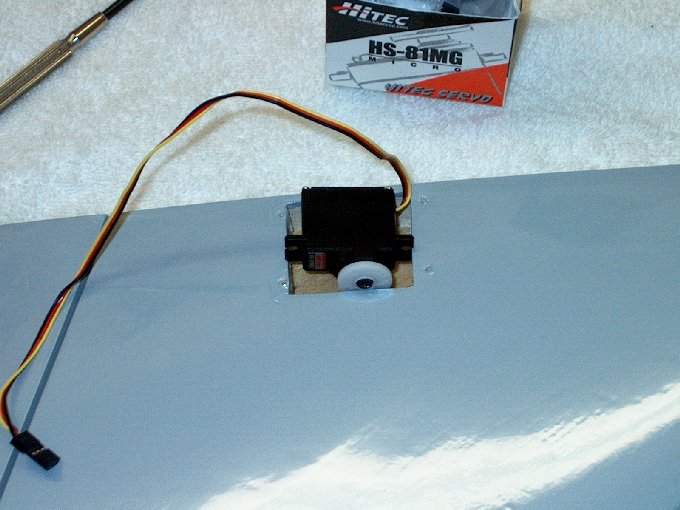
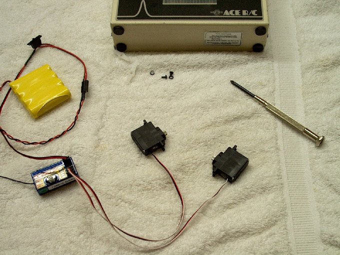
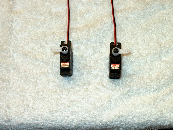
15 - My Hitec HS-81MG Metal Gear servos
will fit, but need a bit of coaxing.
| |
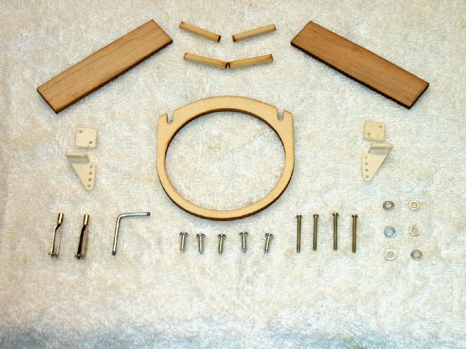
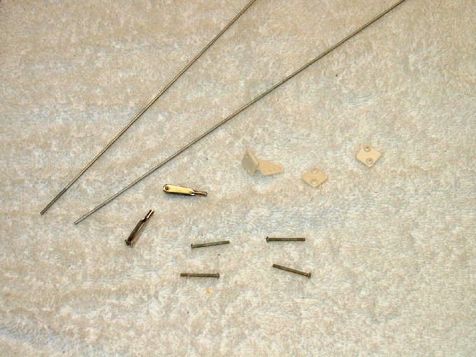
16 - The "bag" of components.
| |
17 - Control surfaces have heavy duty
hinges... they are removed before mounting the wing panels.
| |
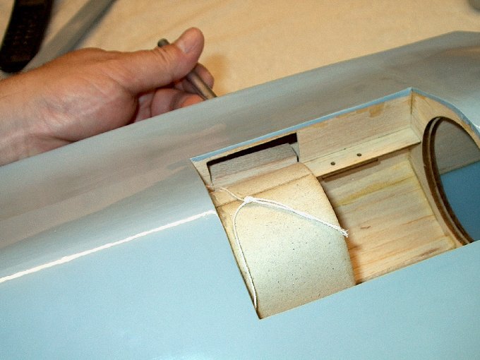
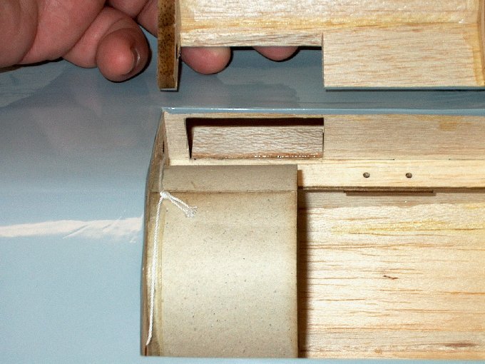
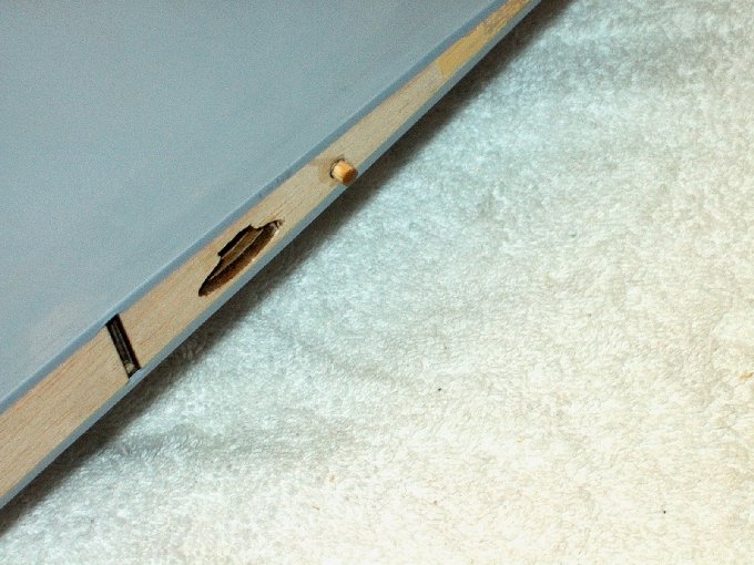
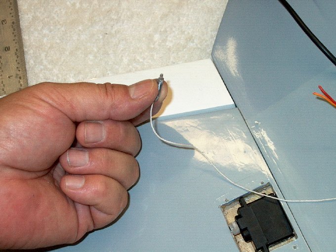
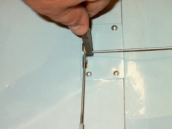
18 - A small slot was extended to remove
the wire pulling thread. | |
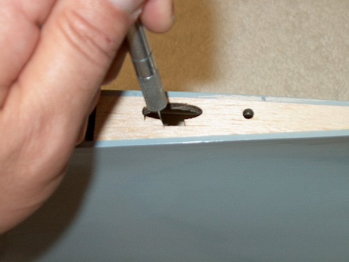
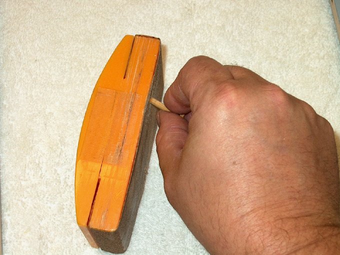
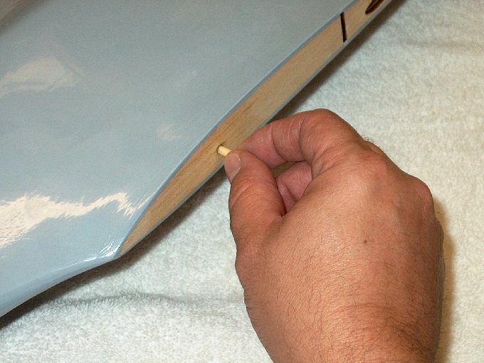
19 - The 1/4" stick has to be
pulled/snapped loose from inside as it is tack-glued in place
during shipment. Once loose, remove it through the enlarged
slot. | |
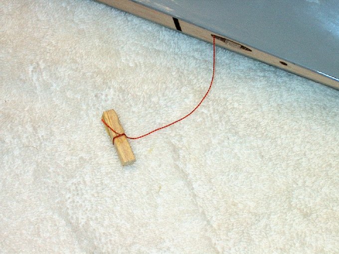
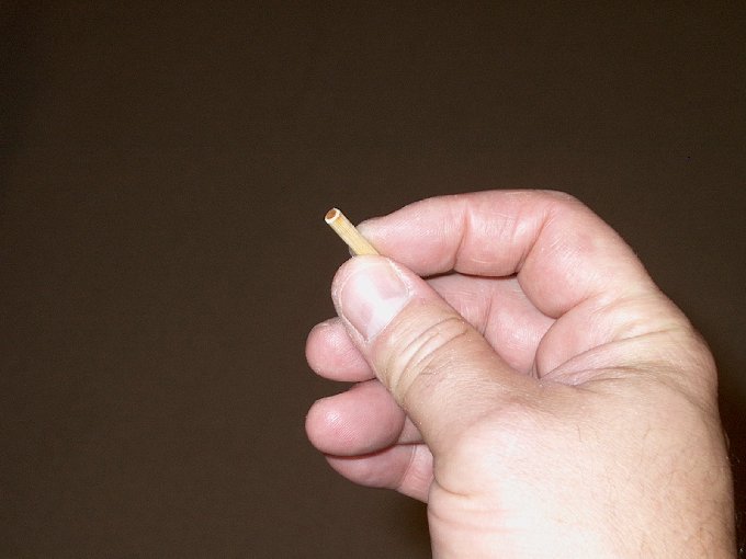
20 - Removing the wire puller thread.
| |
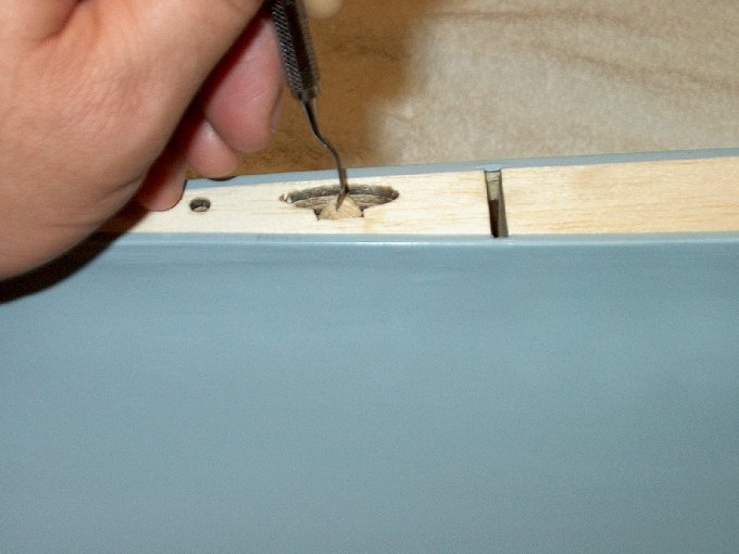
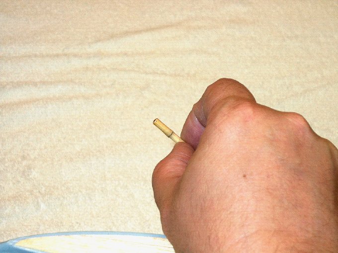
21 - A dental pick or other device was
used to break the stick loose, then used to remove it.
| |
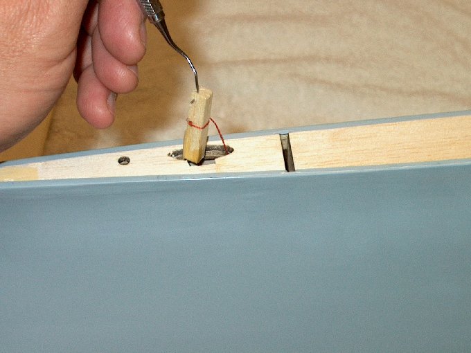
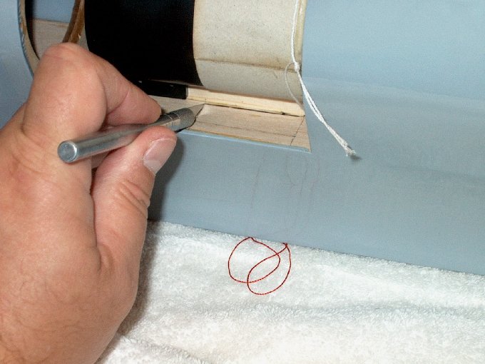
22 - Removing the puller.
| |
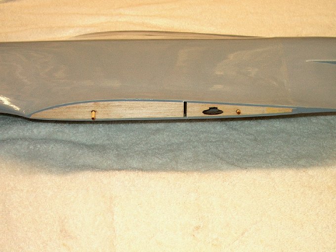
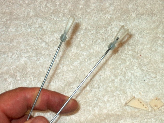
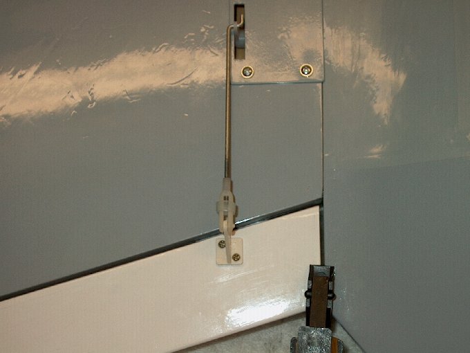
23 - The other end of these strings are
pre-threaded to the front cockpit area of the fuselage by the
factory. They are used to pull the servo extension wires from
the cockpit area through to a servo in each wing.
| |
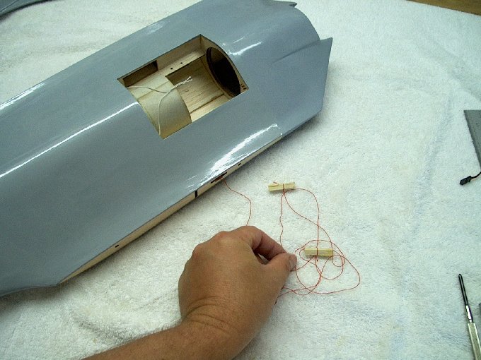
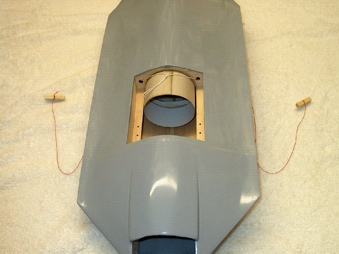
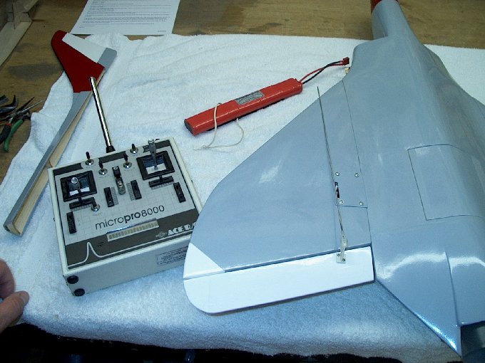
24 - I decided not to mount the receiver
in the cockpit area, so the RED pulling thread was removed.
| |
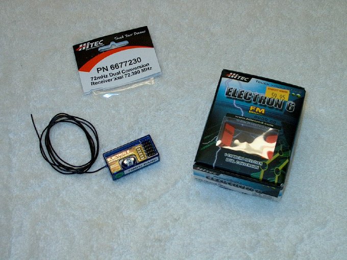
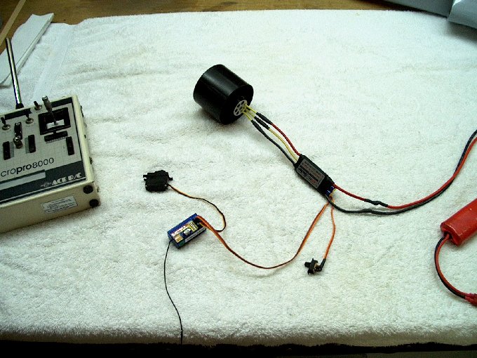
25 - A dual conversion high quality
receiver is recommended for this model.
| |
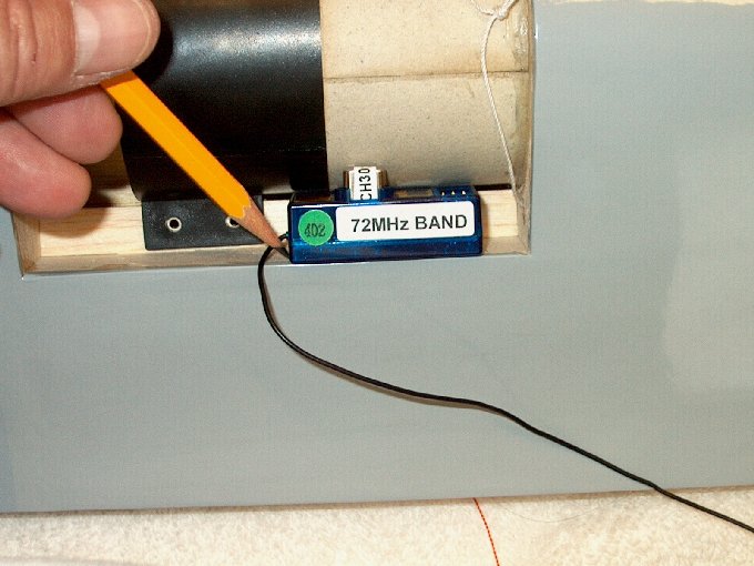
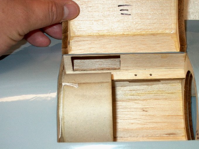
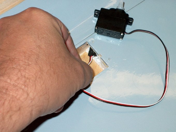
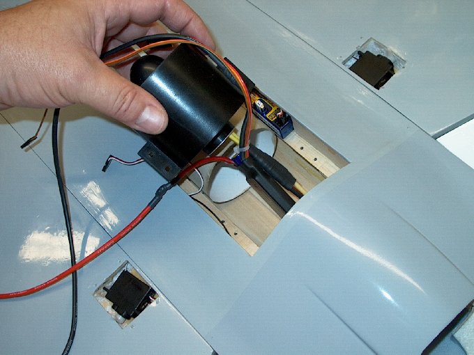
26 - The receiver will be mounted next to
the fan unit, similar to the HET-RC FA-18 Hornet. This will
eliminate the need to route three long servo extensions and
leave more room in the cockpit for batteries.
| |
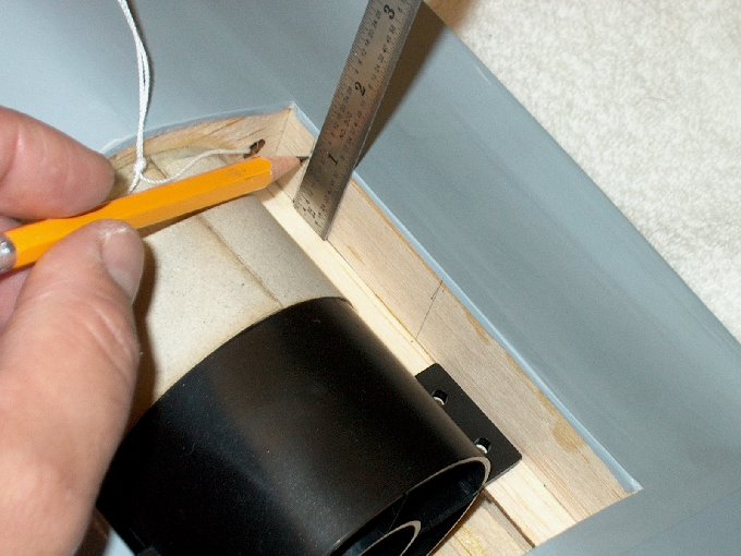
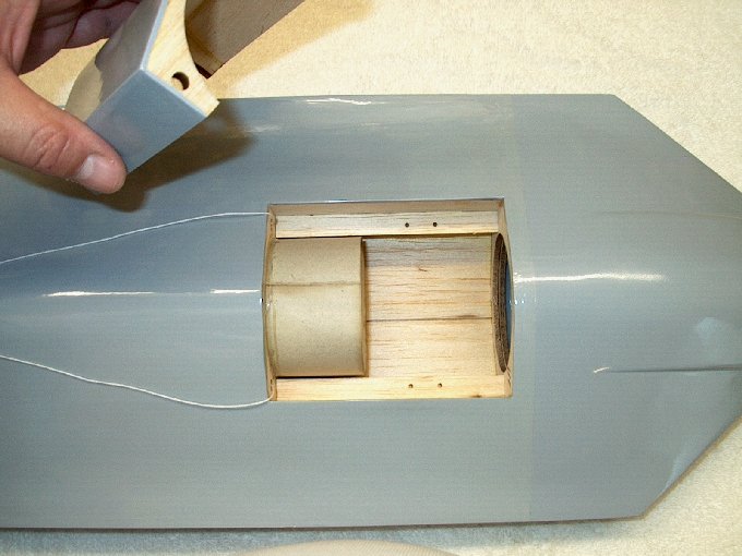
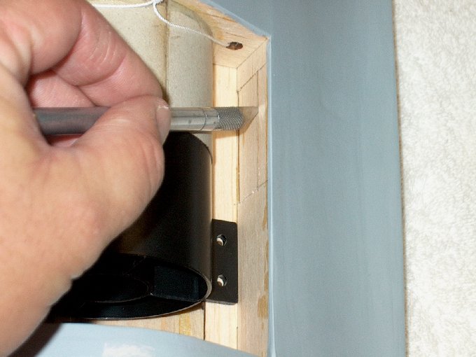
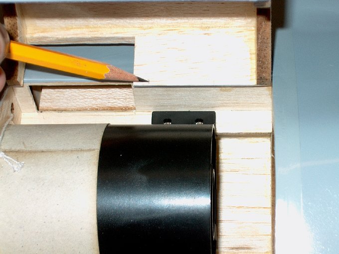
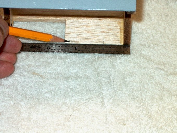
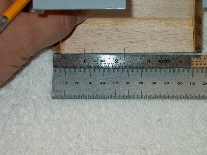
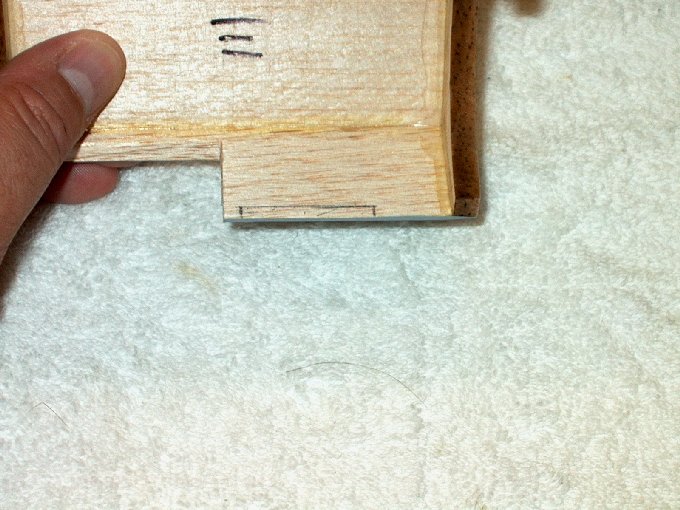
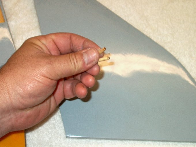
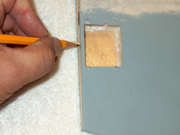
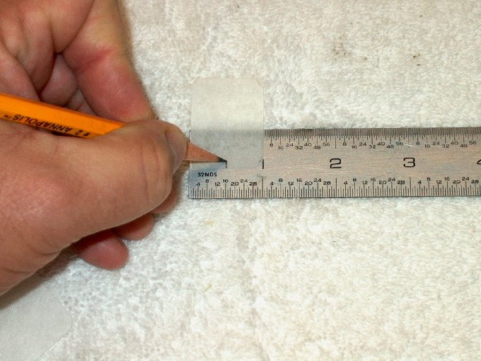
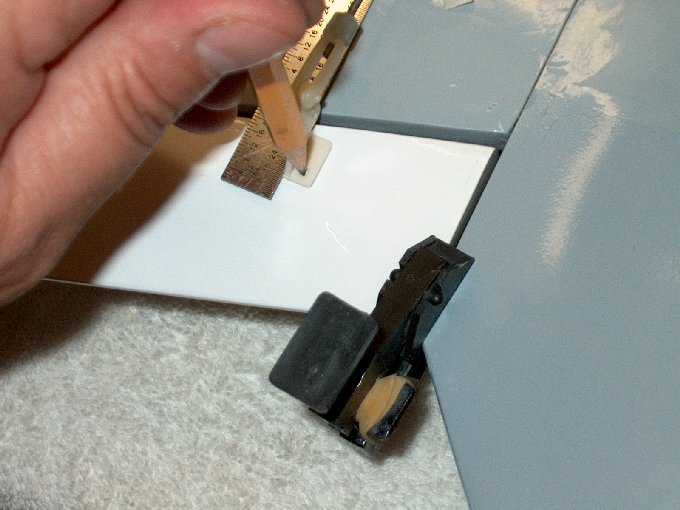
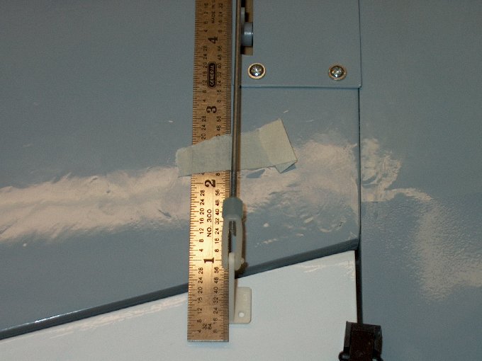
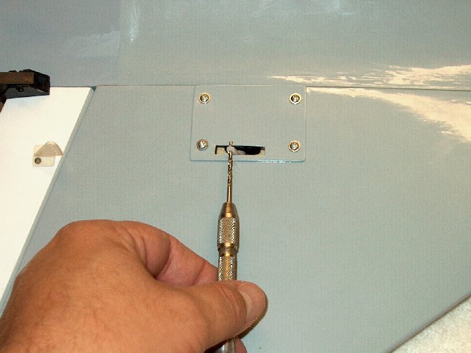
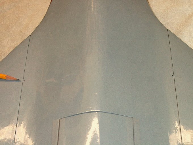
27 - Make a mark 1/4" or more from the
front wall and a second mark for the length of your receiver.
| |
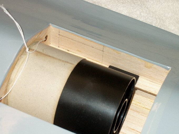
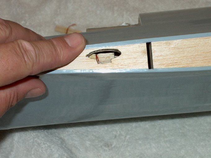
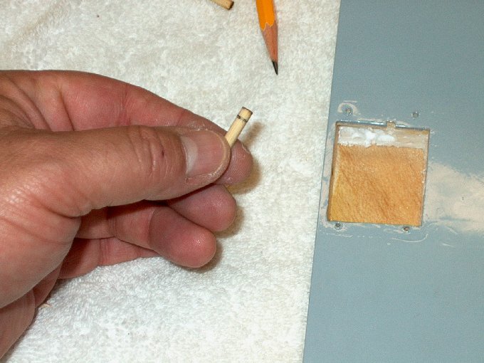
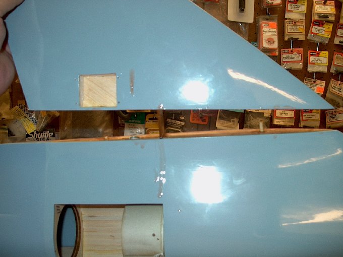
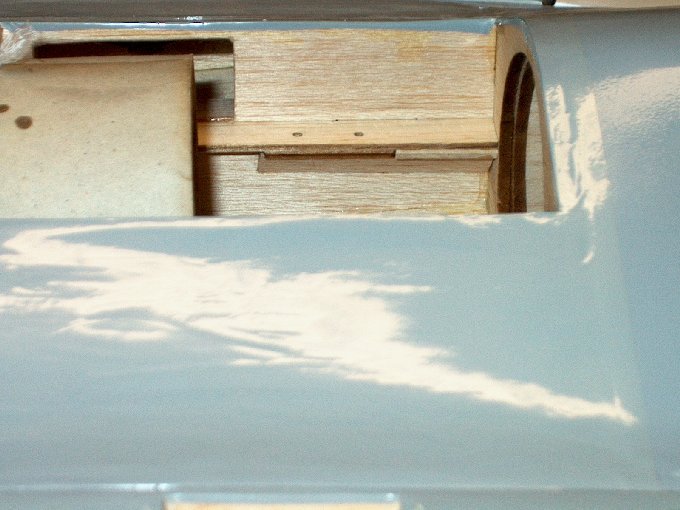
28 - Area that needs to be removed for the
reciever. | |
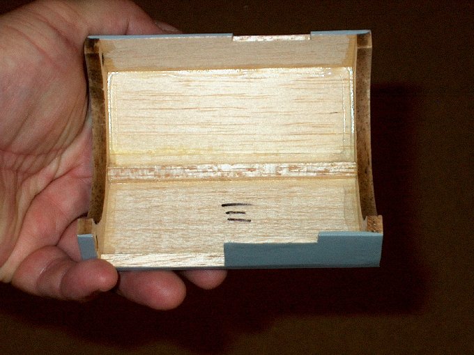
29 - The location was cut out.
| |
30 - Horizontal cut made.
| |
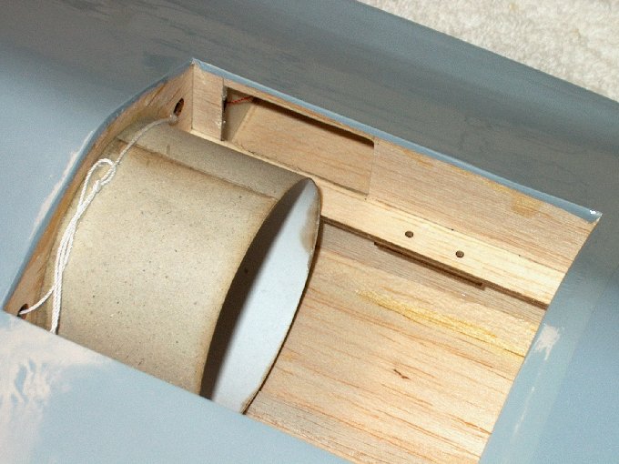
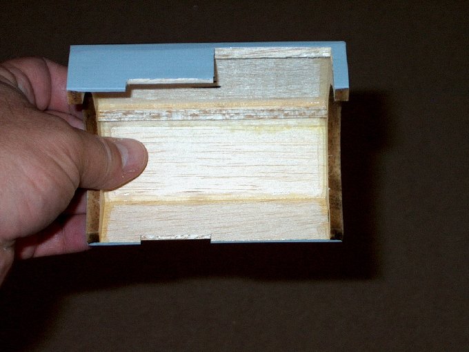
31 - Receiver area cut out.
| |
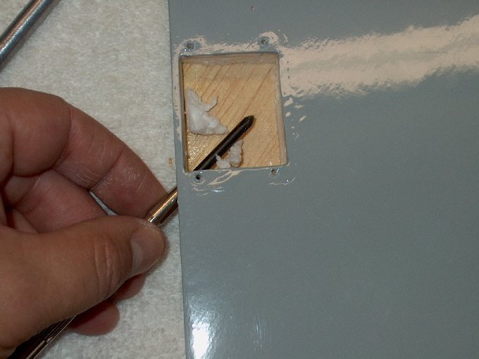
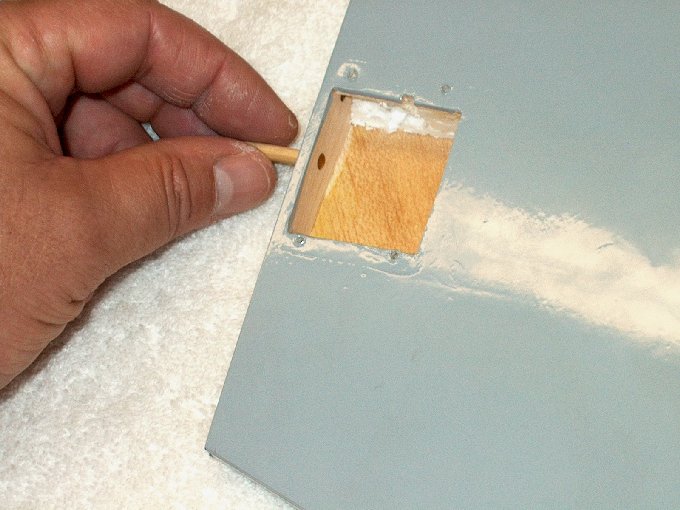
32 - Sand the area to fit your receiver.
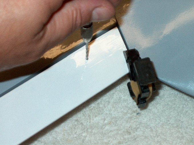
| |
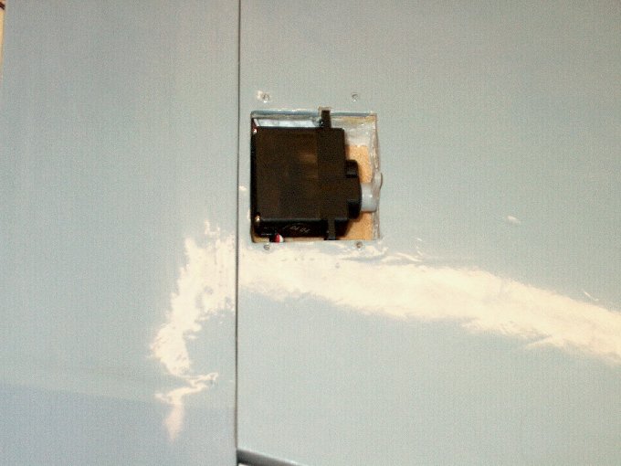
33 - The Hitec Electron 6 reciever fits
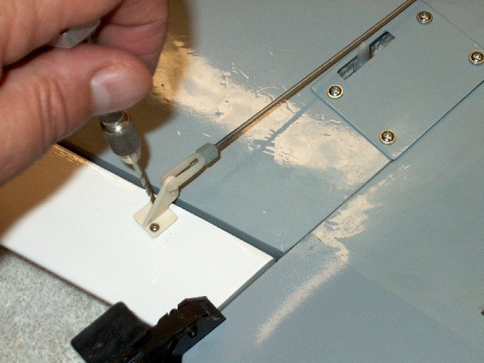
well for a 1 7/8" long hole. | |
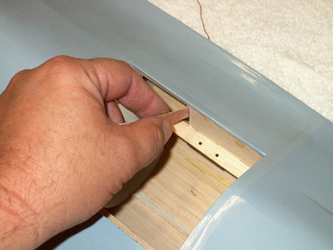
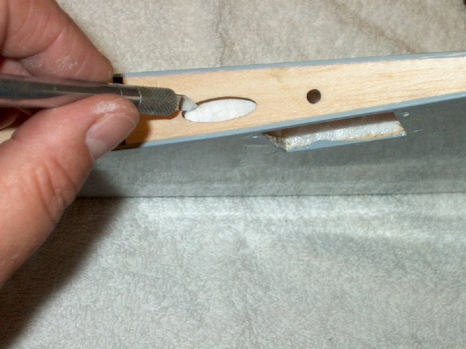
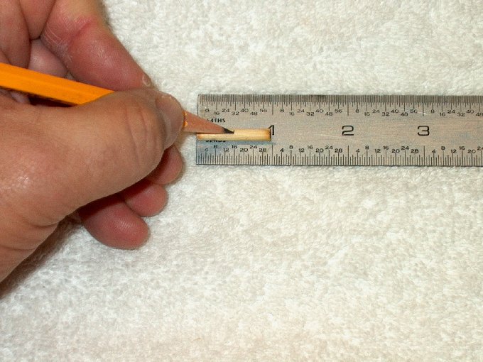
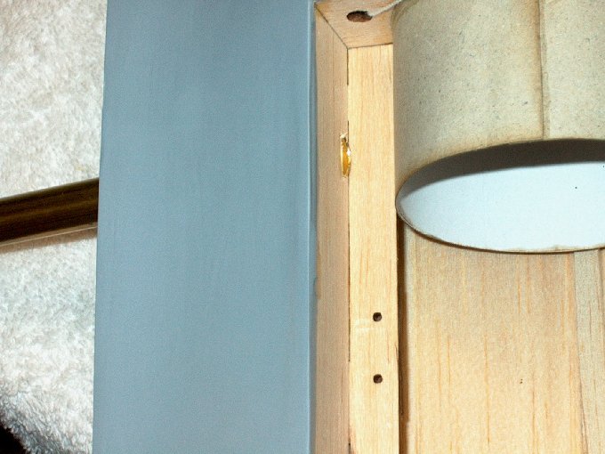
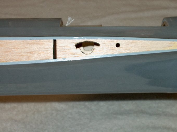
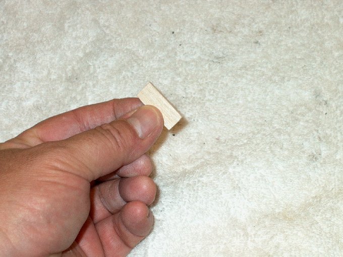
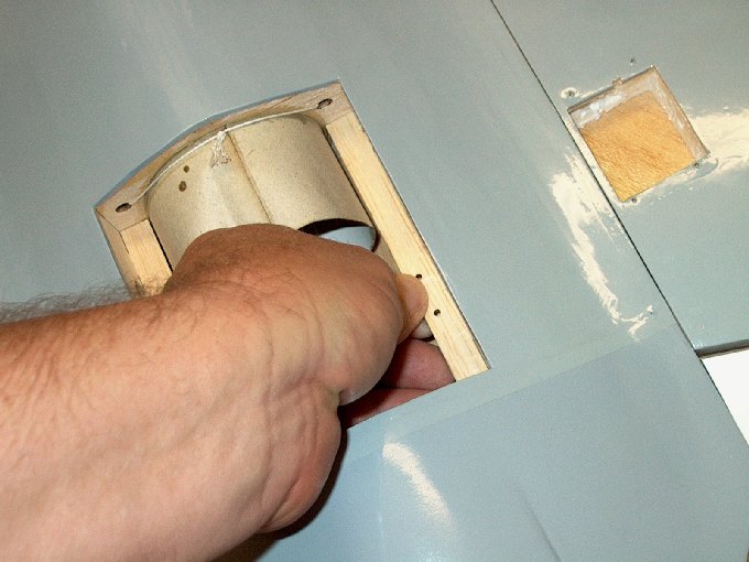
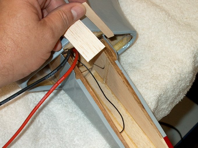
34 - A 1/2" square block was cut to extend
the platform for the receiver. | |
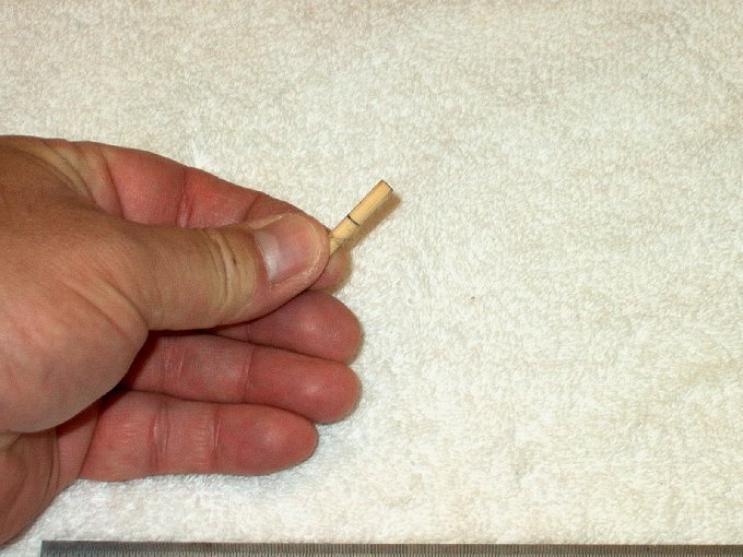
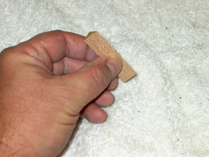
35 - A block was inserted...
| |
36 - ... and dropped into place.
| |
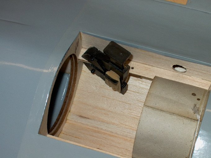
37 - An exacto knife was used to "spear"
the block and hold it in place from the wing servo hold on the
side. | |
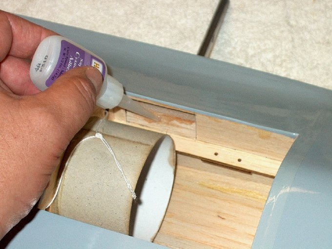
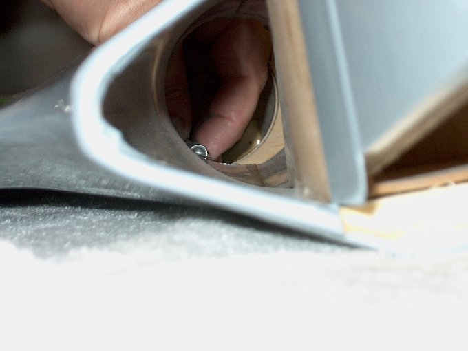
38 - Thick CA was applied to the block.
| |
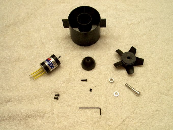
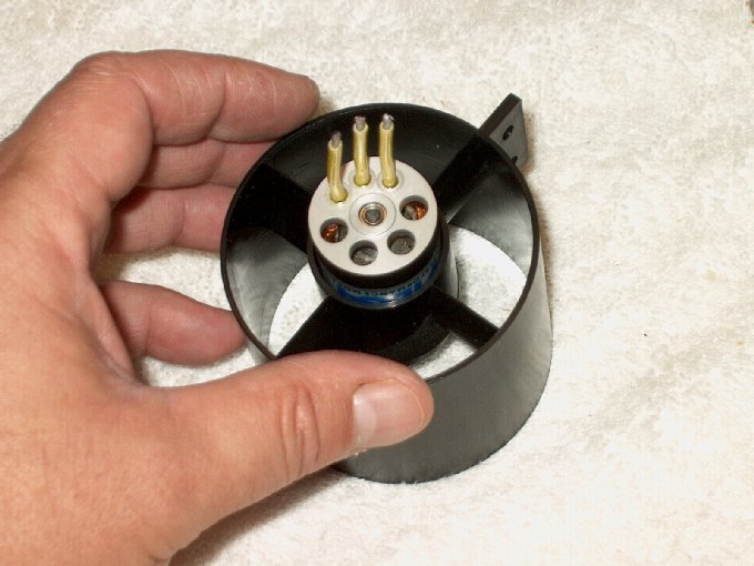
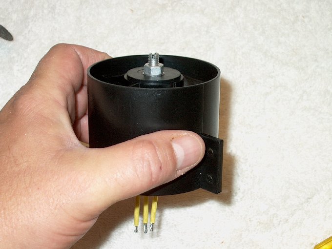
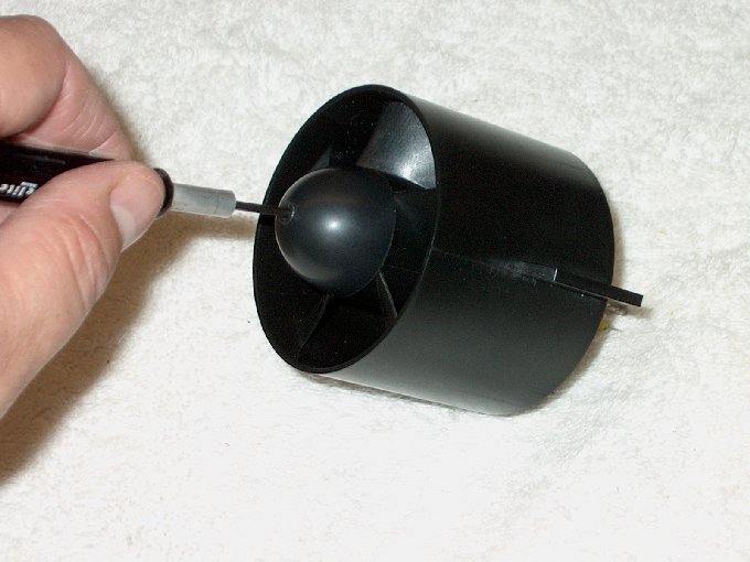
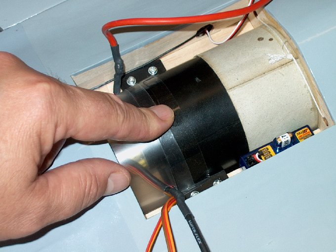
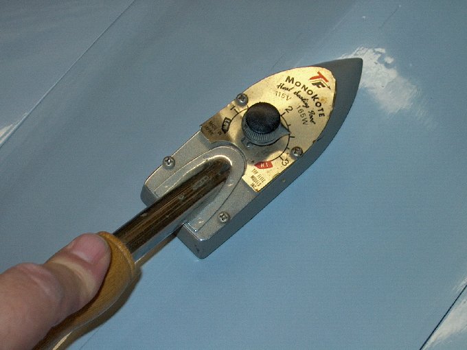
39 - the exacto knife was used to position
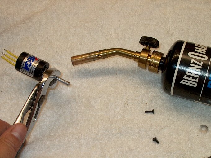
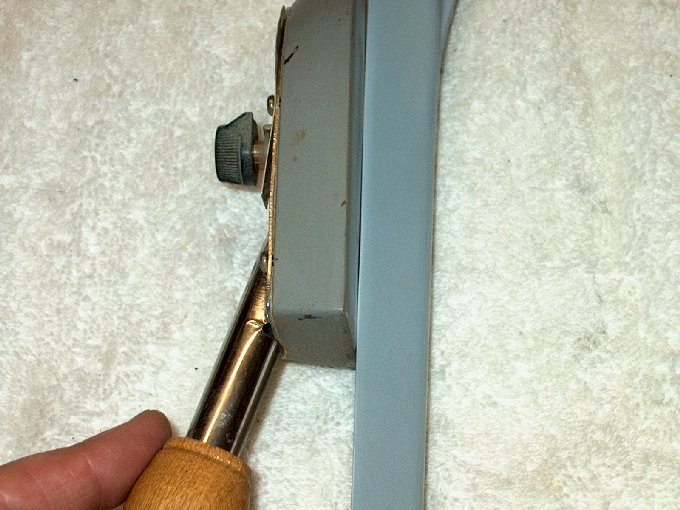
the block, making a nice and wide area now for the receiver to
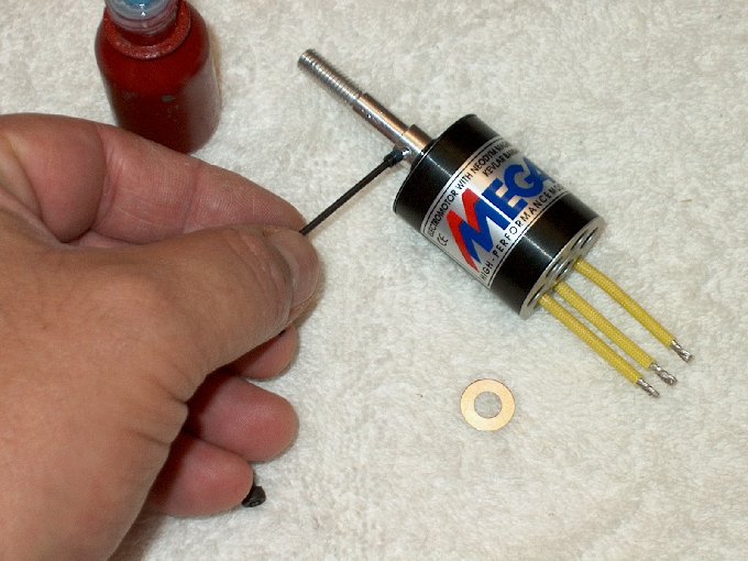
be taped. | |
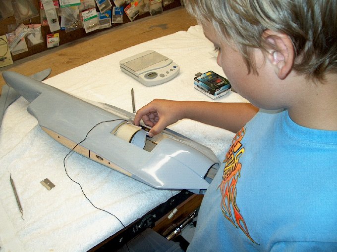
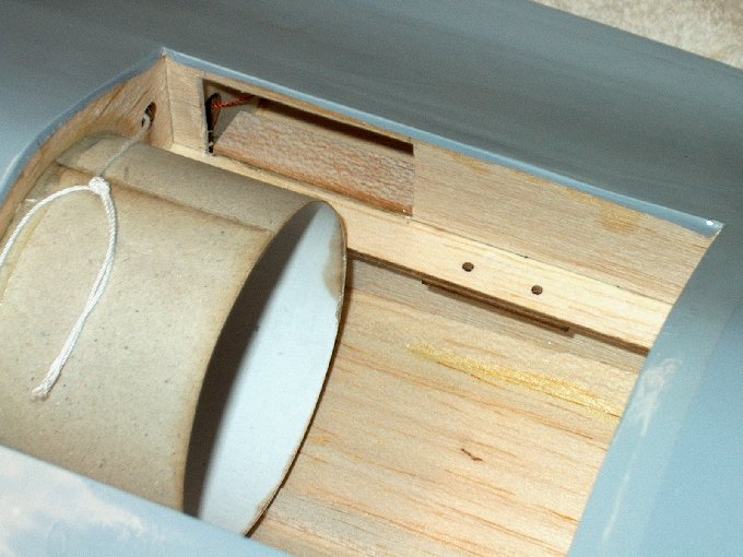
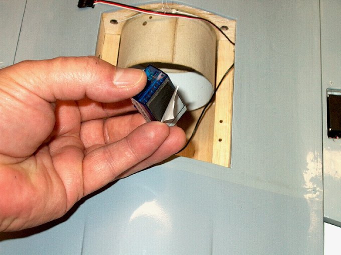
40 - The receiver fits easy enough for a
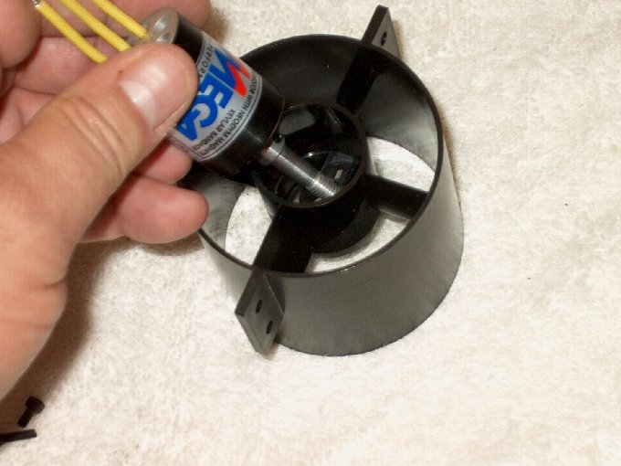
child to install. | |
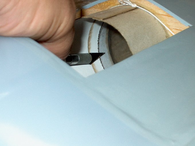
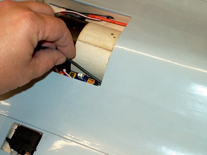
41 - The cover will need to be opened so
it fits over the receiver. | |
42 - Cover was marked, then the area was
cut. | |
43 - The fan shroud was temporarily
installed to mark mounting areas. | |
44 - Two marks were made from the rear of
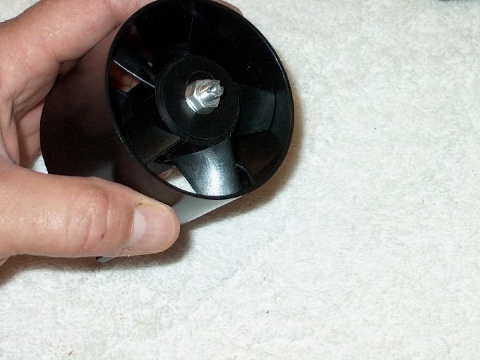
the cover... one mark at 1" and another at 2 1/4".
| |
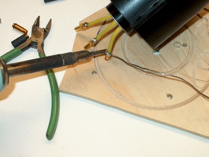
45 - For our friends overseas, this would
be 25mm and 58mm. | |
46 - The other side of the hatch was
marked. | |
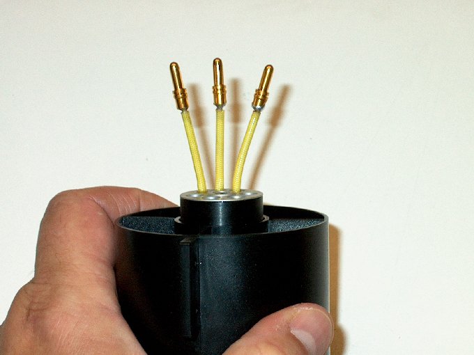
47 - A 1/8" or 3mm wide strip was measured
between the lines. | |
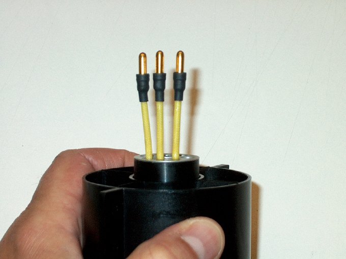
48 - ... and a line was drawn.
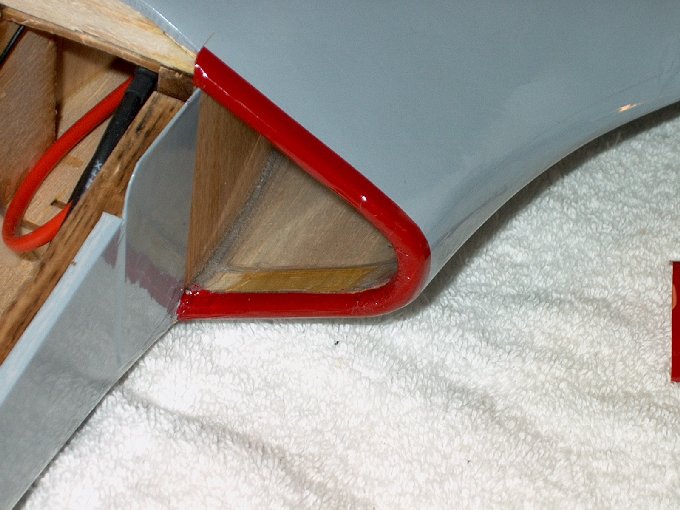
| |
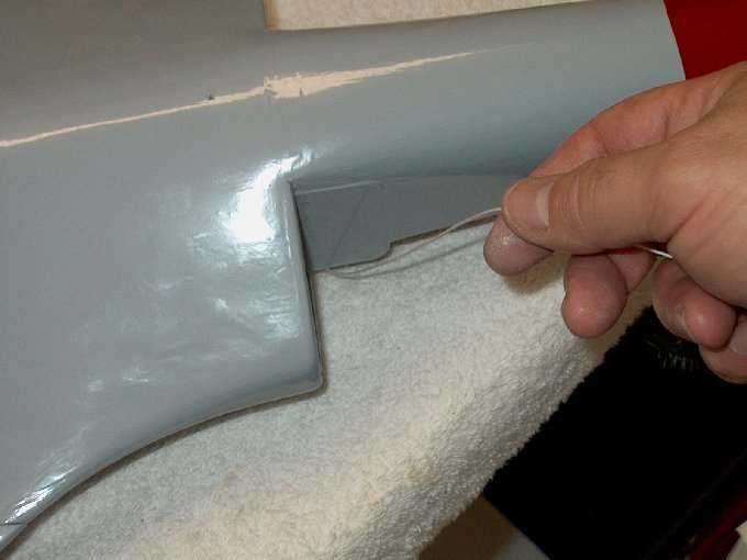
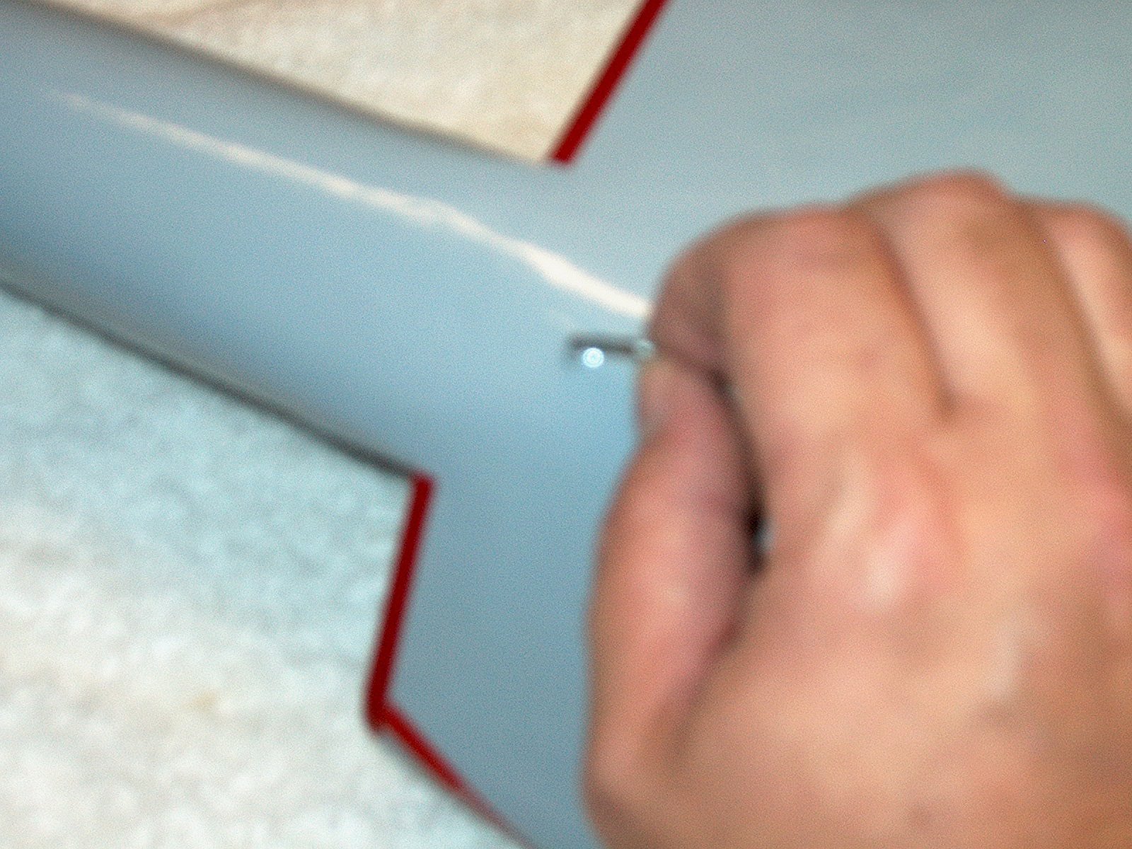
49 - This area needs to be
removed in order for the lid to clear the fan shroud mounts.
| |
50 - Balsa removed from
both sides. | |
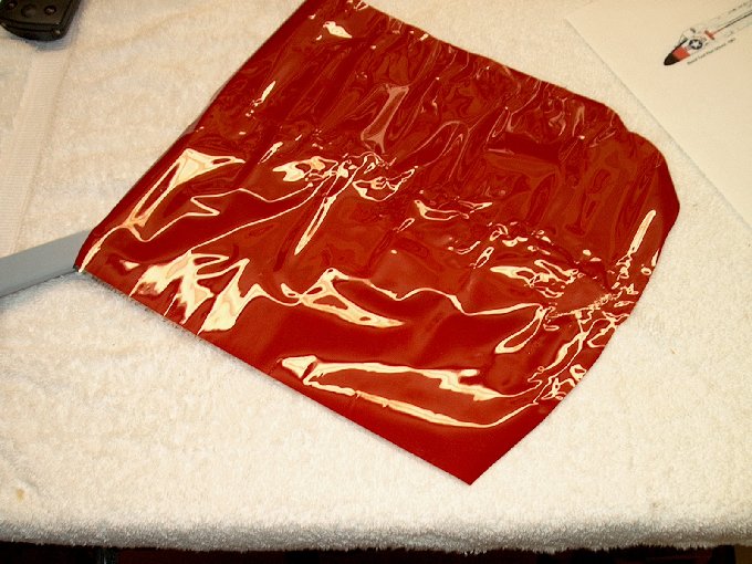
51 - Another view... hatch
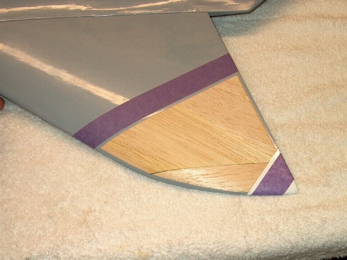
is ready to use. | |
52 - Beginning the
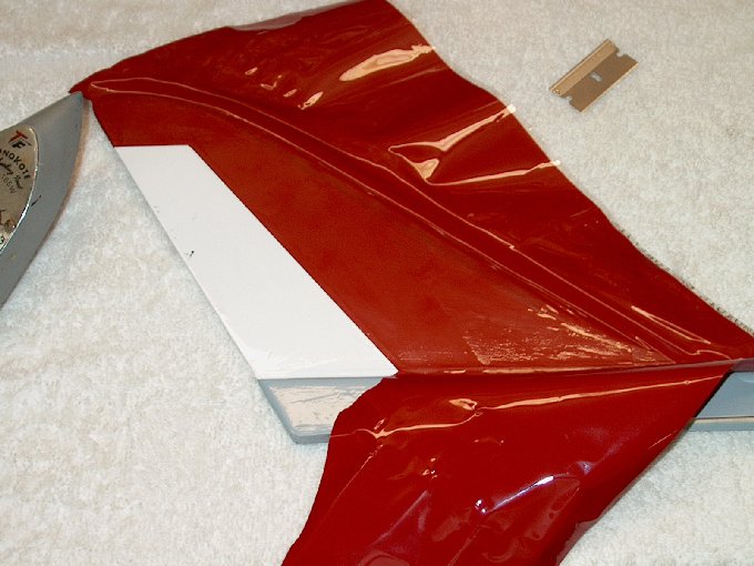
build... foam is removed from the wing for servo wires.
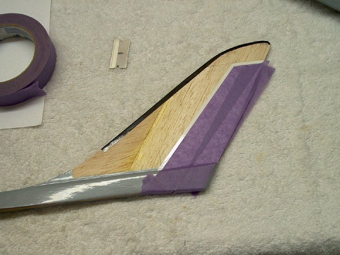
| |
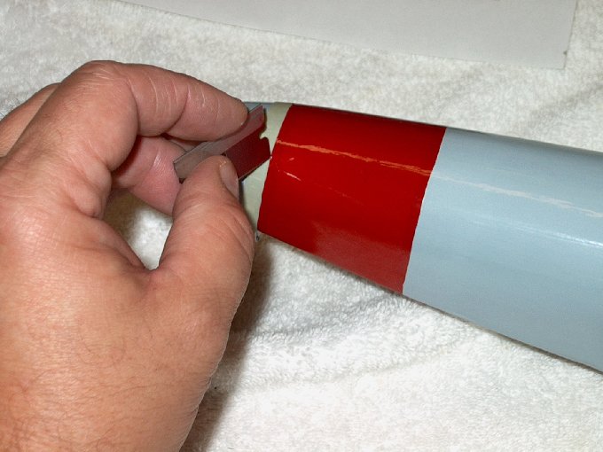
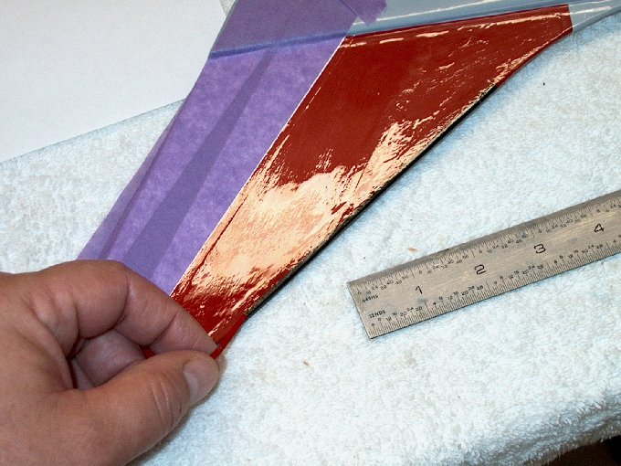
53 - The foam was pushed
out. | |
54 - Then the area filed.
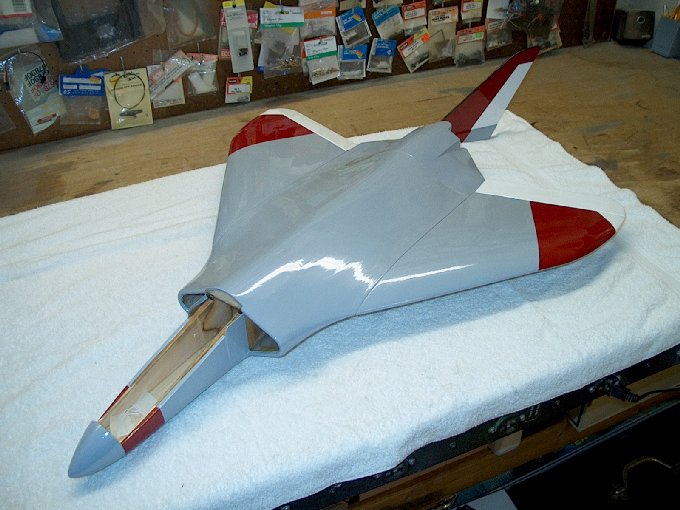
| |
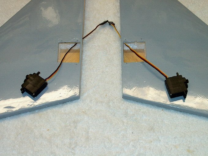
55 - Picture showing wires
routed through the wing. | |
56 - Close-up showing wire
routed through foam wing. | |
57 - Beveling the edges of
the dowels for easy insertion. | |
58 - End beveled.
| |
59 - both dowels
ready | |
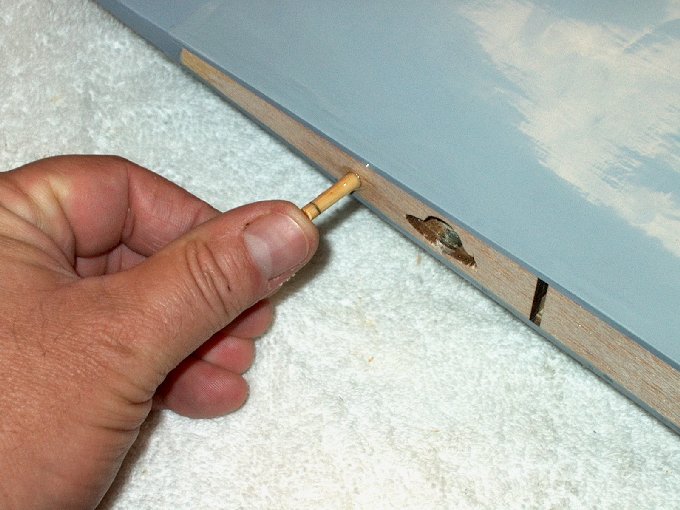
60 - Dowel is inserted so
it is flush with the inside of the wing .
| |
61 - The outside of the
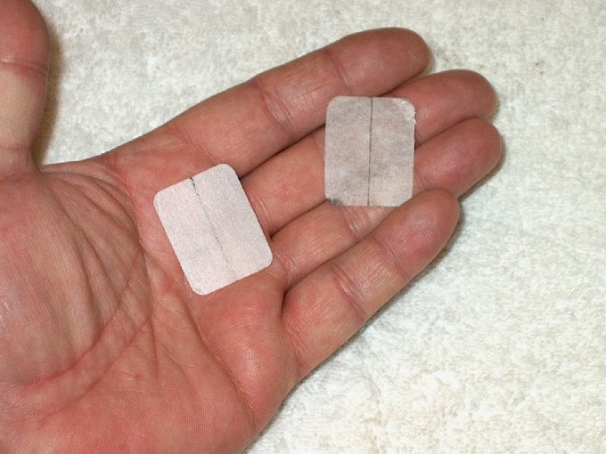
dowel is marked for position. | |
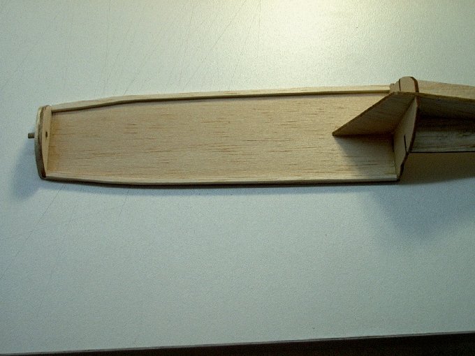
62 - Marked dowel ready to
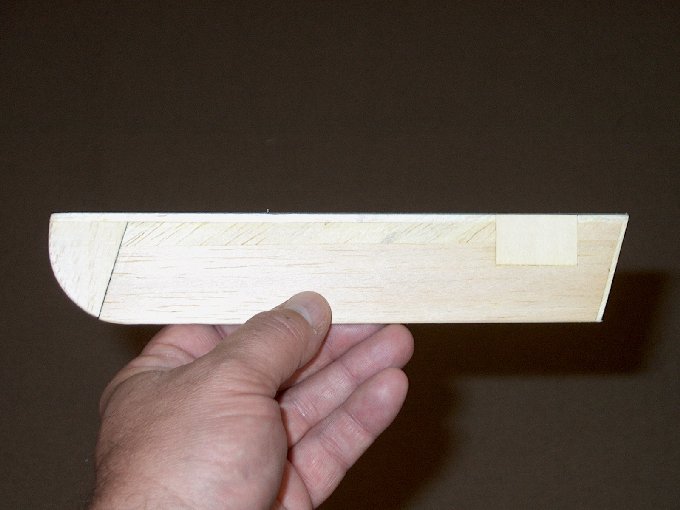
install. | |
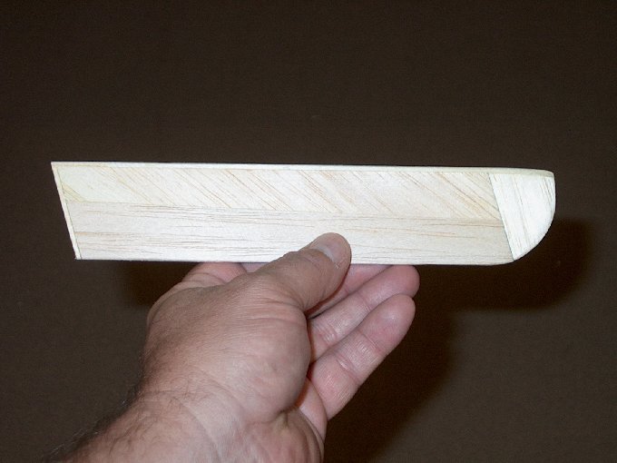
63 - Forward dowel, marked
at 1/2" dead center. | |
64 - Forward dowel
marked. | |
65 - 5 minute epoxy
applied to forward dowel. | |
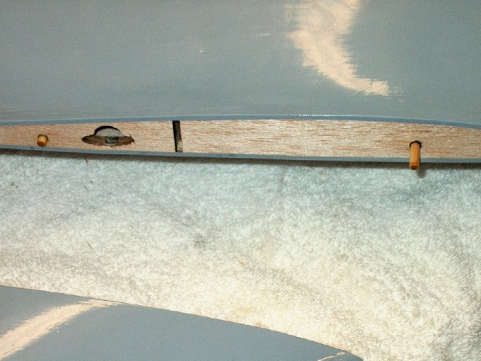
66 - Forward dowel
inserted in fuselage up to the line that was drawn.
| |
67 - Rear dowel with 5
minute epoxy inserted in fuselage up to the short line.
| |
68 - Excess epoxy was
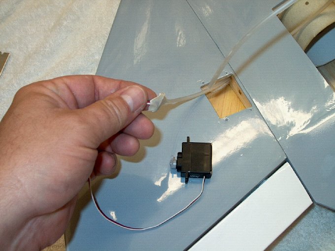
cleaned up with a paper towel and some denatured alcohol, then
left to set. | |
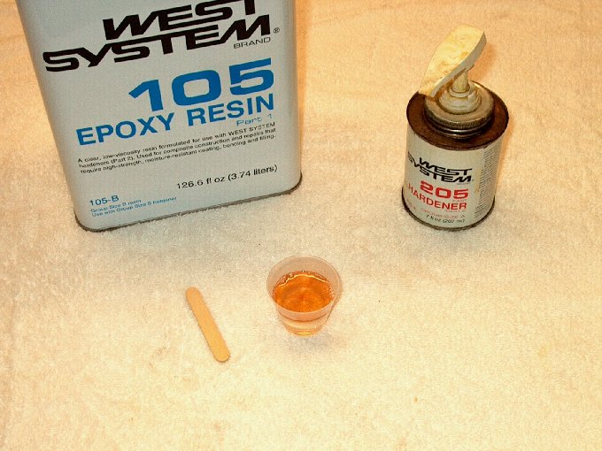
69 - Mixing up the good
stuff for wing mounting. | |
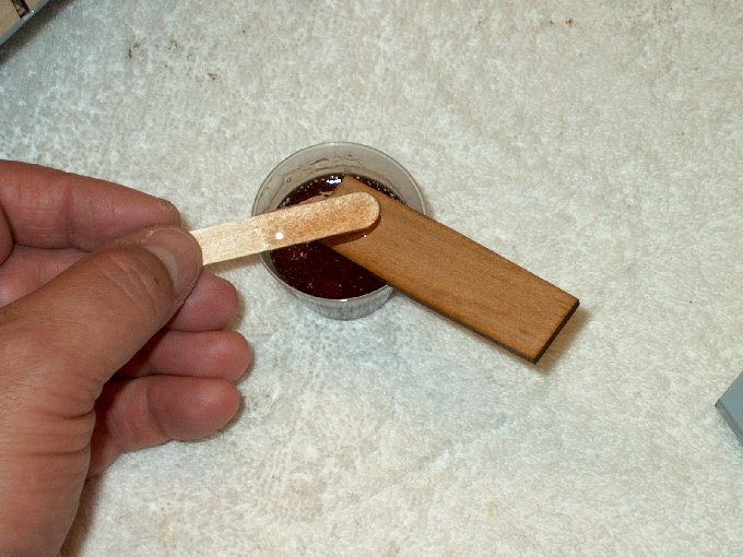
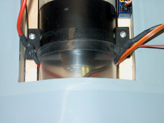
70 - Epoxy applied to wing
spar. | |
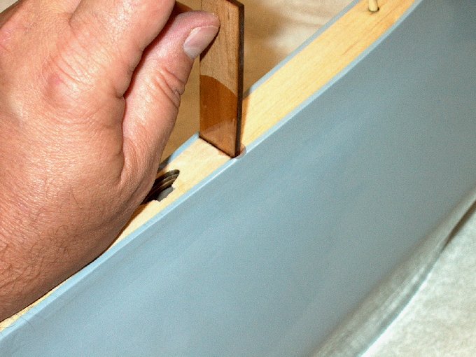
71 - Epoxy applied inside
slot, then spar inserted. The spar can go in either way,
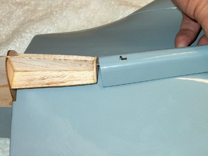
making installation easier. | |
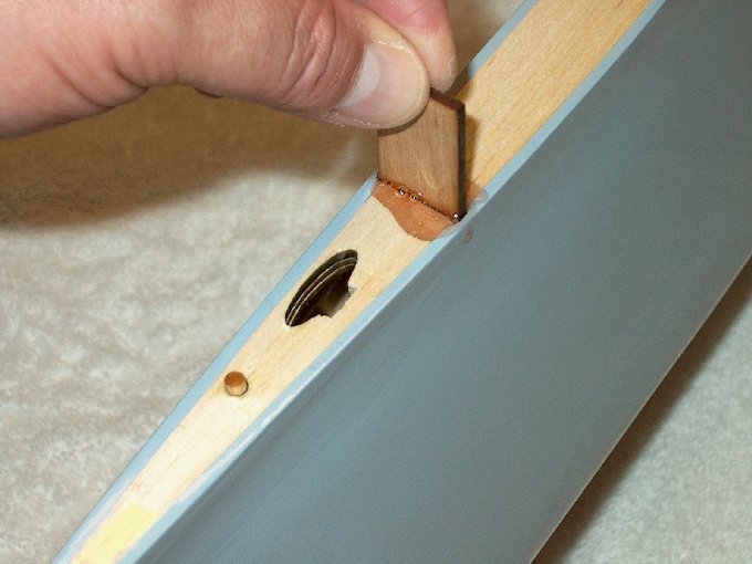
72 - Spar will bottom out
inside the fuselage. | |
73 - Applying epoxy to the
fuselage root. | |
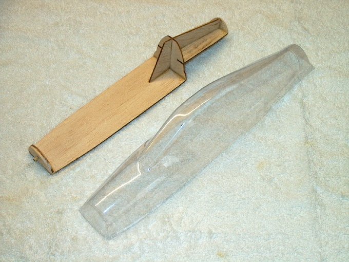
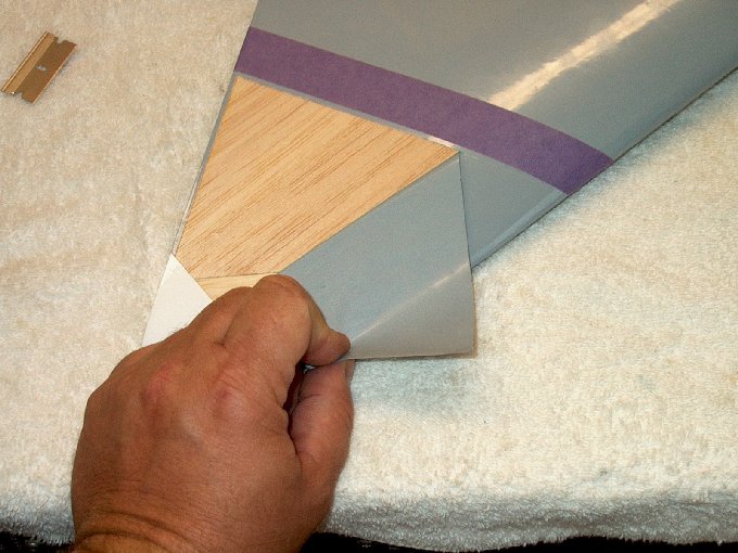
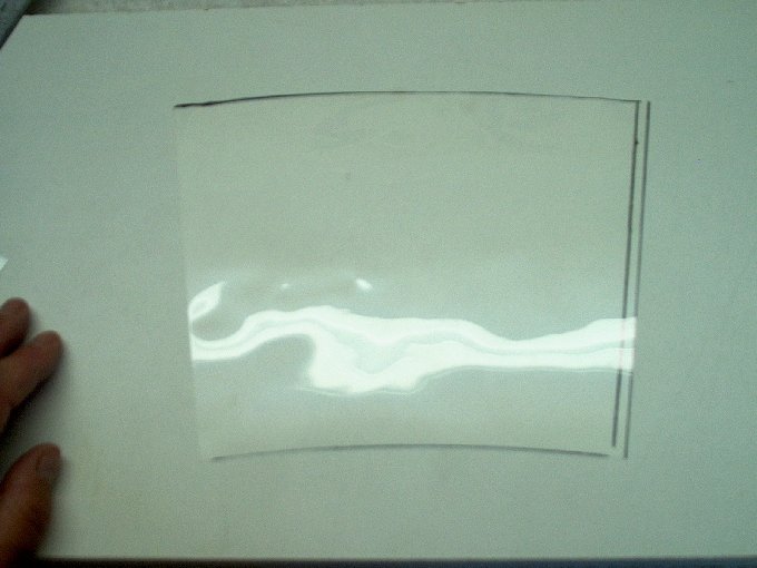
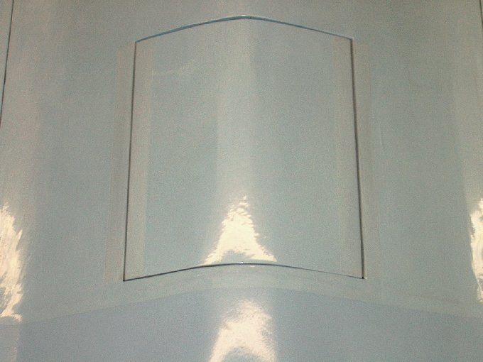
74 - Fuselage with epoxy
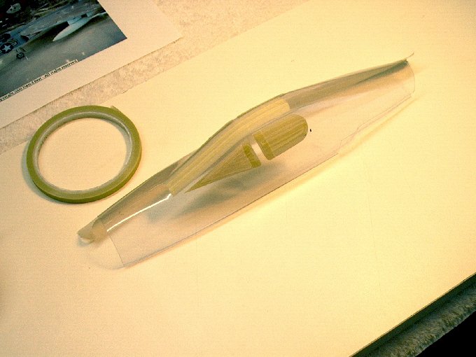
applied. | |
75 - Epoxy next applied to
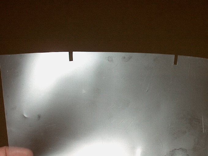
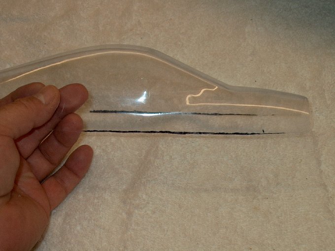
wing spar slot. | |
76 - Epoxy applied to entire wing root and
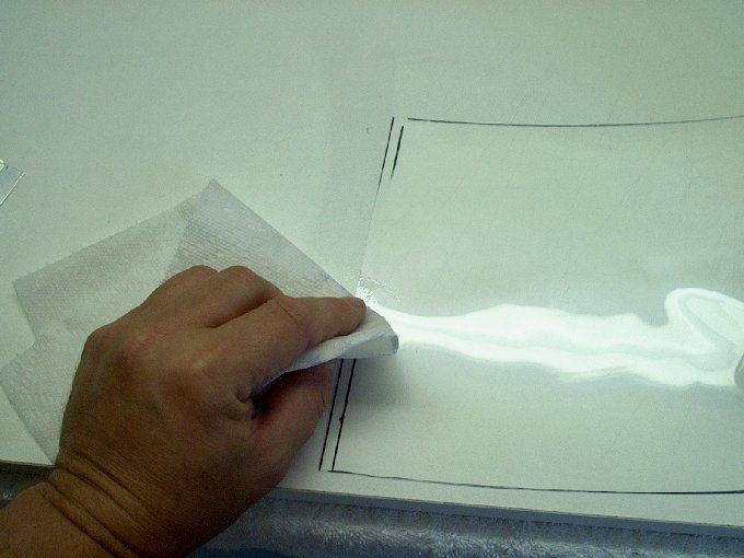
dowel holes. | |
77 - Wing with epoxy ready to install.
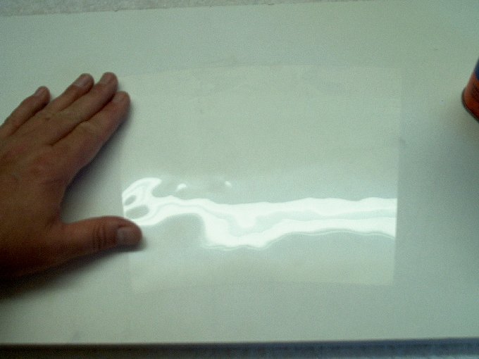
| |
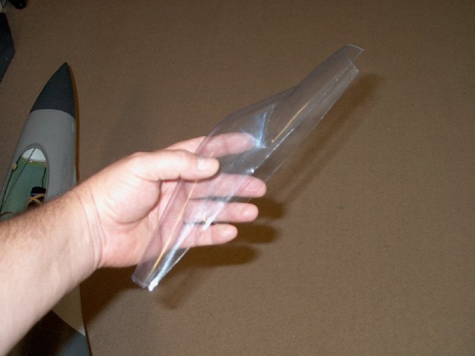
78 - Installing the wing
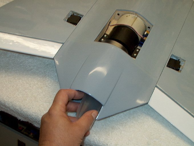
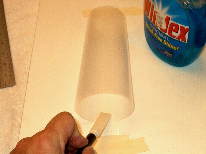
| |
79 - Wing pressed down until flush.
| |
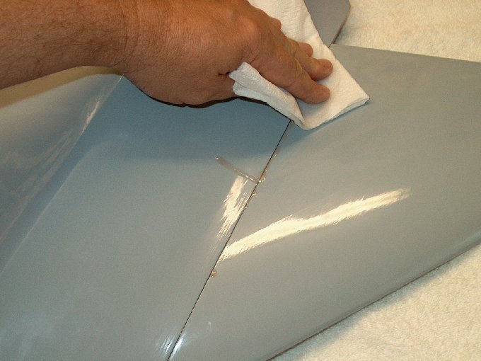
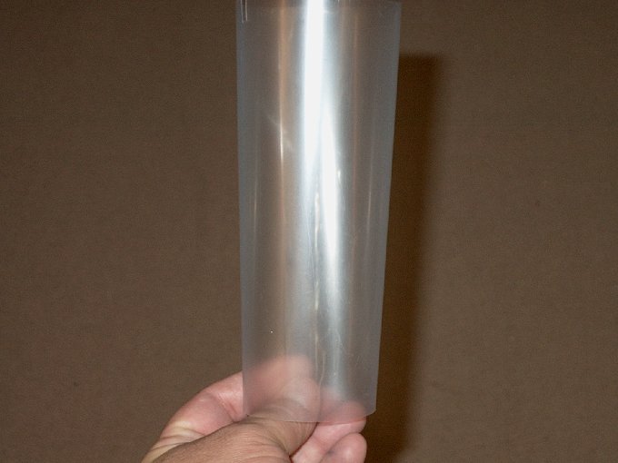
80 - Excess epoxy was removed with paper
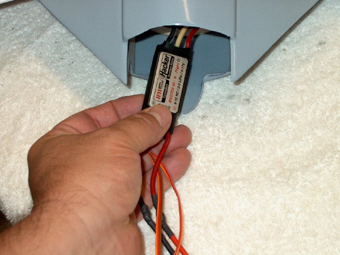
towel soaked in denatured alcohol. | |
81 - Joint cleaned and T-pins used to hold
wing in place. | |
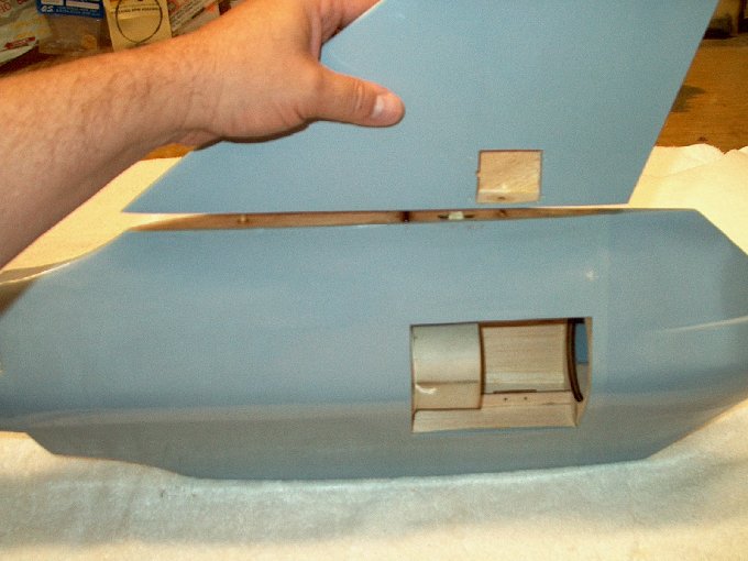
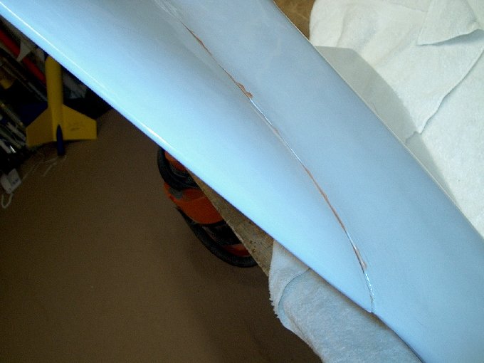
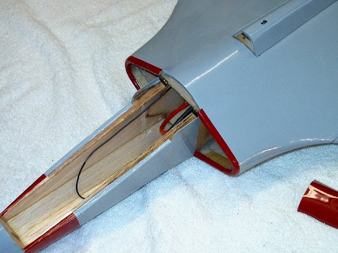
82 - Wing was mounted flush to the top of
the fuselage and a small ridge was evident at the bottom, but
will be fine. | |
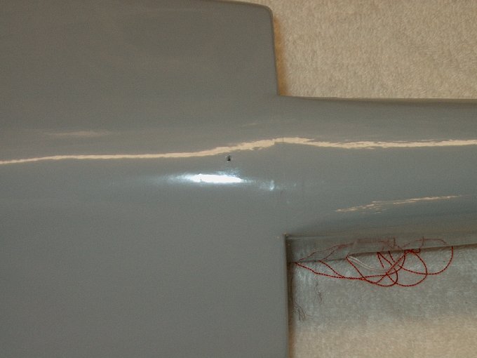
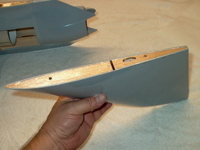
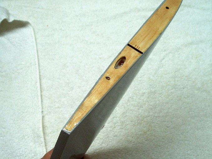
83 - Edge view of
installed and pinned wing. | |
84 - Clean up the excess
epoxy from the servo well. | |
85 - Wing pinned and epoxy
left to set. | |
86 - Wing
installed. | |
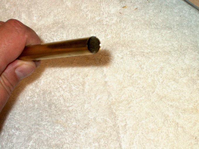
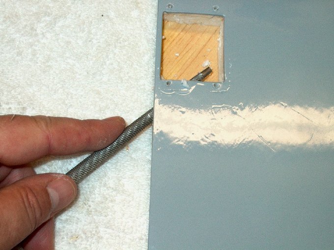
87 - A piece of 1/2" brass
tube is sharpened by shaving the inside with an exacto knife.
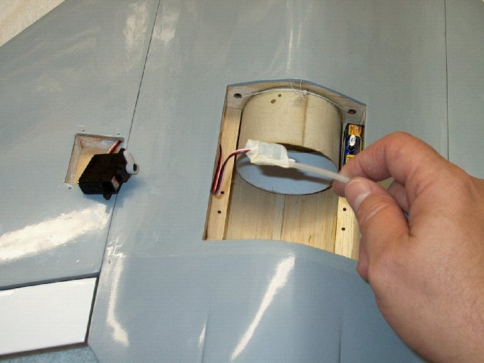
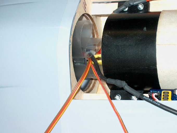
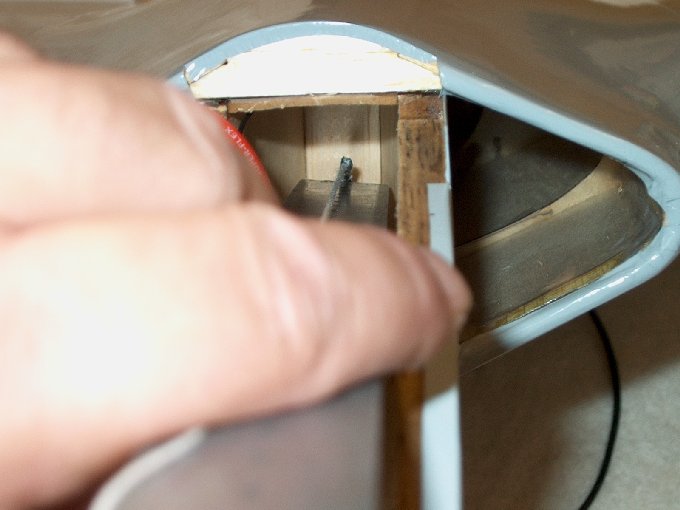
| |
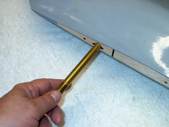
88 - Brass tube inserted
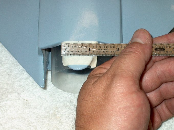
through servo access holes. | |
89 - Brass tube is used as
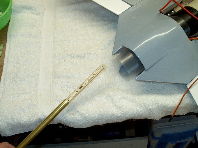
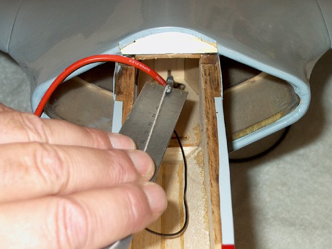
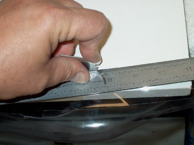
a drill to make a hole for the servo wires.
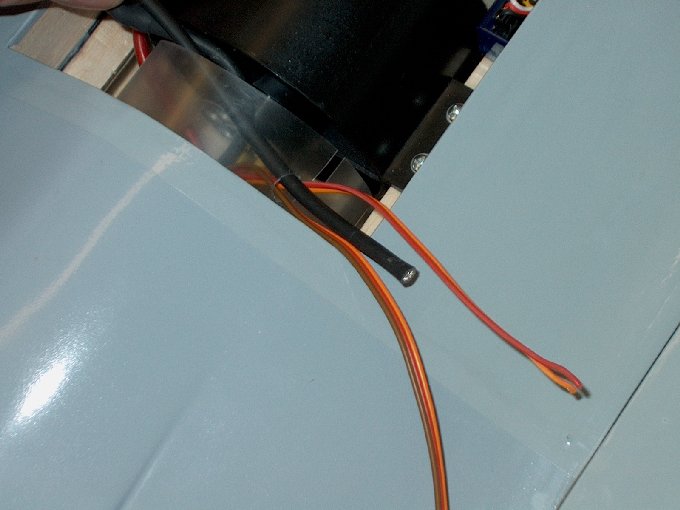
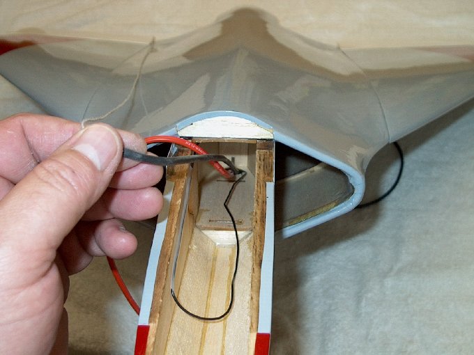
| |
90 - Tube was angled
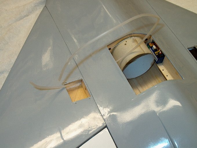
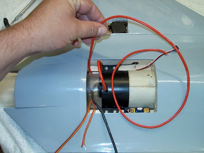
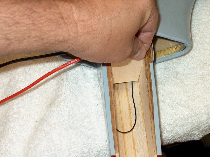
upward so it would come out inside just above the horizontal
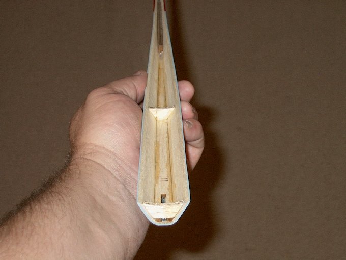
runner. | |
91 - Tube came out just
above the runner. | |
92 - Hole drilled for
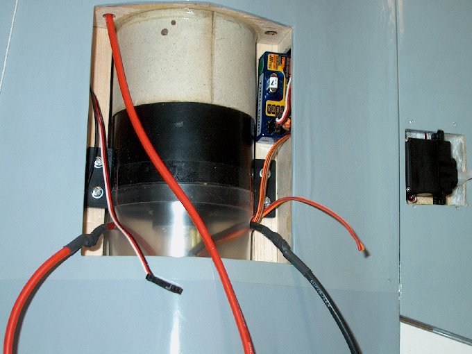
servo wires. | |
93 - Another view... you
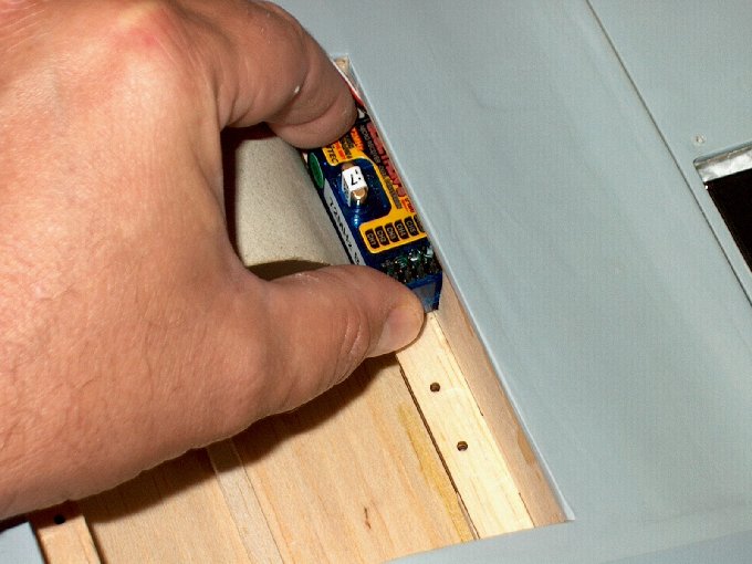
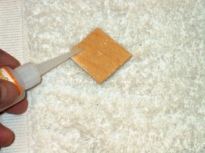
can see the fan tube through the holes.
| |
94 - Rear guide dowel
installed in other fuselage root with 5 minute epoxy.
| |
95 - Guide pins installed
and glue is set. | |
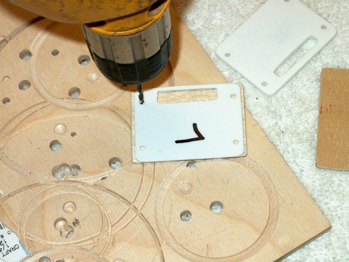
96 - Slow cure epoxy
applied to wing root. | |
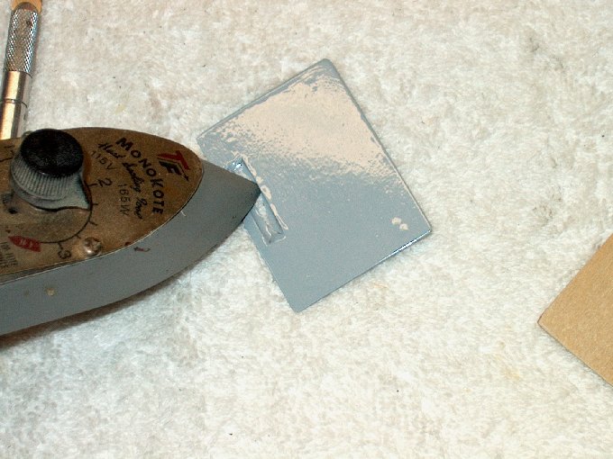
97 - Second wing installed
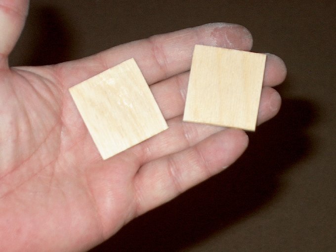
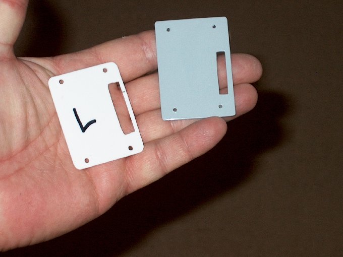
just like the first. | |
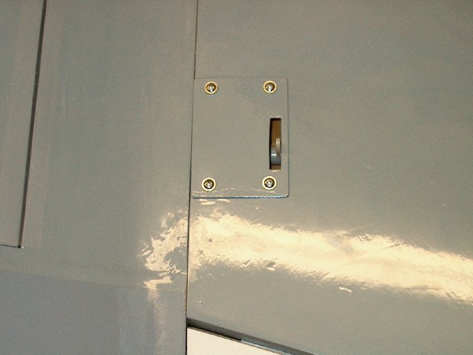
first. 98 - Epoxy was
cleaned up. | |
99 - Excess epoxy squeezed
out of the top. | |
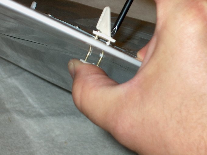
100 - Wing cleaned up and
pinned just like the first. Then placed aside so epoxy can
set. | |
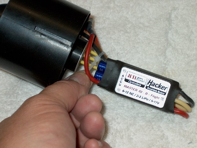
101 - The power plant... a
Wemotec MiniFan 480 and Mega AC 16-15-2.
| |
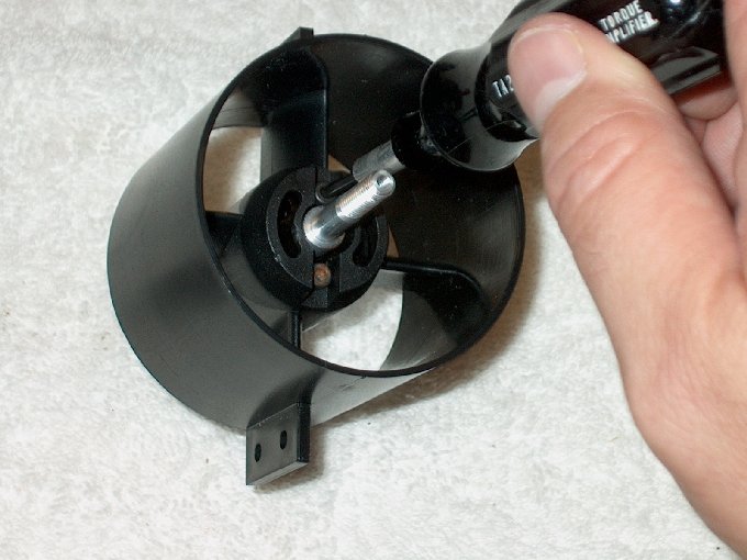
102 - Torch used to heat
up the adapter so it would slide over the motor shaft. DO NOT
push this adapter all the way on or the back of the fan will
bind against the shroud when installed.
|
|
103 - Set screws installed
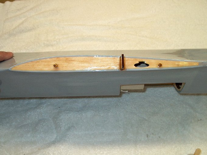
with some Loktite. | |

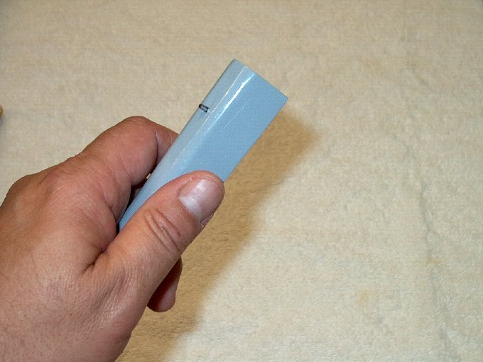
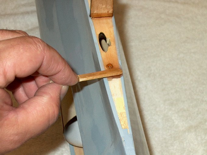
104 - Other set screw
installed... note the shaft base is not against the motor. It
had to be pulled away about 3/16" for fan clearance.
| |
105 - Installing the motor
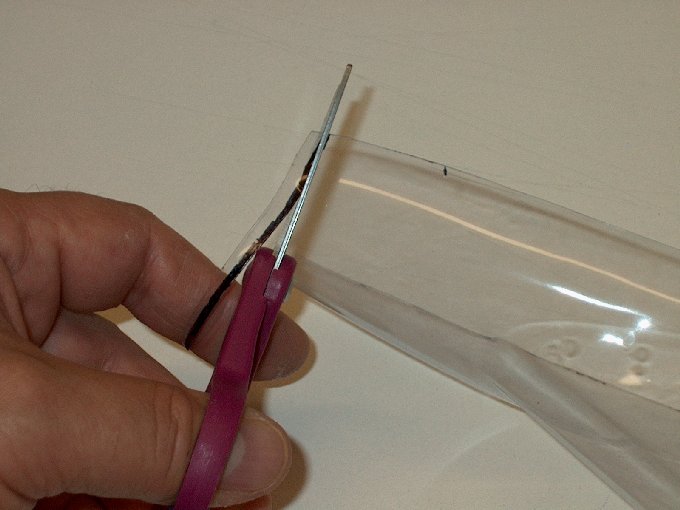
in the shroud. | |
106 - Motor intalled.
| |
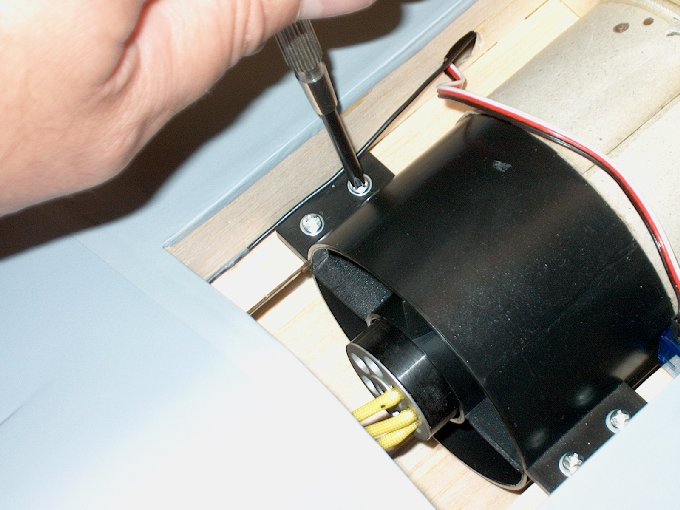
107 - 3mm screws are used
to retain the motor. The fan unit comes with 2.5mm screws, so
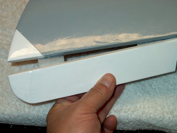
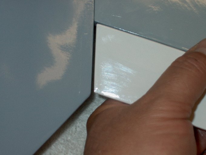
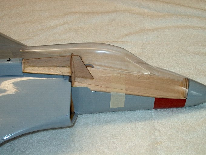
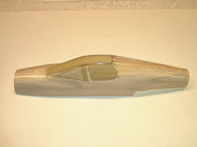
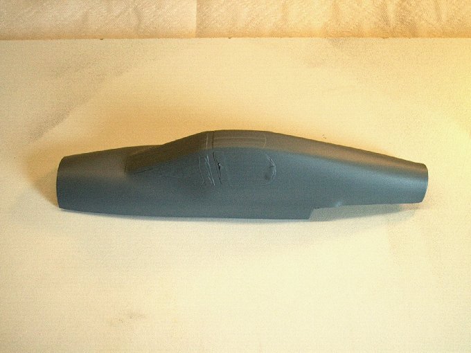
you will have to buy 3mm screws if needed.
| |
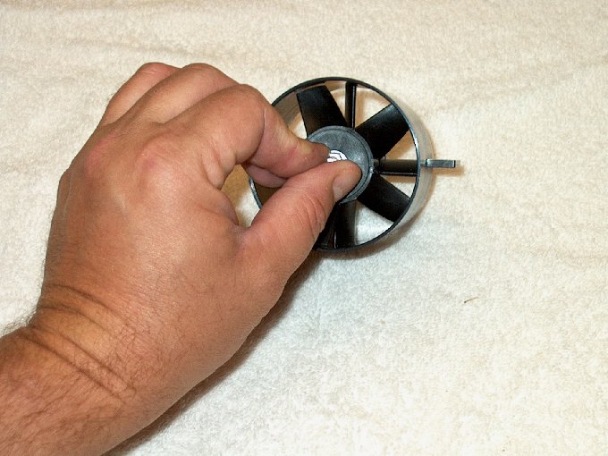
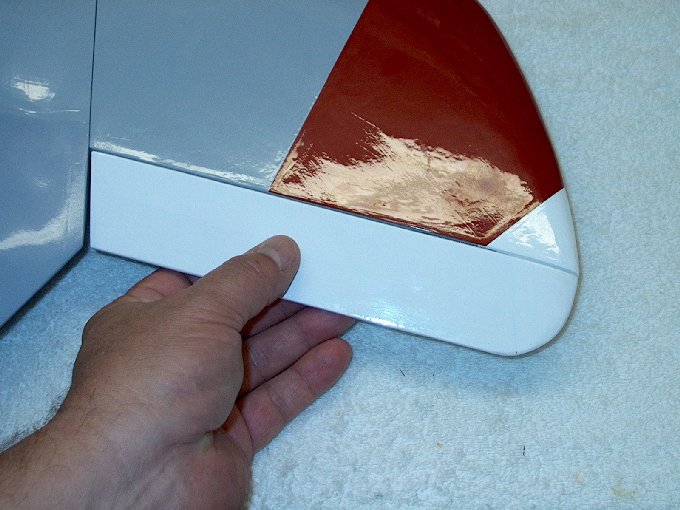
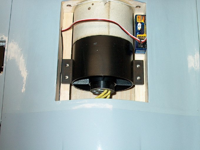
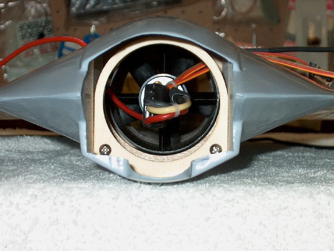
108 - Fan installed,
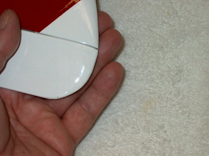
followed by washer and nut. | |
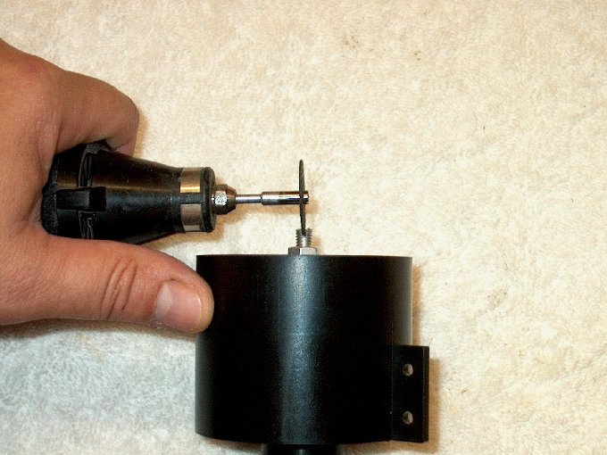
109 - Shaft adapter
slotted for screwdriver. | |
110 - Bolt slotted.
| |
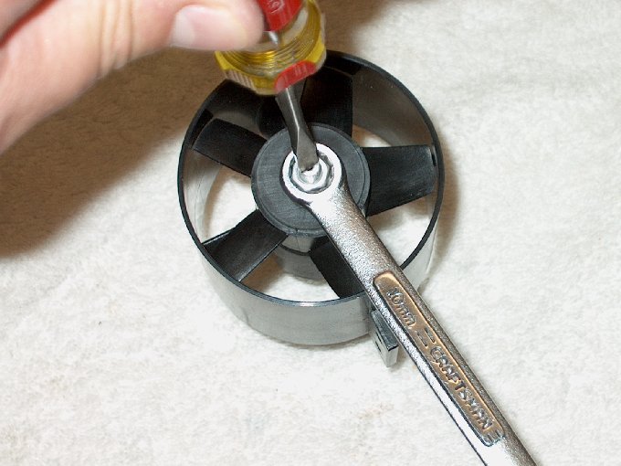
111 - With shaft slotted,
a screwdriver can hold the shaft still while the nut is
tightened. | |
112 - Nut
installed. | |
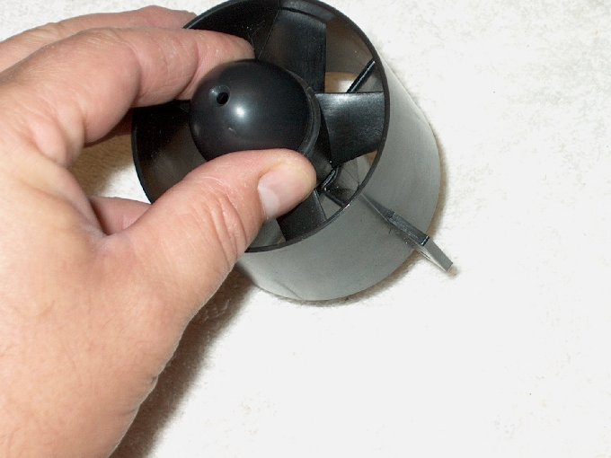
113 - Fan hub installed...
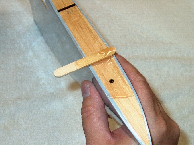
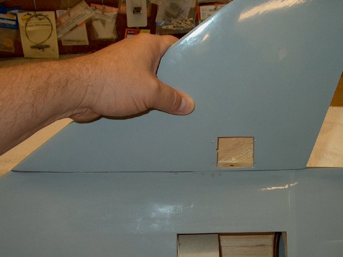
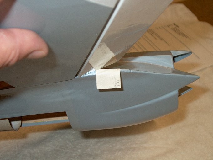
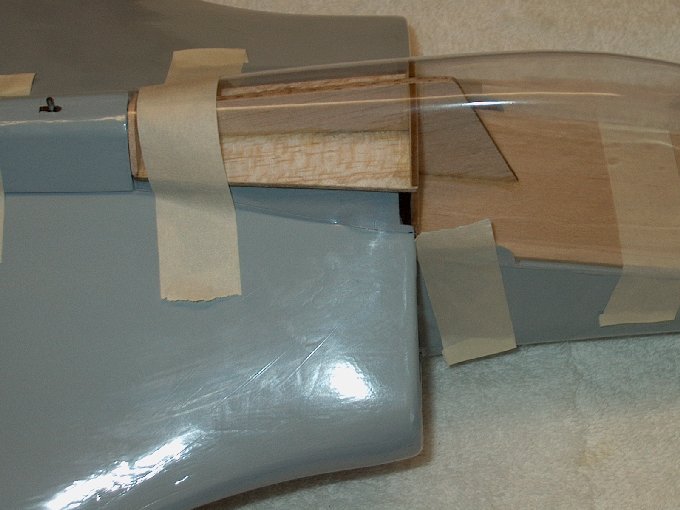
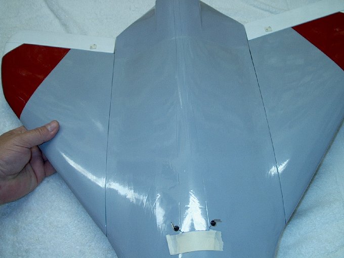
| |
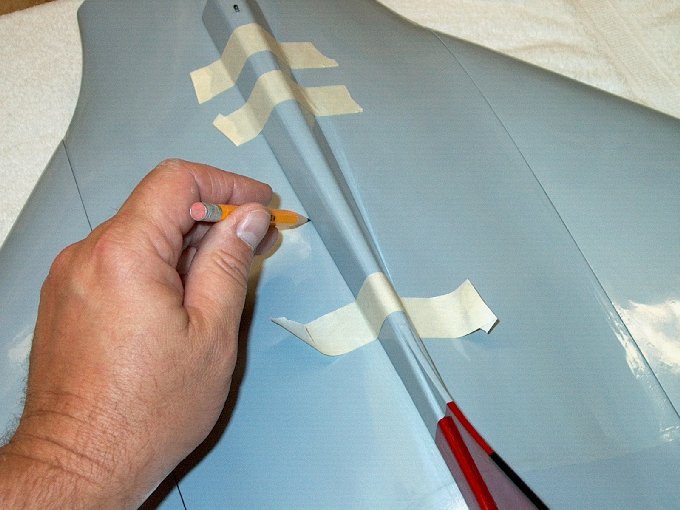
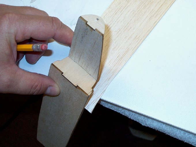
114 - ... and retained
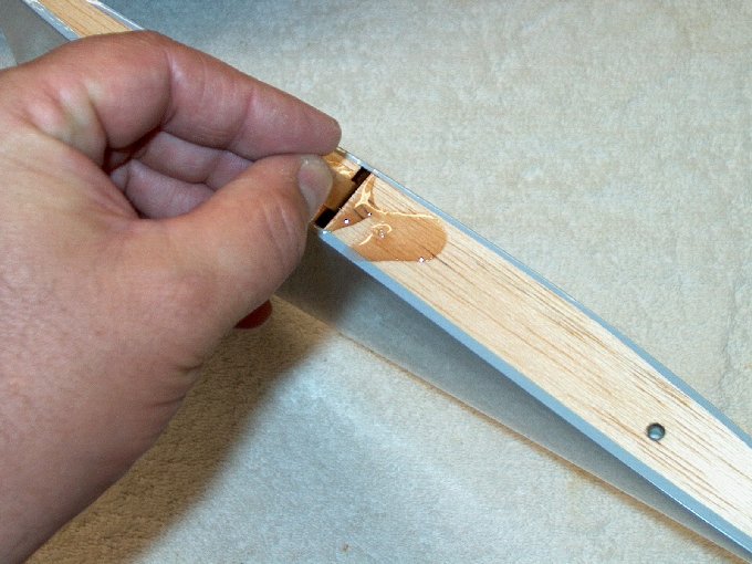
with supplied screw. | |
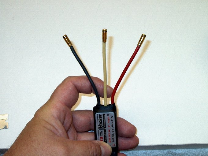
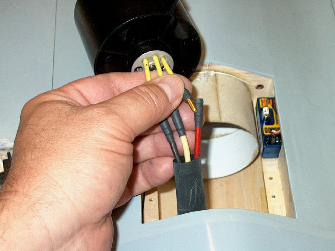
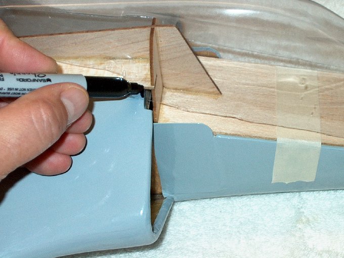
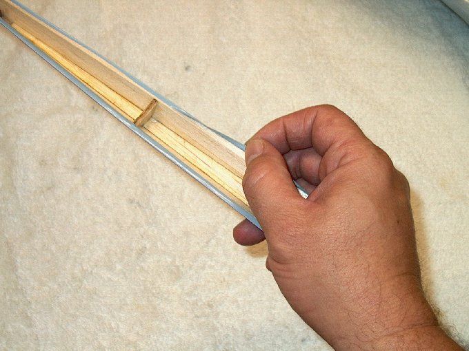
115 - Wiring the motor...
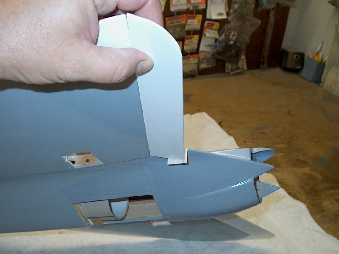
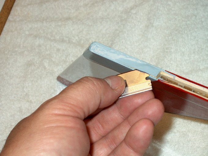
3.5mm connectors added to motor ends.
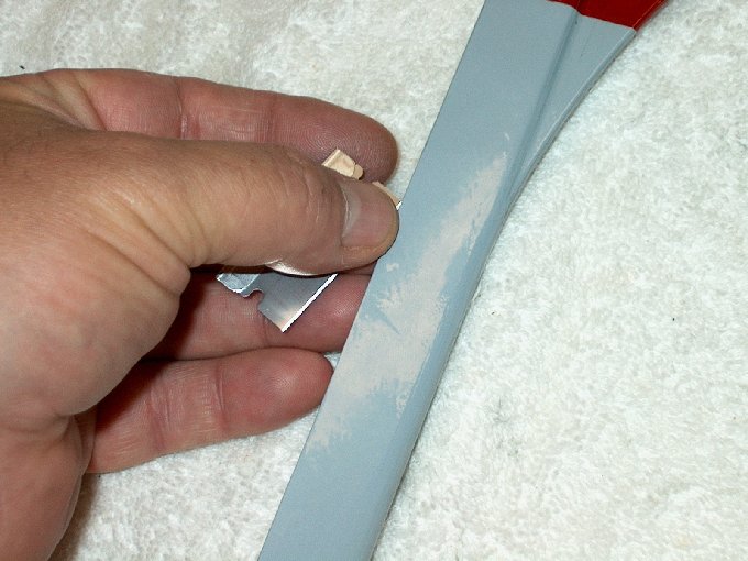
| |
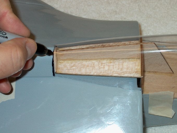
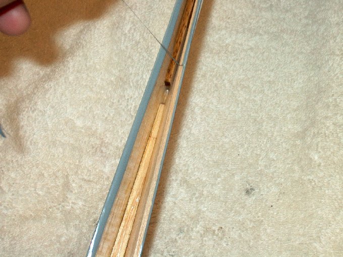
116 - Connectors
installed. | |
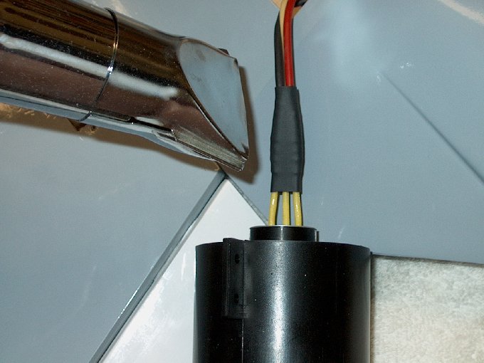
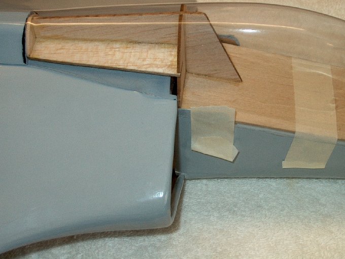
117 - Heat shrink
added. | |
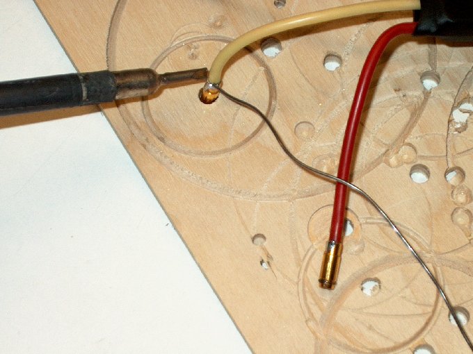
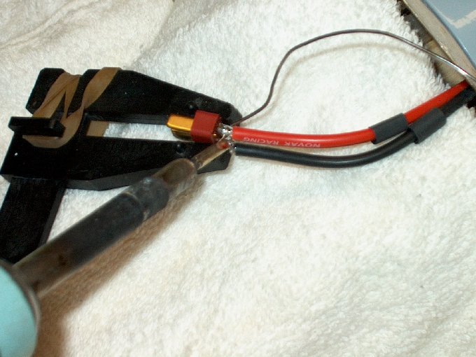
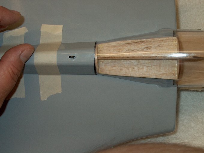
118 - Soldering the
connectors to the electronic speed controller.
| |
119 - Socket connectors
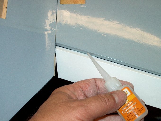
installed. | |
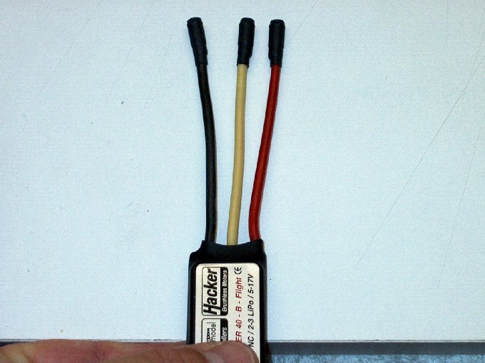
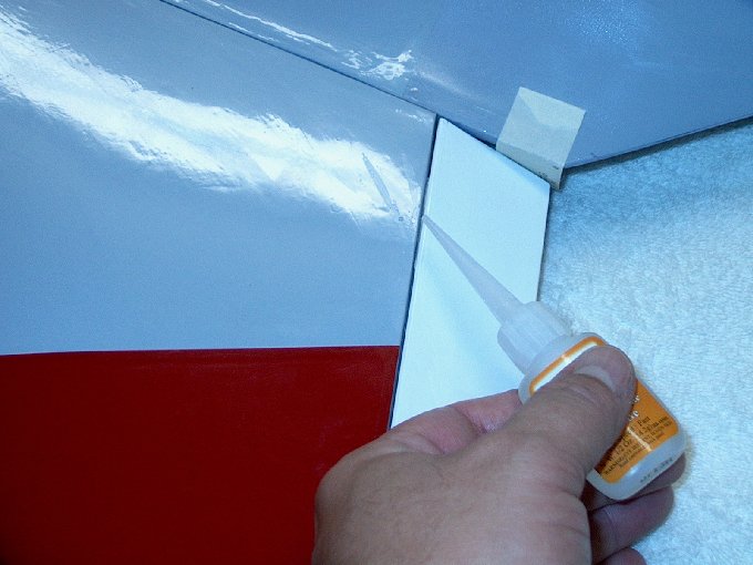
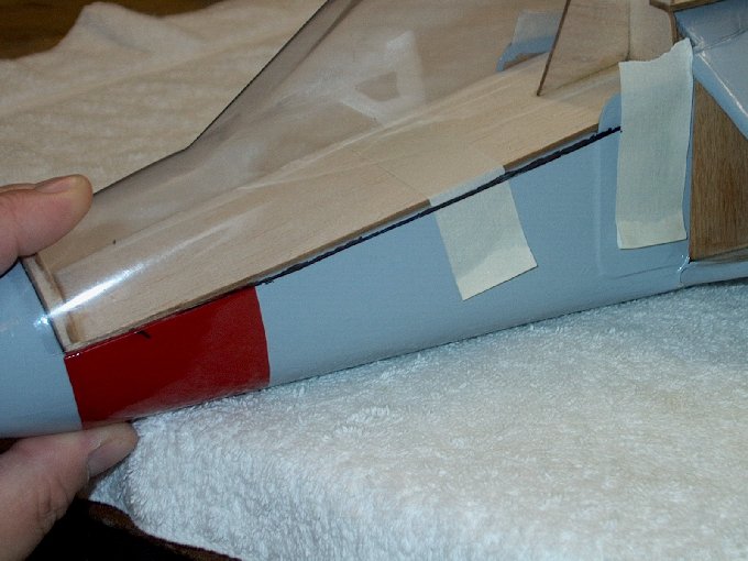
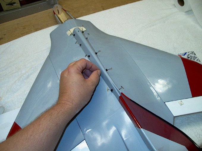
120 - Heat shrink added.
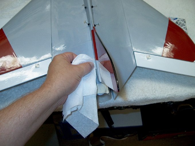
| |
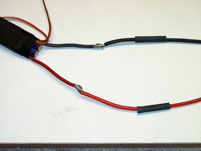
121 - Extended power wires
soldered to the ESC. | |
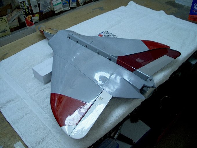
122 - Assembly wired and
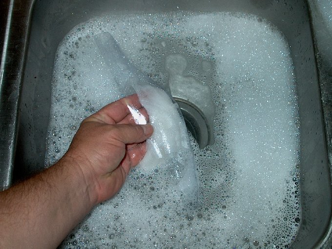
fan balanced prior to installation into airframe.
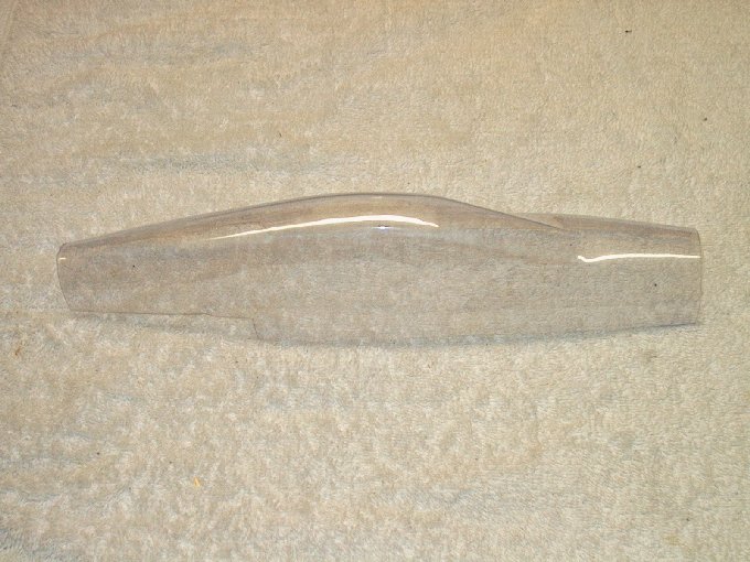
| |
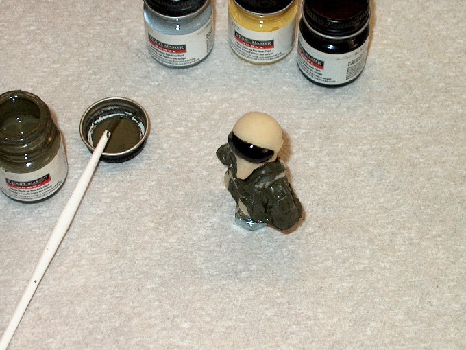
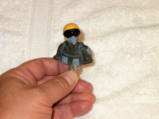
123 - Wings glued and
model ready for color. | |
124 - Hinges removed to
mark them. | |
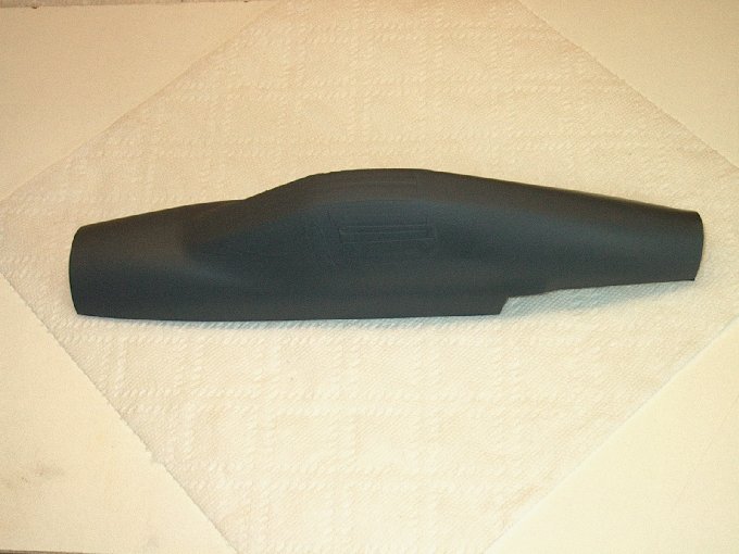
125 - Center lines are
marked down the middle of each hinge
| |
126 - Center lines are
drawn... the lines are drawn up the shorter side, allowing
more surface area to bond when installed.
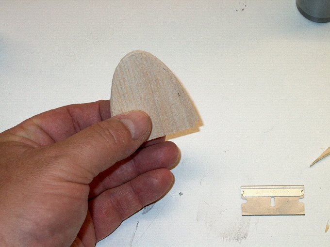
| |
127 - NOTE: THE BUILD
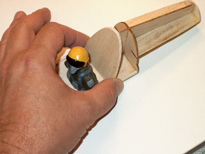
STOPS HERE. The next few steps show my method of dressing up
the model with a bit of color. | |
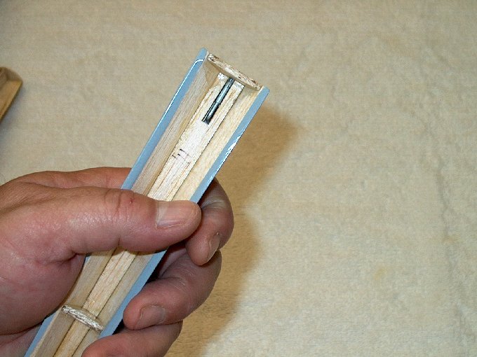
128 - Control surfaces
stripped so I can recover them with white.
| |
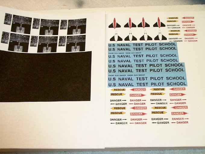
129 - Areas I wanted to
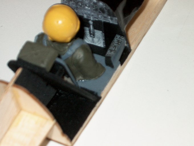
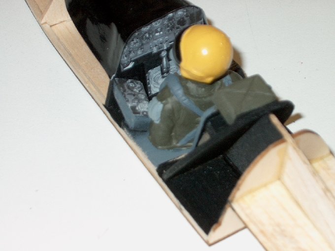
add color to were stripped of the original covering, leaving
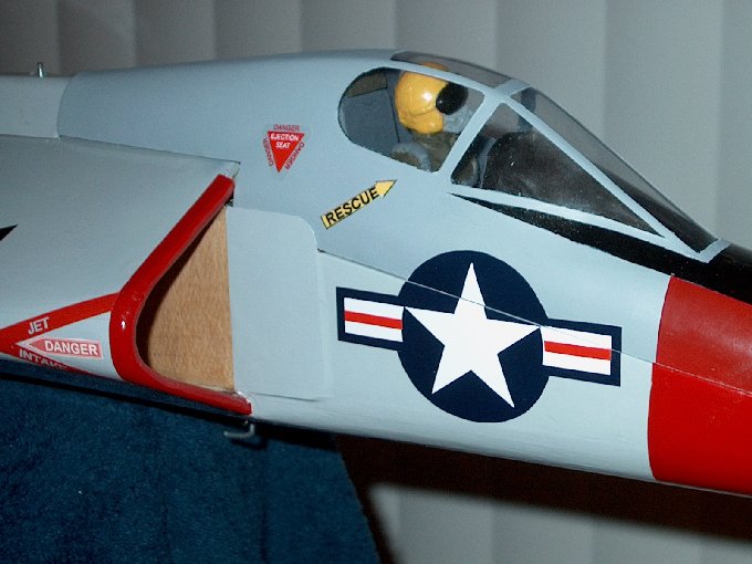
1/8" - 3/16" for overlap. | |
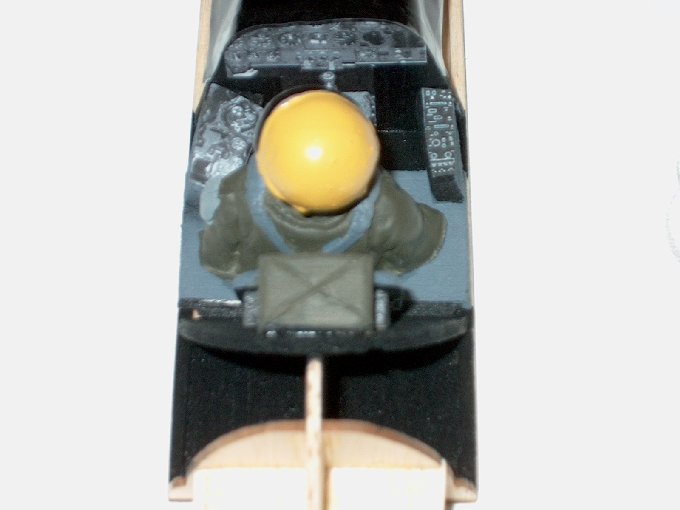
130 - A stripped area
shows some of the quality of build by HET-RC at the
factory. | |
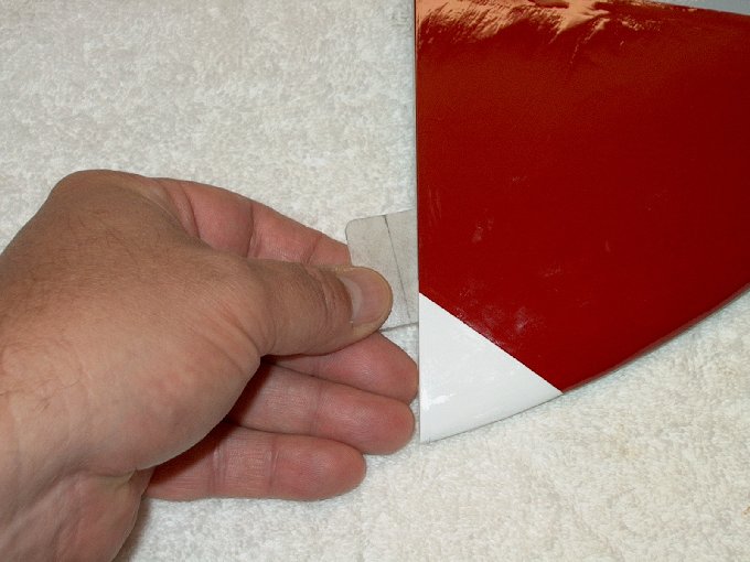
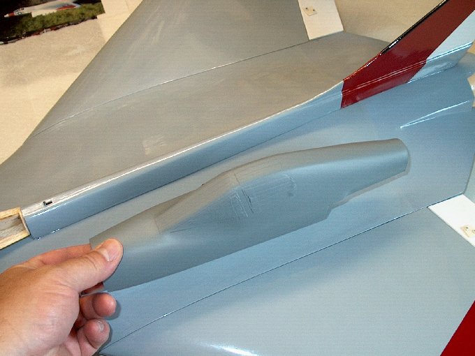
131 - Nose color
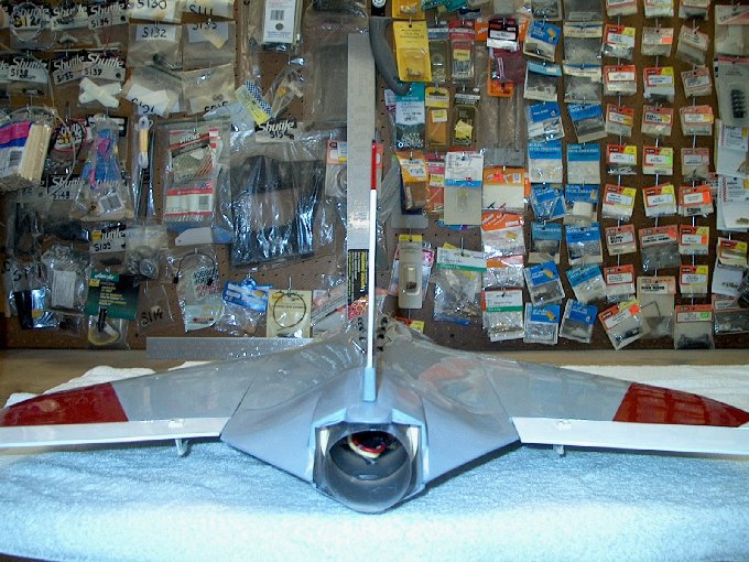
applied. | |
132 - Tail is stripped and
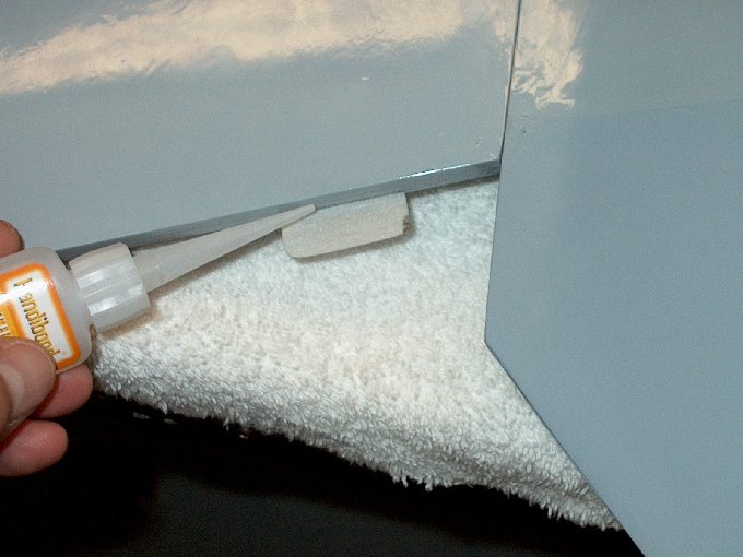
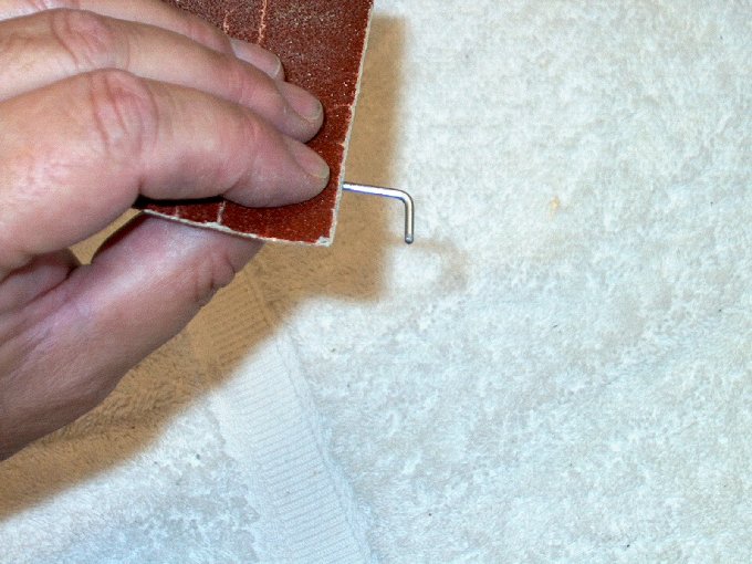
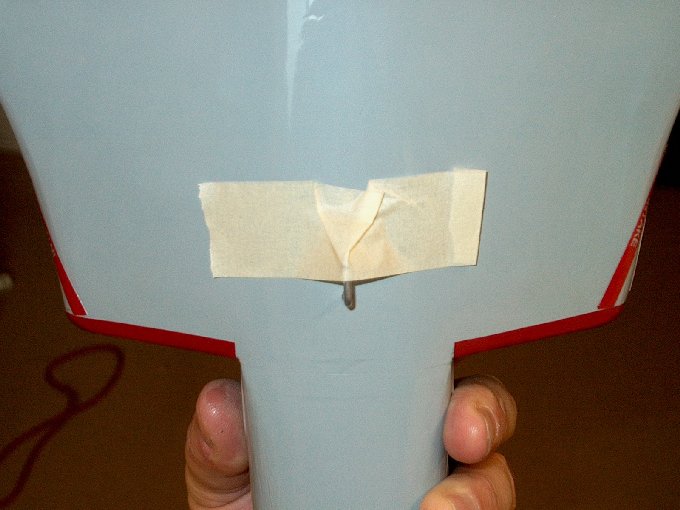
black leading edge added. | |
133 - Red added and being
trimmed before cleanup. | |
134 - Adding some color to
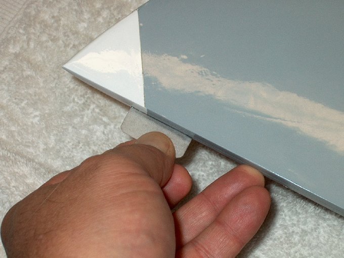
the vertical stab. | |
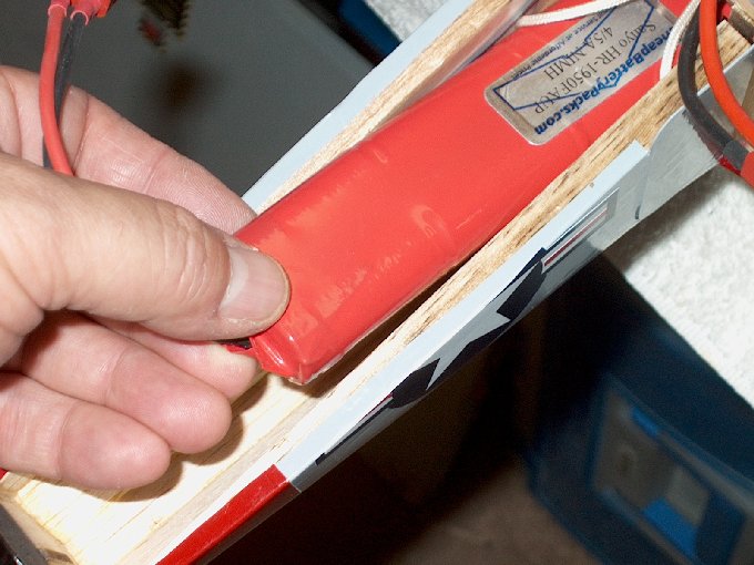
135 - Stab being
ironed. | |
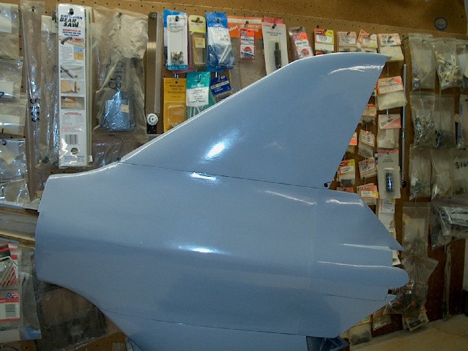
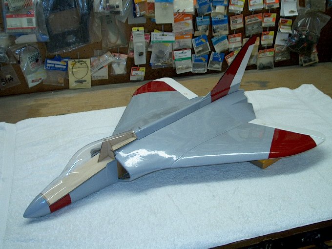
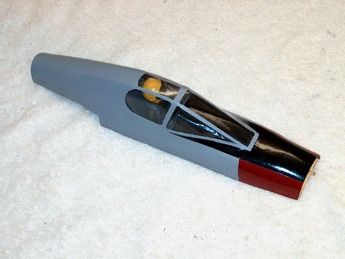
136 - F4D Skyray with the
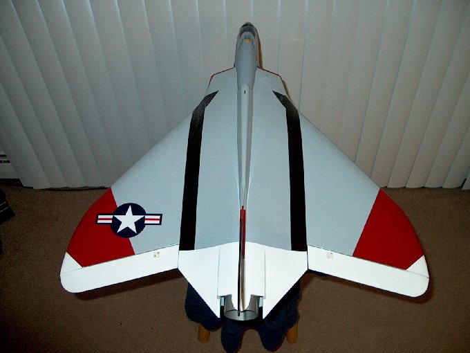
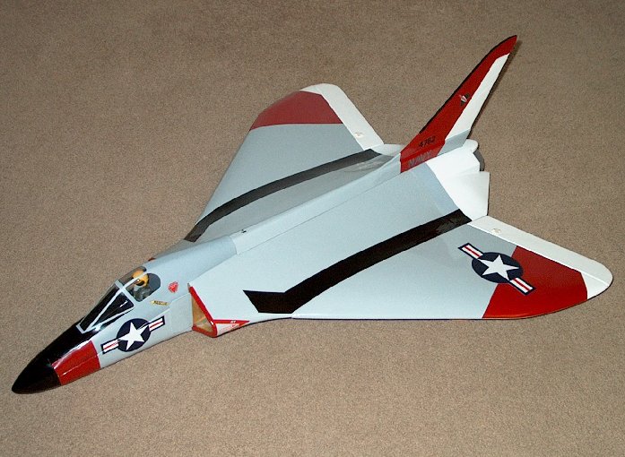
color scheme I decided to use. | |
137 - Skyray covered in
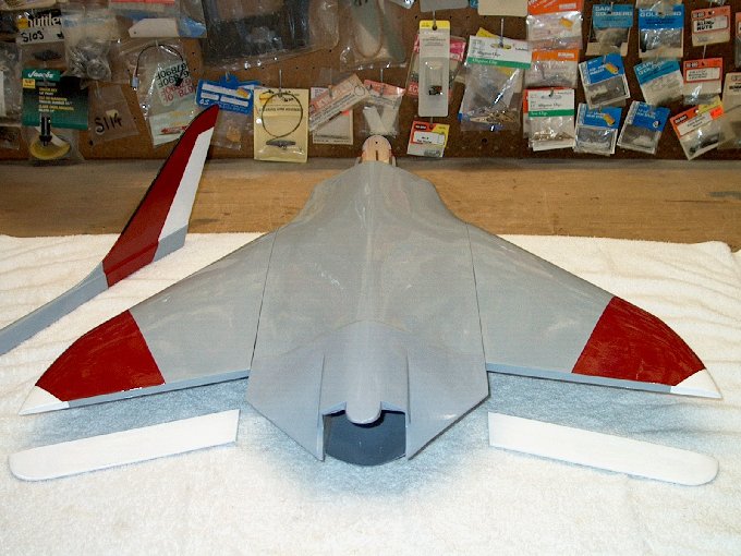
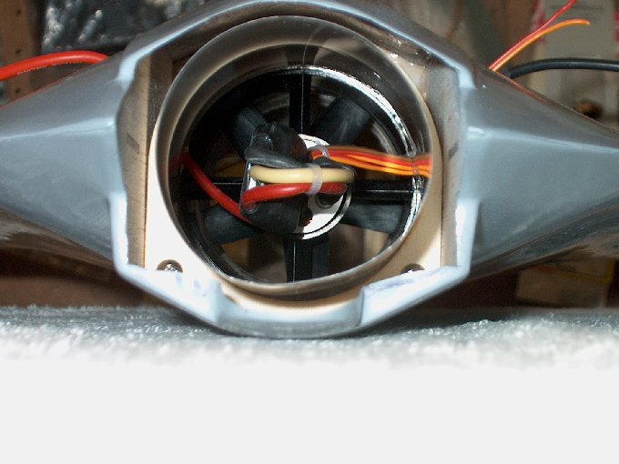
color... NOTE: THE BUILD WILL CONTINUE FROM HERE
| |
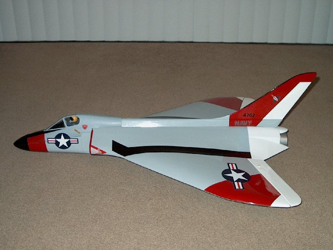
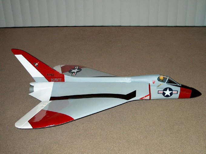
138 - Install a hinge into
the fuselage up to the drawn line. | |
139 - Hinges installed. I
used the control surface to make sure the hinges aligned
correctly. | |
140 - Hinges glued and
tugged to make sure it is in solid.
| |
141 - Hinge glued and
tugged to make sure it is in solid.
| |
142 - Elevon
installed. | |
143 - Other elevon
installed. | |
144 - Make sure it is even
with the wing tip. | |
145 - You should also not
be rubbing the fuselage here at the root.
| |
146 - A piece of masking
tape was marked at center, then 10, 12 and 15mm for down
throw. The stab is designed to throw down only so far.
| |
147 - Holding the stab
with one hand, 5 - 8mm throws are what is called for. I went
to 10 - 12mm so the stab wouldn't bind if pushed a little too
far. | |
148 - Holding the fin
down, thin CA was applied to teach hinge. Make sure the fin is
even with the wing tip because once the CA is applied, it's
too late. | |
149 - Other side of hinge
getting some CA. | |
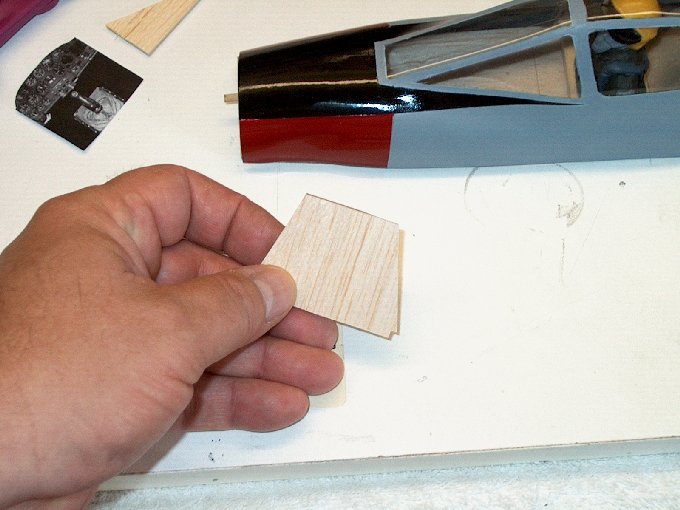
150 - Hinges glued in
place. | |
151 - This step may not be
necessary for everyone. A 3/32" x 1" x 7/16" piece of ply was
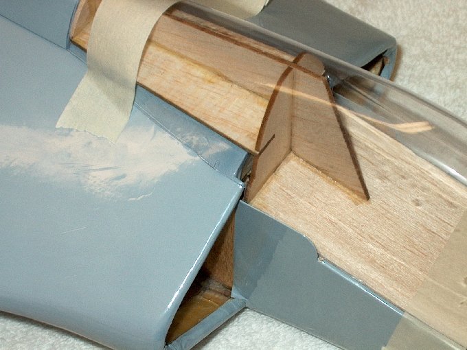
cut from some scrap. | |
152 - Piece glued behind
ply fan mount, extending the mount to the rear former. I plan
on using FAUP's and wanted to make sure I could move the fan
more if needed, so the mount was extended.
| |
153 - 3/8" Balsa triangle
cut to 2 1/4" long. | |
154 - Triangle glued under
the ply fan mounts for support. This was added because the
stock mount was only supported by the 1/2" wide balsa runner
running from the front to the back. This seemed a bit
weak. | |
155 - With this triangle
piece, the runner is now strong and no longer flexes like it
did earlier. | |
156 - Exacto knife used to
shave the rough edges of the duct work.
| |
157 - Another view, you
can see the rough edges on the plastic.
| |
158 - Servos hooked up to
the receiver and both the transmitter and receiver were turned
on so the servos could be centered.
| |
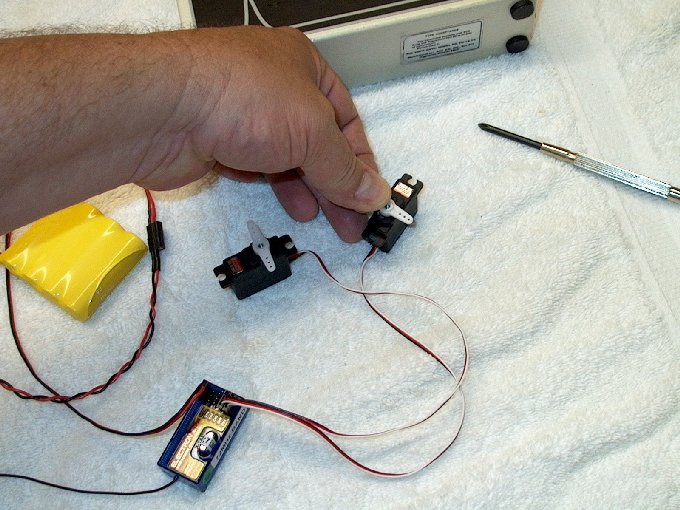
159 - Horns mounted to
servos while they are centered. | |
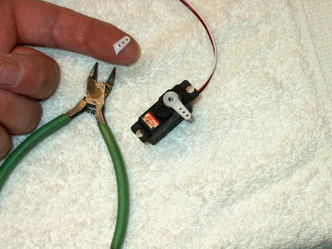
160 - One end was cut off
the horn. | |
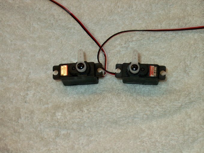
161 - Make sure you do two
opposite servos. | |
162 - Another view showing
mirrored servos. | |
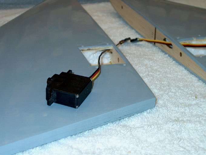
163 - Servo being
installed in left wing. | |
164 - Servo sitting
temporarily in place. | |
165 - Servo wire pulled
through receiver opening, then receiver is prepped for
install. | |
166 - Receiver set in
place. | |
167 - Piece of plastic
tube threaded through other wing. | |
168 - Servo wire taped to
plastic rod... | |
169 - ... and wire pulled
through. | |
170 - Servo can be plugged
in without the use of an extender. | |
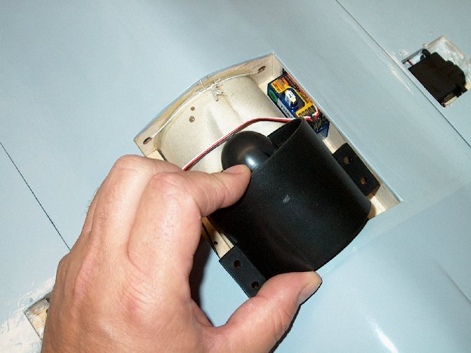
171 - Fan being
installed... you have to bend the cardboard duct down a bit
for the fan to fit. | |
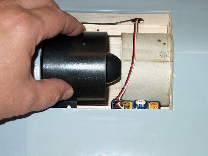
172 - Fan placed in
compartment. | |
173 - Fan unit positioned
over mounting holes. | |
174 - #4 screws and
washers installed. | |
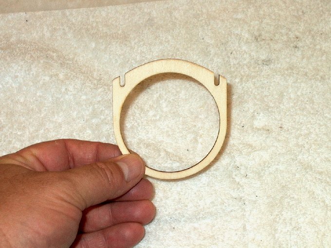
175 - Installing the rear
thrust vector former. | |
176 - The thrust vector
former inserted from the rear. | |
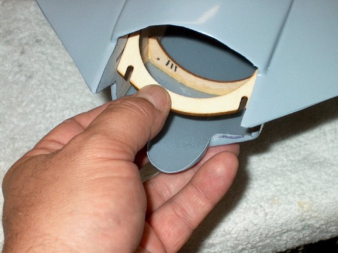
177 - It's pressed flush
against the ply brace behind it. | |
178 - #4 retaining screws
are installed. | |
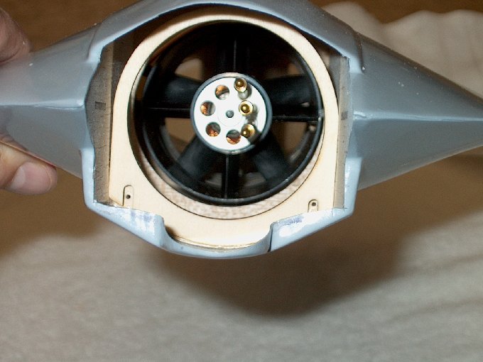
179 - Thrust vectoring
former install completed. | |
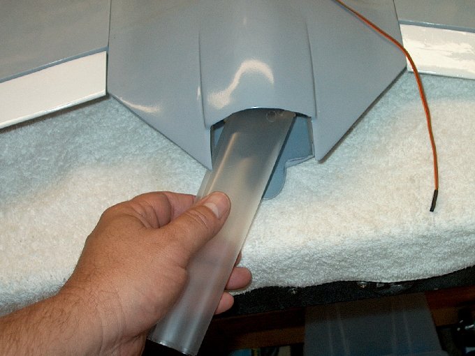
180 - At this point you
can used the supplied paper thrust tube. But I opted to make
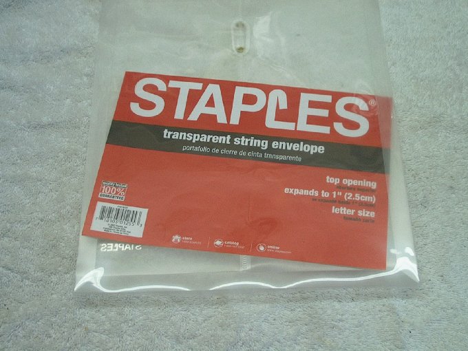
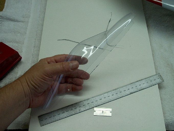
my own. | |
181 - The face of the
plastic folder was removed. | |
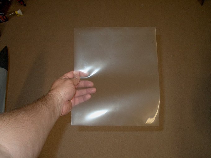
182 - This piece will be
used for the thrust tube. | |
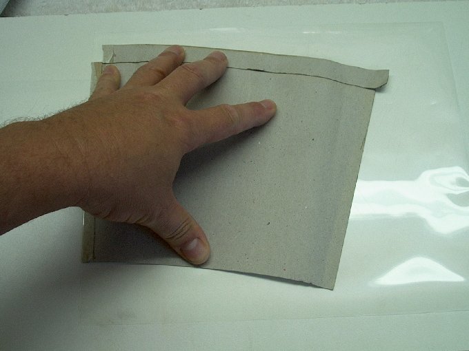
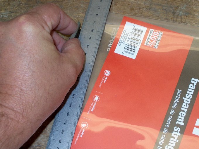
183 - The original tube
was laid flat to draw a pattern. | |
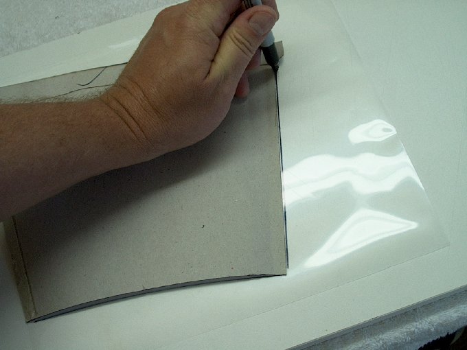
184 - A pattern was dawn
using a marker. | |
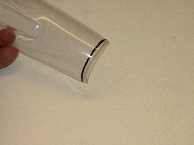
185 - Carefully cut out on
the lines. | |
186 - Thrust tube cut.
| |
187 - The marker was
removed with a paper towel and denatured alcohol.
| |
188 - The trust tube is
ready to roll. | |
189 - The tube was rolled
up and inserted into place. | |
190 - Notches made at the
front to clear the fan mounts. | |
191 - Tube rolled and
packing tape used to seal the edges. Windex was used to get a
bubble free joint. | |
192 - Thrust tube
completed and ready to install. | |
193 - Inserted the ESC
from rear to connect wires. | |
194 - Wires were hard to
reach so fan was removed and ESC was installed.
| |
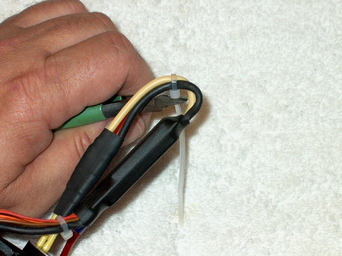
195 - Heat shrink used to
keep the plugs in place. | |
196 - Front of the ESC was
tie wrapped to motor lead. | |
197 - Rear of the ESC
wires tie wrapped to keep them from flying around under
thrust. | |
198 - The fan unit with
ESC reinstalled. | |
199 - Fan unit bolted back
in place. | |
200 - Rear view showing
the ESC in thrust path to keep it cool.
| |
201 - Thrust tube folded
and inserted from rear. | |
202 - The ESC was
maneuvered inside the tube fold. | |
203 - The right side wires
threaded through the punched hole in the tube.
| |
204 - Power wire fed on
the other side. | |
205 - I used this from the
rear like a shoe horn to get the thrust tube on the fan
shroud. | |
206 - Thrust tube slid
forward and has a 3/8" overlap. | |
207 - Packing tape used to
tape the thrust tube to the shroud.
| |
208 - Rear view with
thrust tube installed. | |
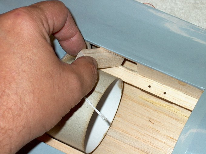
209 - Red power wire fed
through first hole using supplied white string.
| |
210 - A piece of lead
glued to other string which fell out. I had to re-thread it
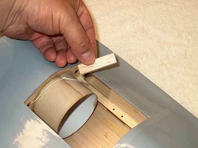
back to the rear. | |
211 - Threading the black
wire. Note that the thread system may work better the other
direction threading from the cockpit rearward, but I already
had soldered my leads to the ESC, so I went this direction.
| |
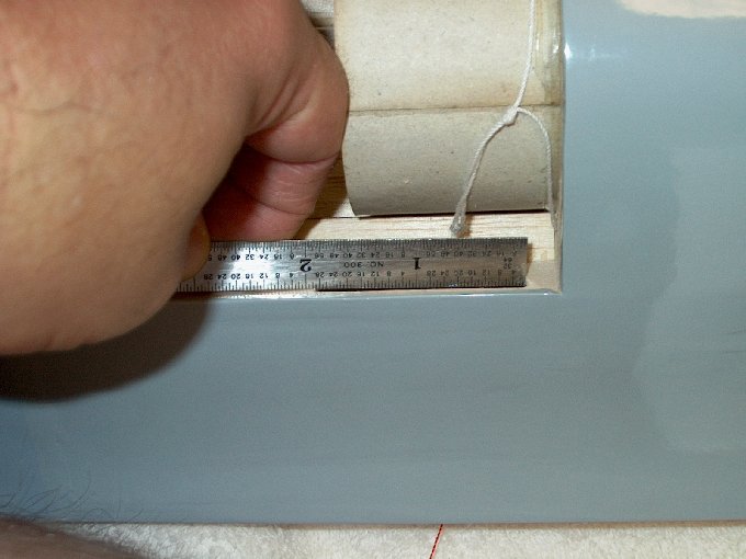
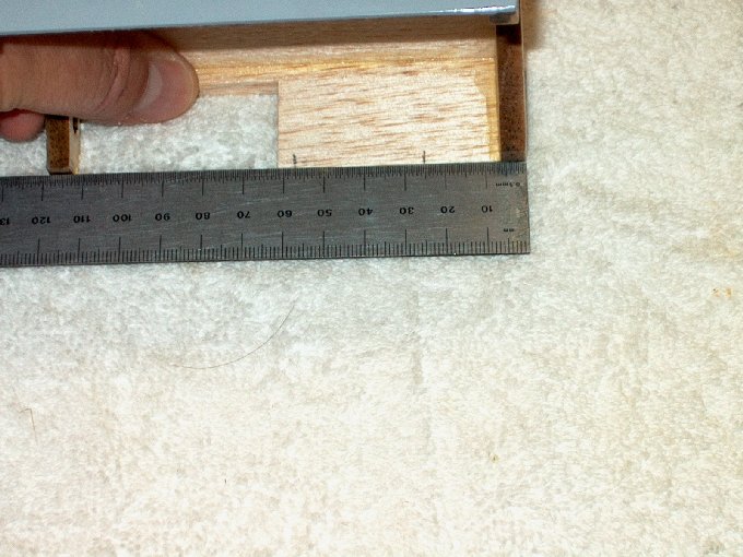
212 - Pulling the black
wire through. | |
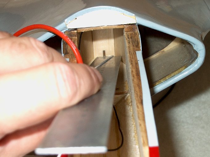
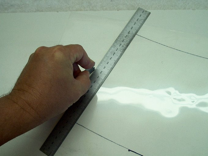
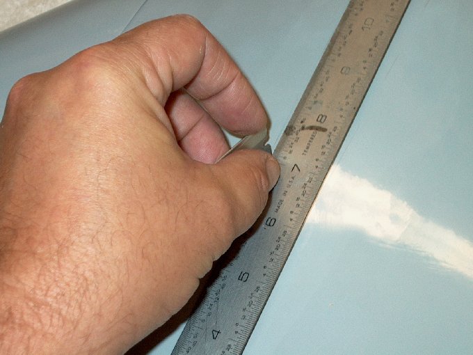
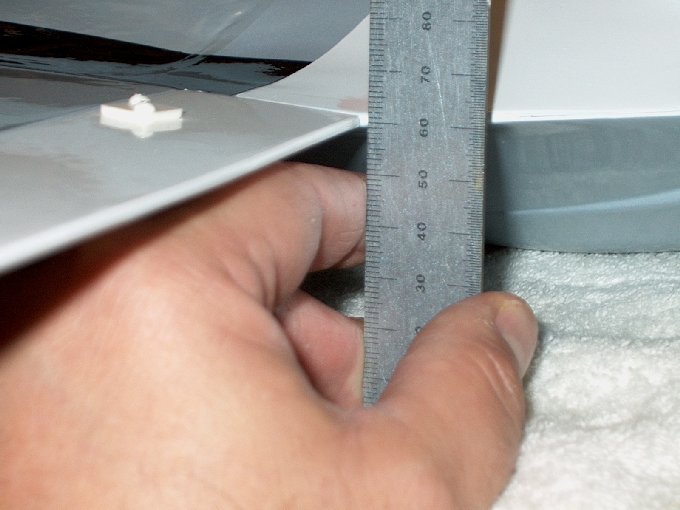
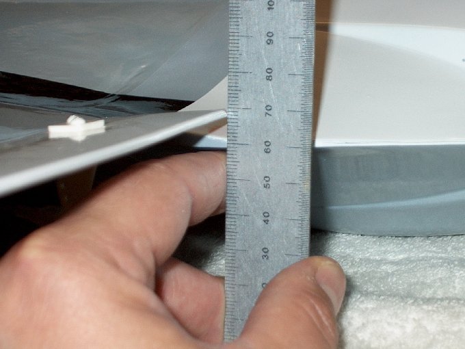
213 - I used a ruler to go
inside above the hole to get pulling leverage upward.
| |
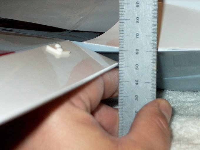
214 - Pulling up got the
wire through the hole... | |
215 - ... and out of the
fuselage. | |
216 - Power wires routed
to battery bay. | |
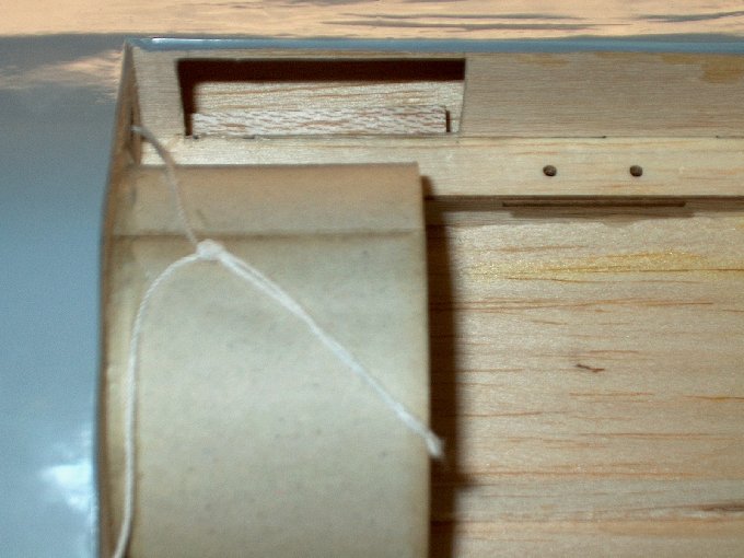
217 - There is a balsa
plate that is a construction helper during the manufacturing
process. It can be removed from the battery area.
| |
218 - Plate snapped out...
you can see where it was glued. | |
219 - Deans Ultra Plug
soldered to the power wires. | |
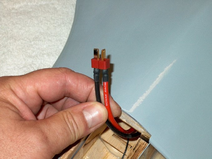
220 - Heat shrink applied
and plug is completed. | |
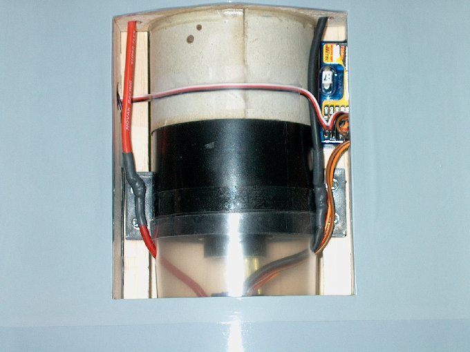
221 - This is the
completed power plant bay. Wires were dressed and Scotch tape
was used to hold down the one servo wire.
| |
222 - Cover was installed
and Scotch tape was used to hold it in place.
| |
223 - Two 1/8" thick ply
plates were cut from scrap to beef up the servo mounting area.
The photo shows one side being soaked in CA to make a smooth
surface for the servo tape. | |
224 - Two plates cut and
surfaces "plasticoated" with CA and sanded smooth.
| |
225 - Plates installed
with epoxy. | |
226 - Servo test fitted
and clearance is fine. | |
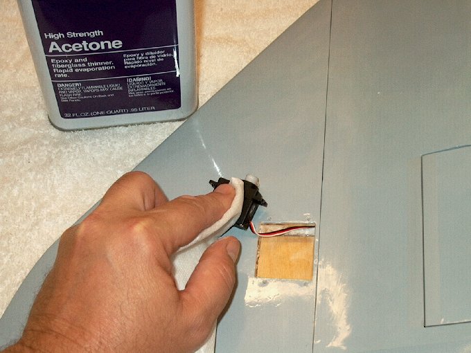
227 - Both servos cleaned
and acetone used prior to adding tape
| |
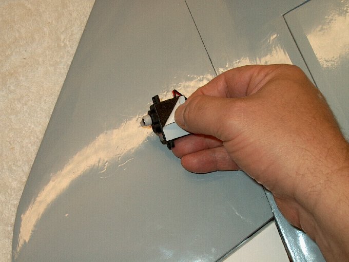
228 - Double sided servo
mounting tape applied and prepped for installation.
| |

229 - Servo
installed. | |
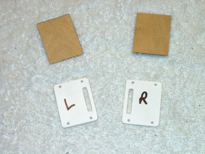
230 - The next few steps
are not necessary, but I wanted to make some color coordinate
servo hatches. | |
231 - Thin 1/32" ply was
used... original hatch was used as a template.
| |
232 - Some left over
covering was used to cover the plates.
| |
233 - Stock plate on left,
new one on the right. | |
234 - Plate installed with
same supplied screws. | |
235 - Both plates
installed. | |
236 - The rest of the
hardware, which will all be used next.
| |
237 - Clevises installed
on rods, along with scrap pieces of fuel line.
| |
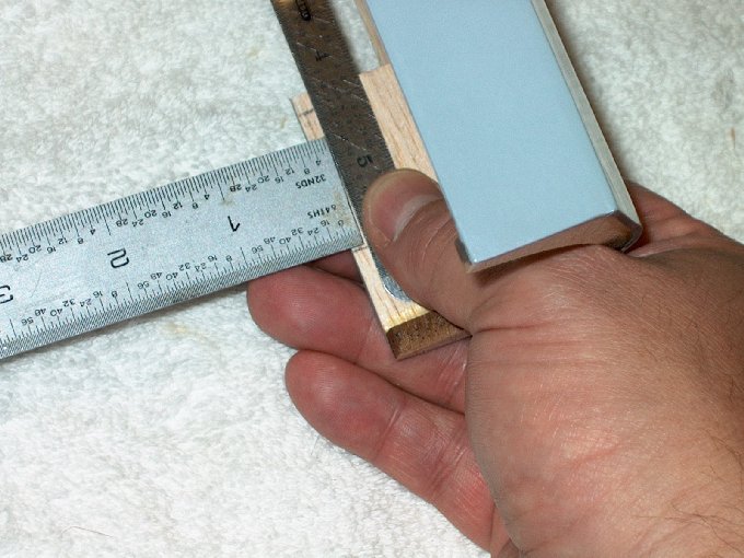
238 - Ruler used for
alignment and first hole marked. | |
239 - Picture shows
alignment for proper elevon horn location.
| |
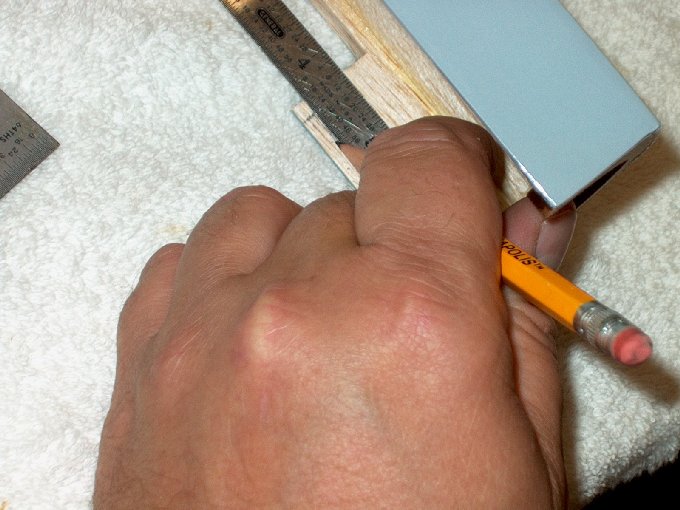
240 -Elevon
drilled. | |
241 - Bolt added and
second hold drilled. | |
242 - Retainer plate held
on other side as bolts were tightened.
| |
243 - Excess bolt length
cut off. | |
244 - Horn installed.
| |
245 - Rod installed...
| |
246 - ... and radio turned
on to center servos. | |
247 - Clamp used to hold
elevon at center. | |
248 - Wire bent at servo
horn. | |
249 - Z-Bend made and wire
installed. | |
250 - Wire made for other
side... note the servo horn holes needed to be drilled a bit.
| |
251 - Other side
installed. | |
252 - Preparing to install
the vertical stab. | |
253 - Cockpit installed
and centered over rear area, then taped to hold it in place.
| |
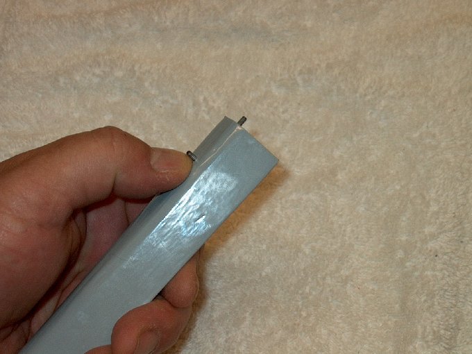
254 - Hatch latch
extended. | |
255 - Latch installed into
rear of cockpit. | |
256 - Masking placed on
tail, then a mark was made at the center
| |
257 - Trimming the
canopy... it has been rough cut with scissors.
| |
258 - Time to fit it to
the cockpit. | |
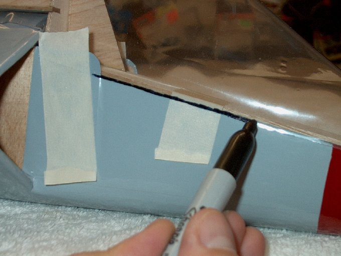
259 - Permanent marker
used to mark trim lines. | |
260 - Length is marked in
the rear. | |
261 - Top view shows marks
made in rear. | |
262 - Fuselage to nacelle
joint needs some fitting. | |
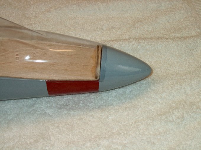
263 - Nose is too long and
needs trimming. | |
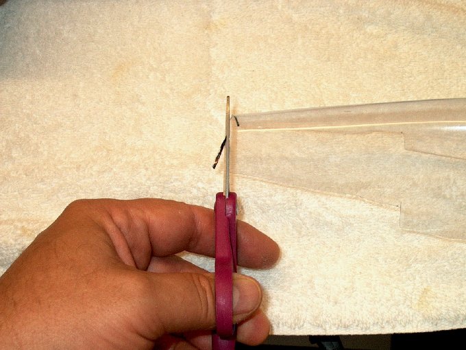
264 - Trimming the rear...
I worked from the rear forward to fit the canopy.
| |
265 - Rear fits
well | |
266 - Next, the sides were
marked to trim to the deck. | |
267 - Rear of the canopy
was anchored with tape. | |
8 - Picture shows side
marked to trim. | |
269 - Sides were trimmed
at the lines. | |
270 - A ruler was used to
steady the cut. | |
271 - Trim
finished. | |
272 - Canopy taped down
again and corner checked for fit once more.
| |
273 - The front of the
canopy marked to trim. | |
274 - Ready to cut.
| |
275 - Trimming the
front... canopy fitting completed. | |
276 - Preparing to epoxy
the vertical stab. Rear of stab centered using mark made on
tape from previous steps. | |
277 - Assembly taped in
place and pencil used to make a mark on the fuselage.
| |
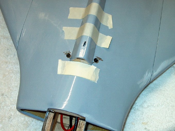
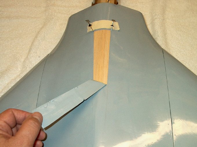
278 - Layers of tape were
stacked up front as a point to but the assembly up against.
Two pins were used to mark sides. | |
279 - Tape that was used
to anchor the front of the vertical stab during canopy
trimming was removed from the front of the stab. The stab was
removed, showing the pencil mark made earlier.
| |
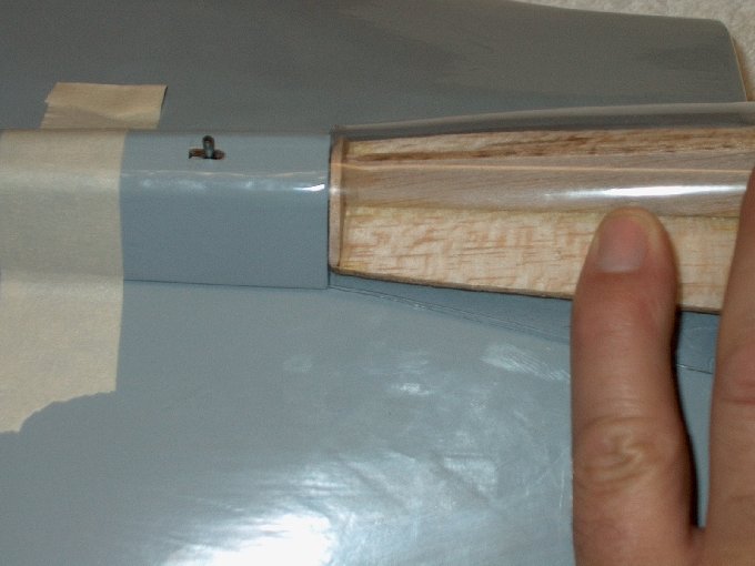
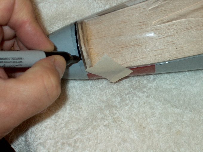
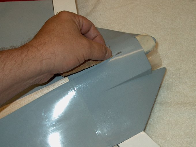
280 - Bottom of stab
needed excess covering removed so epoxy would adhere to the
wood underneath. | |
281 - Holding the razor
like this allowed me to judge the depth and width of the
cut. | |
282 - Excess covering
being removed. | |
283 - Rear also cut away
so it could be epoxied. | |
284 - Area that was
trimmed is ironed back down. | |
285 - Stab ready for
epoxy. | |
286 - Fuselage stab area
ironed down before cutting. | |
287 - Area being trimmed.
| |
288 - Removing the excess
covering. | |
289 - Rear area is plastic
and was roughed up with 100 grit sandpaper for good glue
adhesion. | |
290 - Fuselage ready for
epoxy. The expose area had epoxy applied lightly with a brush.
| |
291 - Epoxy was applied to
the bottom of the vertical stab assembly, then placed flush
against the front tape and pinned in place.
| |
292 - Stab was checked to
be vertical, then excess epoxy was removed.
| |
293 - Stab pinned and
drying. | |
294 - The fin was checked
for vertical alignment once more, then left to set.
| |
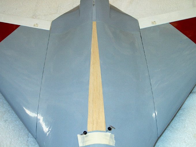
295 - Pins removed,
vertical stab assembly is completed.
| |
296 - Canopy washed in hot
soapy water to remove any release agents.
| |
297 - Canopy dried and
ready for paint. | |
298 - Painting the
pilot... sunshield was glazed with epoxy prior to painting it
black. | |
299 - Pilot painted and
ready to fly. | |
300 - Masking the canopy.
| |
301 - Ready to paint.
| |
302 - Canopy primed.
| |
303 - Canopy
painted. | |
304 - Color didn't
match... I spent all day trying to find a matching color and
stripped it twice to repaint. | |
305 - Final paint.
| |
306 - masking removed...
it's going to do ok for now. | |
307 - Working on the
cockpit... the edges were thickened up with another layer of
3/32" balsa. | |
308 - making a cockpit
back. | |
309 - Back made and
shaped. | |
310 - Cockpit back in
place... time now to make a seat. | |
311 - Canopy finally
painted. | |
312 - Detailing the
cockpit. | |
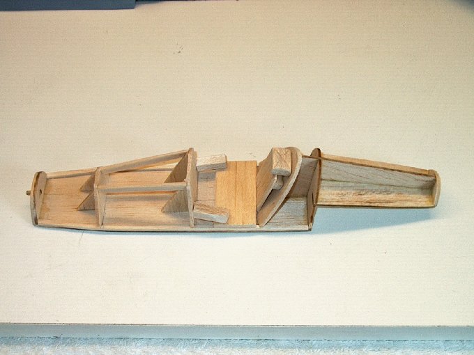
313 - Here is the
framework for the cockpit. | |
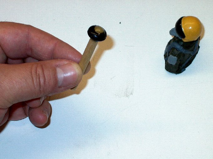
314 - A rubber grommet was
epoxied to the dowel, then it was inserted into the figure's
head. The figure could then be attached to the cockpit by
gluing in the dowel at the base with epoxy.
| |
315 - Much of the time
today was spent making some decals that are unique to this
model. | |
316 - Pilot inserted into
the cockpit. | |
317 - View of the other
side. The dash panel is an exact replica taken from a photo of
a real F4D cockpit. It took a couple hours with the Paint Shop
program to do the "Dash". | |
318 - Top view showing
most of the cockpit. | |
319 - View with the canopy
in place. | |
320 - Canopy epoxied to
cockpit with 15 minute epoxy and left to set.
| |
321 - I decided to cover
the intakes with the correct color for my scheme.
| |
322 - Close up of the area
re-covered... not an easy job, but it was a good challenge.
| |
323 - Cockpit epoxied and
finished. | |
324 - Gluing the hook into
place with 15 minute epoxy. | |
325 - Roughing up the tow
hook for good glue adhesion. | |
326 - Gluing the hook into
place with 15 minute epoxy. | |
327 - Tow hook taped with
epoxy. | |
328 - Tow hook
installed. | |
329 - Installing the
battery with velcro. | |
330 - Once the battery was
installed, it needs to be balanced at 100mm from the front of
the wing joint... I made marks with a marker to note the CG
location. | |
331 - Setting the
throws... recommended throws are 5mm up and 5mm down for both
aileron and elevator. | |
332 - I set mine at 8mm up
with 5mm set as low rates. | |
333 - The same goes for
down... set at 8mm with 5mm used for low rates.
| |
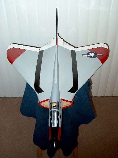
334 - Here's a look from
the front. | |
335 - View from the
rear. | |
336 - The left side...
| |
337 - Rights
side... | |
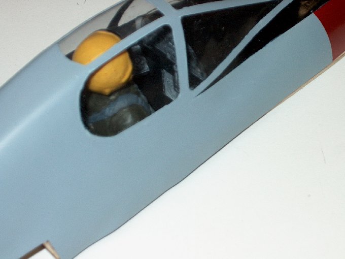
338 - Close up of the
cockpit area. | |
340 - The HET-RC F4D Skyray EDF Jet
| |

This Website and all documents herin are Copyright © 2012 www.scalerocketry.com -
All rights reserved.
| |