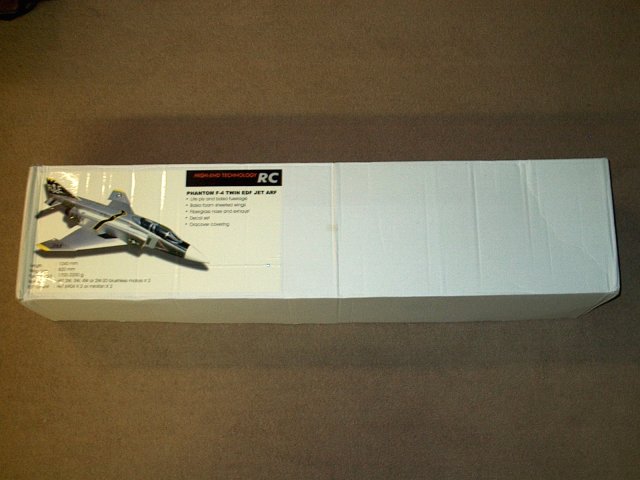
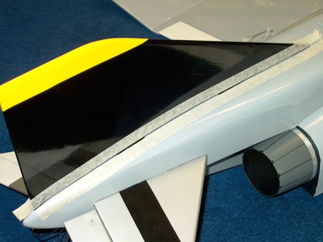
The HET-RC F-4 Phantom Twin Minifan EDF as
it comes from Markos at Warbirds-RC
| |
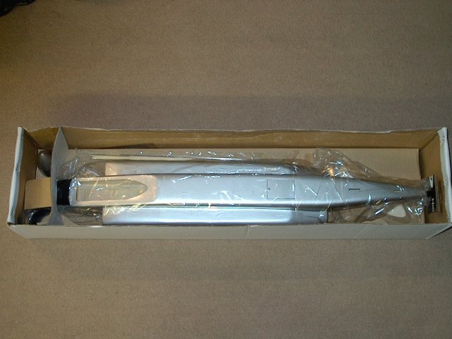
Opening the box reveals a well packed and
rather large model | |
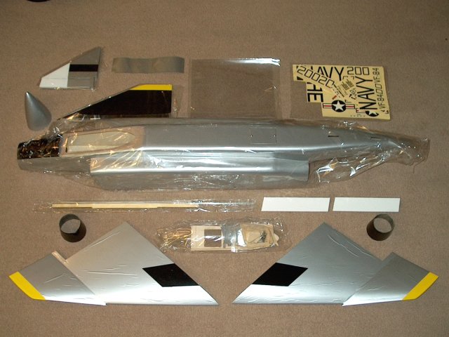
Every that comes with the ARF is shown
| |
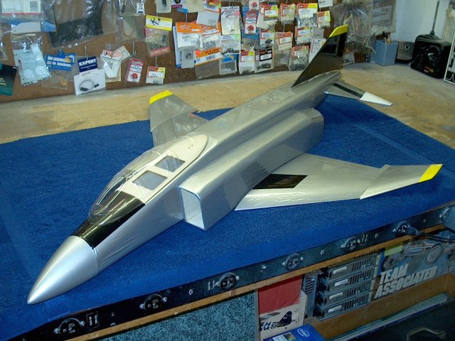
The F-4 Phantom assembly
| |
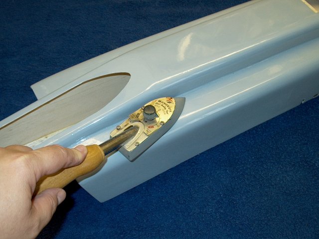
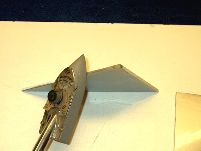
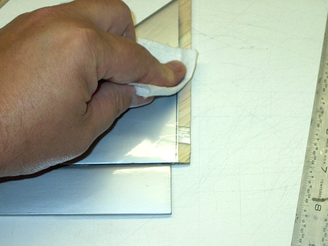
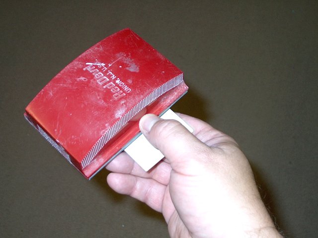
You should use an iron to remove any
wrinkles in the finish | |
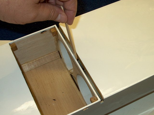
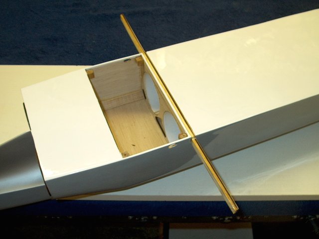
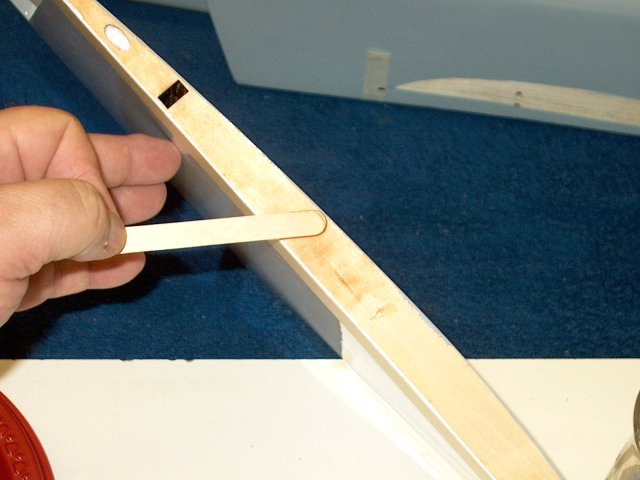
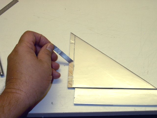
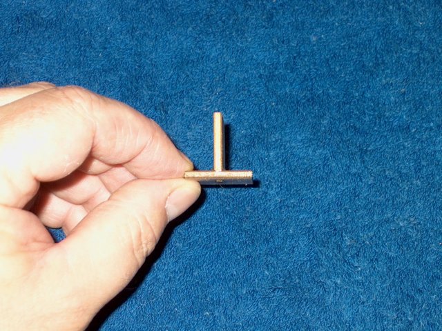
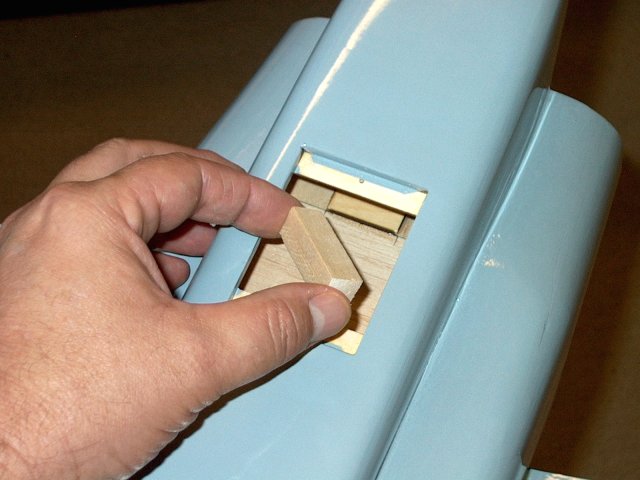
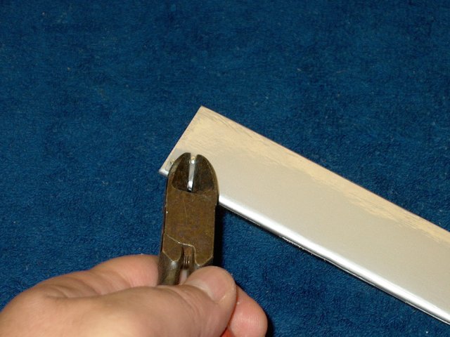
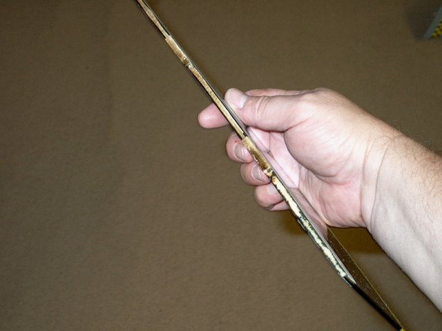
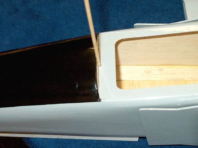
The main spar is the first piece to be
installed | |
Dry fit the spar in place as shown, with
the cut out sides pointing to the bottom side of the
fuselage(pointing up in pic.) Also check for a slight bow in
the spar; if present, install the spar so the outer ends bow
toward the front of the fuselage | |
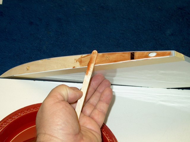
Epoxy is applied to center of the spar
right up to each notch | |
Apply epoxy to the slot sides where the
spar will be installed | |
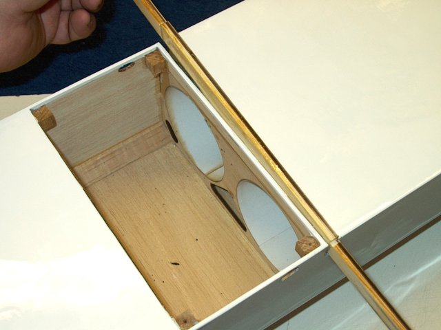
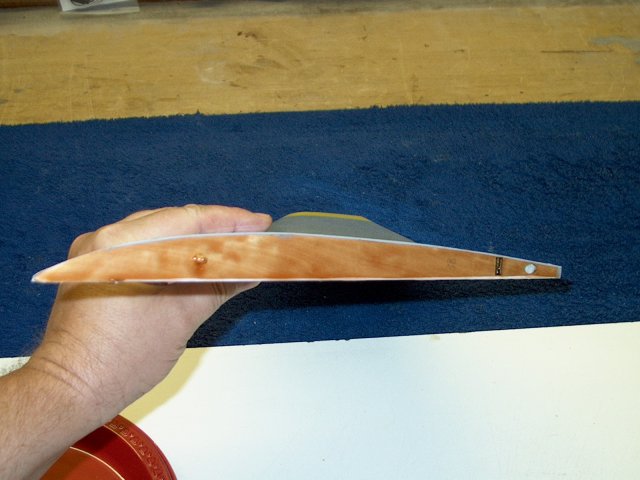
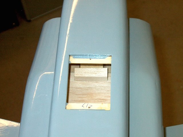
Install the spar as shown, noting cutouts
in spar and position so the spar is centered and they are
flush at each side of the fuselage | |
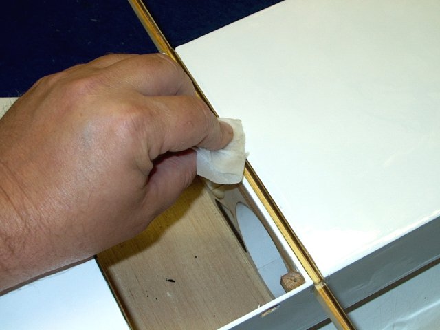
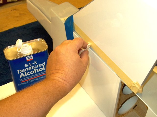
Wiped off any excess epoxy with denatured
alcohol and a paper towel | |
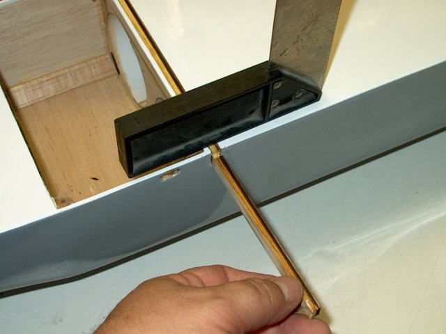
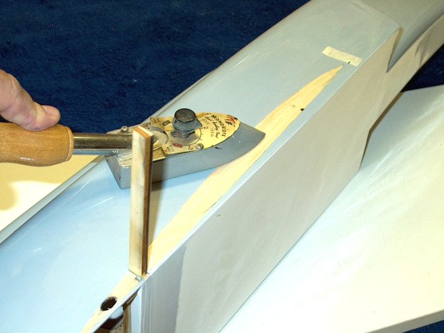
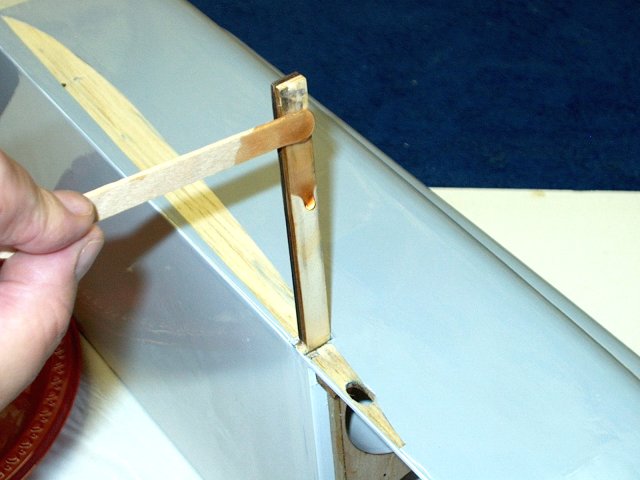
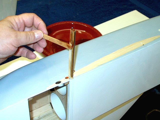
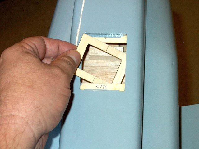
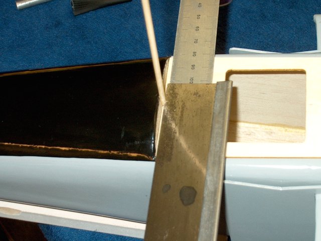
A square is placed across the joint while
the glue is still wet and the spar is pulled up on each side
so it is flush to the bottom of the fuselage
| |
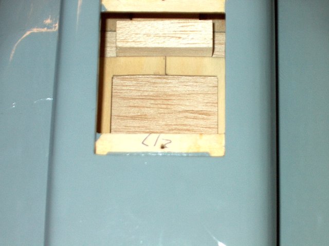
Once the spar is installed correctly, then
centered and adjusted flush, allow the epoxy to set
| |
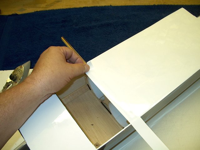
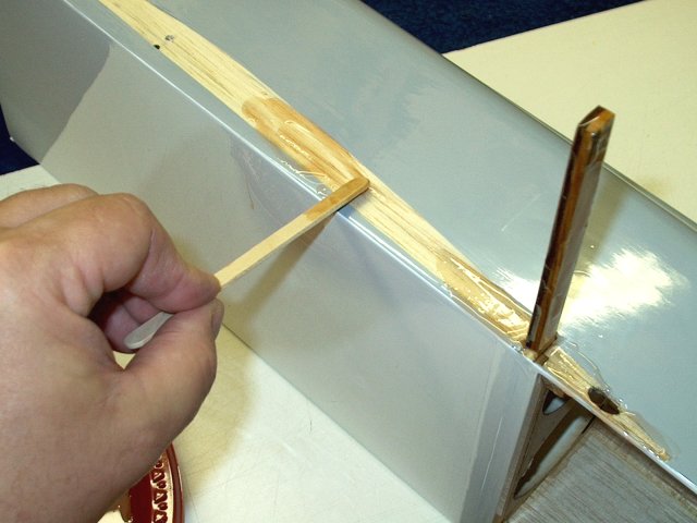
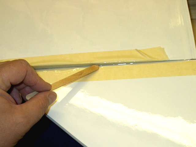
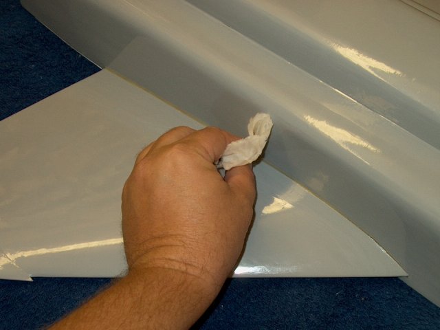
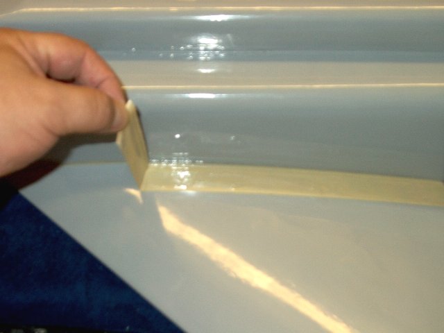
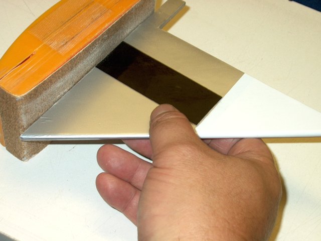
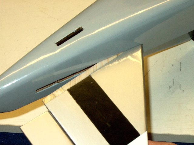
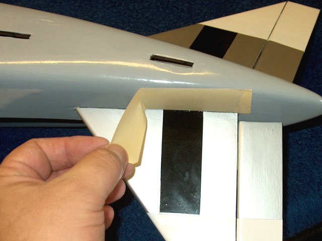
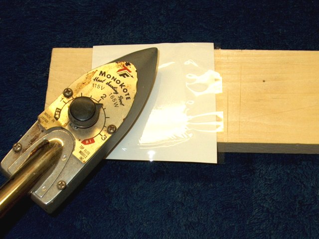
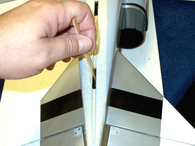
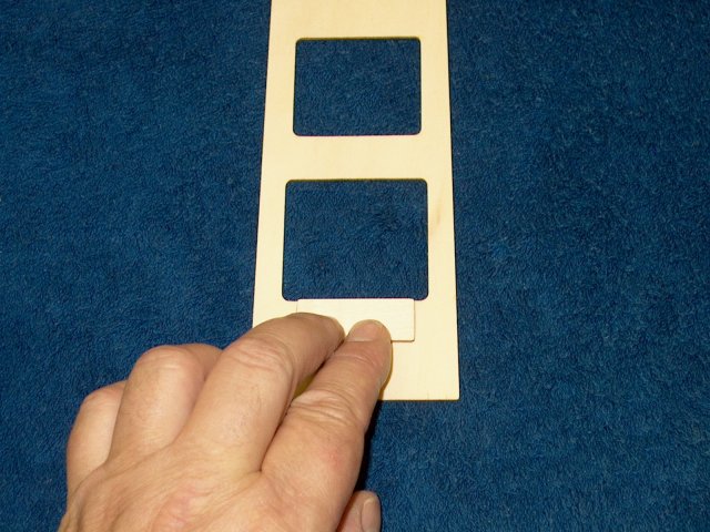
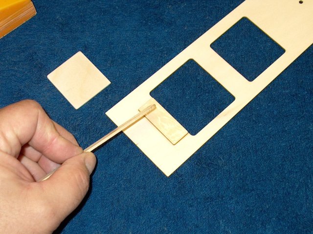
A strip of covering material supplied in
the kit is used to cover the slot. Note that the model was
recovered in the pics to a different color, so the colors may
not match your kit, but the procedures are the same
| |

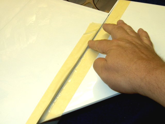
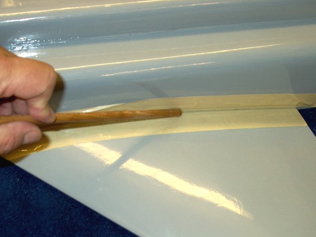
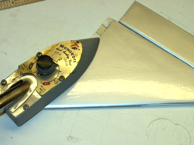
A hobby iron is used to install the strip
of covering | |
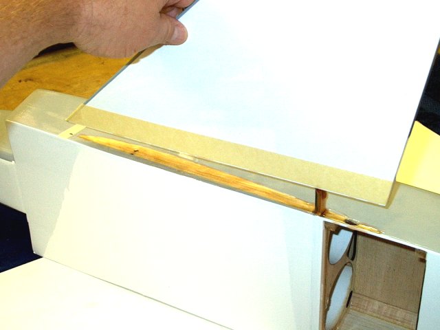
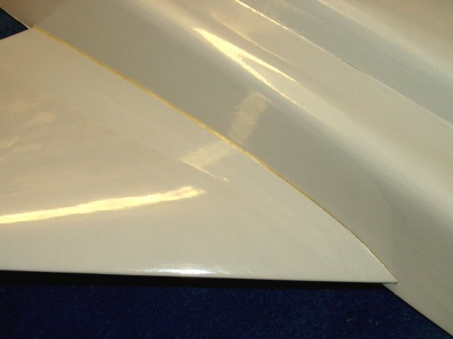
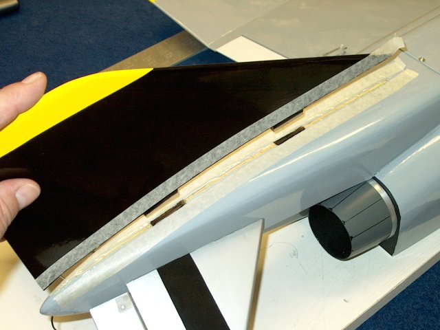
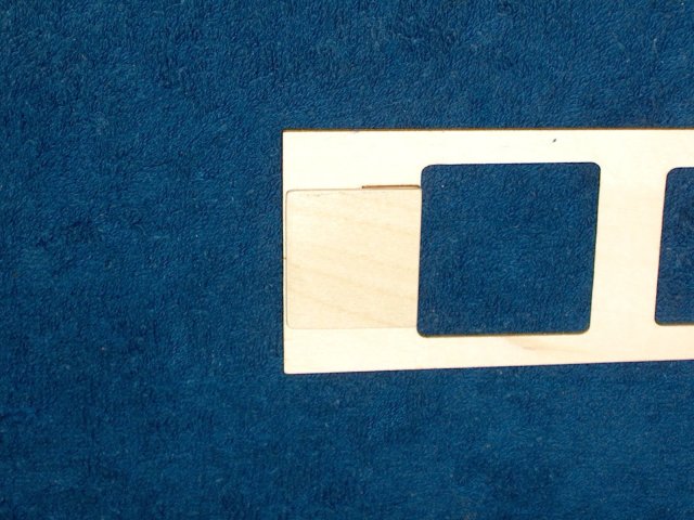
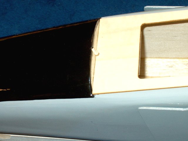
Main Spar assembly is shown completed
| |
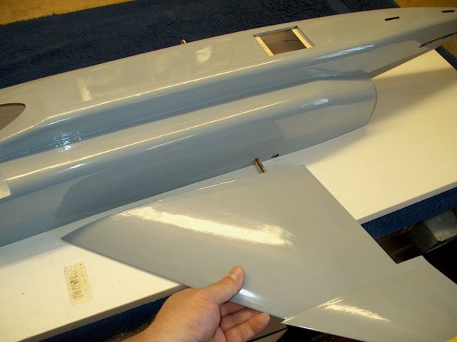
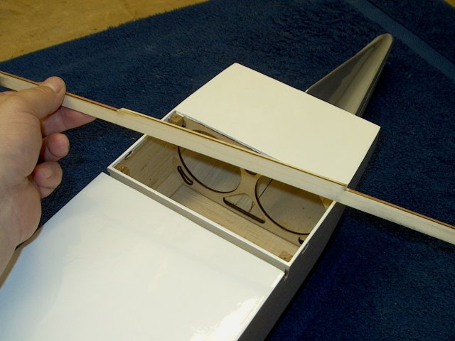
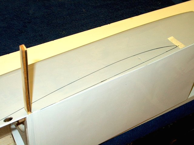
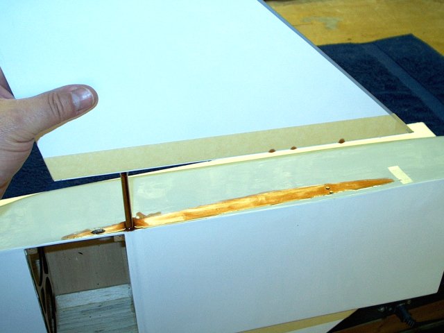
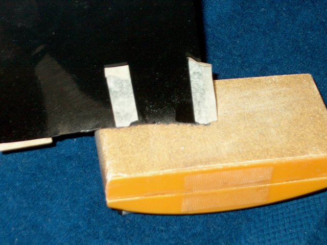
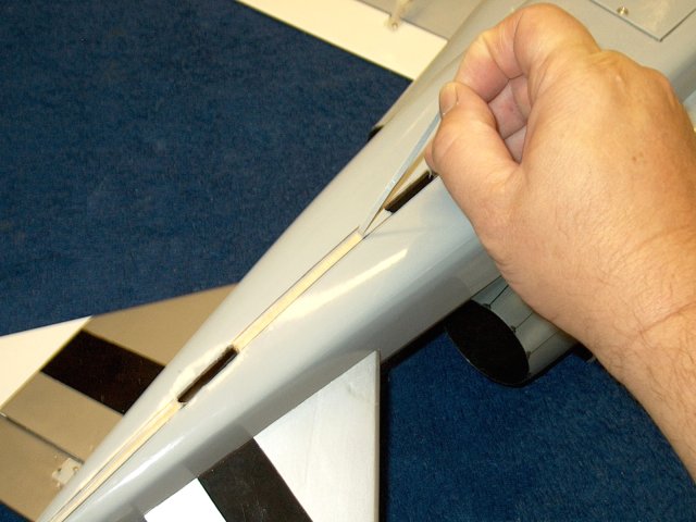
Temporarily slide a wing on the spar
| |
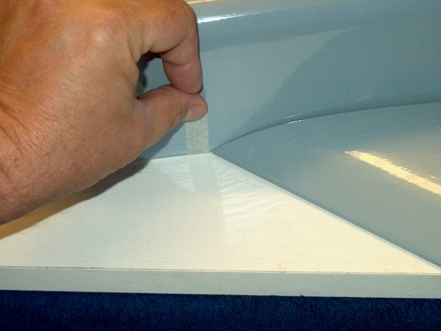
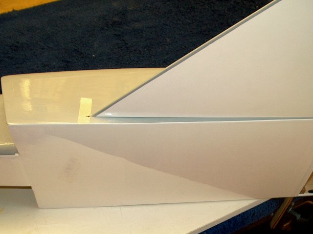
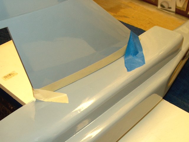
Apply a piece of tape just in front of the
leading edge of the wing | |
Install the other wing and apply another
piece of tape for it | |
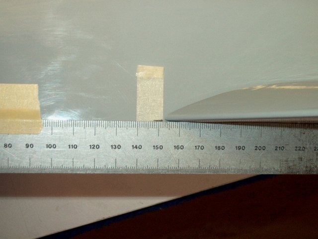
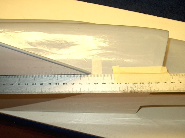
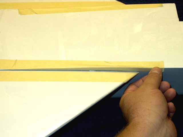
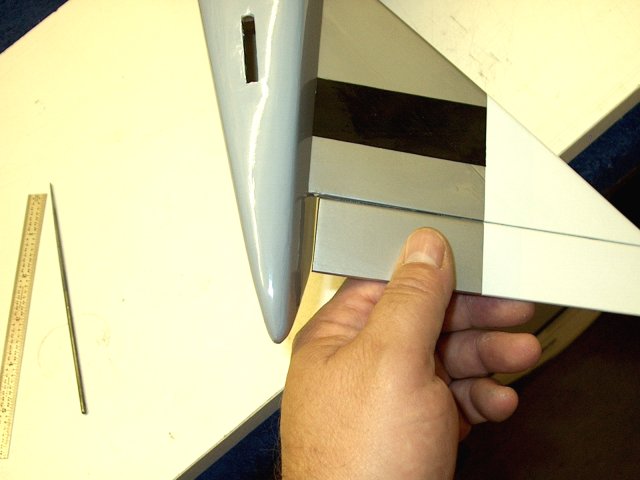
Position of tape as shown. Important: For
the next steps, make sure your model is flush against the
bottom of the table. You will need to hang the nose of the
fuselage off the surface as it is lower than the fuselage
bottom and can prevent the fuselage from sitting flush on the
table | |
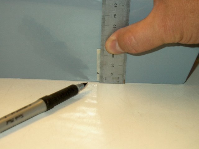
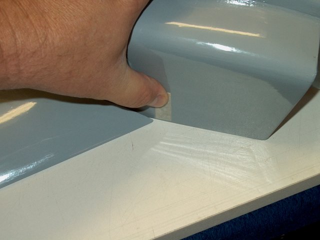
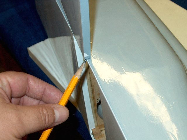
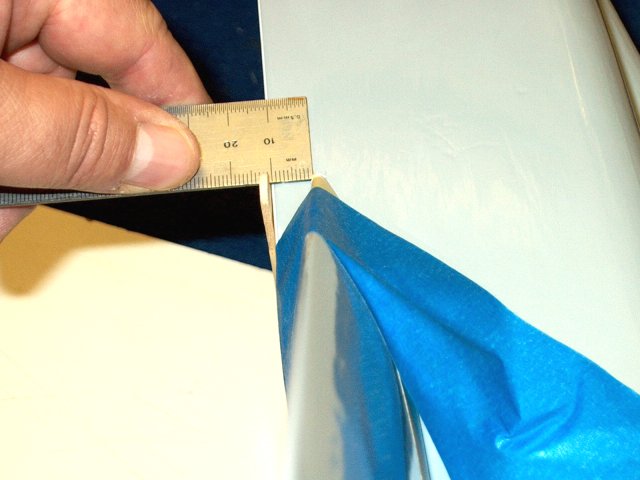
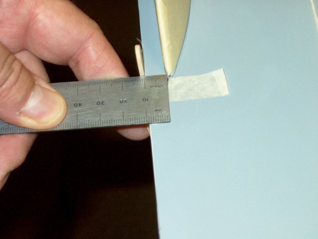
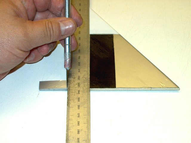
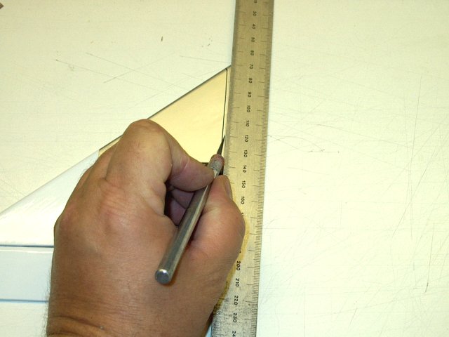
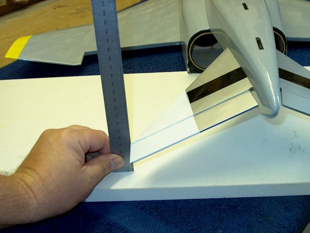
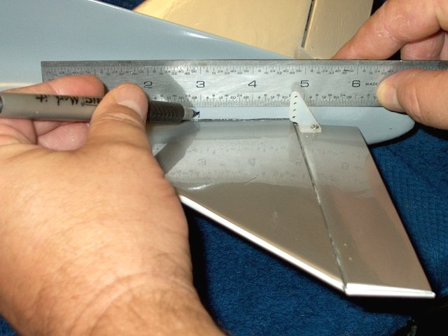
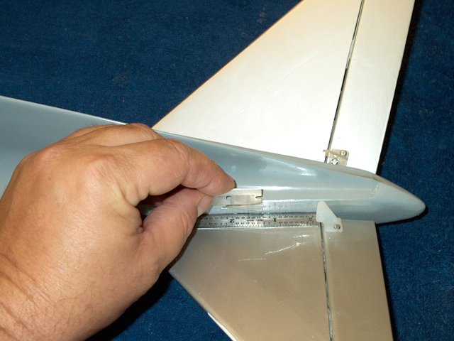
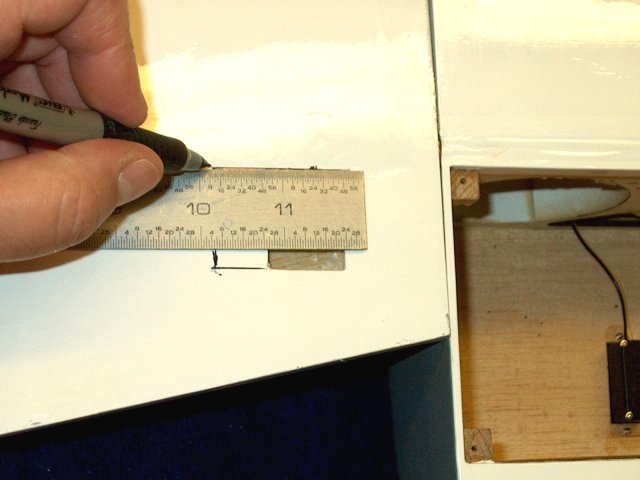
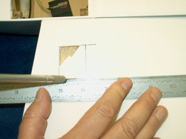
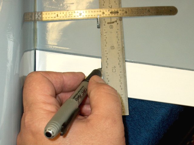
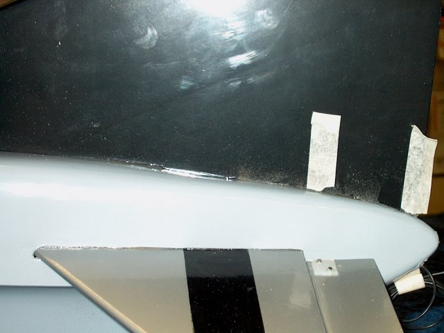
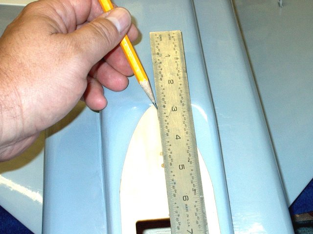
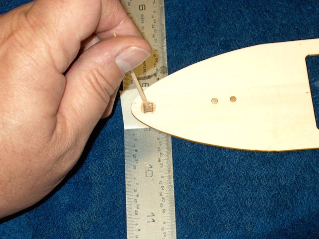
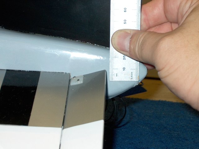
With the fuselage flush against a hard
surface, use a ruler and make a mark on the tape 10mm from the
bottom of the table as shown | |
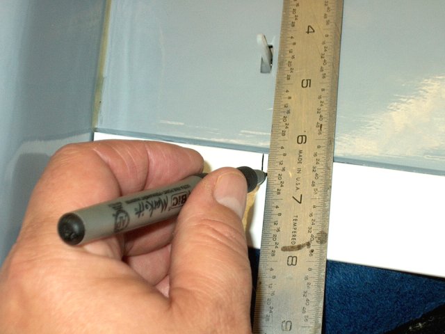
Mark the other tape strip in the same
manner, 10mm up from the surface | |
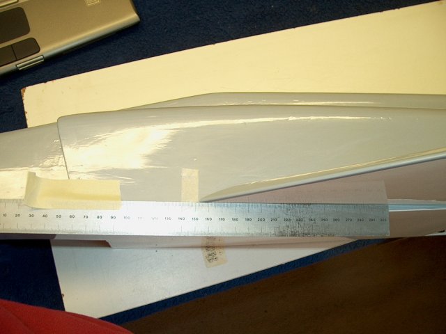
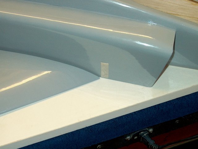
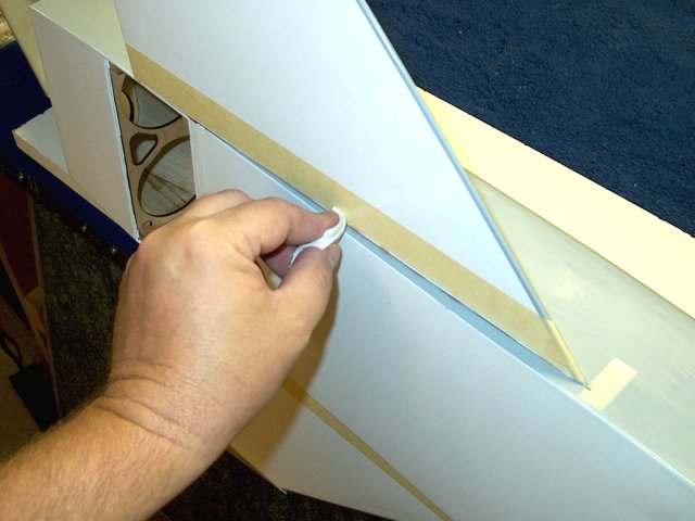
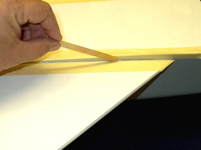
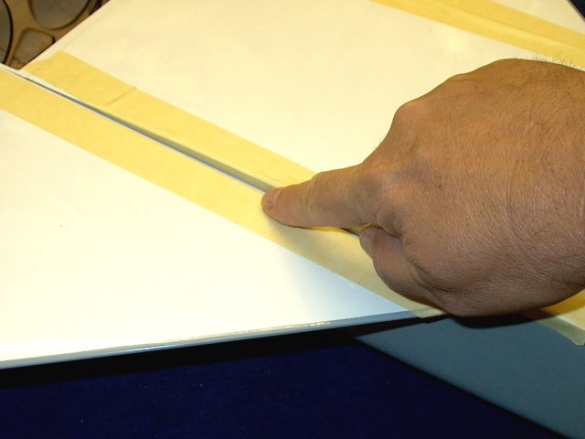
A ruler is used to help align the wing to
the mark. The bottom tip of the wing is at the 10mm position
as shown | |
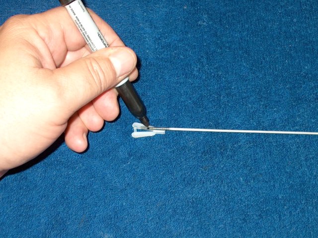
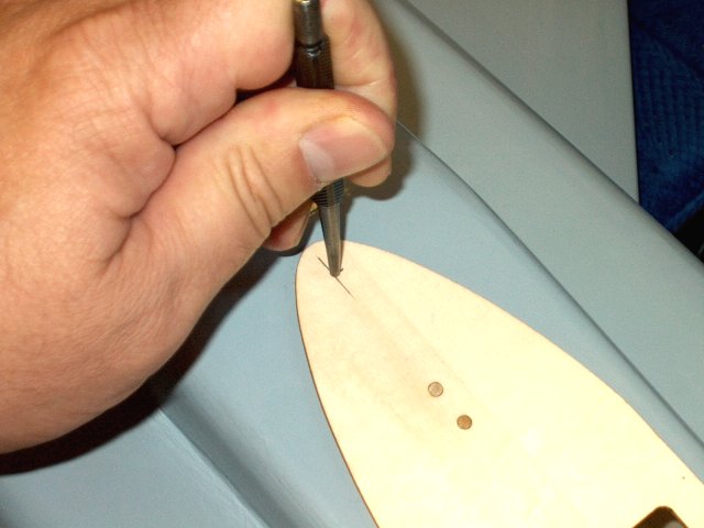
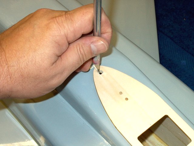
When in position, press the wing down to
make a dimple into the fuselage side, which marks the wood
dowel position on the side of the fuselage
| |
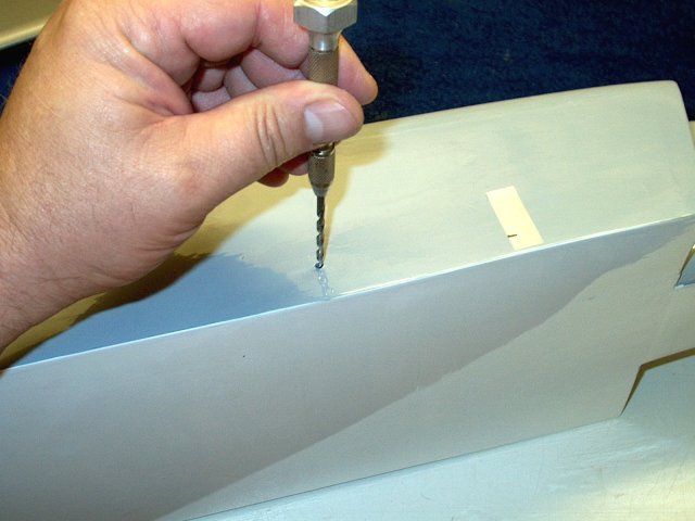
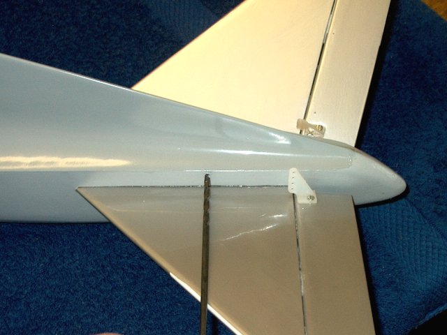
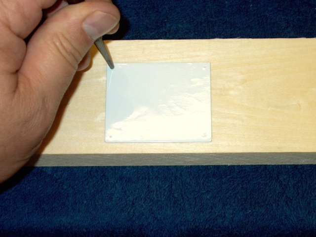
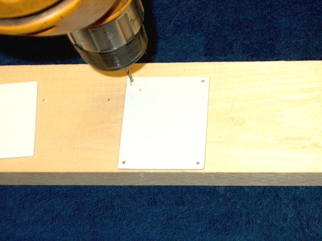
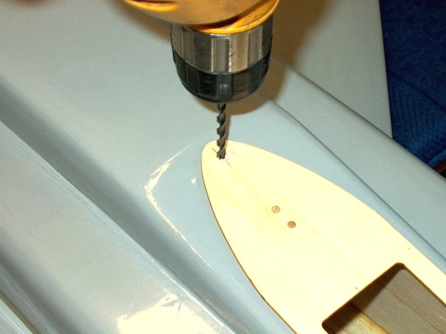
Remove the wing and open the dowel mark
with a 1/8" drill | |
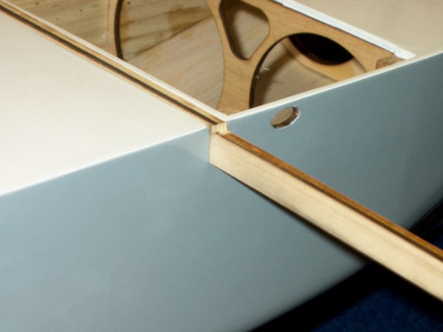
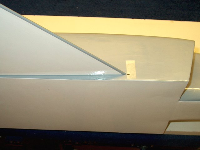
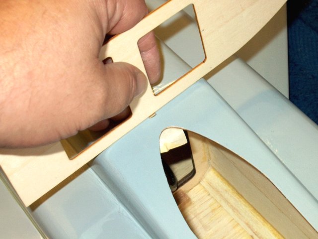
Install the wing and check for a good fit
and correct wing alignment at the 10mm mark
| |
Some overhang of the wing trailing edge
past the bottom of the fuselage is normal
| |
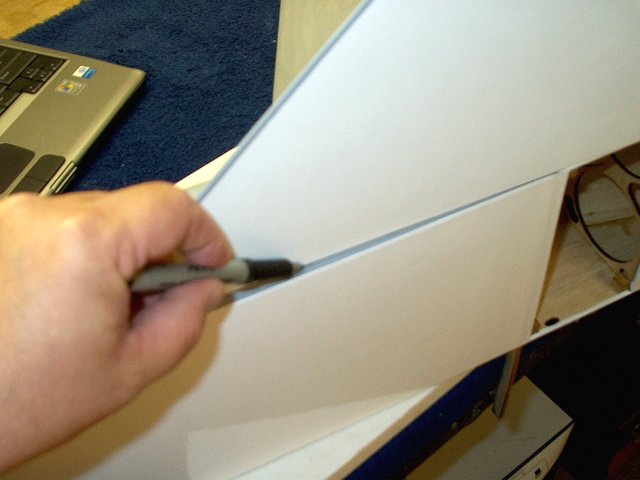
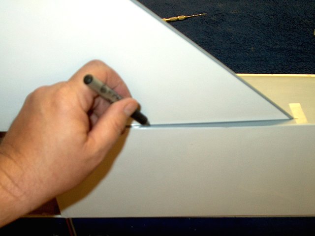
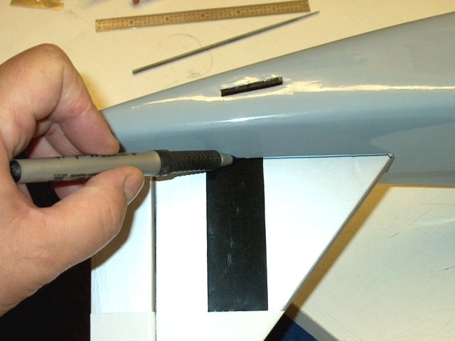
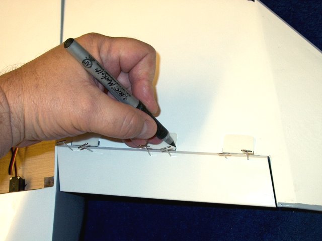
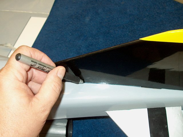
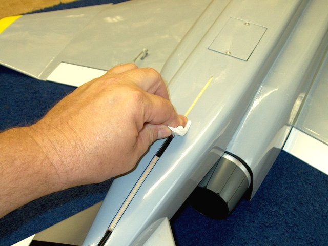
Use a marker and trace the wing root
pattern on to the fuselage | |
Remove the wing to reveal the wing root
pattern | |
Install the other wing and align it, then
press down to mark the dowel position
| |
Remove the wing and drill the hole for the
wing dowel pin | |
Install the wing and check the alignment
| |
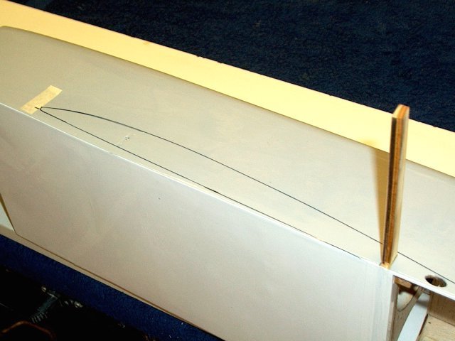
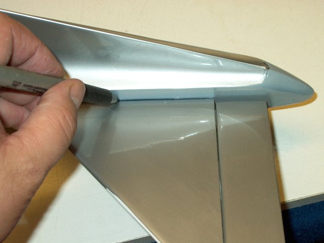
Trace the second wing root pattern on the
fuselage | |
Removing the wing shows the root pattern
that was traced | |
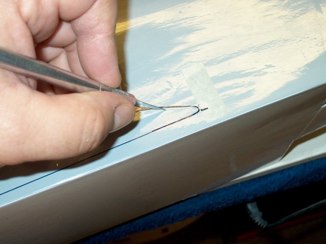
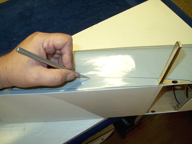
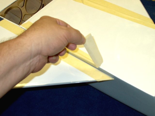
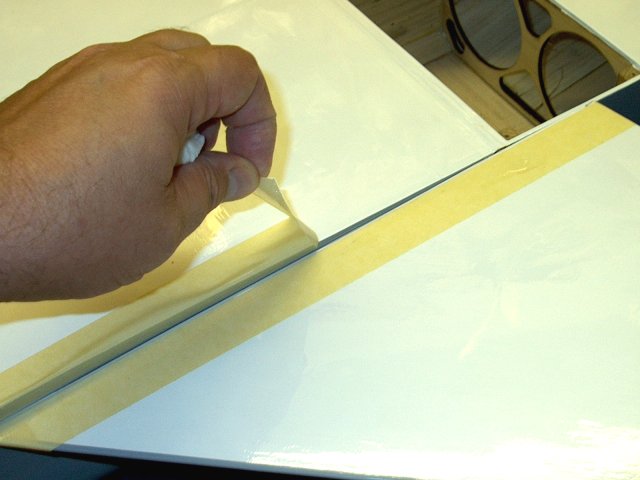
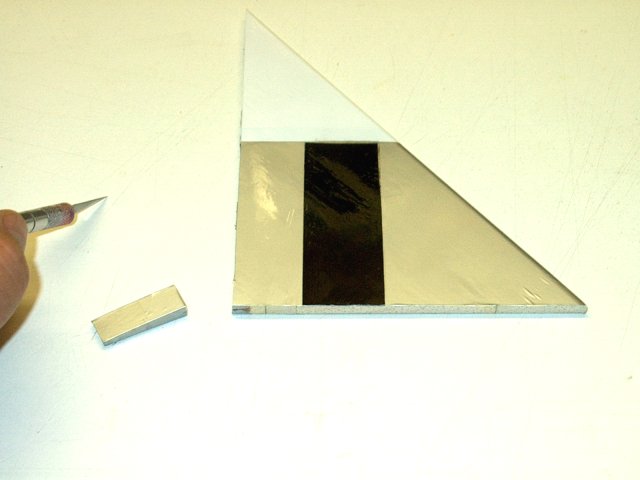
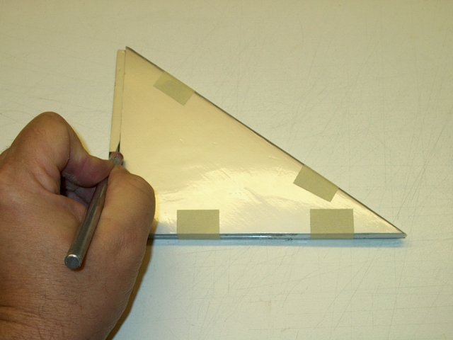
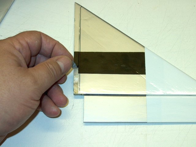
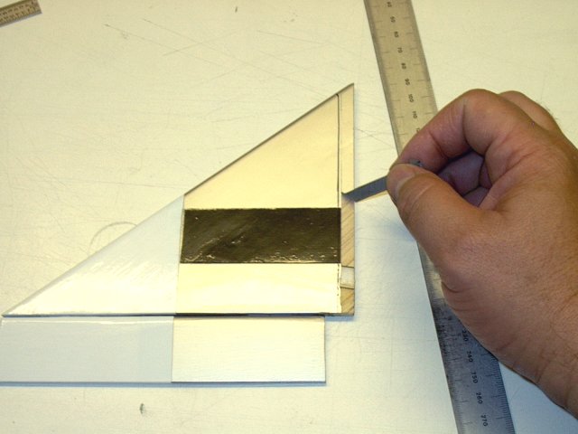
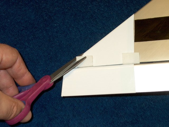
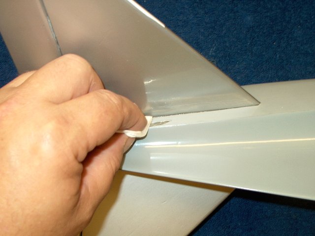
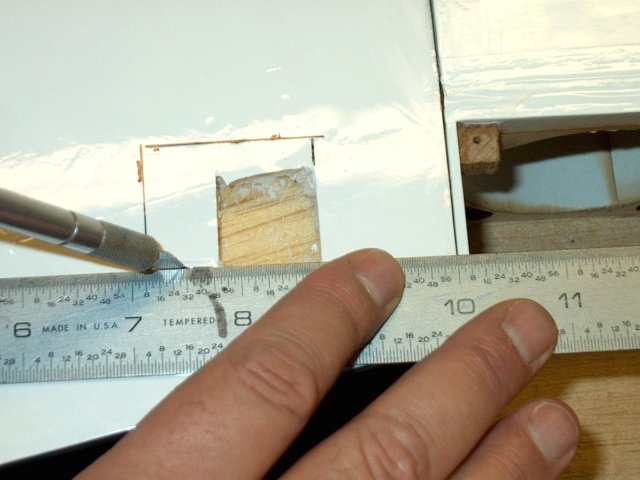
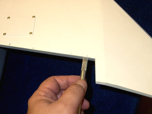
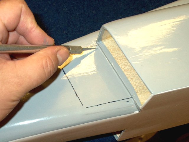
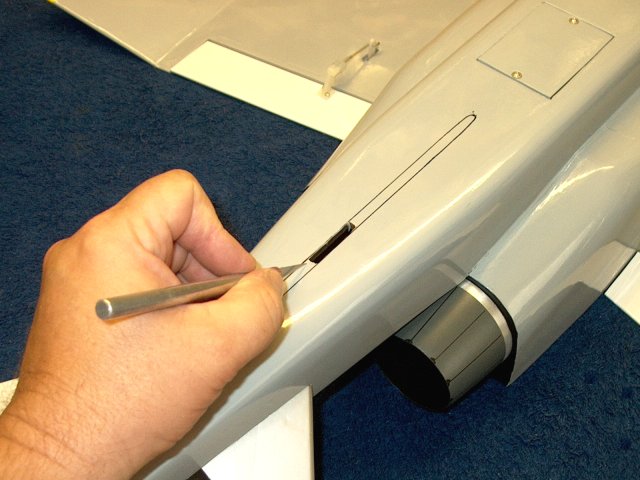
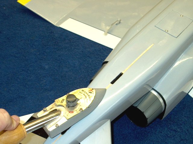
Cut the covering about 3/32" inside the
drawn pattern for the wing | |
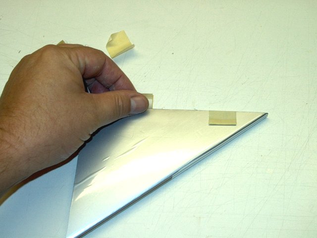
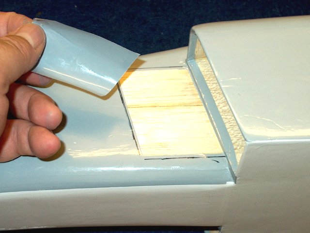
Remove the material as shown
| |
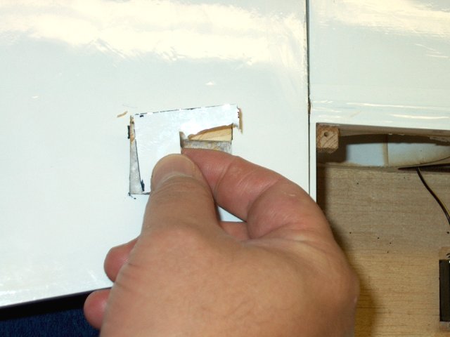
Wing root covering removed
| |
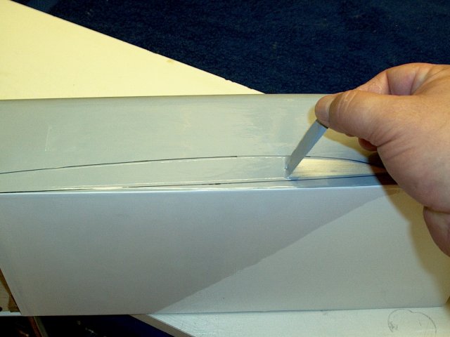
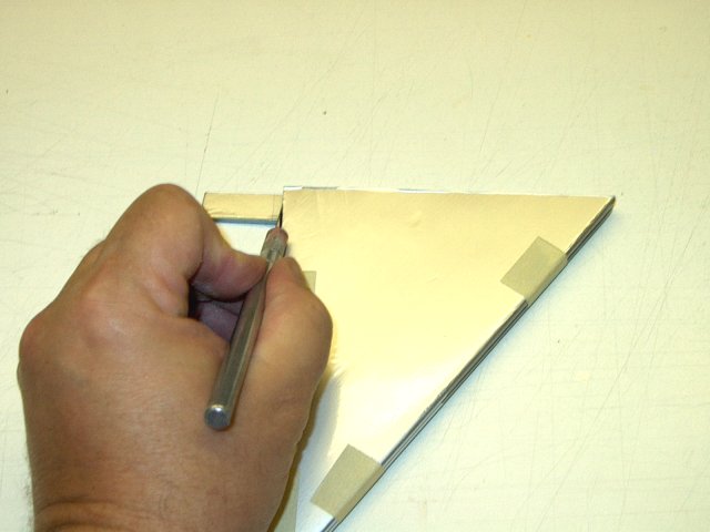
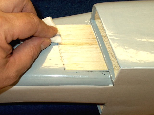
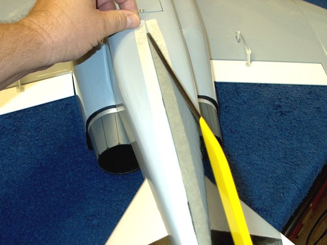
Cut the second wing root area, being
careful not to cut into the wood below
| |
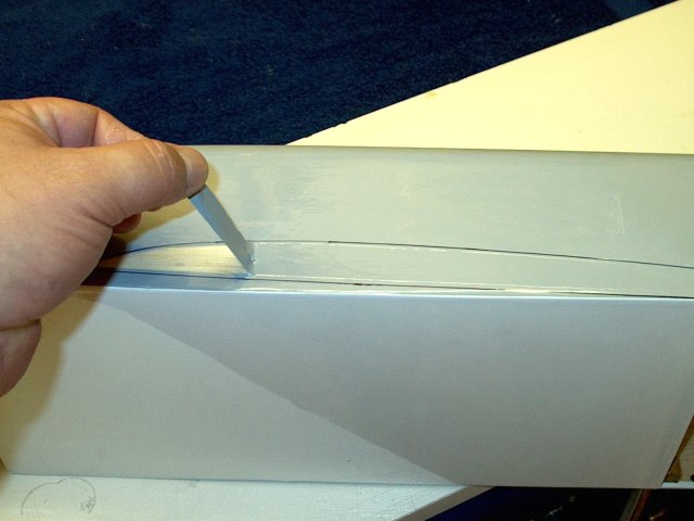
Removed the excess covering
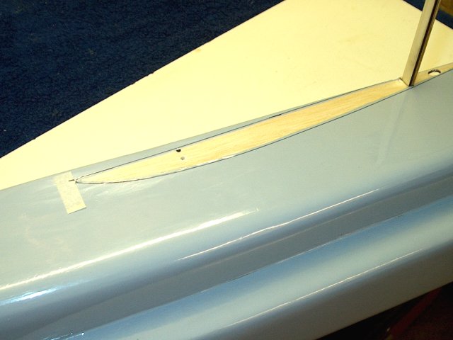
| |
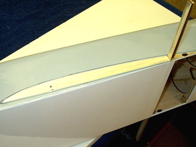
Second wing root is exposed for gluing
| |
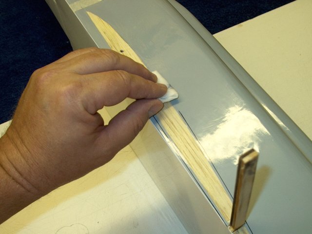
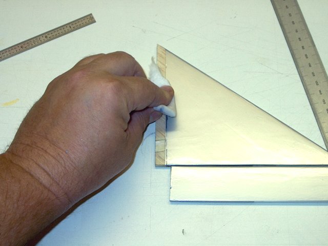
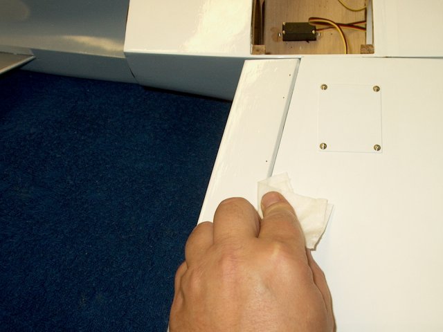
Use a small paper towel and denatured
alcohol to remove the marker lines from the fuselage and wings
| |
Use an iron to seal the cut area to the
fuselage on both sides | |
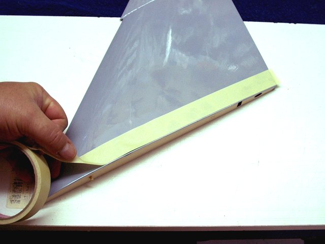
Masking tape is applied 1/16" away from
the inside root of both wings | |
Masking is applied on both sides, top and
bottom. This will aid in cleanup later on
| |
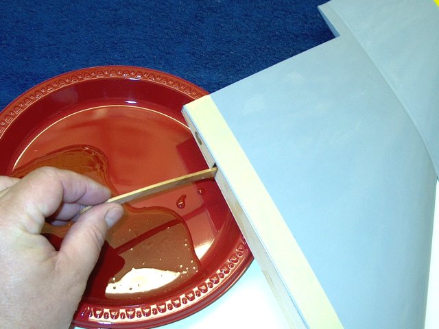
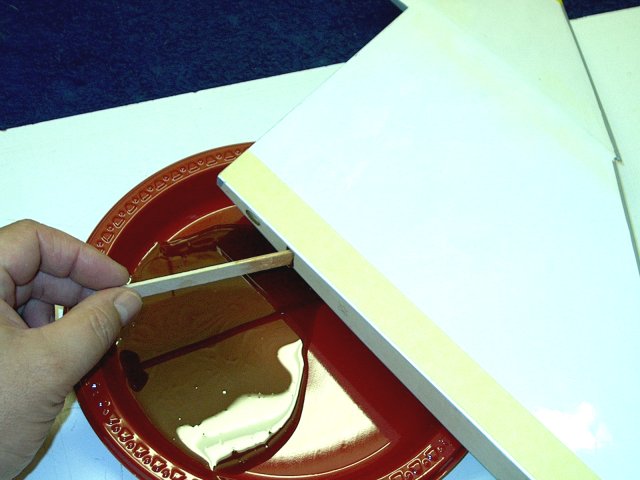
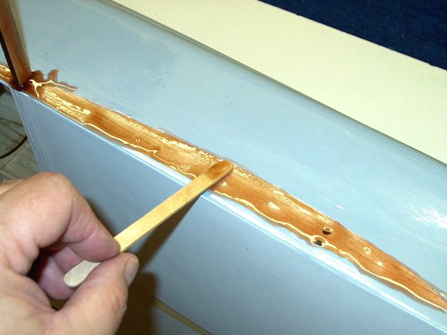
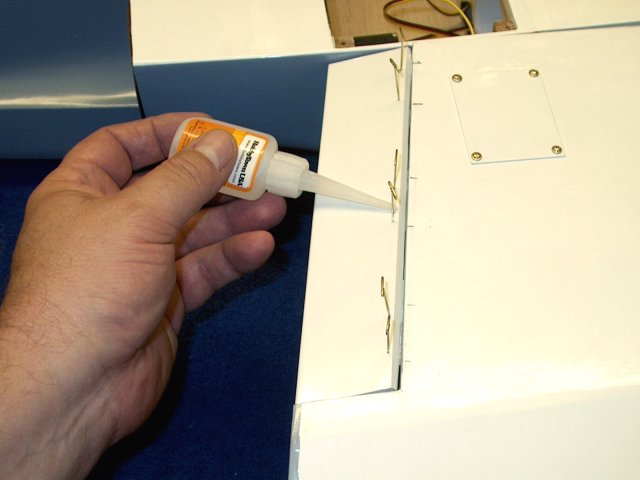
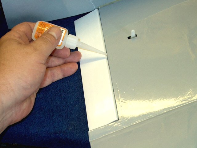
Mix up some 15-30 min epoxy and apply
epoxy liberally to the wing slot for the main spar
| |
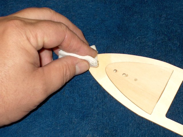
Apply epoxy to the entire wing root
| |
Epoxy is then applied to the main spar on
all sides | |
A thin coat of epoxy is applied to the
fuselage wing root area | |
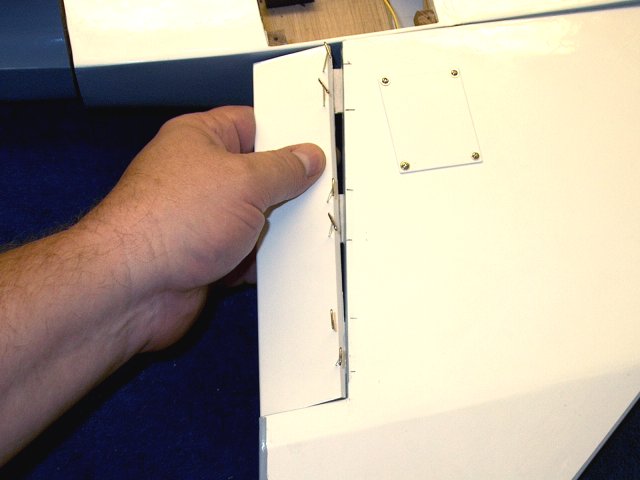
Install the wing on the fuselage
| |
Clean up any excess epoxy with a paper
towel and denatured alcohol | |
Wing glued in place and waiting for epoxy
to set | |
A measurement is taken before the epoxy
sets to insure the leading edge of the wing is 10mm from the
bottom of the fuselage. | |
Mix up some more 15-30 min epoxy and apply
epoxy liberally to the wing slot for the second wing's main
spar | |
Apply epoxy to the root of the second
wing | |
Wing root with epoxy ready to
assemble | |
Next, apply a thick ammount of epoxy to
the main spar | |
Epoxy is also applied to the fuselage wing
root area | |
Install the second wing flush on the
fuselage | |
Clean any extra resin with an alcohol
soaked towel | |
Check alignment for the second wing with a
leading edge of 10mm from the bottom of the fuselage
| |
Second wing installation completed. Allow
some time for the epoxy to set | |
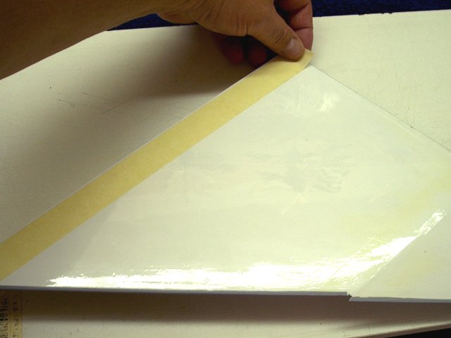
Tape is applied to both surfaces 1/16"
from the joint. This will make cleanup easier later
| |
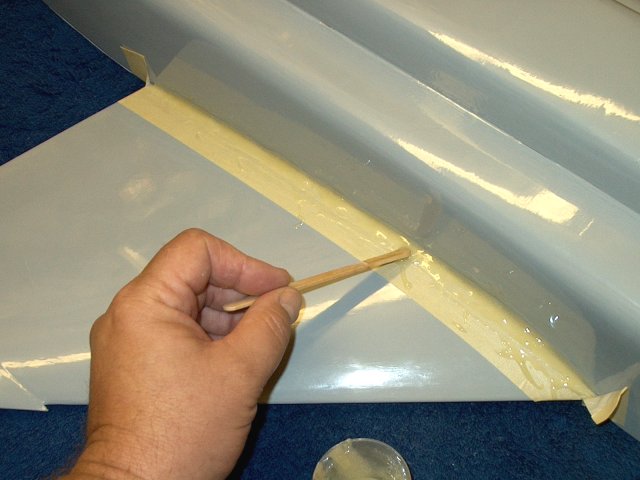
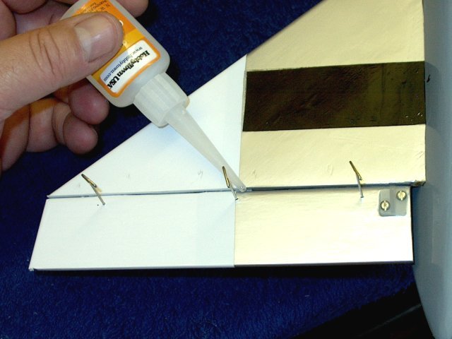
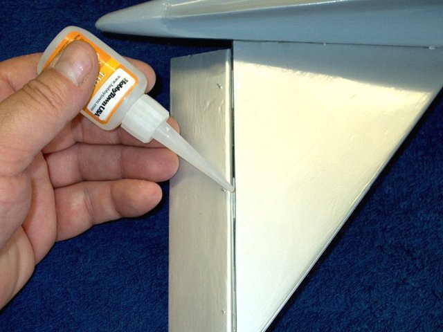
Epoxy is applied at the joint
| |
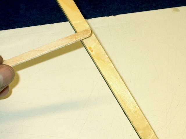
A fillet is made at the joint, removing
the excess epoxy | |
The tape is removed and and additional
cleanup is done with alcohol before the epoxy sets
| |
Epoxy is applied to the other bottom
joint | |
Once again, a fillet is made at the
joint | |
Tape is removed before epoxy sets
| |
The top is done similar to the bottom.
Apply epoxy and make a small fillet at the joint
| |
Clean up any excess with alcohol
| |
Fillet shown completed and dried
| |
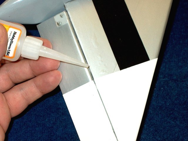
The other wing is done as shown with epoxy
being applied at the joint. A small round stick makes a great
fillet tool and the excess epoxy cleanly spills over on the
tape | |
The tape is removed before the glue
sets | |
The fillet is shown completed
| |
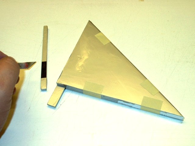
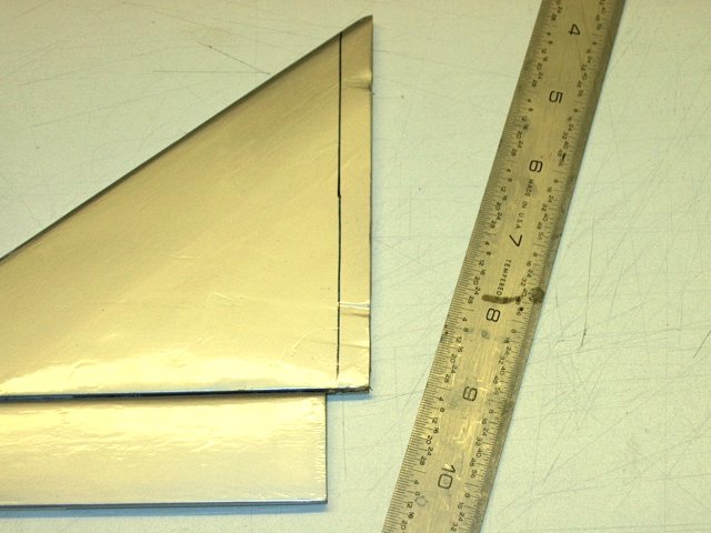
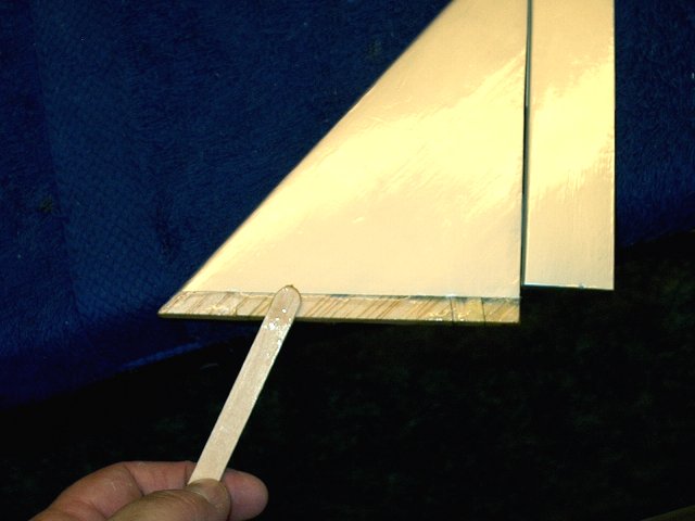
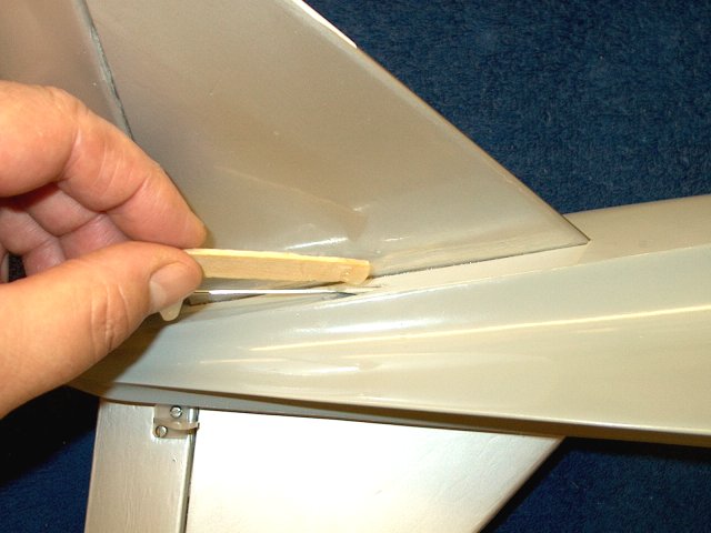
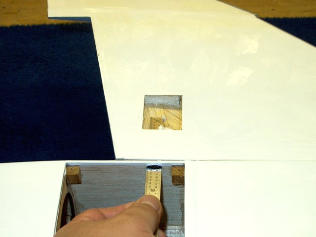
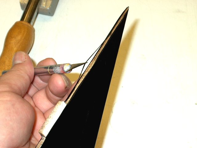
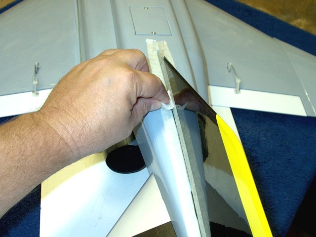
The root end of a horizontal stab is
measured at 9/32" | |
Trim off the excess at the measured
line | |
Stab shown trimmed
| |
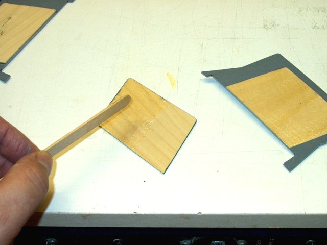
Lightly sand the root so it is
square | |
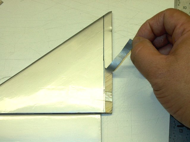
The trailing piece is cut with a
knife | |
Trailing piece shown removed
| |
The two stabs are taped together, keeping
the rear and leading edge even | |
The second stab is trimmed using the other
stab for reference | |
Second stab shown trimmed
| |
The trailing tab is removed on the second
stab as shown | |
Remove the tape and lightly sand the root
of the second stab | |
Seal the trailing edge of each stab with
an iron | |
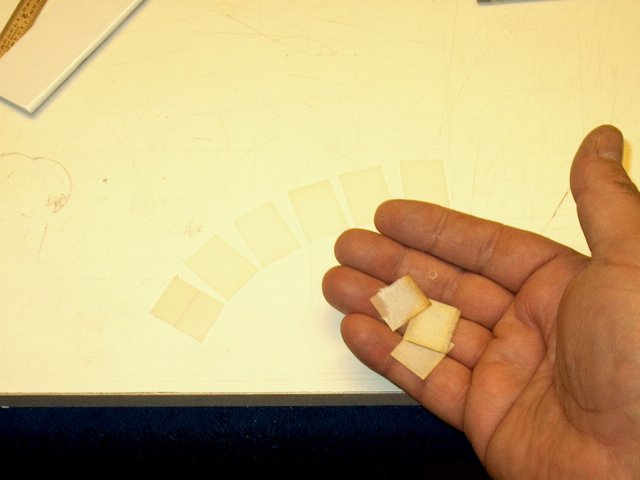
The hinges supplied in the kit were of
poor quality with fabric missing. New Easy Hinges were
substituted | |
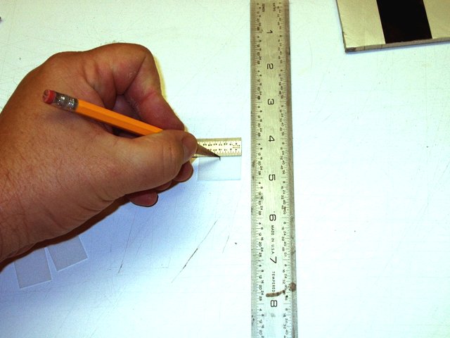
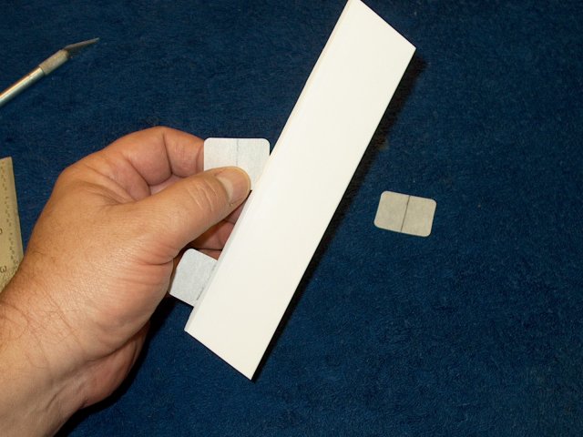
The center point is marked on each
hinge | |
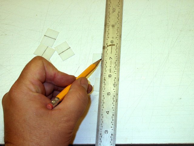
Draw a line down the center of each
hinge | |
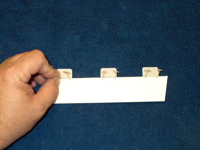
Install the hinges to center, opening up
the slots with a knife if needed, then install the
elevators | |
Use a round file to angle the forward slot
on the fuselage | |
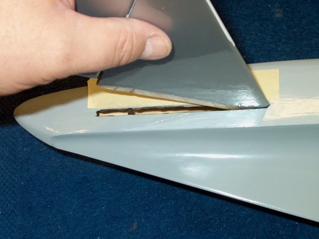
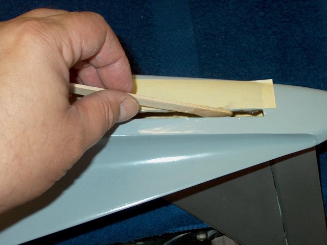
Fit the stab in the fuselage, making sure
the forward slot is long enough for the rear to fit
| |
The rear should pivot and just fit in the
slot | |
Down throw will be 10mm, so make sure the
elevator doesn't bind too early when flexed downward
| |
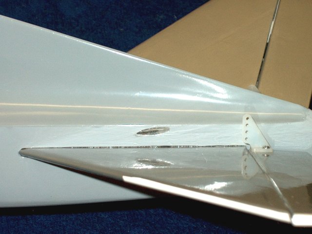
Mark the top of the fin for the fuselage
location | |
Mark the bottom of the fin for the
fuselage location | |

The stab is removed showing the marks that
were made and the material is cut about 1/16" inside of the
line | |
Remove the material from the root
| |
Clean up the line drawn with denatured
alcohol | |
Bottom of the fin showing mark that was
made | |
Use a ruler to cut the covering 1/16"
inside of the line | |
Remove the excess covering
| |
Clean up the drawn line with
alcohol | |
Use an iron to seal both sides where the
material was cut | |
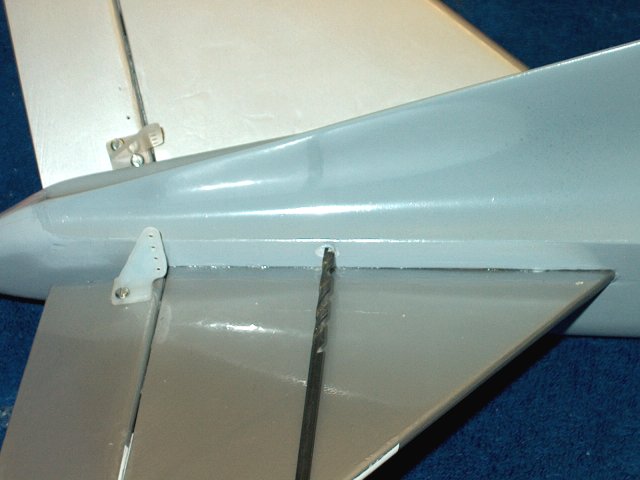
Install the stab to check for fit once
more | |
Use the hinges and install an elevator on
the second stab | |
File the front of the slot at an angle and
continue until the stab fits well | |
Draw a line on the top of the stab with a
marker | |
Another line is drawn on the bottom side
of the stab | |
The stab is removed and a ruler is used to
cut about 1/16" inside the drawn line
| |
The ecesss covering is removed
| |
A ruler is used to cut the material on the
top of the stab | |
Excess material is shown removed
| |
Marker lines are cleaned up with
alcohol | |
Seal the covering with an iron, then
install the second stab in the fuselage and check for
fit | |
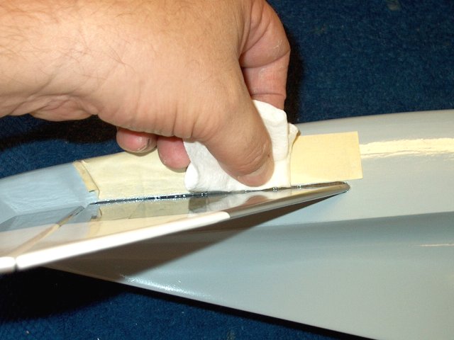
Tape is applied above the slot to keep the
covering clean when gluing the stab in place
| |
Apply a very thin coat of epoxy to each
side of the stab at set aside to let it soak
| |
Apply epoxy to the top and bottom of the
slot and to the two inside formers | |
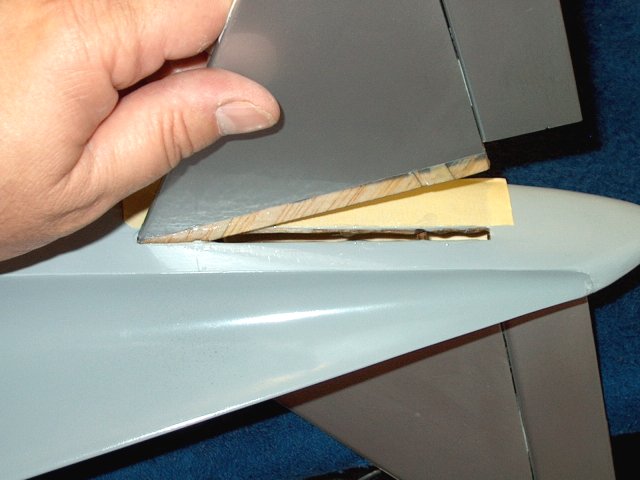
Install the stab into the slot. Note that
the stab fits in so it is at a downward angle, which is
normal | |
Clean up any excess epoxy from the joint,
both top and bottom | |
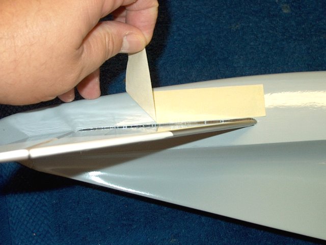
Remove the tape before the glue
sets | |
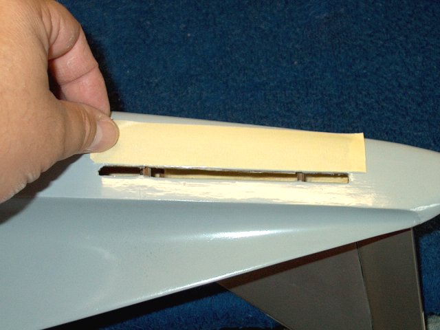
Prepare the second stab slot with
tape | |
Apply a thin coat of eopxy to both sides
of the stab | |
Apply an ample ammount of epoxy to the top
and bottom of the slot, as well as the two formers
| |
Install the second stab
| |
Remove excess epoxy with alcohol from the
joint on both sides | |
Remove the tape before the epoxy
sets | |
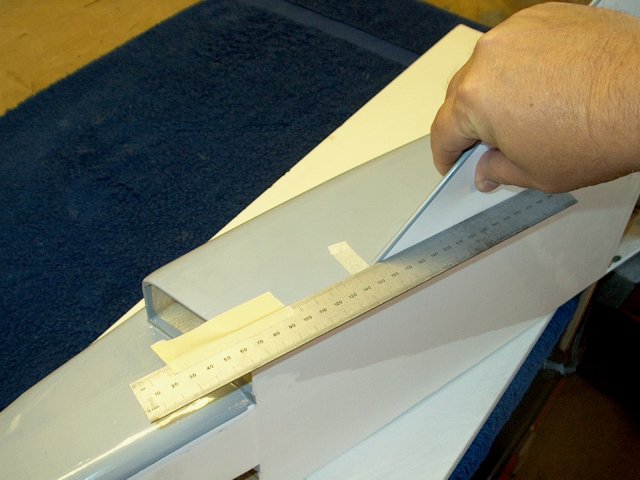
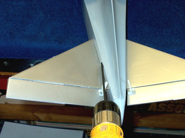
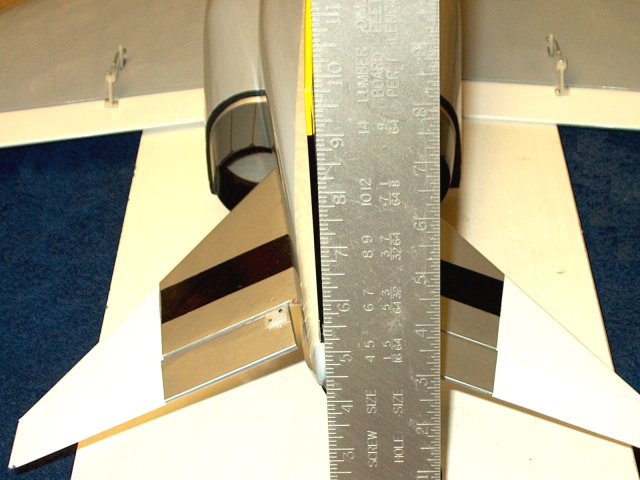
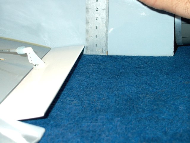
Quickly check alignment by placing the
bottom of the fuselage on a flat surface and measure one stab
as shown | |
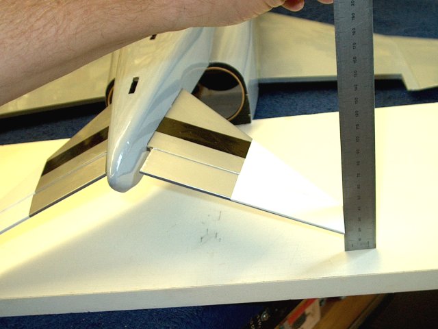
Check the other stab and make sure it is
the same distance from the board. prop up one side before the
epoxy sets if necessary so they measure evenly with
eachother | |
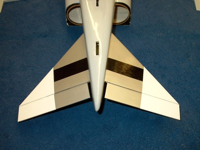
Stab installation completed as
shown | |
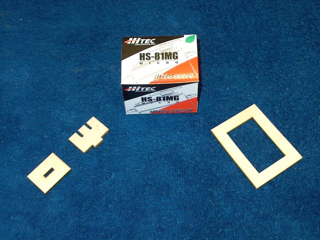
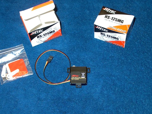
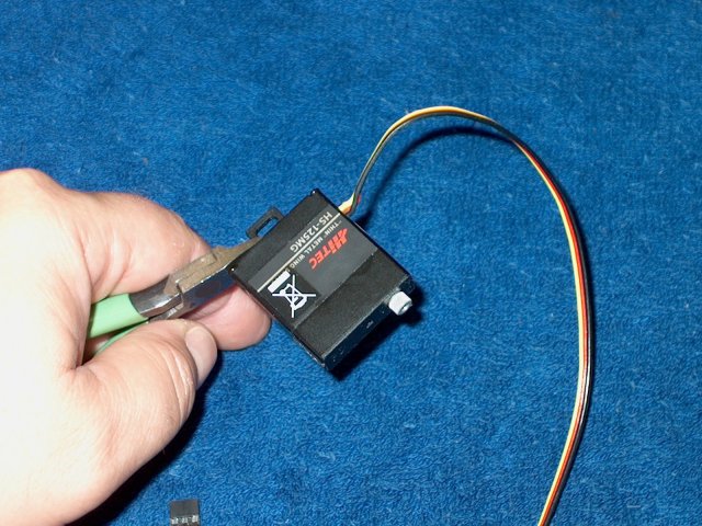
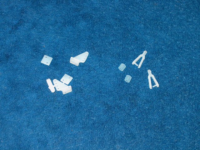
A good quality metal gear servo is used
for the elevator and is shown with the servo tray parts
supplied in the kit | |
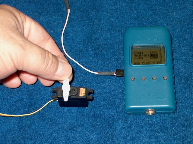
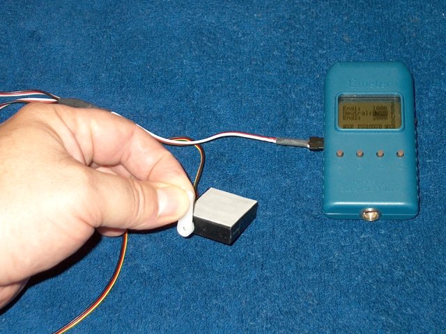
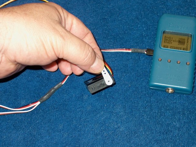
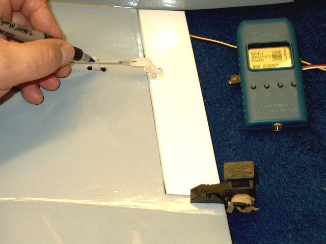
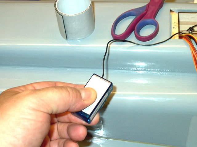
Center the servo with a receiver or servo
tester | |
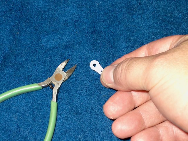
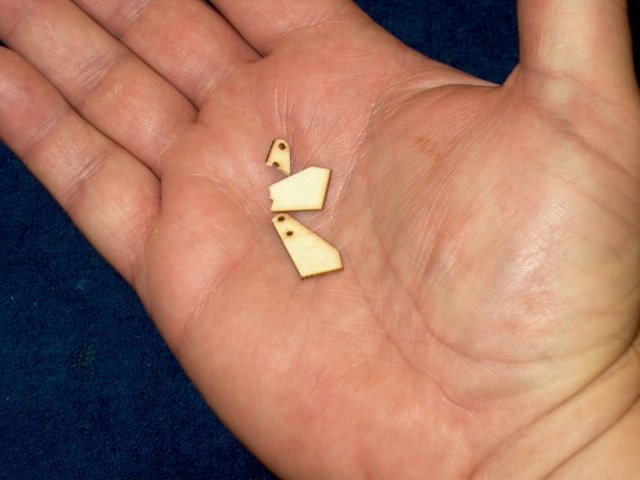
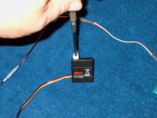
Trim one end of a servo horn as
shown | |
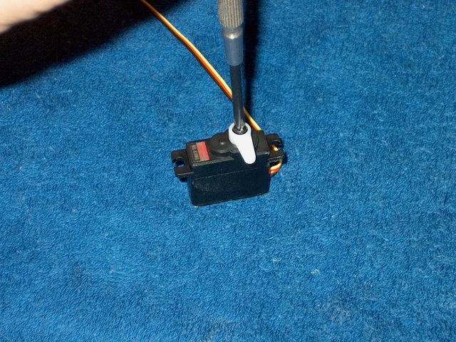
Install the horn on the servo, making sure
it is centered | |
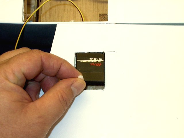
The selected servo is now slightly larger
than the opening in the supplied servo tray. You may have to
enlarge the opening to fit your make of servo
| |
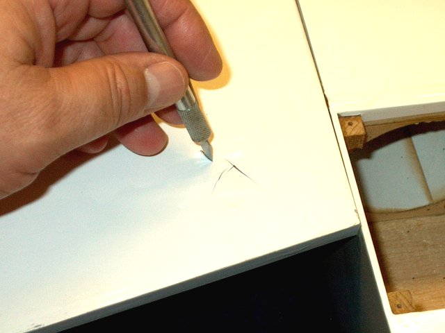
The tray is marked evenly on each side to
widen the opening just enough for the servo to pass
through | |
A tool is used to open up the hole. Files
and some light sanding are used to finish the work
| |
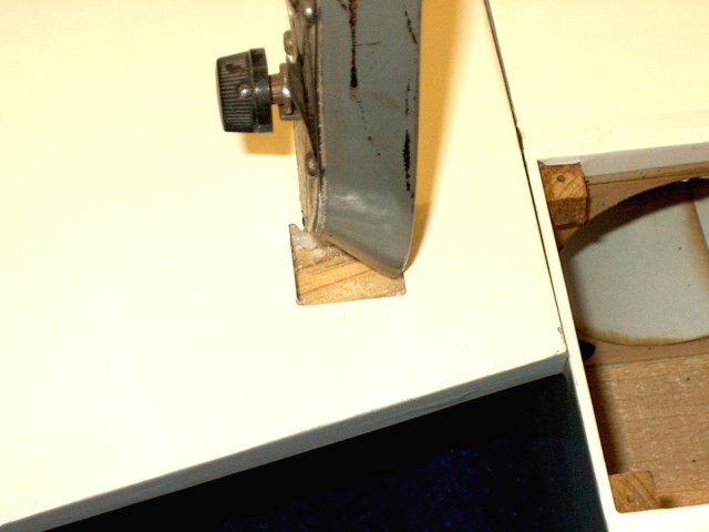
The servo should easily fit through the
opening as shown | |
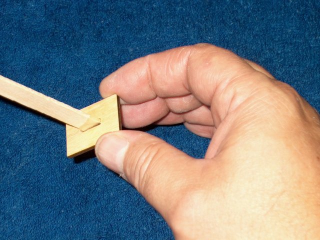
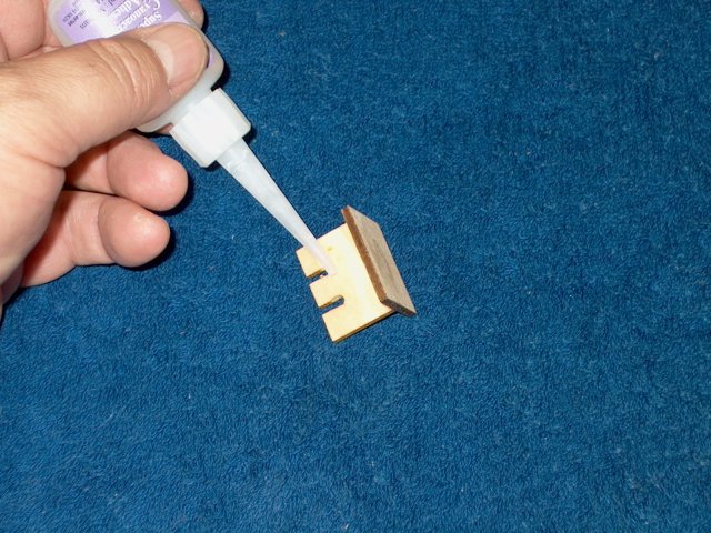
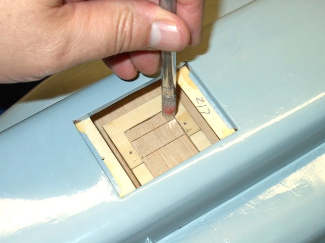
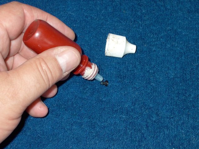
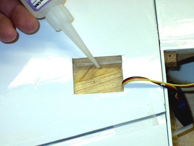
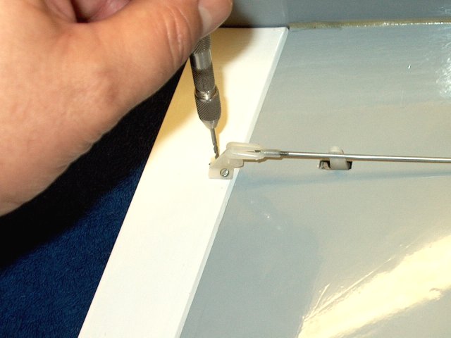
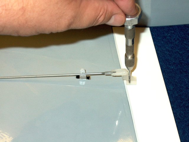
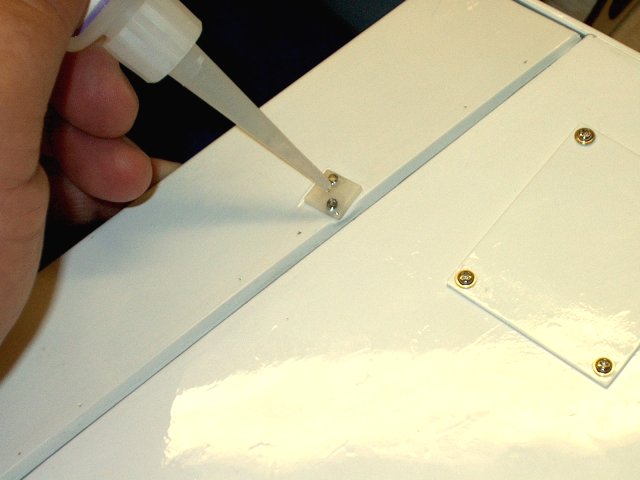
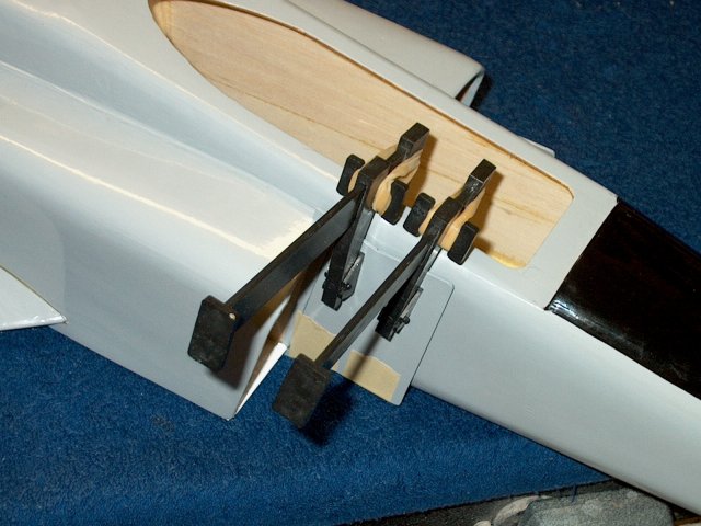
Epoxy is applied to the slot for the
pushrod bracket | |
Epoxy is applied to the vertical section
of the bracket | |
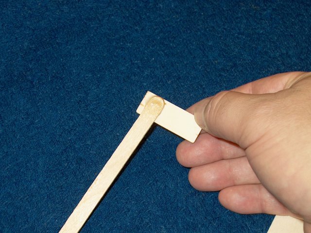
The to pieces are joined until they sit
flush with eachother | |
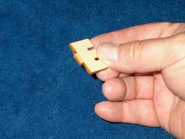
Some epoxy is added to create a fillet for
strength | |
Make sure the two pieces are perpendicular
to eachother, then set aside while the glue sets
| |
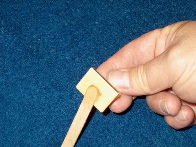
Sand the bottom of the assembly flush with
a sanding block | |
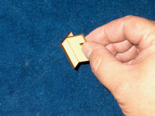
The bottom of the slots are slightly
enlarged for the pushrods | |
Test a pushrod sleeve to make sure it fits
well | |
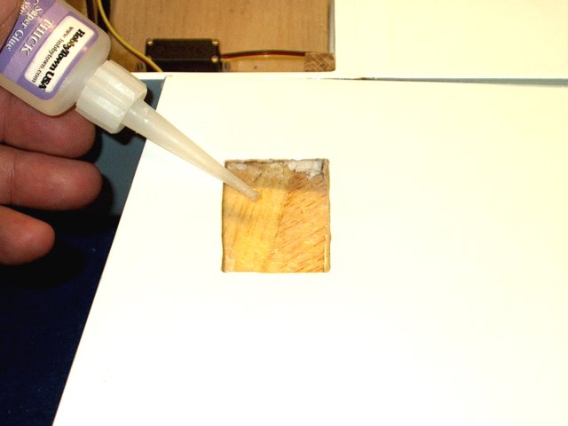
CA is used on the back side to stiffen the
plywood | |
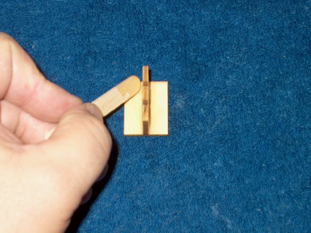
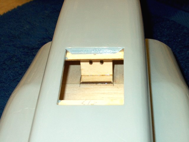
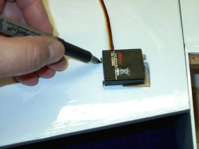
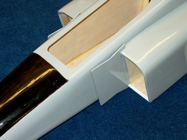
Position the bracket so it is centered in
the rear of the fuselage, just behind the seam in the balsa.
Next, draw an outside line on each side to mark the position
of the tray | |
Lines shown drawn once the bracket is
removed | |
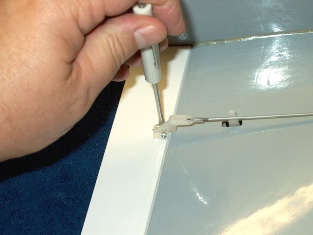
Apply epoxy to the bottom of the
bracket | |
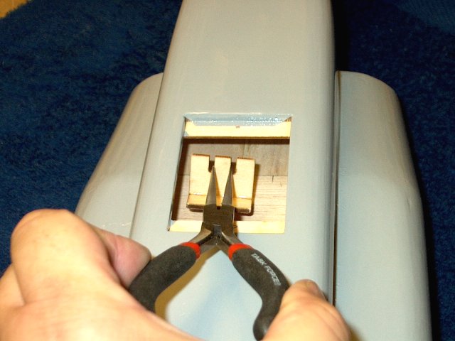
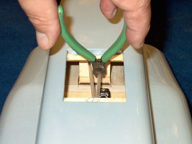
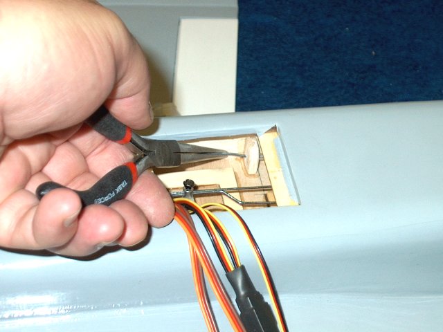
Use some pliers to position the bracket in
the fuselage. | |
Make sure the front is even with the seam
in the balsa floor as shown and that the sides are even with
the marks you made earlier | |
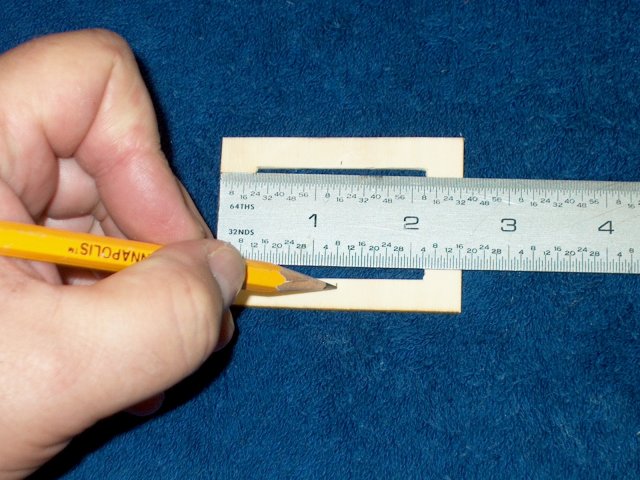
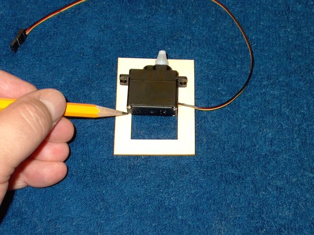
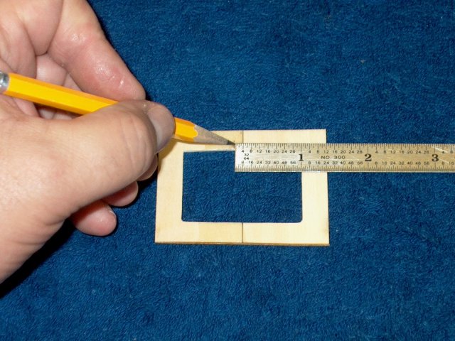
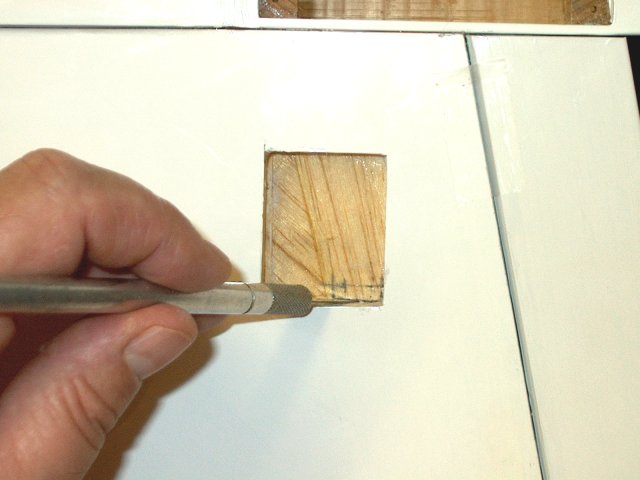
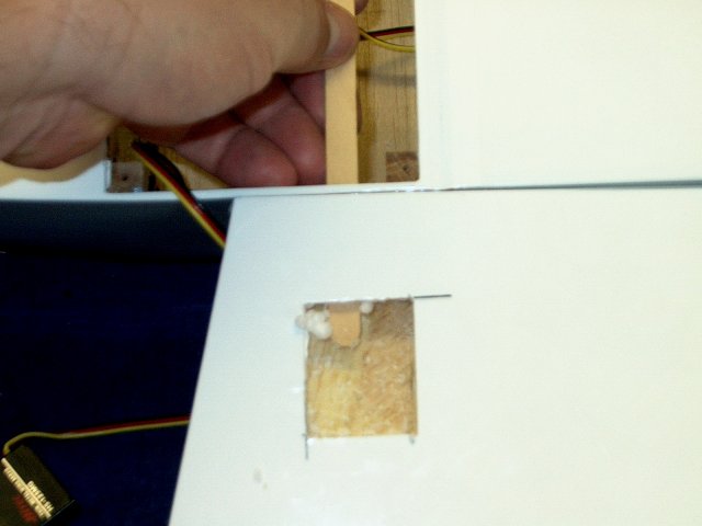
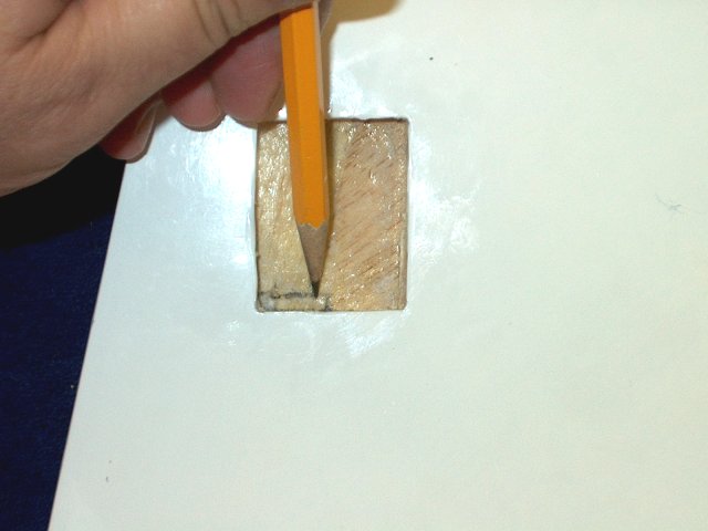
A mark is made for the center of the servo
tray | |
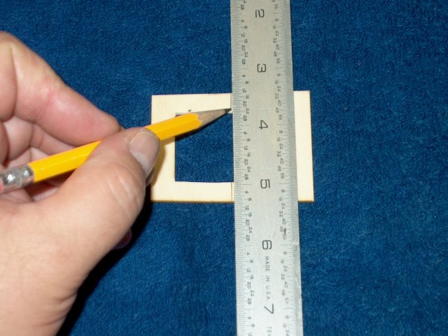
Drawn a line down the center of the tray
through the marks | |
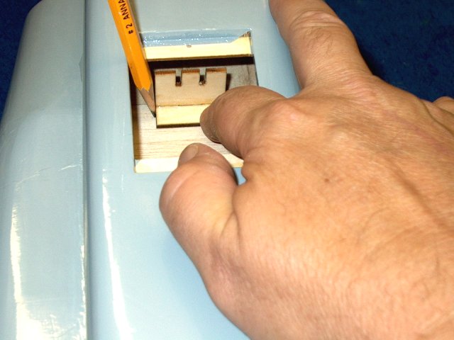
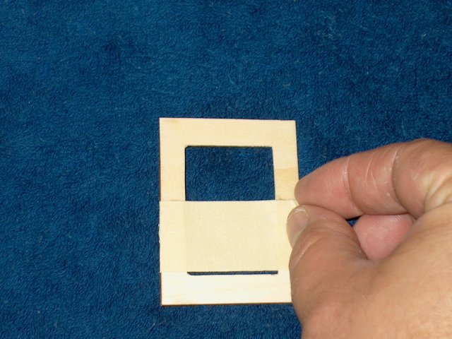
A 1/2" square piece of balsa is inserted
into the fuselage as a spacer | |
The bottom of the block is pushed flush
against the front edge of the pushrod bracket plate
| |
The servo tray is inserted into the
fuselage | |
The servo tray is pushed flush against the
balsa block and centered as shown | |
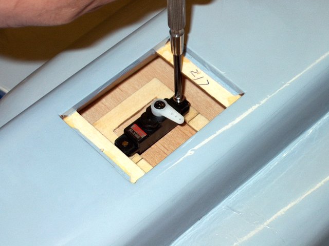
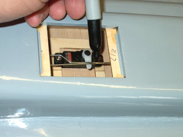
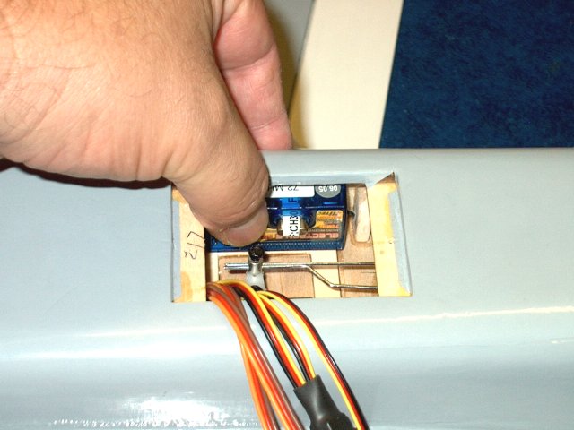
A screwdriver should be inserted to make
sure you have clearance to get to the servo screws that will
be installed | |
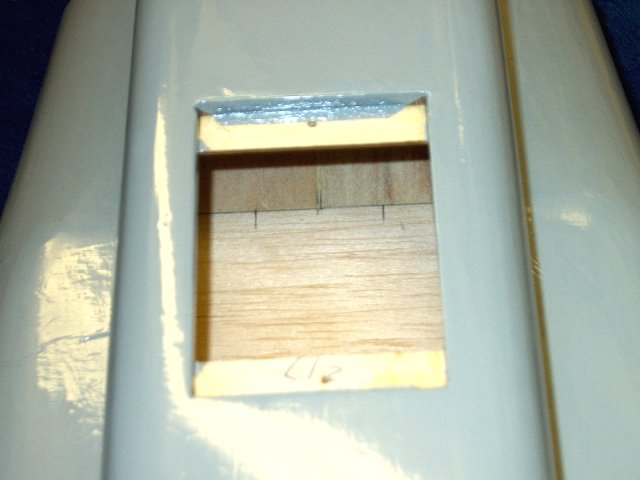
Draw an outline of the tray in the floor
of the fuselage | |
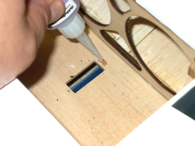
remove the tray and seal the top section
with CA where the servo screws will reside
| |
Allow the CA to dry
| |
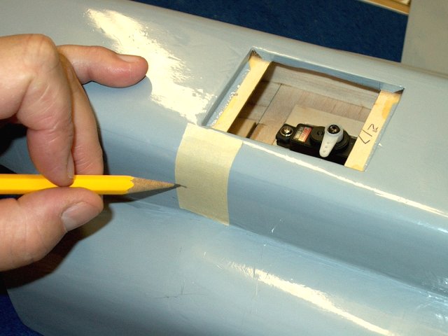
A mark is made top and bottom 1/8" away
from the centerline on the tray to space the servo so it is
offset from center. This is so the horn will be centered
instead of the servo | |
A couple pieces of tape are stacked across
the offset marks that were just made
| |
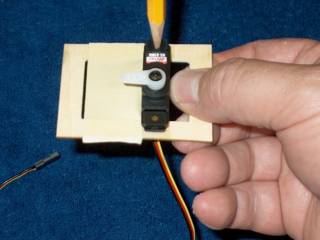
Add the grommets to the servo and install
it in the tray. While holding it in place, mark the holes for
the screws. NOTE: While a single servo is used for the
elevators, you can also use dual servos for the
elevators | |
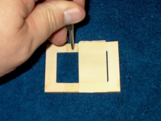
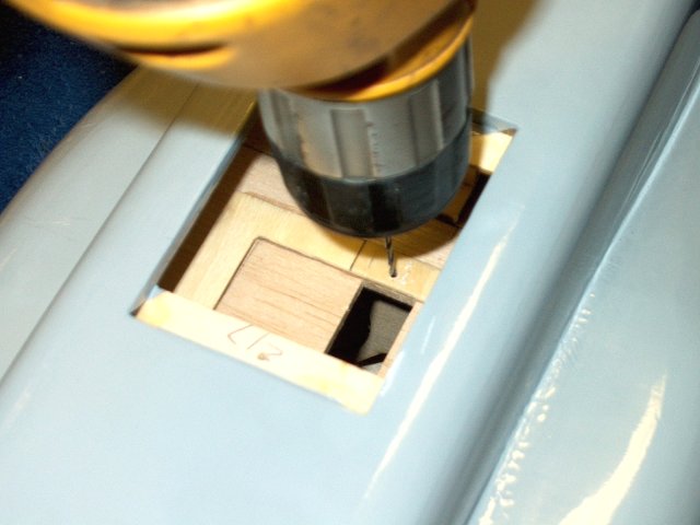
Use a punch to dimple the marks for the
servo screw holes | |
Use a 1/16" drill to make the holes for
the servo screws | |
A screw is used to initially "cut" threads
in the tray | |
Epoxy is applied to the bottom of the
tray | |
Use pliers to ease intallation of the tray
in the fuselage | |
Center the tray over the alignment marks
made on the floor, then press it down in place
| |
The tray had some warping, so a weighted
object is used to hold the tray down flsuh until the epoxy
cures | |
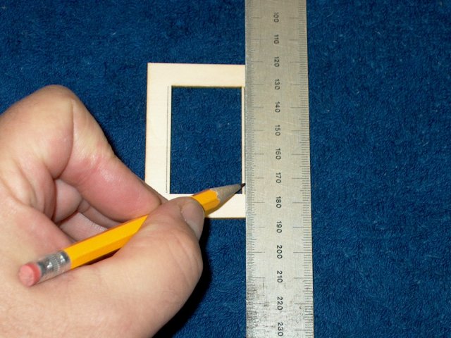
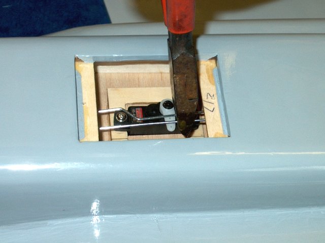
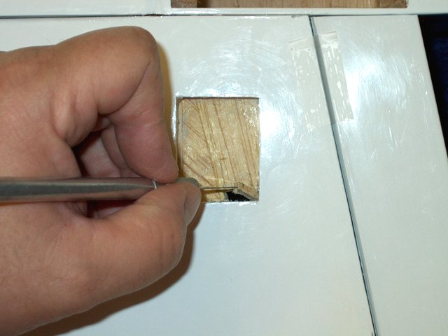
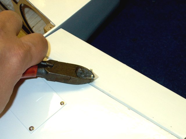
A ruler is placed across the two offset
marks where the tape was placed earlier and a knife is used to
cut the balsa. Make several passes and take your time
| |
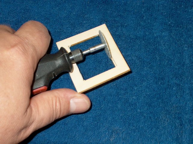
A ruler is used to cut the other side,
away from center and 1/2" wide or wide enough for the servo
you are using. note that a single edge razor was installed in
the first slot so the ruler could be pressed flush against it
while cutting the second slot | |
Be sure to cut completely through the
sheeting at the corners as shown, then cut across flush to the
tray and remove the balsa piece | |
A 1/16" drill is used to re-open the screw
holes, which most likely will have some epoxy in them
| |
The fuselage is turned over and CA is
applied to the bottom area around the screw holes to
strengthen them | |
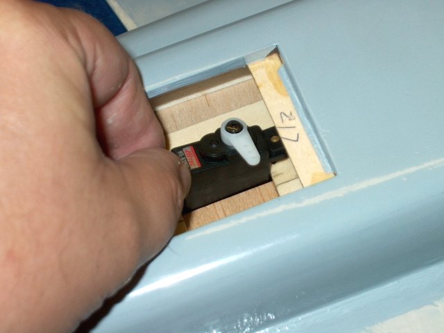
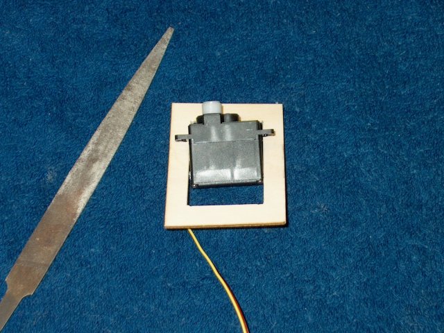
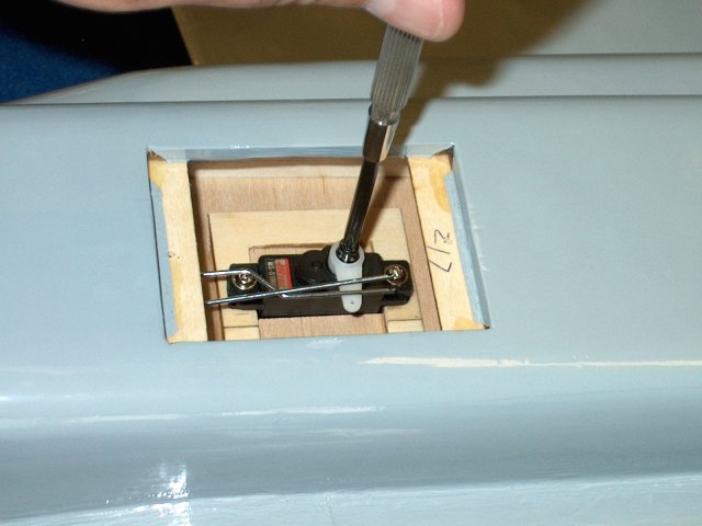
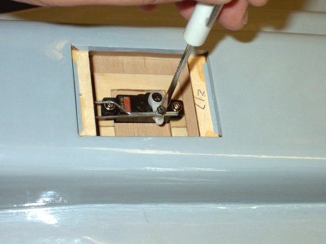
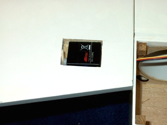
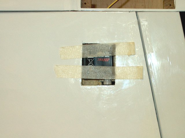
Install the servo in the fuselage
| |
Use the servo screws to permanently mount
the servo in place | |
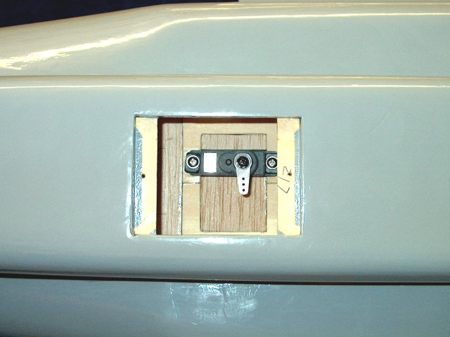
Servo installation shown completed
| |
Fit three hinges in each of the two
Elevators | |
The horns supplied in the kit were
discarded as they were too thin and flimsy
| |
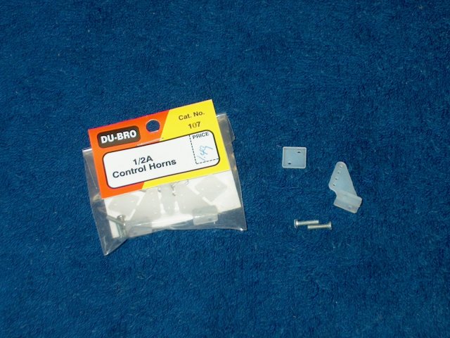
1/2A horns made for a good substitution
| |
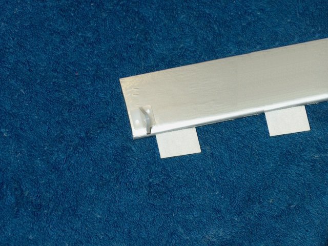
Horn shown in place ...take note of the
hole orientation and note that the horn will be mounted on the
bottom of the elevator | |
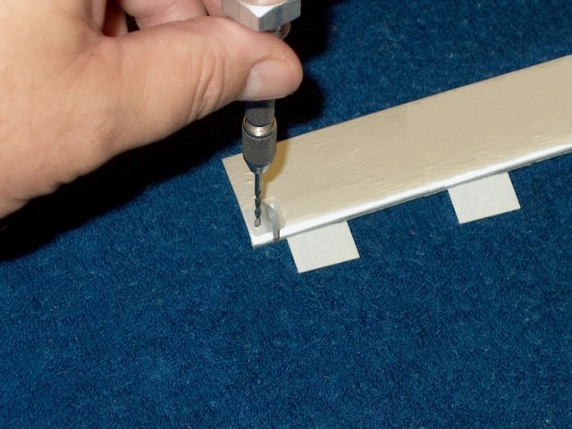
Use a 3/32" drill to open the holes in the
balsa. Stiffen the holes with thin CA
|
|
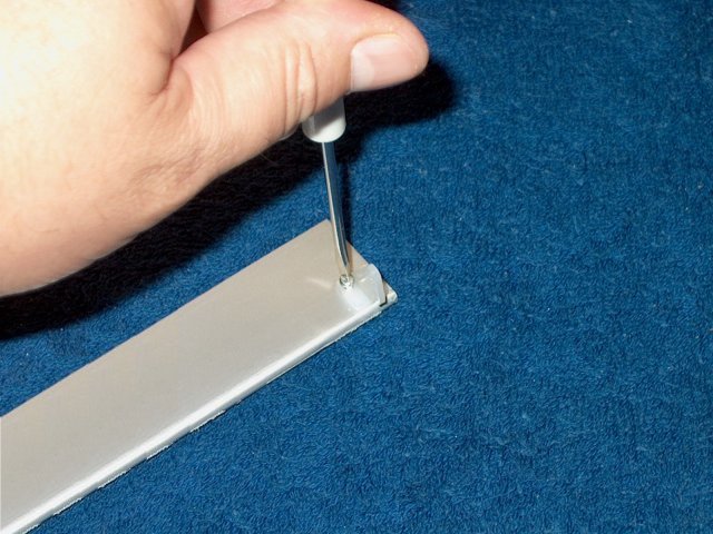
Install the horn on the bottom of each
elevator. Be careful to not over tighten the bolts
| |
Trim and grind the excess thread length
off from the bottom | |
Seal the ends of the bolts on each
elevator with a cap of thick CA so it won't snag or catch
anything while handling | |
The outside hinge requires some trimming
to fit | |
Install the elevator, opening the slots
for the hinges if necessary with a razor, then use thin CA to
glue them in place, Make sure the outer end is flush with the
stab | |
T pins are used to hold the hinges in
place so they do not shift or twist when installed. Apply thin
CA to both sides of the elevator hinges
| |
Install the second elevator the same as
the first | |
Elevator horns shown installed
| |
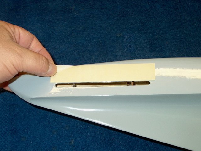
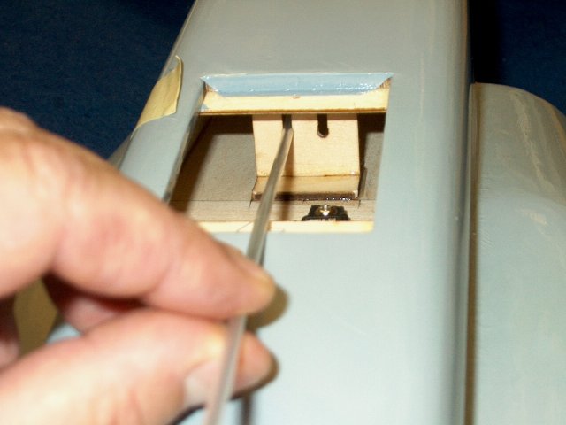
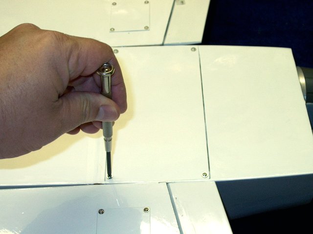
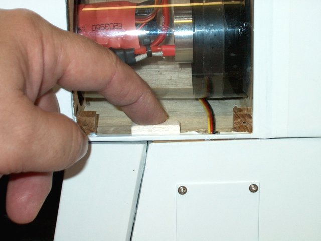
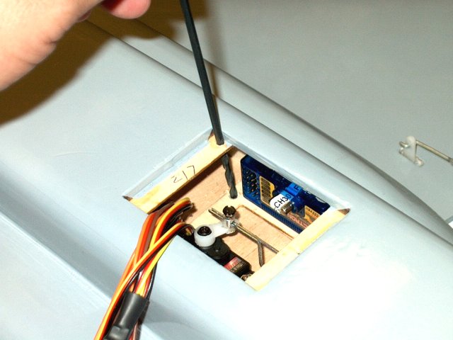
A piece of tape is applied to the side of
the fuselage and a mark made the same height of the bottom of
the pushrod bracket slot inside | |
Make a mark on the side of the fuselage 3"
from the front root of the stab | |
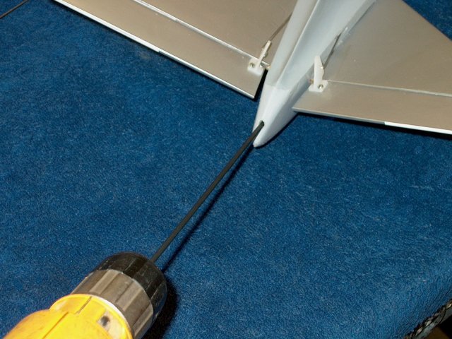
Drill a 1/8" hole at the mark and about
1/16" below the edge of the fuselage as shown
| |
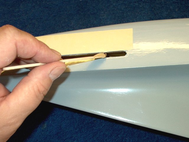
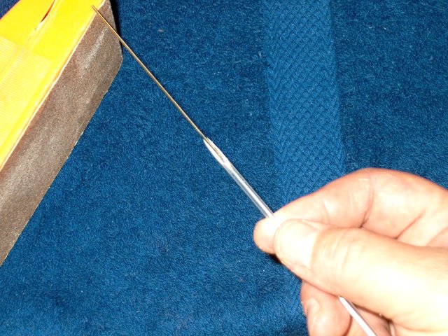
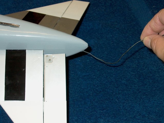
Use a long 1/8" drill bit like a file and
turn it foward, gradually opening the hole at an angle and
pointed slightly down toward the mark on the tape. Slowly
drill a hole internally that is angled down toward the pushrod
bracket | |

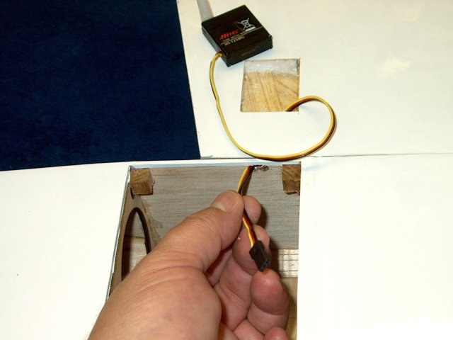
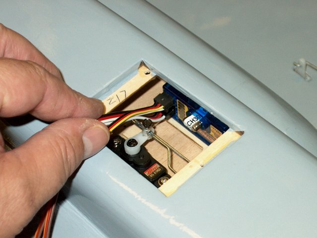
Install the pushrod, then slide the
pushrod sleeve over it and work it towards the bracket
inside | |
Remove the steel pushrod and check for
alignment of the sleeve to the horn
| |
Pull the pushrod sleeve through the
bracket as shown | |
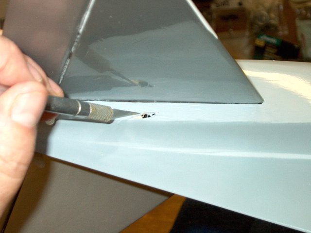
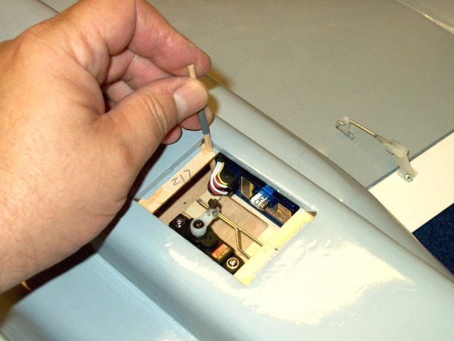
Remove the sleeve and use a knife to trim
the excess covering | |
Hole opening completed and the bare balsa
can be touched with some paint to match the fuselage
| |
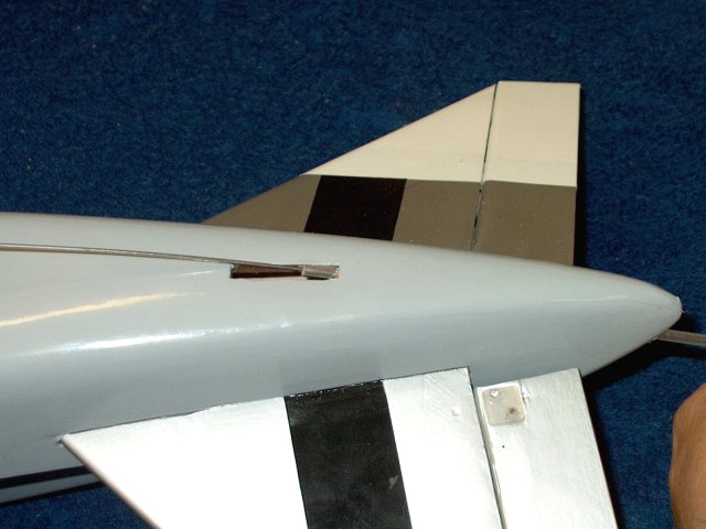
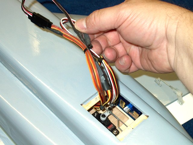
Re-install the pushrod sleeve from the
front opening | |
Trim the sleeve so it sits flush with the
fuselage side. IT may be easier and safer to mark it, then
remove it and trim against a hard surface so you don't damage
the fuselage | |
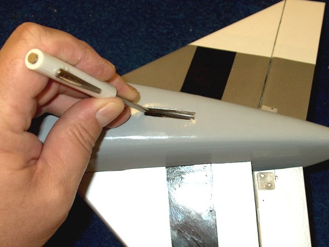
Remove and sand the sleeve to shape, then
clean out the hole for the pushrod | |
Move the plastic sleeve out of the way and
apply some epoxy to the hole, then move the sleeve in
place | |
Remove any extra epoxy with alcohol and
make sure the hole is clean | |
Sleve shown epoxied in place
| |
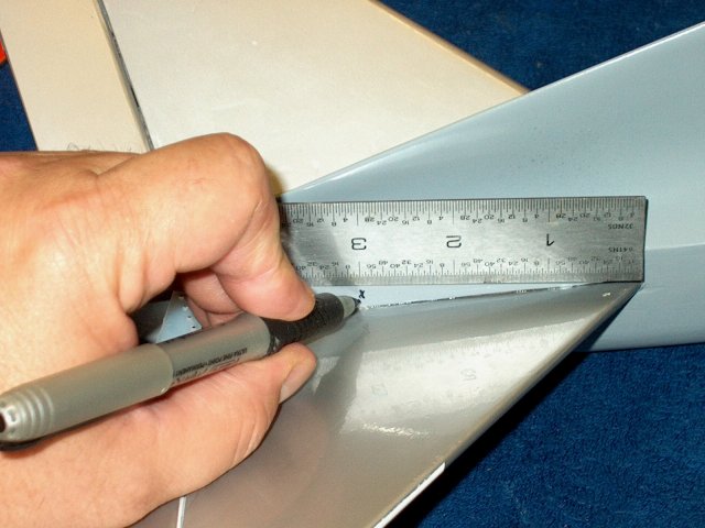
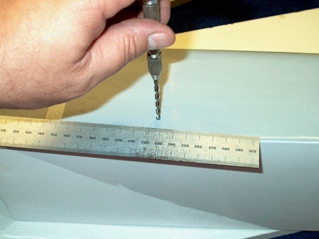
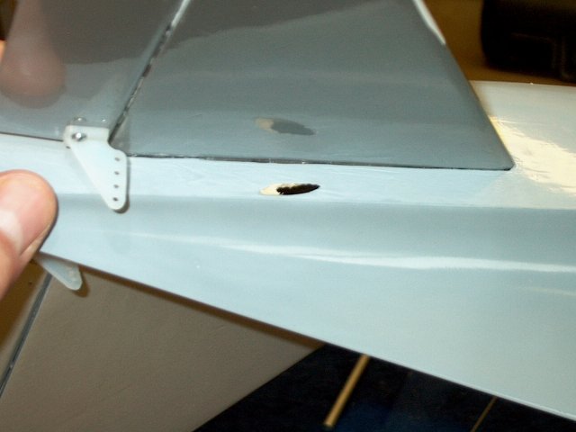
Measure back 3" from the leading edge of
the second stab | |
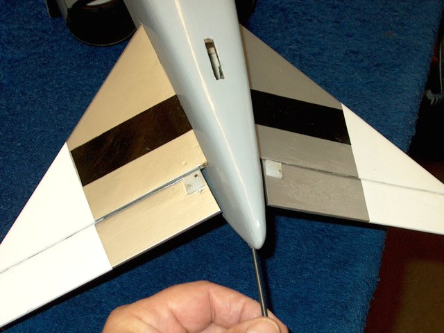
Start a 1/8" drill hole about 1 1/6" from
the top edge as shown | |
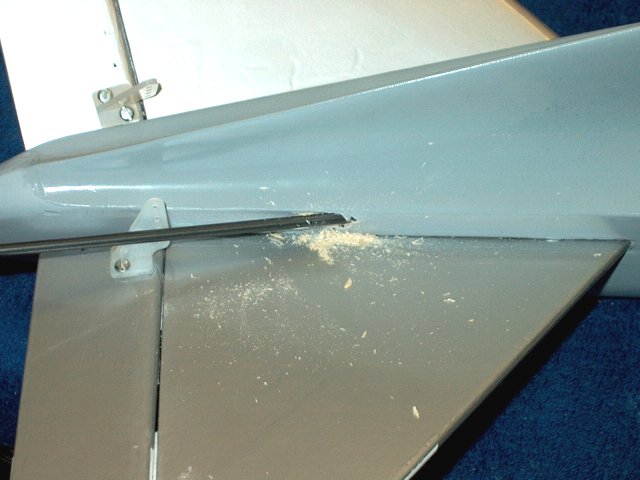
Turn the bit and use it to file a hole
toward the pushrod bracket that is located by the servo
| |
Install the pushrod from the rear
| |
Sand an angle on the end of the sleeve.
The will lay flush against the rear exit hole
| |

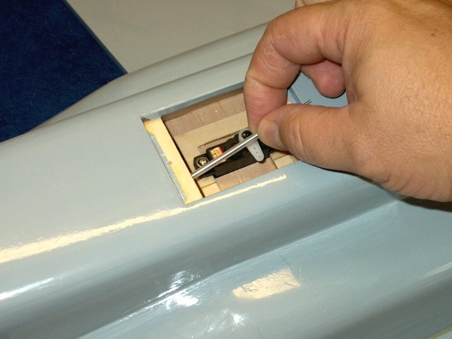
Install the sleeve in the bracket and run
it rearward, using the rod as a guide
| |
Pull the back of the sleeve away and add
some epoxy to the hole, then move the sleeve over the hole and
clean up any excess epoxy | |
Trim the extra length off the front of
each pushrod sleeve as shown | |
Use some epoxy at the base of each sleve
where they pass through the bracket
| |
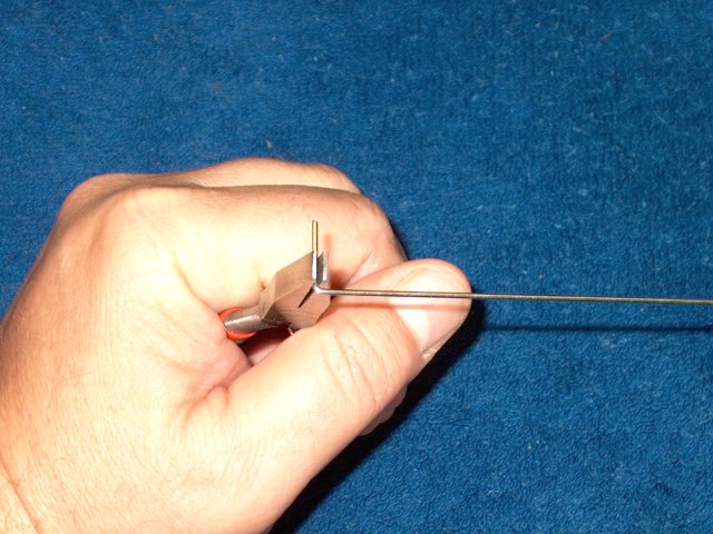
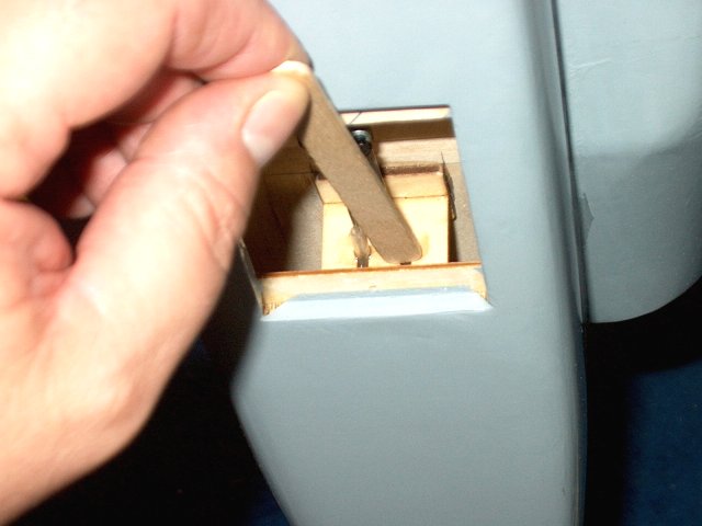
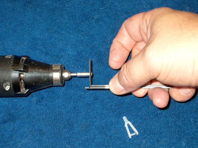
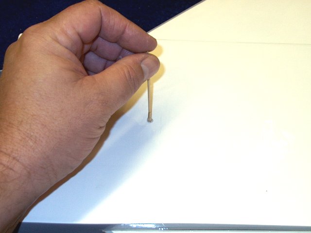
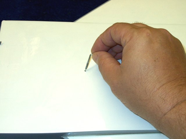
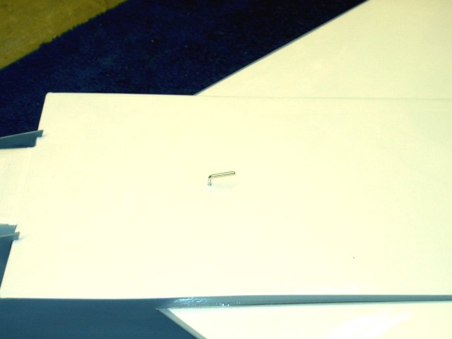
Bend a Z-Bend at the end of two of the
pushrods supplied in the kit | |
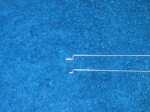
The pushrod at the top was supplied in the
kit, but it is too wide, as indicated by its height and this
can cause play. Cut the end off and make a tighter Z-Bend as
shown on the bottom rod | |
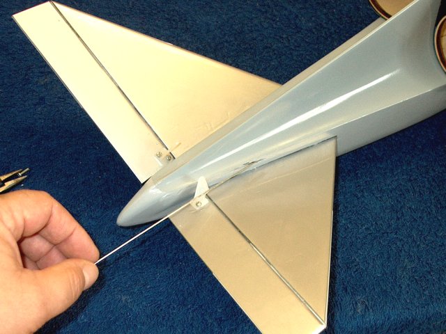
Install a rod from the rear
| |
Loosen one bolt on the horn, then twist it
sideways and install the pushrod in the outside of the
horn | |
Turn the horn in place and re-install the
screw. Make sure the pushrod is on the outside of the horn as
shown to prevent binding | |
Install the second pushrod in the same
manner as the first, making sure it enters the horn from the
side away form the fuselage | |
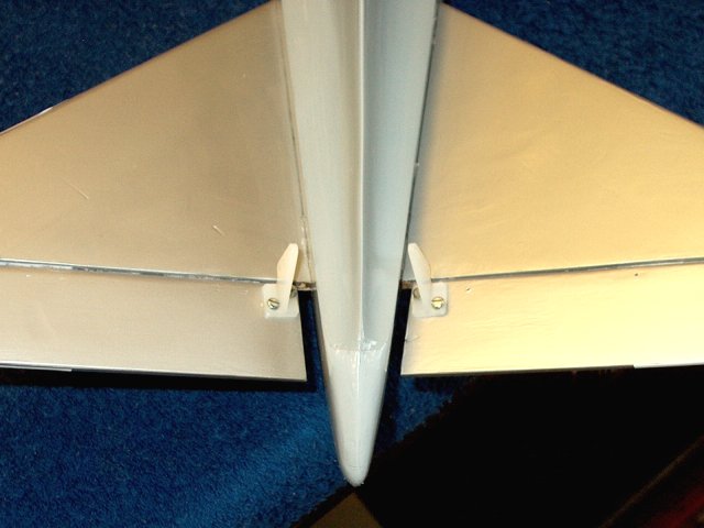
Both pushrods are installed in their
correct position as shown | |
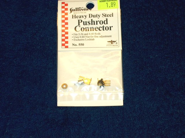
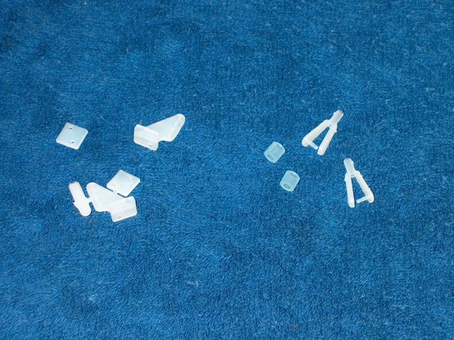
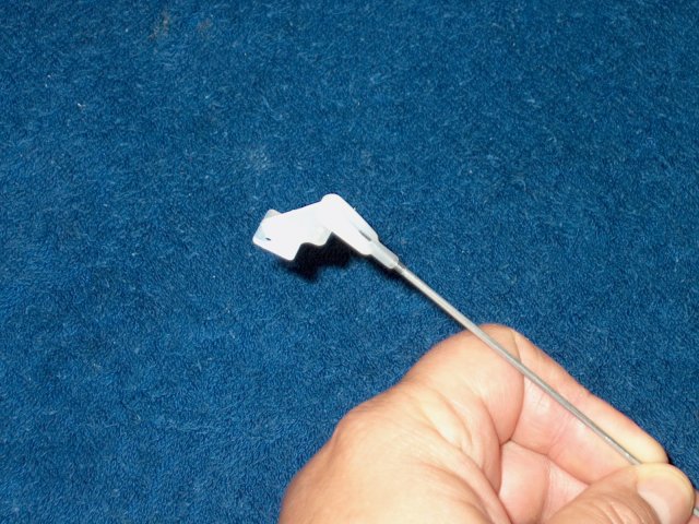
Use the following connector for the
elevator, as it has a wide enough hole and a threaded
base | |
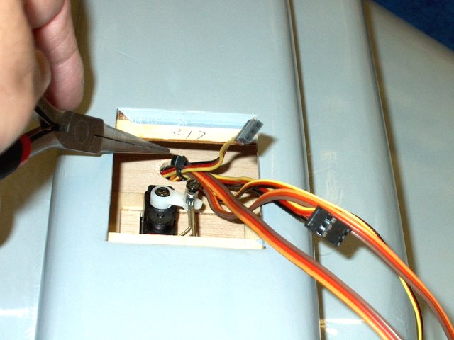
Bend the left side pushrod wire toward the
horn as shown | |
Finish bending the pushrod wire toward the
horn | |
Both wires run parallel to each other and
travel forward, right over the servo horn holes as
shown | |
Use clamps to hold both elevators at
center position | |
Make a mark on each wire for
cutting | |
Cut each wire at the mark, then sand/grind
away any burrs so they pass through the connector
| |
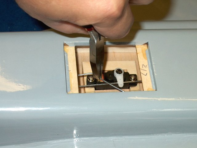
Remove the servo horn
| |
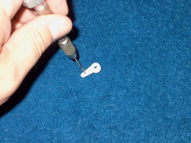
Drill a hole out with a 1/16" drill so the
connector will fit | |
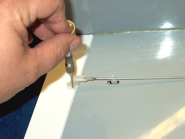
Install the pushrod connector
| |
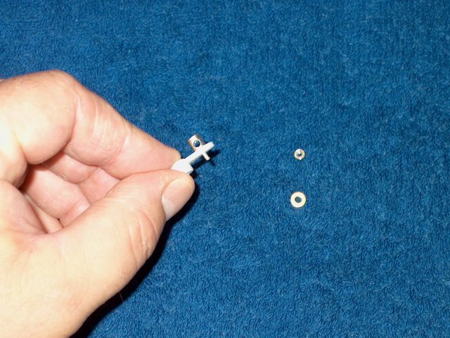
Use some CA to secure the nut to the
bottom of the connector | |
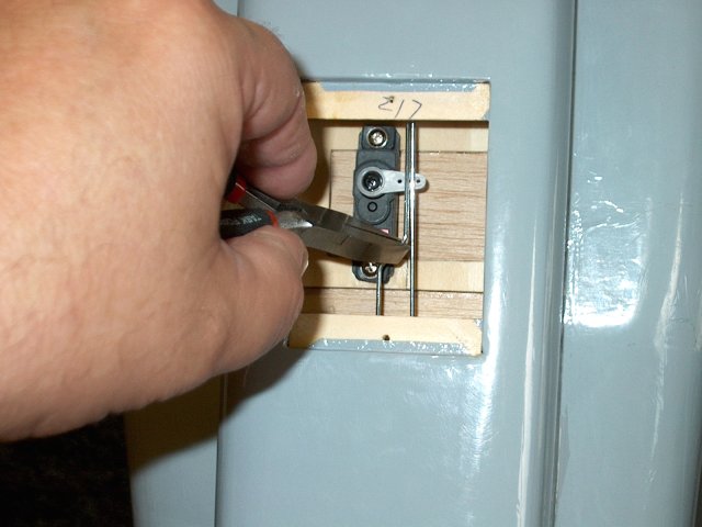
Slide the pushrod connector over both
pushrods as shown. Install the horn on the servo and secure it
with the horn bolt | |
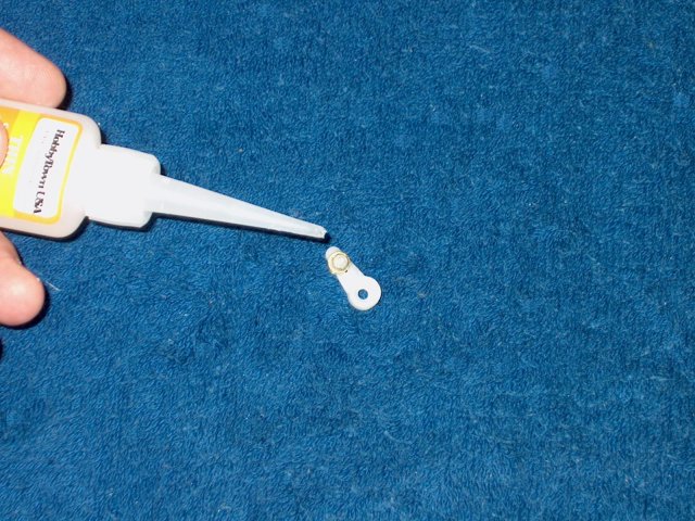
Appy some Loktite to the connector
bolt | |
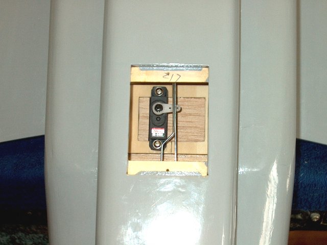
Install the bolt in the connector and
tighten. This completes the elevator assembly
| |
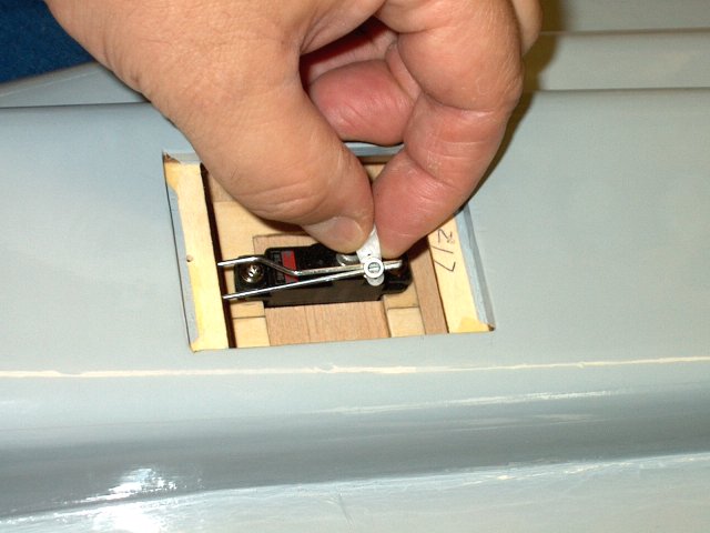
Install the hatch with the two supplied
screws | |
Low profile metal gear wing servos are
used for the ailerons | |
Remove the mounting ears from each of the
two servos | |
Use a knife and cut into the indented
servo well in the wing area | |
Iron the cloth out of the way on the inner
side and bottom | |
Place the servo over the opening and mark
its size on the wing | |
Use a ruler and draw the hole that needs
to be cut for the servo | |
Use a ruler and cut out the wing area at
the marks that were made | |
Remove the pieces that were cut and clean
out the servo well. Lightly sand the balsa bottom of the well
to smooth it out | |
Use a ruler or mixing stick to push out
the foam so the servo wire can be run
| |
Install the servo wire as shown
| |
Install the servo in the wing well and
trim the opening as necessary for a nice fit
| |
1/2A horns and 2-56 Clevis' were purchased
to replace the parts that were supplied. Once again, do not
use the wood horns in the kit | |
Medium to Thick CA is used to paint a thin
film on the bottom of the servo well in the wing
| |
Once dried, sand the area smooth with 320
grit and clean up the dust with denatured alcohol
| |
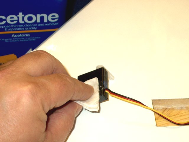
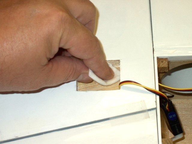
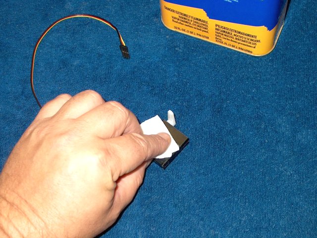
The bottom of the servo is cleaned with
acetone | |
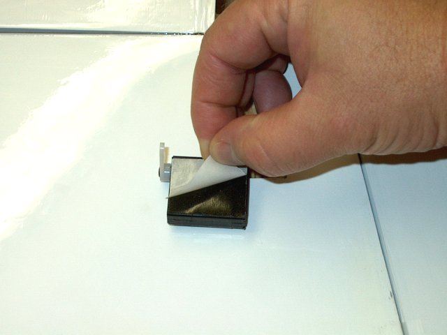
A piece of servo tape is applied to the
bottom of the servo area that was just cleaned. DO NOT REMOVE
the bottom servo tape backing yet | |
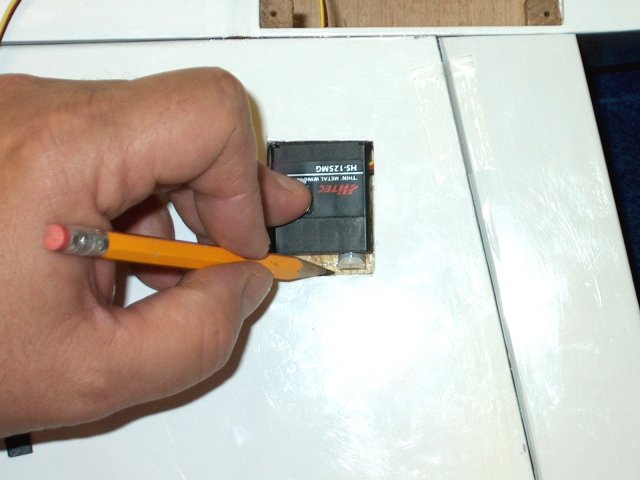
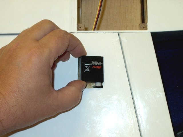
The servo is inserted into the well in the
wing and marks are made 1/8" beyond each side of the servo arm
center hub to allow for travel | |
A 3/16" wide slot is cut out for the servo
arm as shown | |
Remove the excess material and
balsa | |
The servo is installed and held in place
with masking tape | |
The servo arm is checked for clearance and
travel. Elongate or widen the slot if necessary
| |
Remove the servo arm, then center the
servo using a tester or your receiver
| |
Install the arm to the center position and
use the servo bolt to hold it in place
| |
Remove the backing from the servo
tape | |
install the servo in the wing well, making
sure to position it correctly. You can hold on to the arm from
the other side while making small adjustments
| |
When centered, press the servo firmly in
place | |
The servo arm should be centered on the
other side of the wing as shown | |
Servo installation is now completed
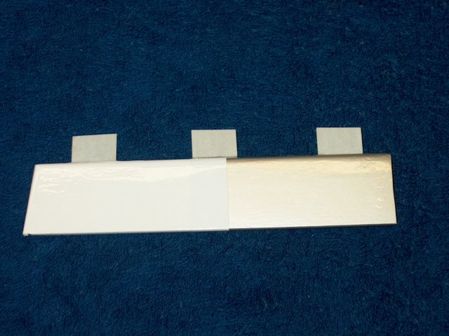
| |
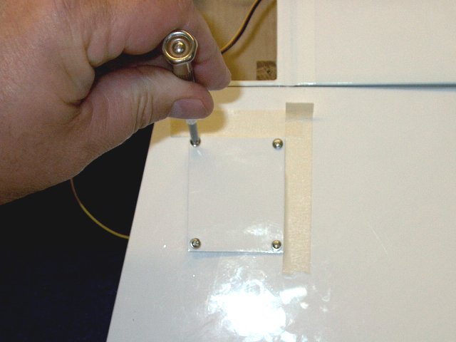
Two servo covers are made from 1/32" ply
and cut to a size of 2 1/8" x 1 3/4". Thin CA is applied to
the corners on both the top and bottom to prevent splintering
when drilled for mounting screws | |
Sand the corners on both sides to a smooth
finish | |
The servo hatch covers are covered with
material to match the bottom of the wing
| |
Make punch marks about 1/8" from each
corner for both servo hatch covers | |
Use a 1/16" drill to open the holes for
the screws | |
Mounting screws included with the servos
are used for the covers and threads are started before
mounting | |
Cover position is marked by centering it
over the hatch and using a piece of tape to help mark
alignment. Do this for both directions
| |
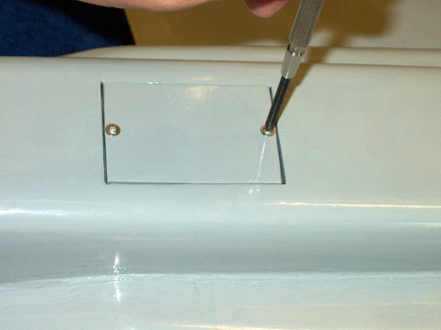
The cover is placed in position, then the
screws are used to tap threads into the balsa. Once completed,
remove the cover and touch each thread in the wing with a drop
of CA to strengthen the hole and allow the CA to dry
| |
Final installation of the Servo Hatch
Cover is shown | |
Another set of 1/2A horns and Clevis' will
be used for the Ailerons | |
The second aileron well is measured and
cut so the servo fits | |
The bottom of the servo well is sanded,
then a mixing stick is used to clear the path for the servo
wires | |
The servo fit is tested, making sure there
is enough clearance for the horn | |
The bottom area is painted wit a thin coat
of CA, then sanded smooth | |
Measurements are drawn for the horn exit
hole, then the hole is cut out with a sharp knife
| |
The servo is centered using a tester or
your receiver. Once centered, install the horn and retaining
washer/bolt | |
Clean the bottom side of the servo with
acetone | |
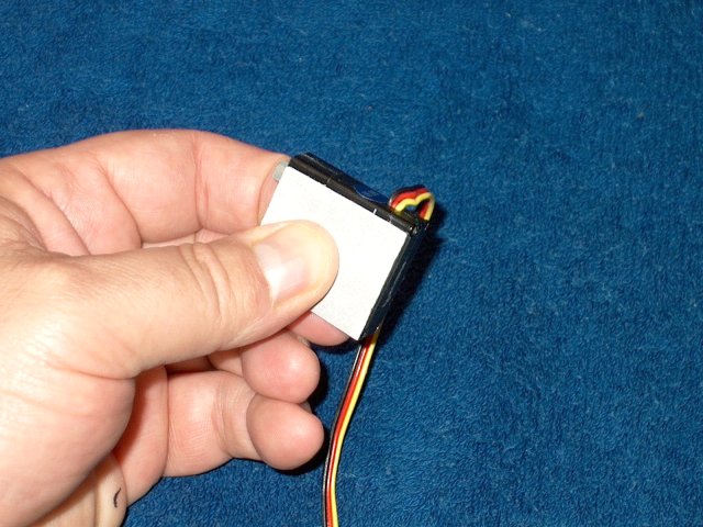
A piece of servo tape is installed on the
servo | |
The servo tape backing is removed
| |
The servo is installed, making sure the
horn is centered in the slot you cut. Press down to insure a
good bond | |
Install the screws on the second
cover | |
The cover is installed in place over the
servo | |
Aileron servo installation is shown
completed | |
Center marks are drawn on the six very
nice aileron hinges supplied in the kit
| |
Install three hinges in an aileron as
shown | |
Place the aileron over its location and
mark the hinge locations on the fuselage. make sure there is
clearance for free movement on both sides
| |
Open the slots with a knife if
needed | |
Install the Aileron in place. Pins are
used to prevent the hinges from moving during install
| |
Thin CA is applied to permanently mount
the aileron. Make sure there is enough throw without binding
before gluing the hinges in place | |
Excess glue is wiped off and CA is applied
to the hinges from the other side of the wing
| |
Prepare the second Aileron
| |
install the retaining pins
| |
Mark the hinge locations, open them up if
necessary, then install the aileron
| |
Flex the aileron downward to insure ample
throw without binding, then glue the hinges in place on both
sides with thin CA | |
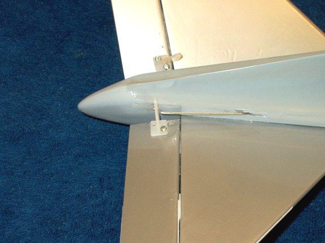
A mark for the Aileron horn is made as
shown. Keep the ruler parallel to the side of the
fuselage | |
A second outer mark was made so the
aileron horn would fit between them
| |
Threads are marked to be shortened on two
2-56 pushrods | |
Pushrods are cut to length as shown
| |
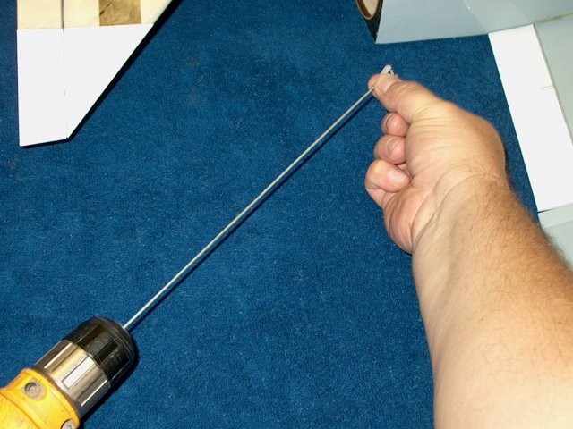
Then end of each pushrod is screwed on the
plastic clevis. A drill makes this go faster
| |
the clevis is locked on the horn
| |
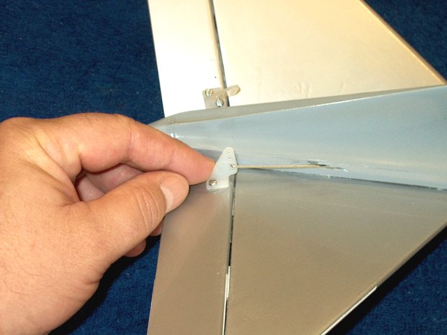
The horn is positioned, then a drill hole
is made | |
A bolt is installed in the first hole to
keep the horn aligned while the second hole is drilled
| |
Both bolts are installed for the horn. Be
sure not to over tighten | |
The excess bolt is cut short on the
underside, then capped with thick CA for safety
| |
The second horn is installed in the same
manner. Note that longer, 3/4" x 2-56 bolts need to be
purchased and used as the ones that came with the clevis' are
too short | |
cap the second set of bolts with a mound
of CA | |
Install a clevis on an Aileron horn, then
center the servo and clamp the Aileron as shown so it is held
to center. Mark the hole location for the z-bend
| |
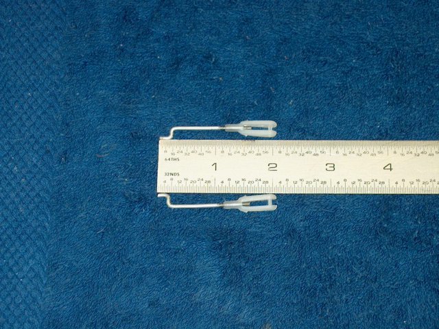
Make two identical pushrods as
shown | |
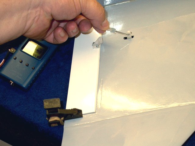
Install each pushrod and adjust while the
aileron is clamped to center and the servo is set to center
position | |
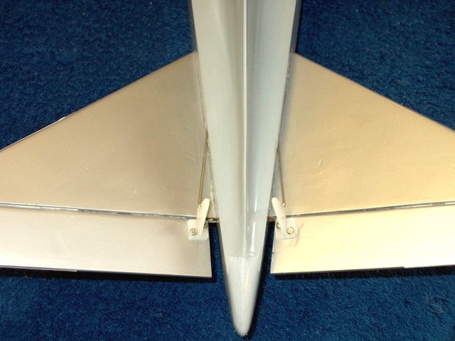
Aileron installation shown
completed | |
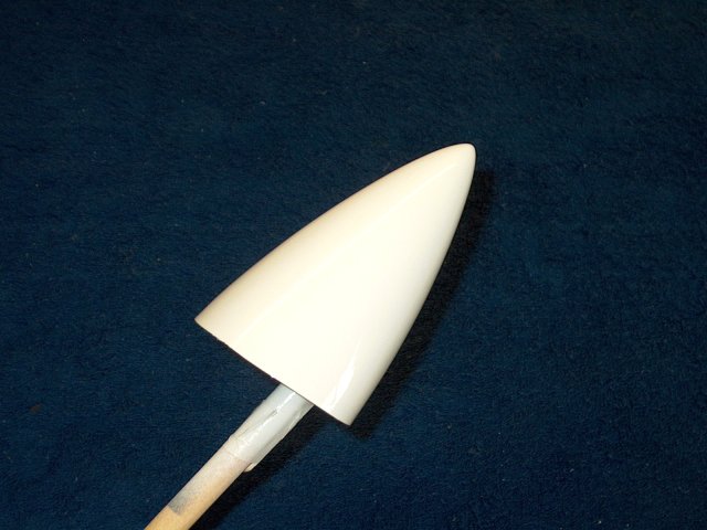
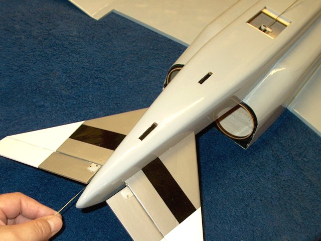
Nosecone was painted white for a more
scale appearance | |
The rear motor area of the fuselage is
touched up with flat black paint | |
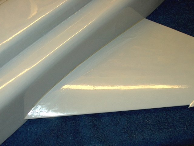
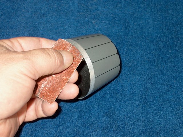
The tailcones were sanded on the outside
and at each end to smooth them out | |
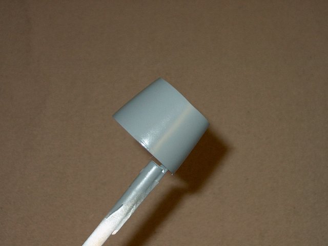
Each tailcone was painted with flat dark
gray Testors Model Masters spray paint
| |
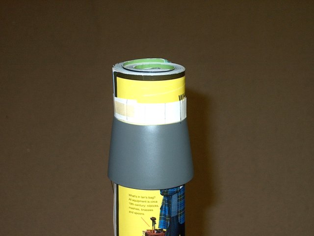
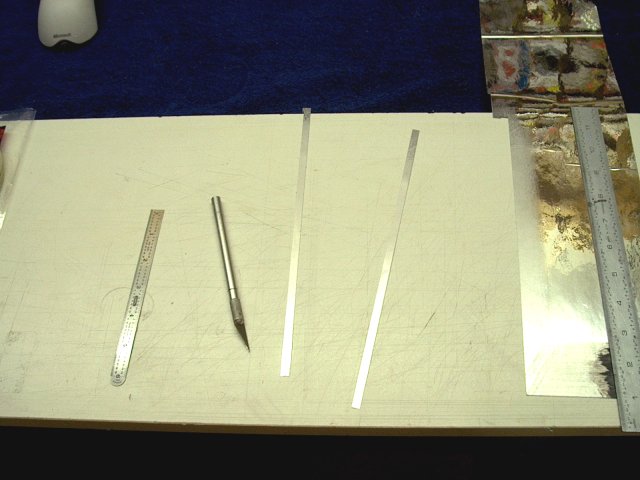
A magazine was used to hold the tailcone,
then a piece of paper was wrapped around and taped. It was
then removed, folded in half and then each half was folded in
thirds and pencil marks were made at all 12 points. It was
then slid back over the magazine as shown
| |
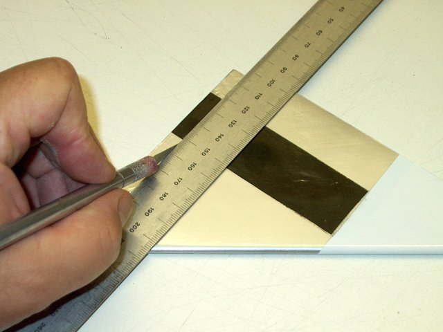
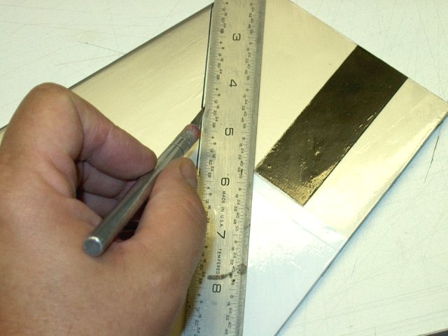
Thin strips of Monokote were cut and
applied, then the ends were trimmed
| |
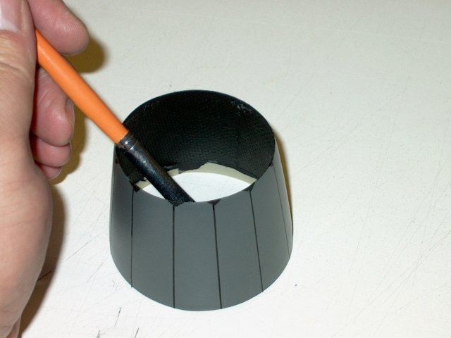
The inside of each tailcone was painted
flat black | |
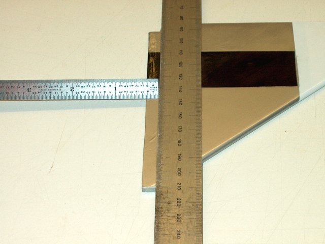
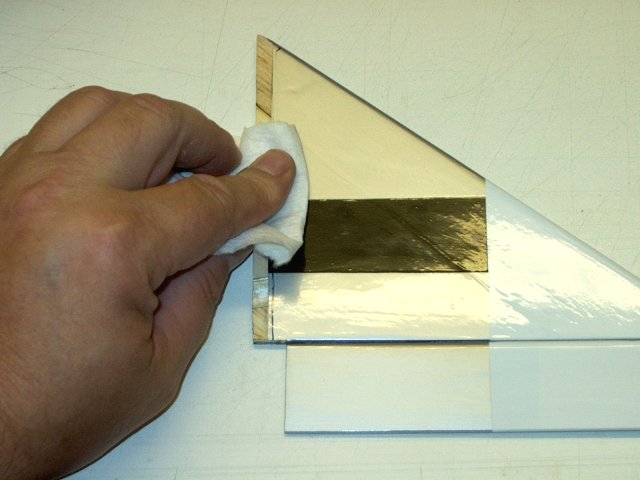
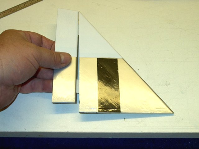
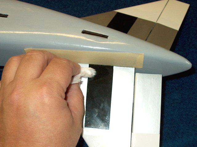
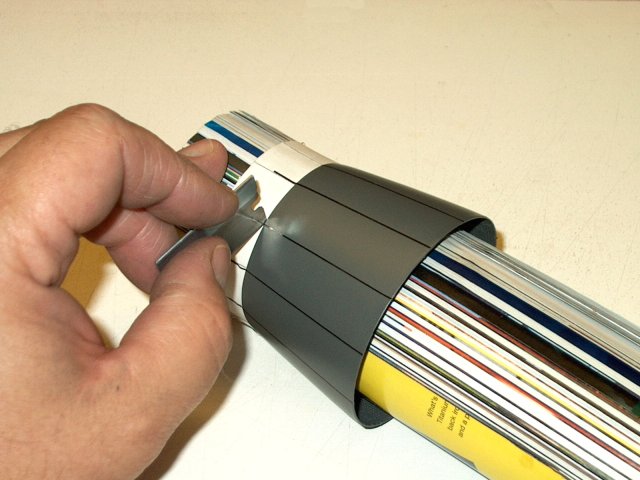
A section of chrome self stick Monokote
was lightly sanded, then two 1/4" wide strips were cut about
10" long | |
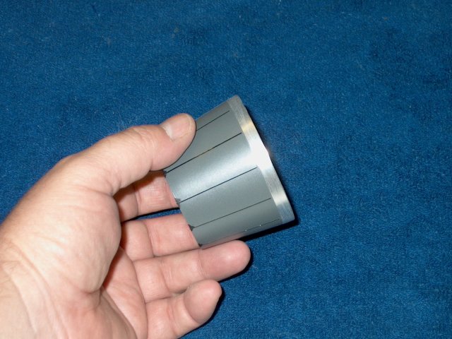
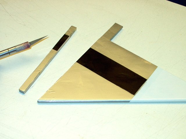
The chrome strips were applied to the
tailcones as shown for a more realistic look
| |
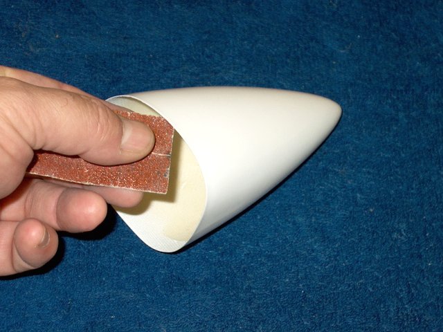
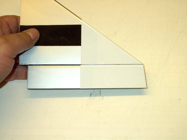
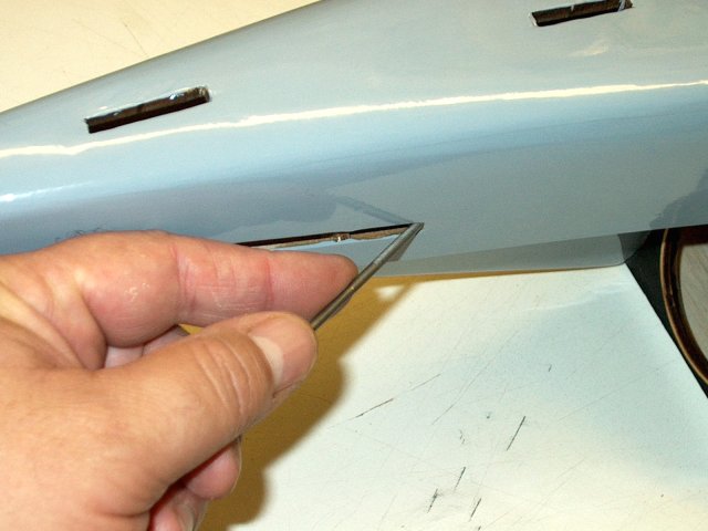
The inside lip of the nosecone is roughed
up with 60 grit sandpaper for better glue adhesion
| |
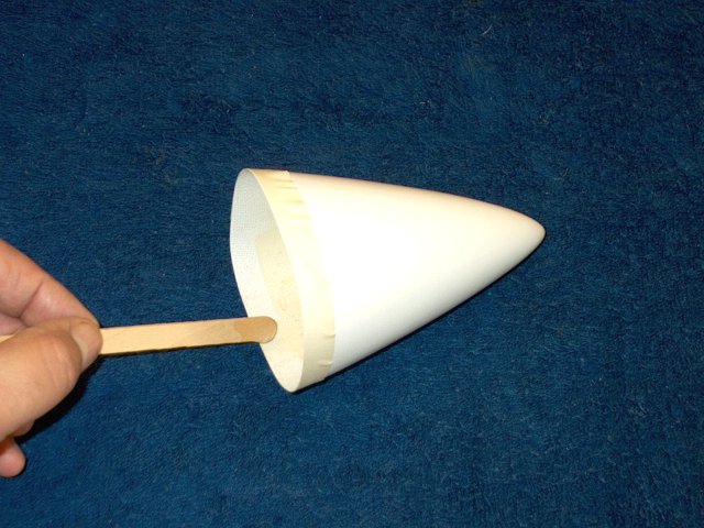
Tape is used to prevent overspill of glue
that could ruin the finish. Five minute epoxy is applied to
the inside lip of the nosecone | |
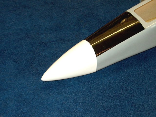
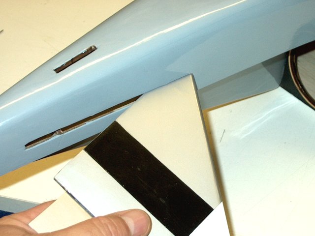
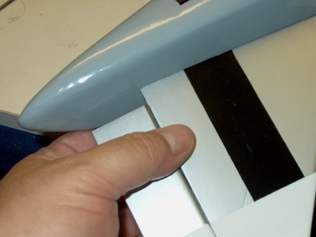
The nosecone is installed on the front of
the fuselage and held vertically until the glue set
| |
The inside lip of each tailcone is roughed
up with 60 grit sandpaper for better glue adhesion
| |
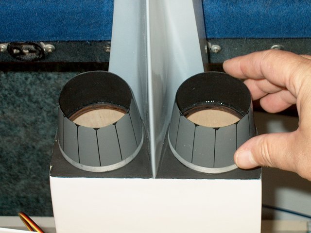
Epoxy is applied to the inside of each
tailcone and they are installed as shown
| |
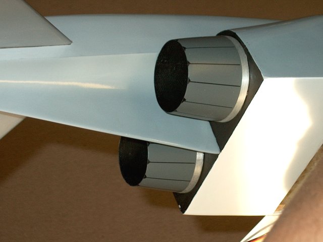
Tailcone installation completed
| |
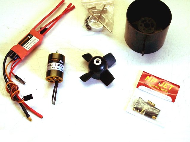
Parts required for each power plant
| |
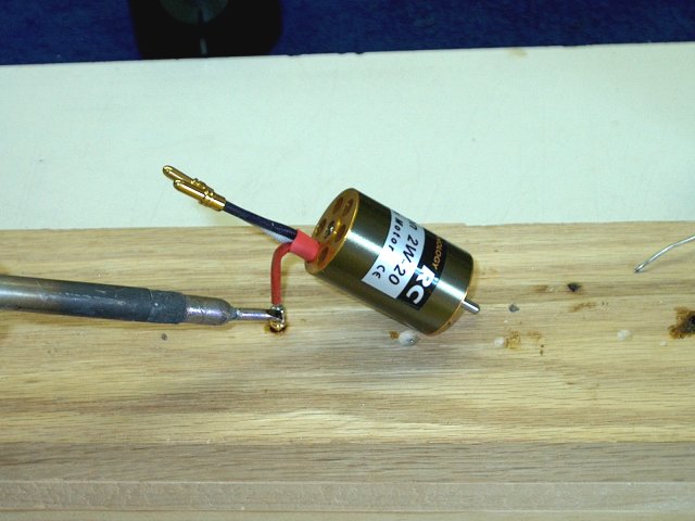
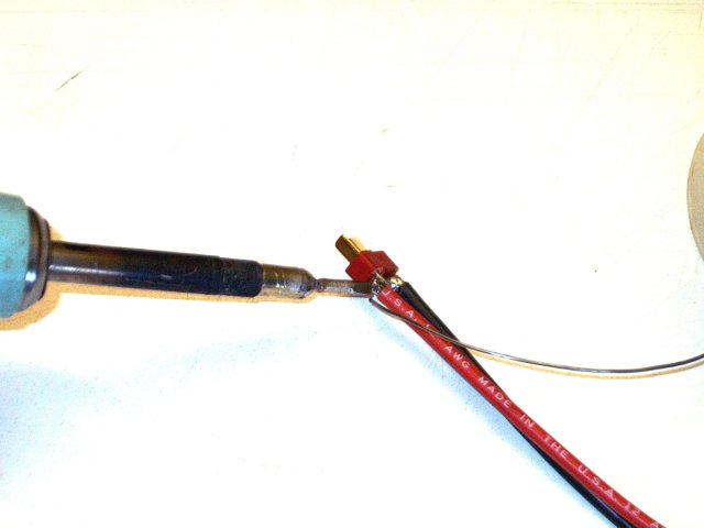
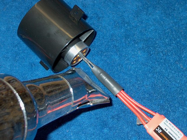
You will be making two power plants, so do
them together. Plugs are soldered to each motor
| |
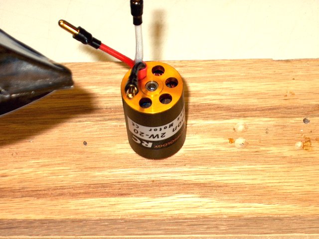
Heatshrink is placed on each wire as
shown | |
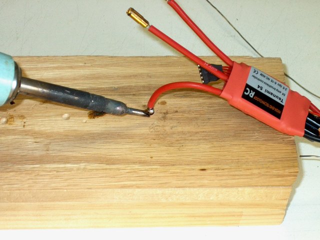
Sockets are installed on each ESC
| |
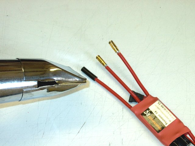
Heatshrink is applied to prevent shorting
of the leads | |
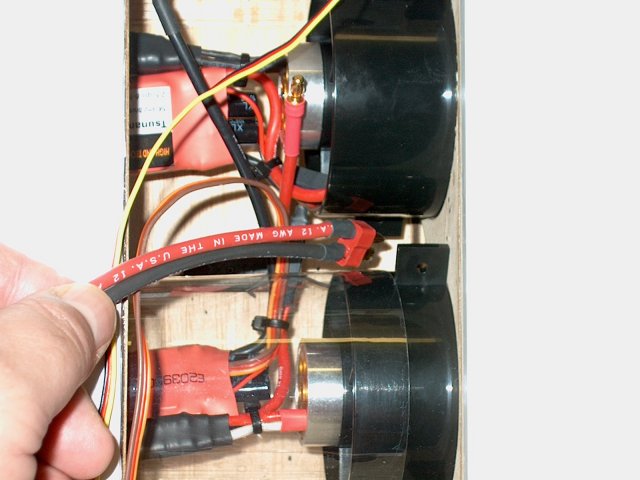
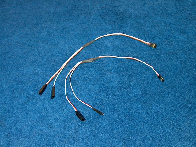
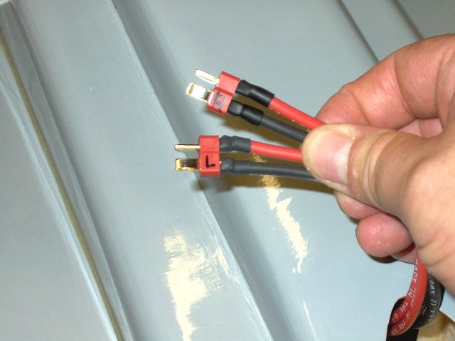
A Power wire is made for each battery
connection, with one end connecting to the ESC, while the
other end has a Deans Ultra plug installed for each
battery | |
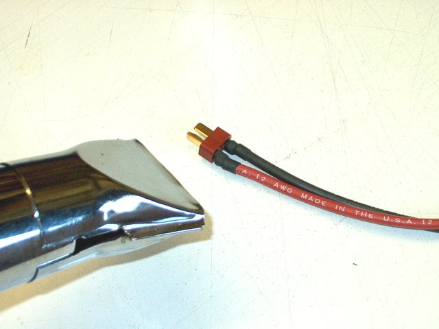
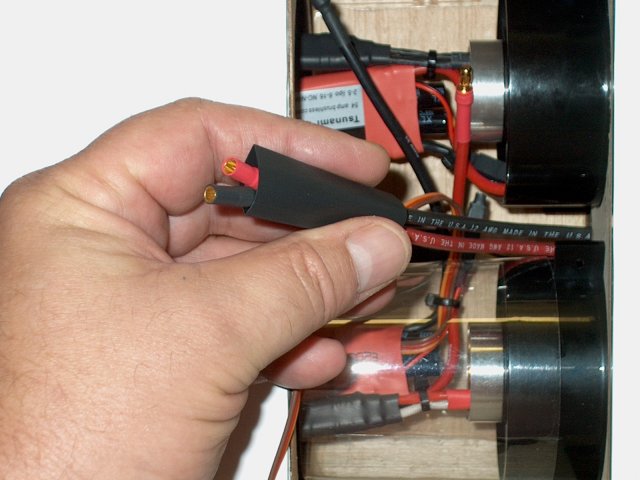
Heatshrink is installed on each
plug | |
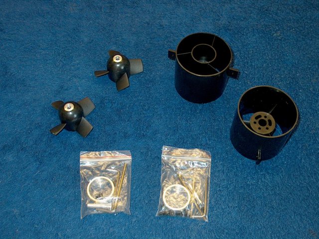
Two fan units are assembled at the same
time. HET-RC fans were used, so if you use another type of
fan, follow your manufacturer's assembly instructions
| |
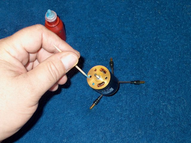
Loktite is applied with a toothpick ONLY
to the threads on the motor. DO NOT apply Loktite anywhere it
could come into contact with the fan as it can attack the
plastic in the housing. Never apply Loktite to the bolt
threads | |

Clean up all excess Loktite. Green Loktite
is prefered as it is plastic safe | |
Motor alignment is temporarily
checked | |
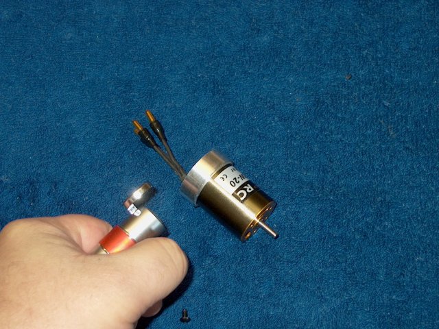
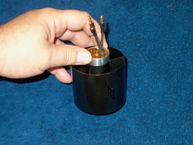
The supplied heatsink from the fan unit is
installed on the back of the motor. You may have to heat it
with a torch lighter if the fit is too tight
| |
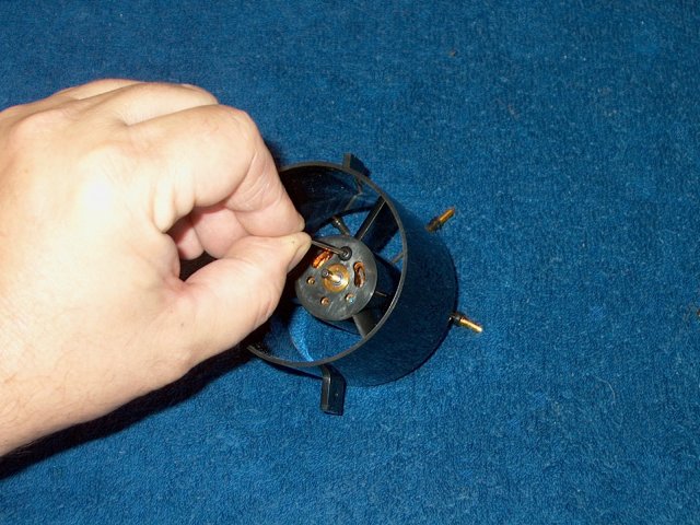
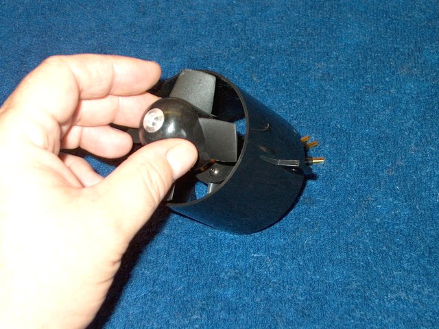
Install the motor in the fan
assembly | |
Push down on the heatsink so it sits flush
on the back of the motor housing. The inside lip on the
heatsink fits inside the rear of the plastic motor
shroud | |
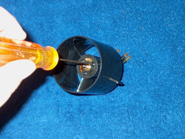
Tighten the 3.5mm motor mount bolts
| |
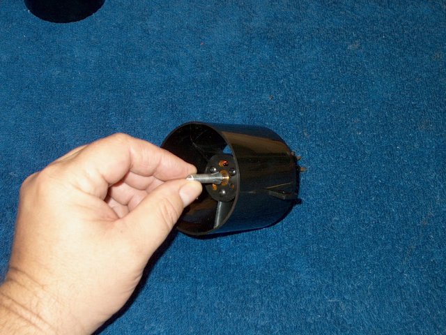
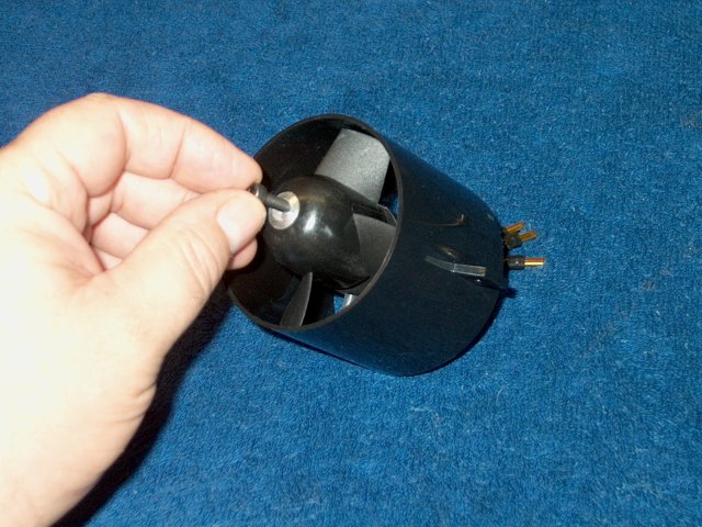
The shaft adapter is installed over the
motor shaft | |
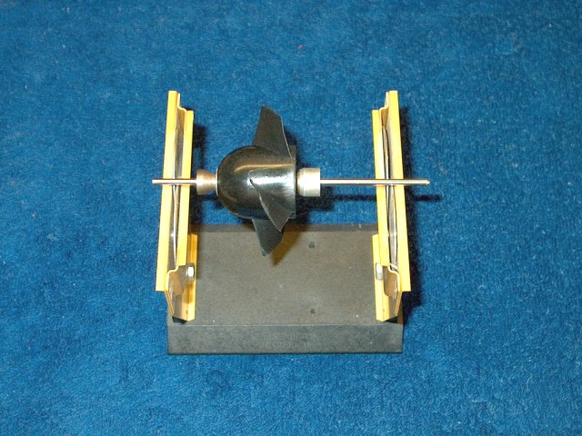
Check each fan rotor for balance. HET-RC
fans come pre-balanced, but I had one that was just a bit
off | |

Apply Loktite to the threads of the shaft
adapter | |
The rotor is placed over the shaft
adapter | |
The retaining bolt in installed
| |
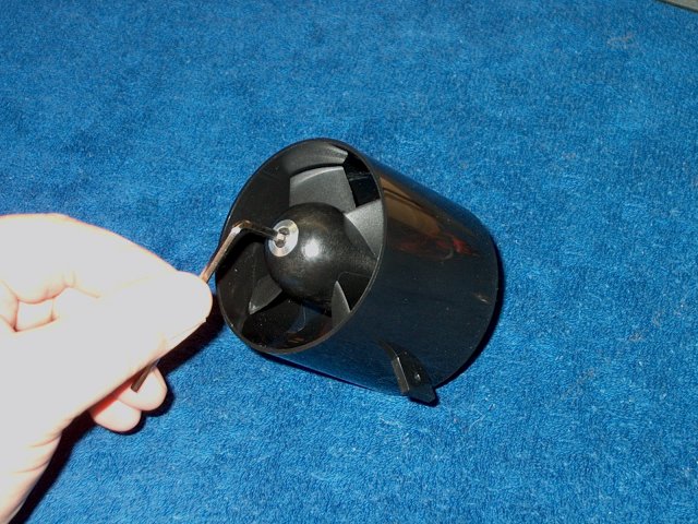
Hold the rotor and tighten the shaft
adapter bolt. Make sure the inside back of the fan rotor is
spaced far enough away from the housing so it doesn't bind
when tightened. This completes the Fan Unit assembly
| |
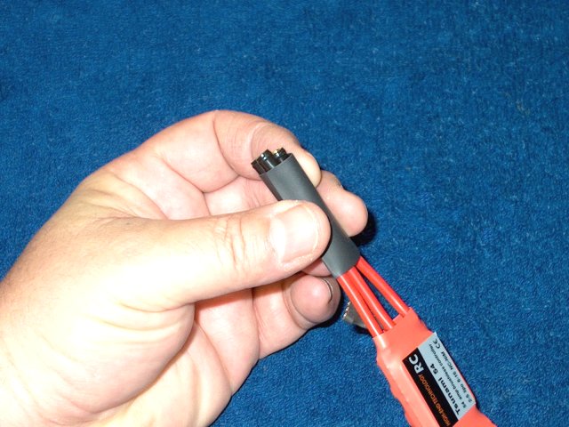
A 1 1/2" long piece of heatshrink is
placed over all three ESC leads | |
The motor is plugged in to the ESC leads
and the heatshrink is used to hold them together
| |
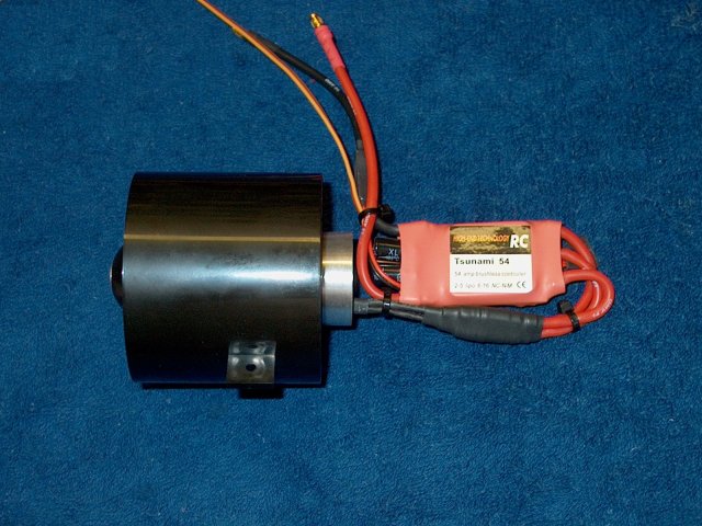
Tie wraps are used to dress the cabling
for each fan unit | |
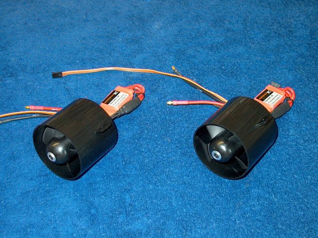
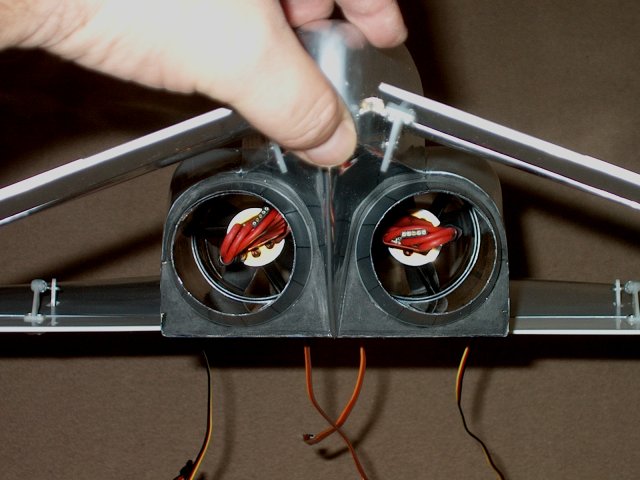
Both Fan units are shown completed and
ready to install in the fuselage | |
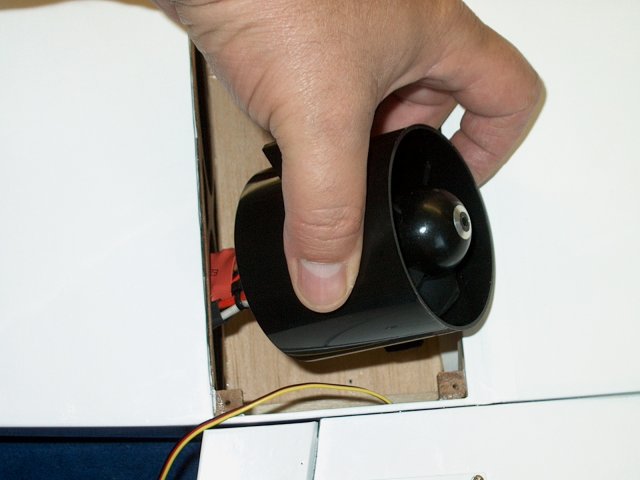
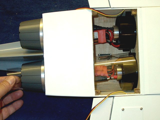
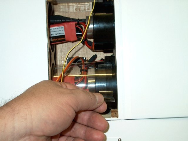
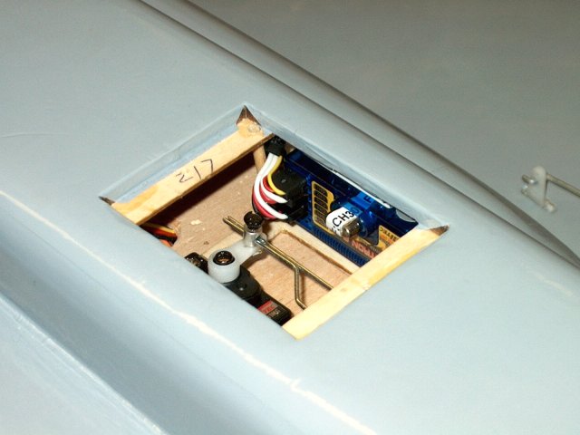
The ESC isinstalled in the rear of the
fuselage so the fan will clear the opening
| |
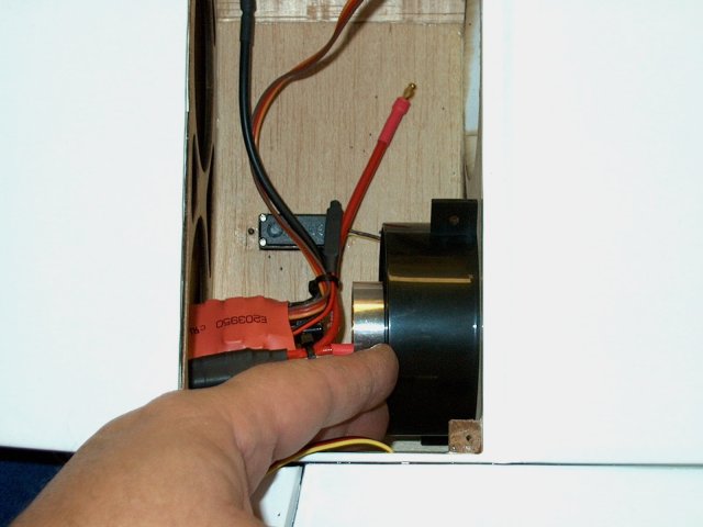
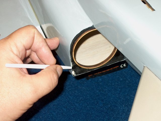
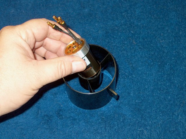
The fan is installed in the fuselage
intake duct | |
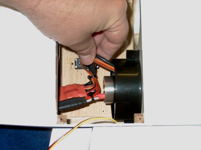
Wires are temporarily run inside the fan
to ease assembly of the exhaust ducts
| |
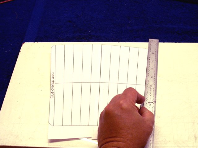
A thrust tube pattern was printed from the
HET-RC site and used to cut out the pattern for each thrust
tube sheet that was supplied in the kit. The tail was left
extra long so it could be custom fit
| |
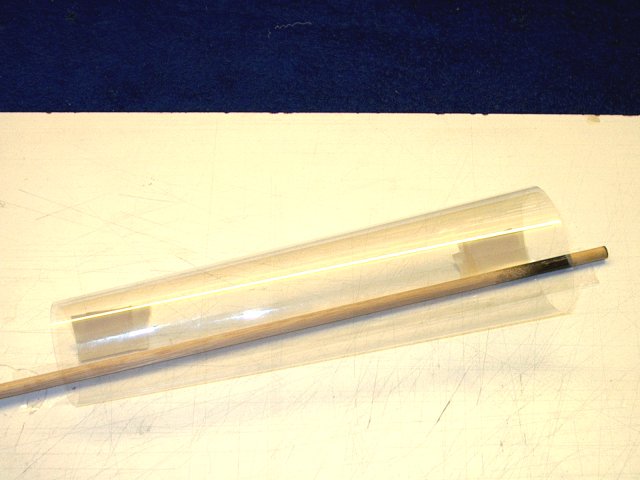
The thrust tube shown cut from the
pattern | |
It is inserted through the tailcone to the
fan area | |
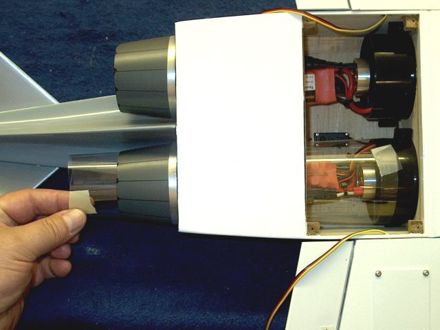
Masking tape is used to temporarily hold
it in place tight against the back of the fan and expanded
against the inside of the tailcone at the rear
| |
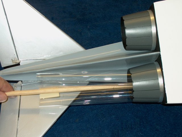
A stick helps fold the tube for easy
extraction | |
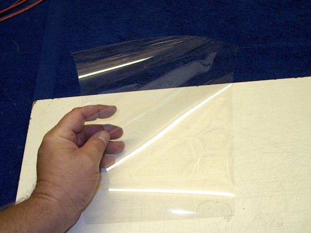
1" wide strips of clear packing tape are
used inside and out to permanently seal the seam and a stick
is used to push the tape down on the inside
| |
The thrust rube is inserted in the
fuselage and a mark is made for the location of the ESC
wires | |
The tube is removed and two washers
sandwich the tube and are used as a cutting guide for a wiring
exit hole | |
The thrust tube is inserted back in the
fuselage and the wires are fed through the hole
| |
The thrust tube is then slide on the rear
of the fan unit | |
Power wires Deans Connector end is fed
through the hole to the cockpit area
| |
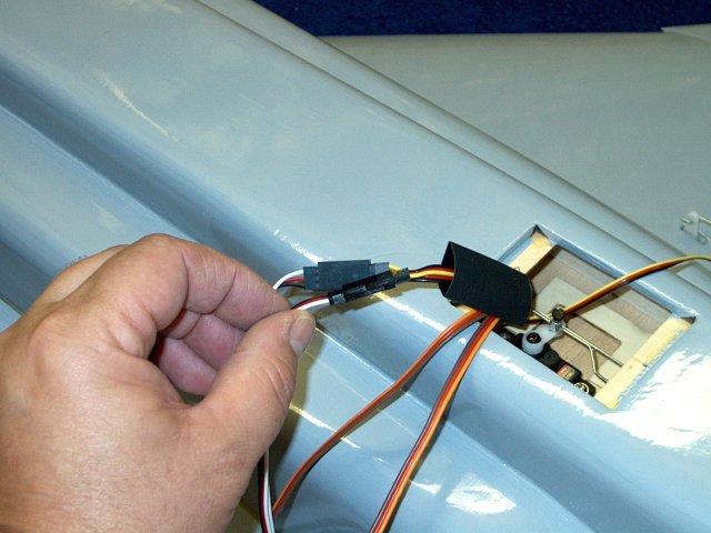
A piece of heatshrink is slid over the
power wires | |
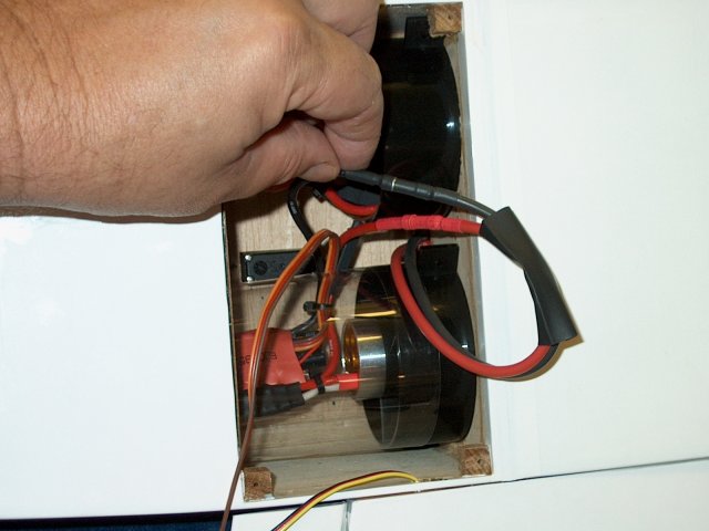
The power wires are connected to the ESC
connectors | |
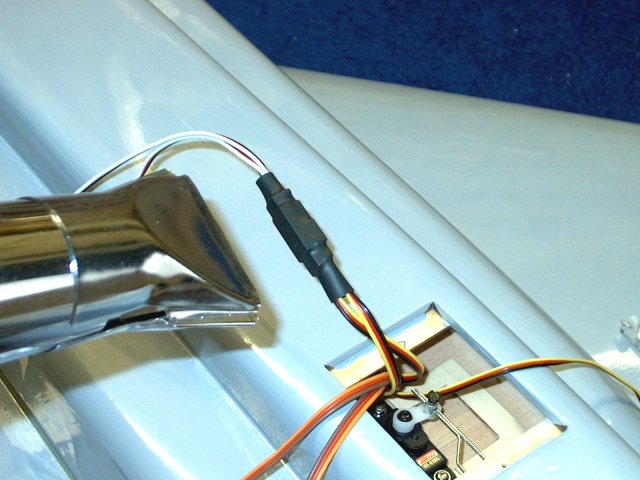
A tie wrap is used to align the
connectors, then Heatshrink tubing is installed over the two
connectors | |
A 3/4" piece of packing tape is used to
bond the thrust tube to the rear of the fan shroud
| |
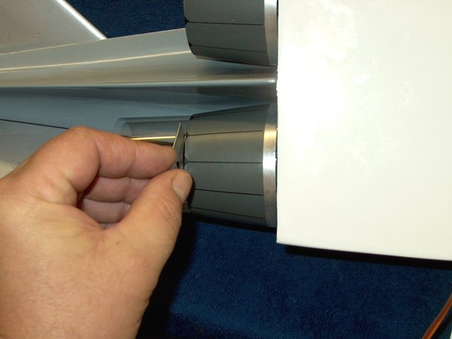
The thrust tube is cut flush to the rear
of the tailcone | |
The second fan thrust tube is built and
installed just as the first | |
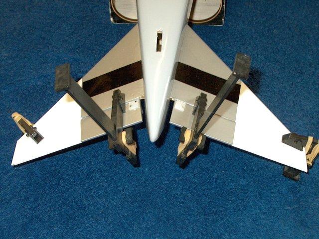
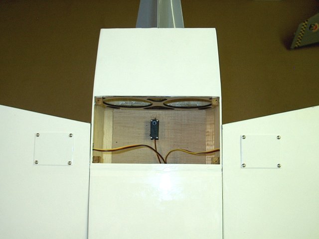
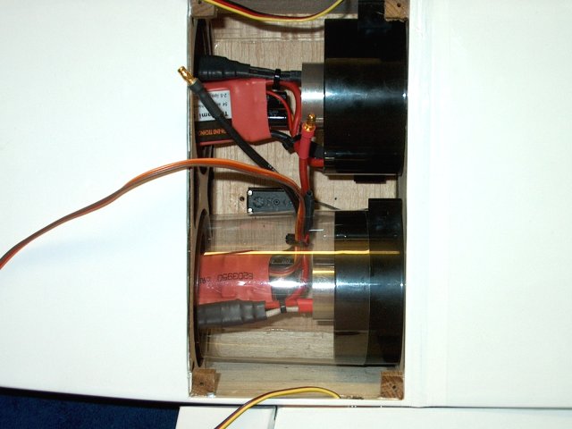
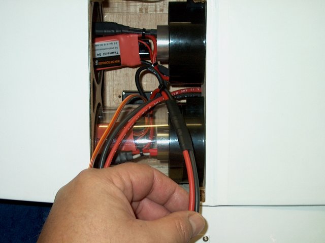
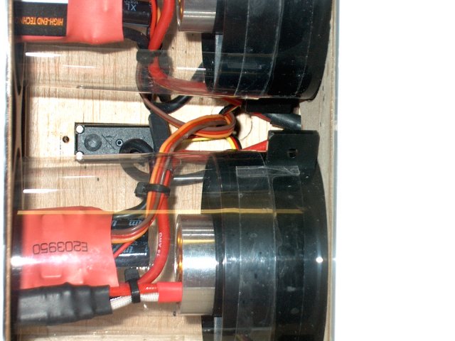
Rear of fuselage showing completed fan
assemblies and thrust tubes | |
The hatch is temporarily installed to
check for fit | |
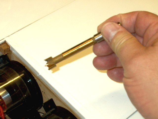
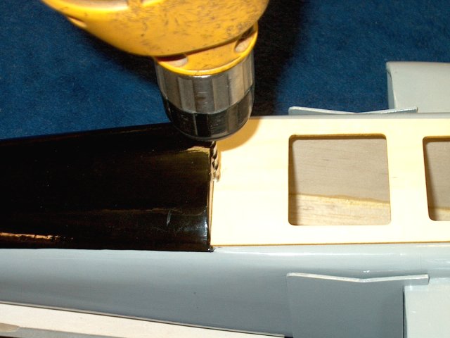
A 1/2" boring bit is used to cut an exit
hole for the servo wires. You can also use a sharp
knife | |
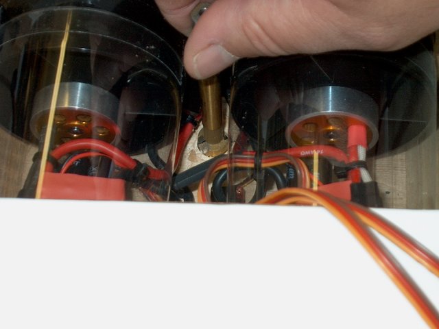
Cut the hole between the fans as
shown | |
Excess balsa cap is removed from the top
side in front of the Elevator servo
| |
Feed the servo wires through the
hole | |
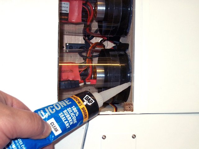
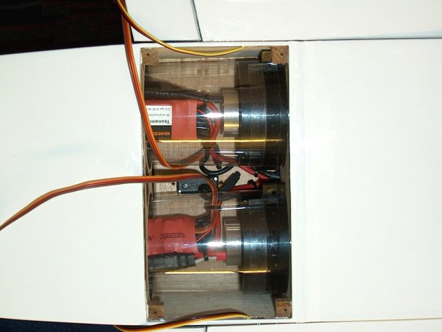
Clear silicon is used to bond the fan
units in place. It can be cut away if access is ever
needed | |
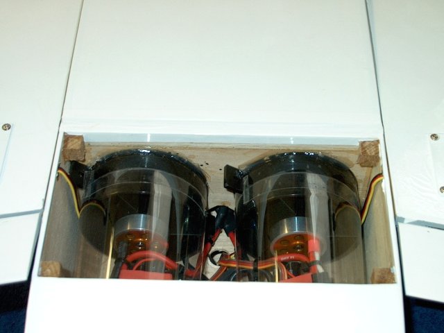
Fans are now fastened to the
intakes | |
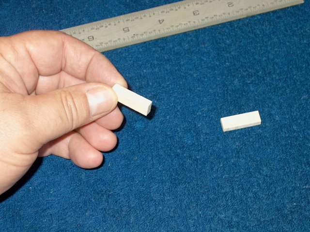
Two balsa strips that are 1" x 3/8" x
3/16" thick were made to support the cover, which was bowed in
the middle | |
Balsa strips are glued in place with CA to
help hold flush the bowed center of the hatch cover
| |
The hatch cover is installed
| |
A tie wrap is used to anchor the bottom
entrance of the servo wires | |
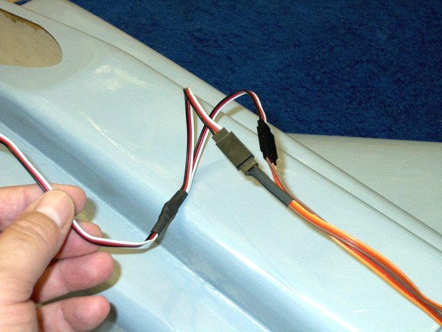
Two "Y" connectors are required, one for
the Aileron servos and one for the ESC's
| |
The two Aileron servo leads are
installed | |
A large piece of heat shrink tubing is
used to prevent the connectors from coming apart
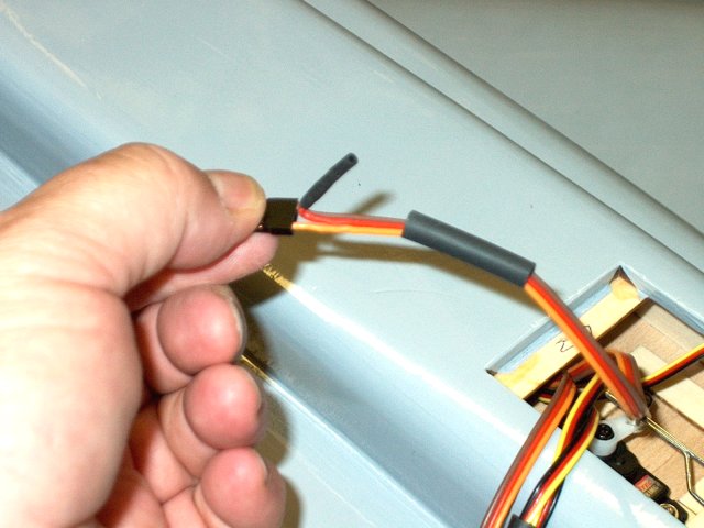
| |
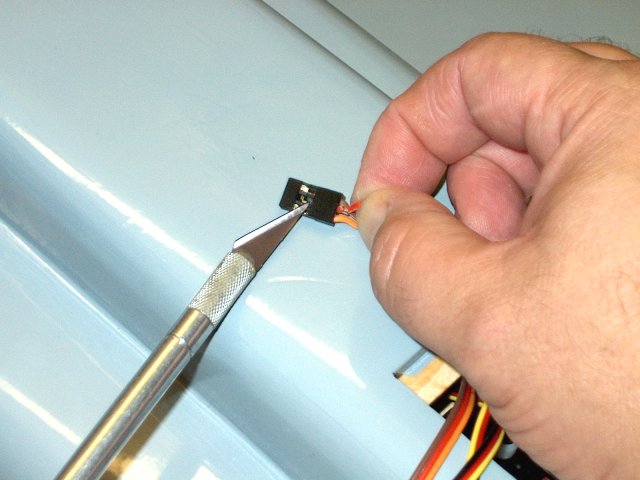
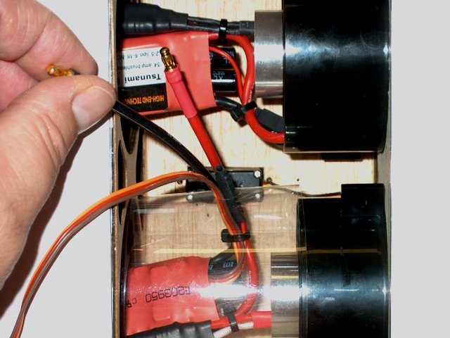
The center red wire lead is removed from
only one of the ESC's as the receiver needs to only be powered
by one ESC. Use a knife as shown to pry up the end of the
plastic clip that is holding in the connector
| |
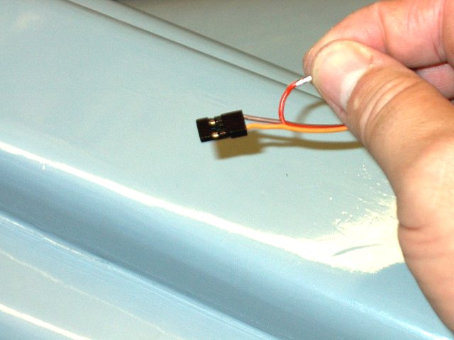
The red wire has been removed
| |
Heat shrink is used to cover the connector
so it won't snag or become damaged | |
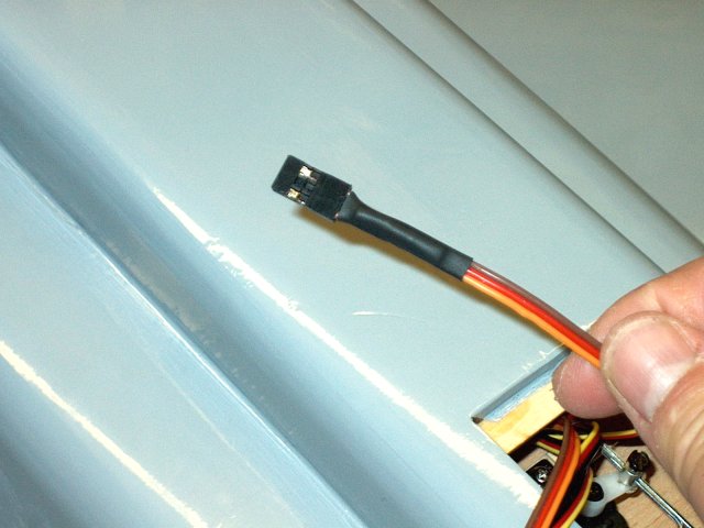
Another piece of heatshrink is used to
dress up the wire | |
Connect both ESC's to the other "Y"
connector | |
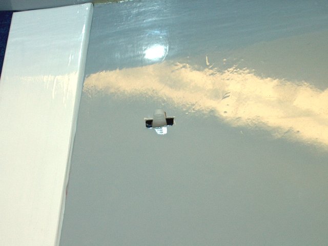
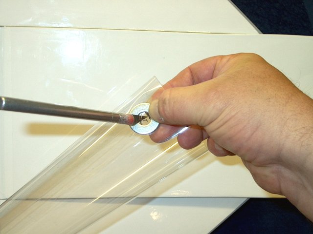
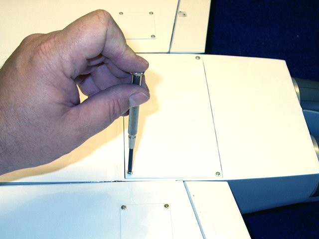
The receiver antenna will exit the bottom
rear of the fuselage, so a small punch is used to mark the
location | |
A 1/8" long drill is used to make a
hole | |
The drill should just exit the rear slot
as shown | |
A wire is used as a guide and the antenna
sleeve is installed | |
Use a screwdriver to push it down and to
the side of the receiver location | |
A small piece of 3/16" thick balsa is cut
to make an anchor for the antenna sleeve and CA is used to
glue it to the sleeve | |
The front of the sleeve is glued in place
with CA as shown | |
The end of the sleeve is cut flush to the
fuselage | |
Baby Powder is used to lubricate the
antenna wire so it slides easily through the sleeve
| |
The wire is fed through until it begins to
exit | |
The antenna wire is then pulled out the
end | |
Two layers of servo tape were applied to
the back of the receiver | |
The receiver was installed in place. Note
that 1/8" of the upper balsa angle in the fuselage needed to
be removed so it would sit flush to the side wall
| |
A 1/8" hole is drilled for a retaining
dowel | |
The servo wires are plugged into the
receiver | |
Wire ties are used to dress the assembly,
then they are fed forward into the fuselage
| |
The retaining dowel is installed as shown,
then cut flush with the top of the shelf. Do not glue the
dowel in place | |
The dowel is used to hold the receiver
servo wires away from the Elevator pushrods
| |
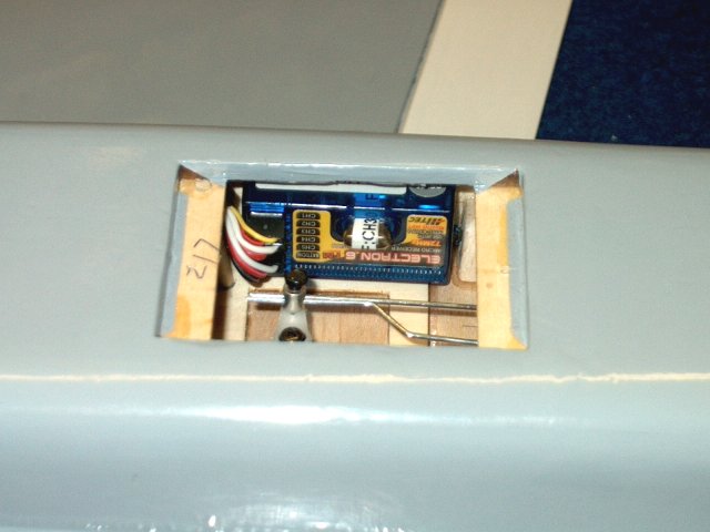
Receiver installation is completed
| |

Install the access cover
| |
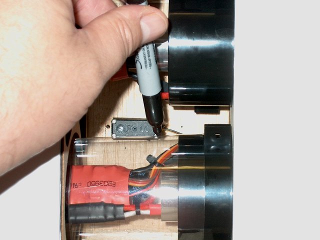
Label your power connectors for each motor
for easy identification | |
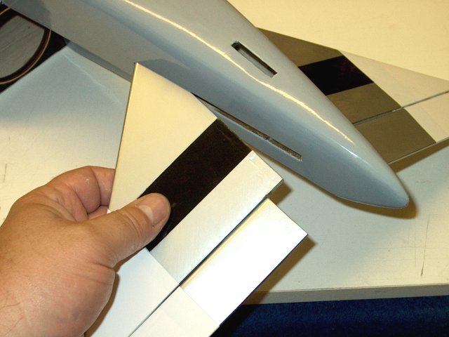
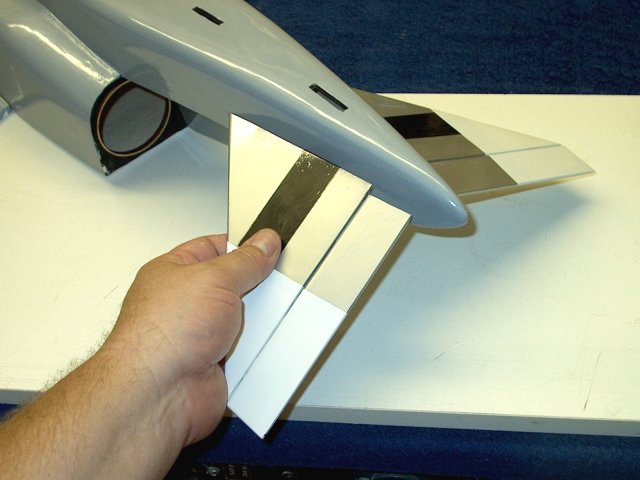
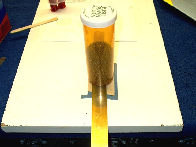
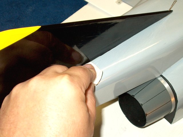
The intake streamers are held in place and
a mark is made on the bottom of each streamer as shown
| |
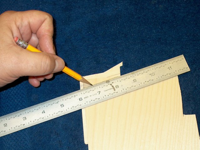
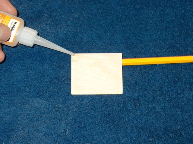
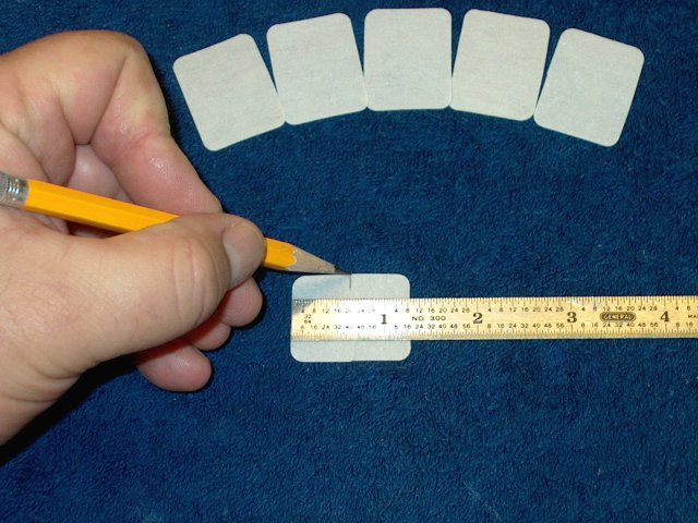
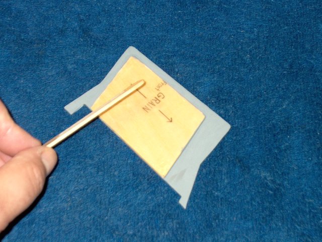
A 1/16" piece of plywood is used to make
some spacer plates | |
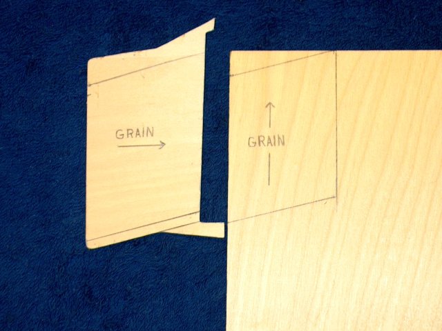
It is important to note the grain
direction. One of the streamers were warped and by using a
cross grain, it will stiffen and straighten them out
| |
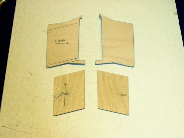
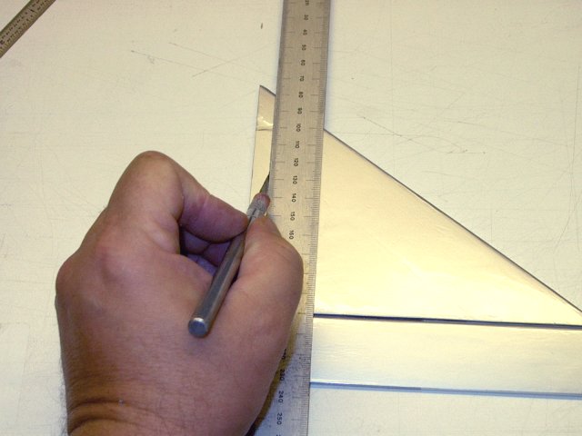
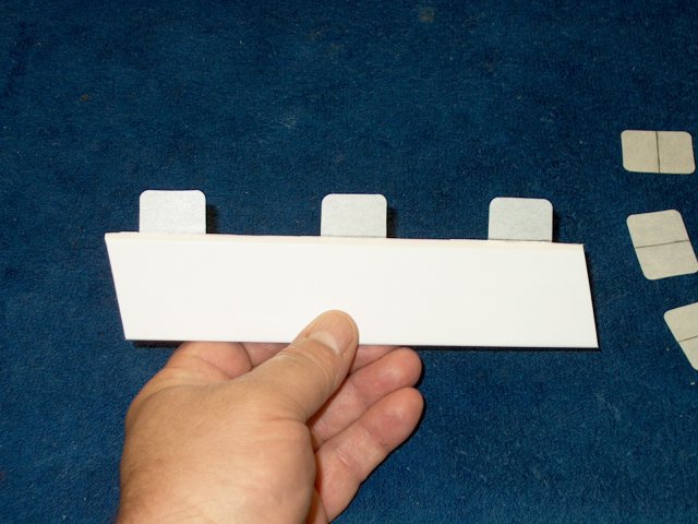
Make two spacer plates as shown. The
spacer plates should be cut 3/16" shorter than the front and
sides of the streamer exposed areas and the rear should sit
flush with the streamer rear | |
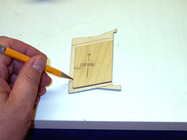
The outline of the spacer is drawn on the
streamer. Note the 3/16" clearance on the front (shown left)
and sides | |
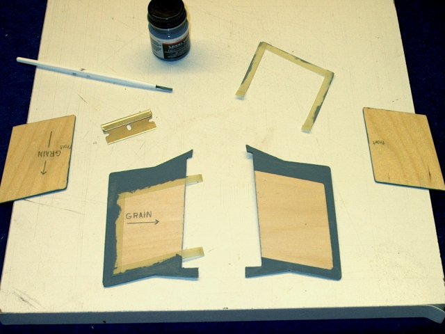
Gray paint is used to color the area of
each streamer plate that will be exposed
| |
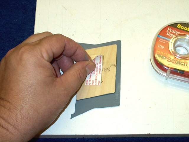
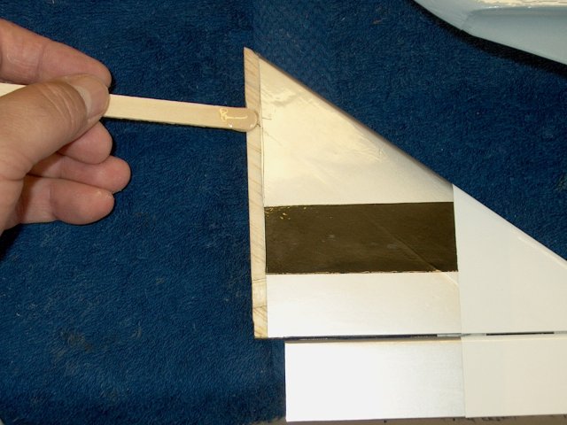
Double sided poster tape is applied to the
spacer. Make sure the spacer plate is in the correct position
as shown | |
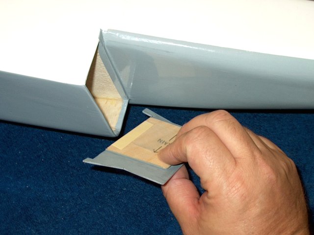
The assembly is held together and
installed in place | |
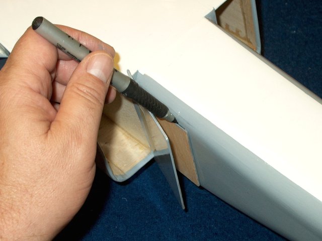
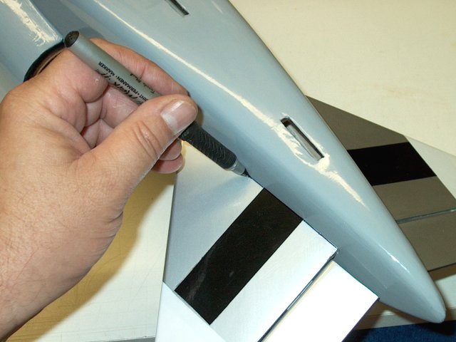
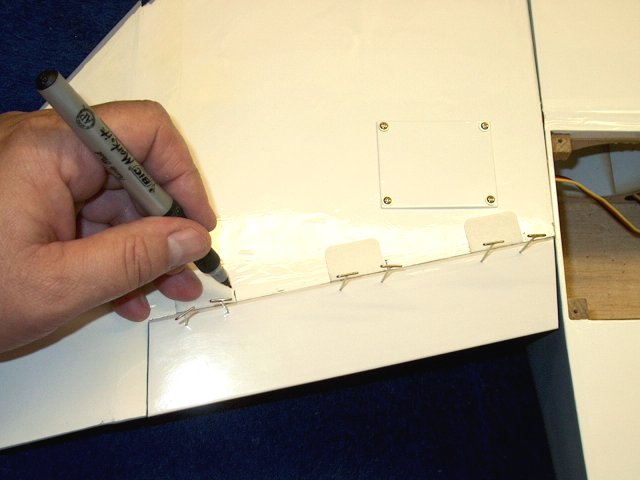
A marker is used to transfer the outline
of the spacer to the side of the fuselage
| |
Cut about 1/16" inside the line that was
drawn. Be careful to only cut the covering and not the
balsa | |
Remove the excess covering
| |
Draw lines can be cleaned with denatured
alcohol and a paper towel | |
A thin coat of epoxy is applied to each of
the streamers and spacer plates. Be careful to make sure you
are applying epoxy to the correct side of the spacer plate,
which is the side that faces the streamer
| |
The spacer plate is positioned correctly
on the streamer. The assembly is weighted down while the epoxy
sets; this will help straighten out any warping
| |
Epoxy is applied to the plate
| |
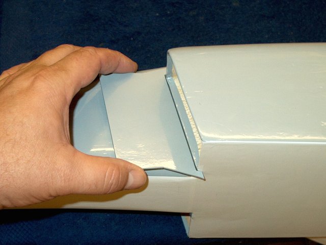
Position the streamer flush sgainst the
intake | |
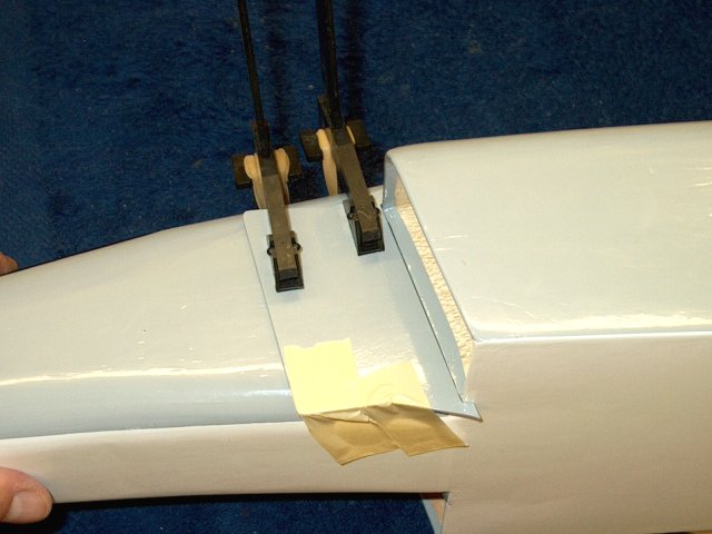
Tape and clamps are used to hold the
streamer in place while the epoxy sets
| |
The other side is completed in the same
manner as the first | |
Streamers shown installed
| |
Use a knife to remove excess covering from
the bottom of the vertical stab | |
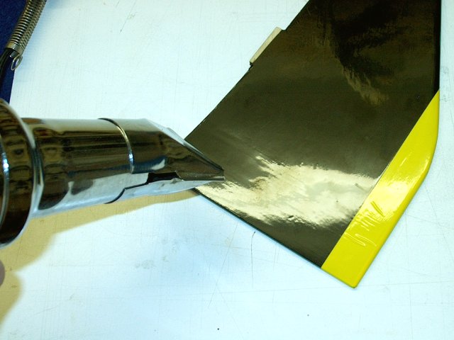
Check your stab on a flat board and make
sure it sits flat. Repair any bowing by bending the piece
straight and shrnking with a heat gun
| |
The bottom of the stab may need to be
sanded for a good fit | |
Check for no gaps at the fuselage
joint | |
Install the stab and trace its shape on
the fuselage with a marker | |
Cut the covering inside the pattern line
for the stab | |
Remove the covering from the
fuselage | |
The marker lines can be cleaned up with
denatured alcohol | |
The stab seams are sealed with an
iron | |
Masking tape is applied to the fuselage to
keep it clean of excess epoxy | |
Masking is also appied to both sides of
the stab and it is ready for epoxy | |
15 minute epoxy was used and applied to
the bottom of the vertical stab | |
Epoxy is also applied to the
fuselage | |
Install the stab in place
| |
Excess epoxy is cleaned with
alcohol | |
Use a square to check stab
alignment | |
Remove the tape and clean up any
additional epoxy before it sets | |
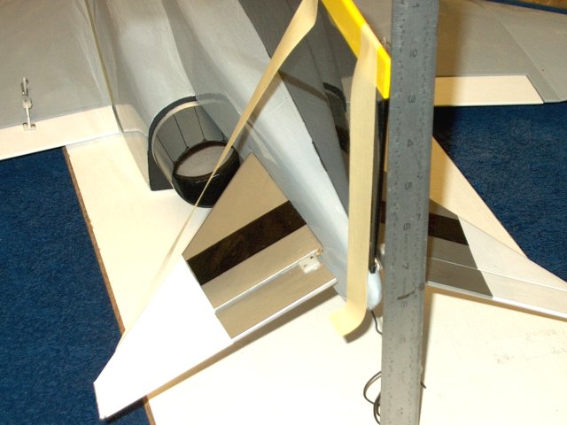
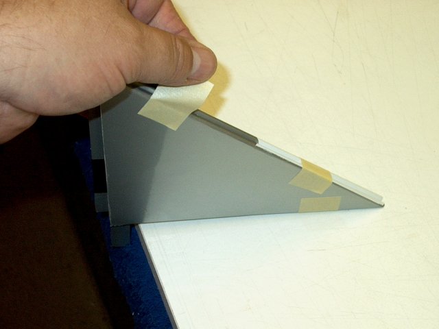
Masking can be used to hold the vertical
stab perpendicular to the surface | |
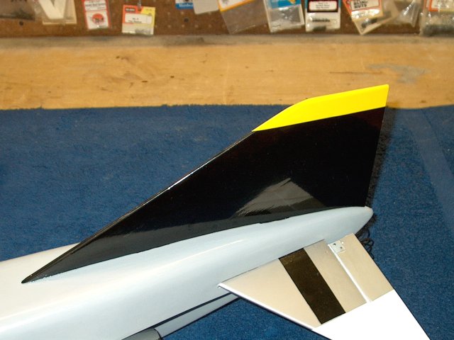
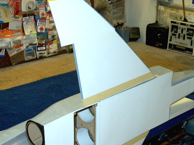
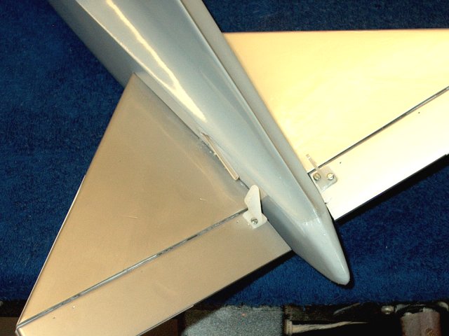
Vertical stab installation shown
completed | |
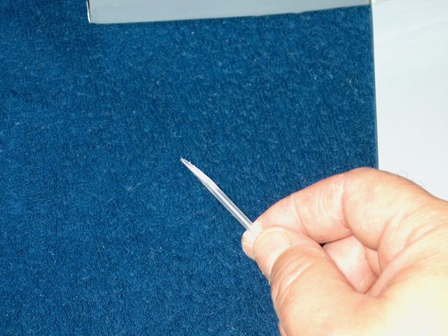
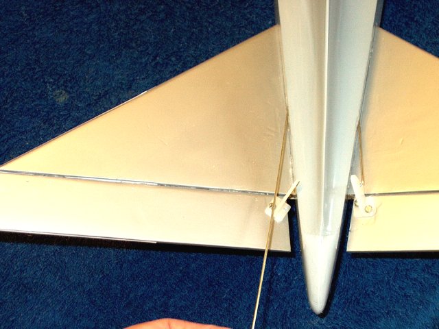
A T-Pin is pushed through the pin hole in
the towhook hardwood block to locate the hole under the
covering on the outside | |
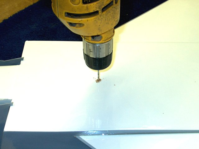
The hole is drilled with a 5/64"
bit | |
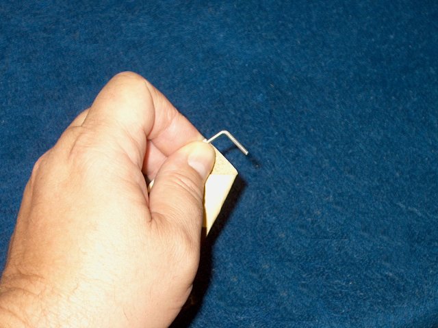
Rough up the side of the towhook that will
be glued. Slightly bend the hook to an outward angle so the
towline will easily drop off | |
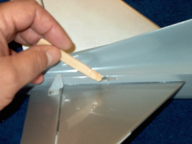
A toothpick is used to apply epoxy to the
hole and hook | |
The towhook is installed in the fuselage.
Do not install it too deep; the top of the towhook should just
exit the hardwood block inside | |
Towhook shown installed. Insure it is
pointing straight back | |
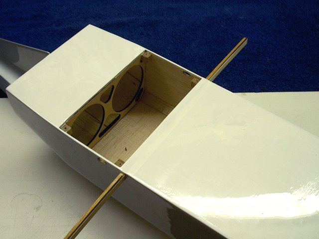
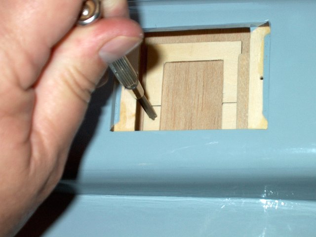
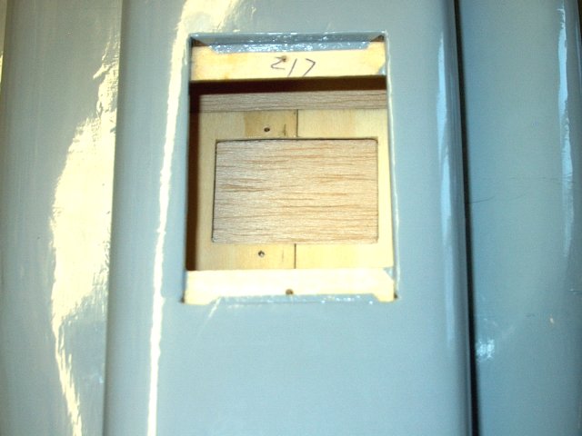
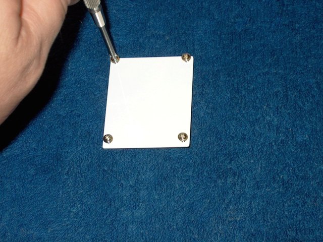
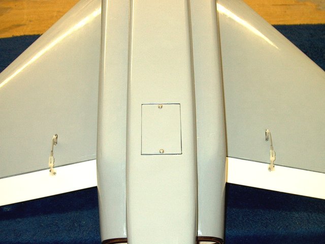
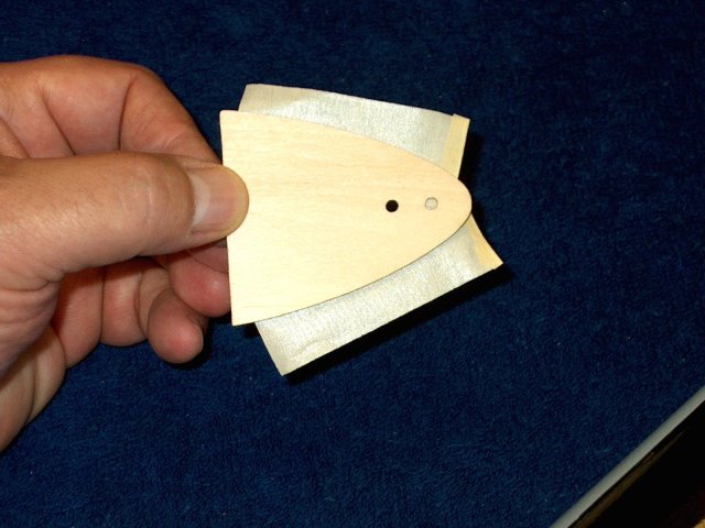
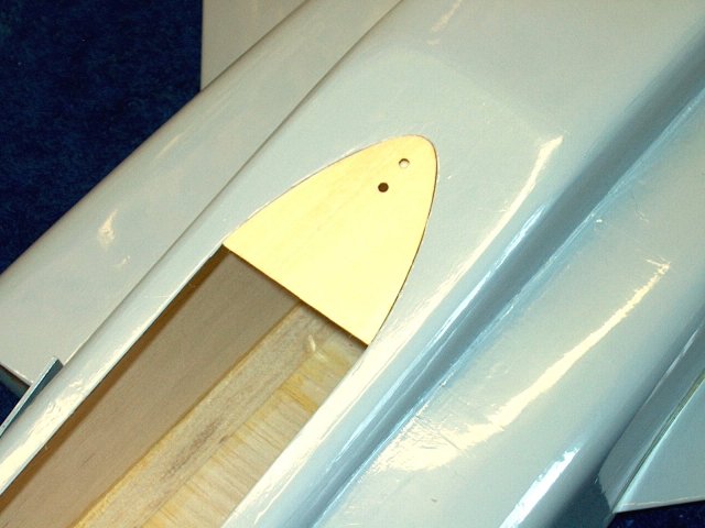
Appy epoxy to one side of the small piece
of plywood for the cockpit | |
This plate is installed as shown, with it
centered and the rear flush to the opening in the frame
| |
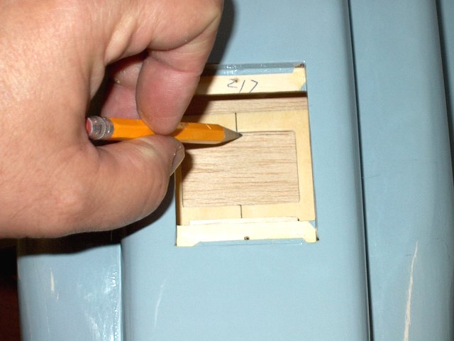
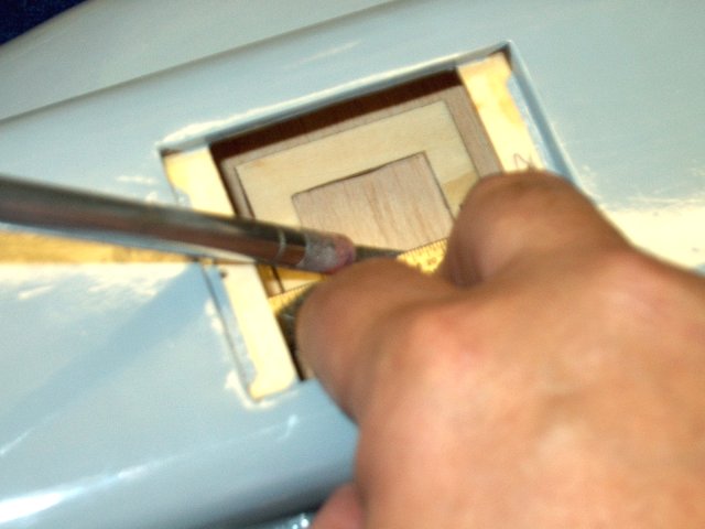
A second piece shown on the left was cut
from 1/16" ply as wide as the first piece and 1 1/4" long.
Epoxy is applied to the first piece for fastening
| |
The second ply plate is installed flush at
the opening and even with the sides so it can hook under the
front of the fuselage cockpit area | |
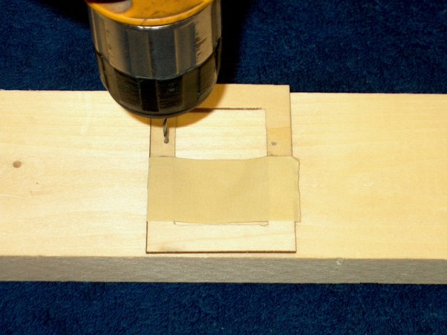
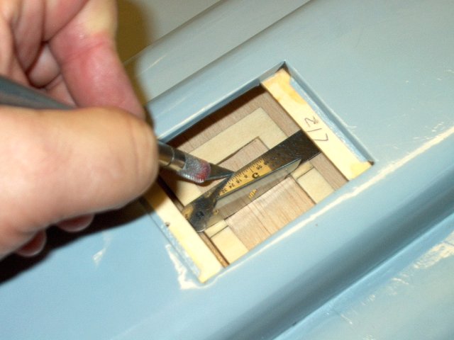
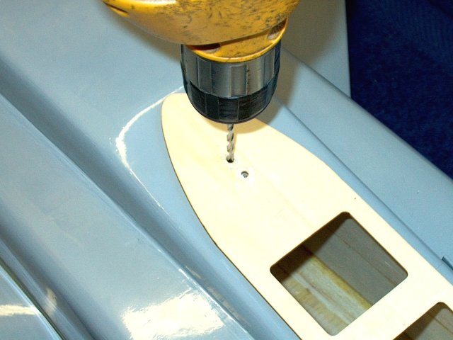
Center the shelf with the front of the
fuselage, then mark and drill a 1/8" hole in the center of the
plate as shown | |
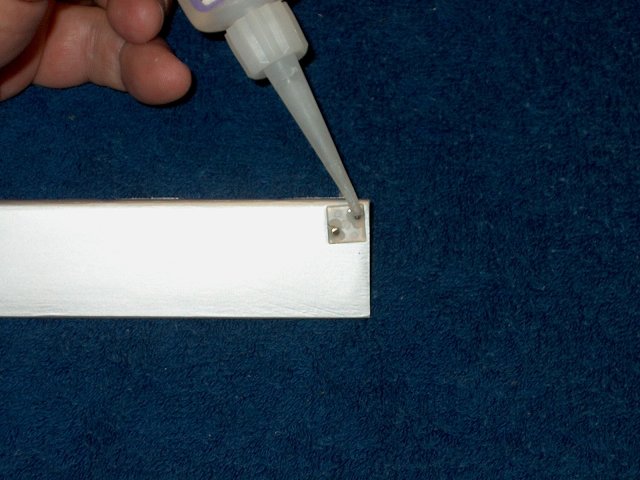
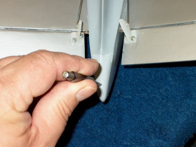
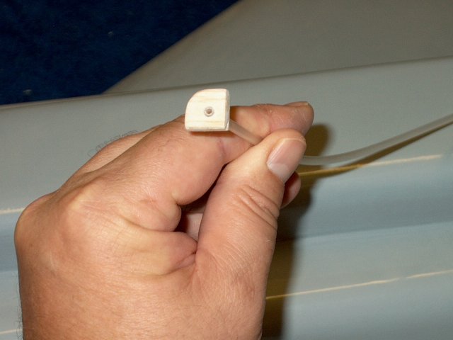
Apply epoxy to a 1/8" wooden dowel and
insert it into the hole so it slightly protrudes out the
bottom of the fuselage | |
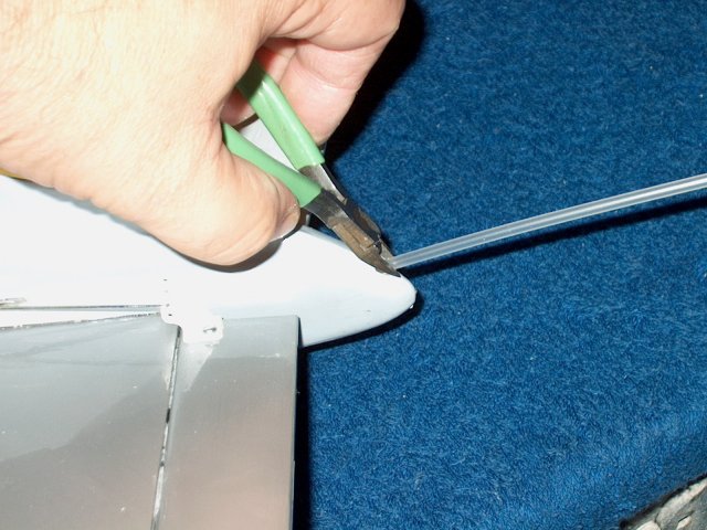
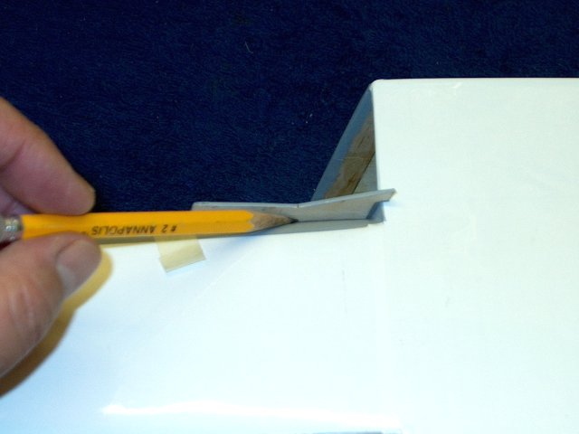
Once the epoxy sets, space the dowel with
a ruler and cut it flush as shown | |
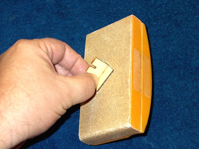
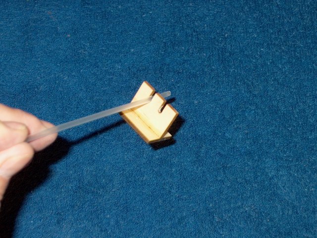
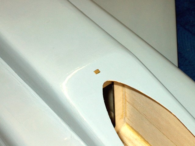
Open up the hole in the shelf so it is a
slot and fit it to the dowel. This will keep the front of the
cockpit centered when installed | |
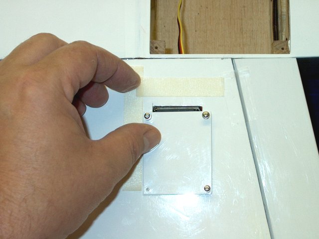
Tape is applied to the short cockpit
piece | |
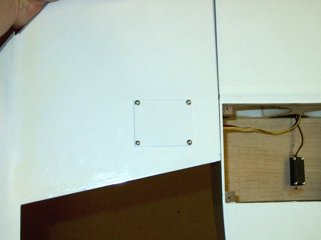
This plate is secured in place as
shown | |
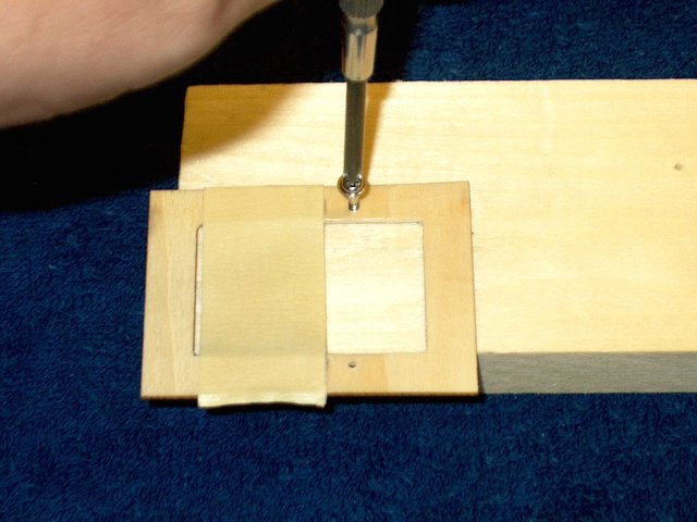
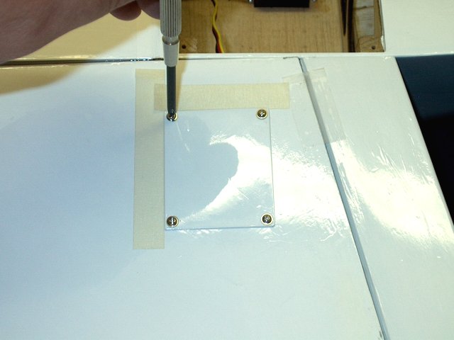
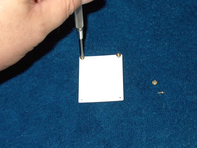
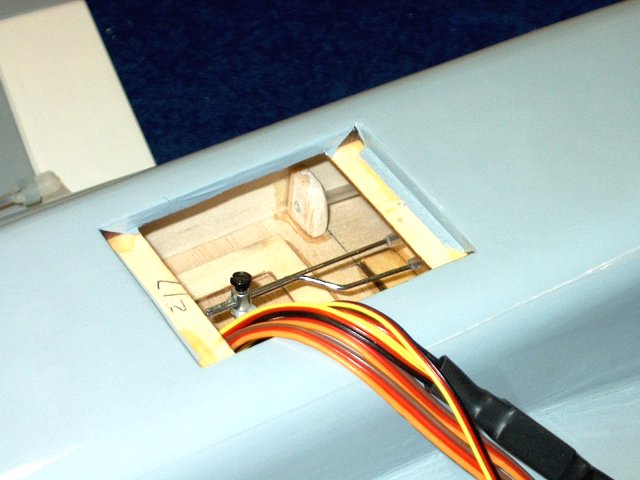
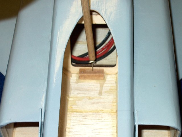
Install the cockpit ply shelf in place and
make sure it is centered in the front and rear, then hold both
rear pieces together with one hand and drill through both
holes with a 1/8" bit | |
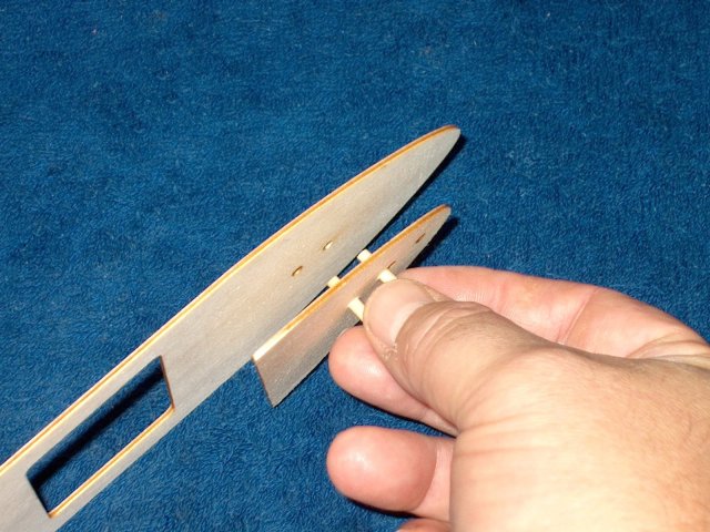
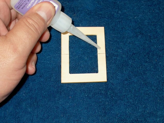
Two 1/8" wood dowels are cut about 3/4"
long and inserted in the small plate. Apply epoxy to the small
plate and use the dowels as guides to connect it to the
cockpit shelf | |
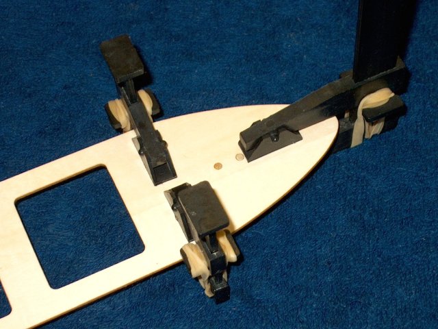
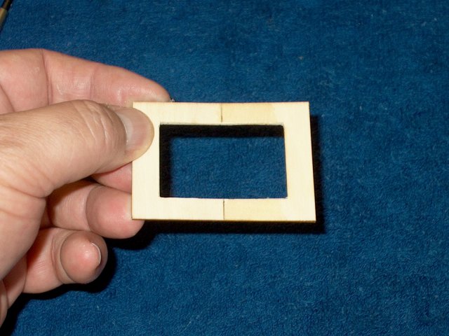
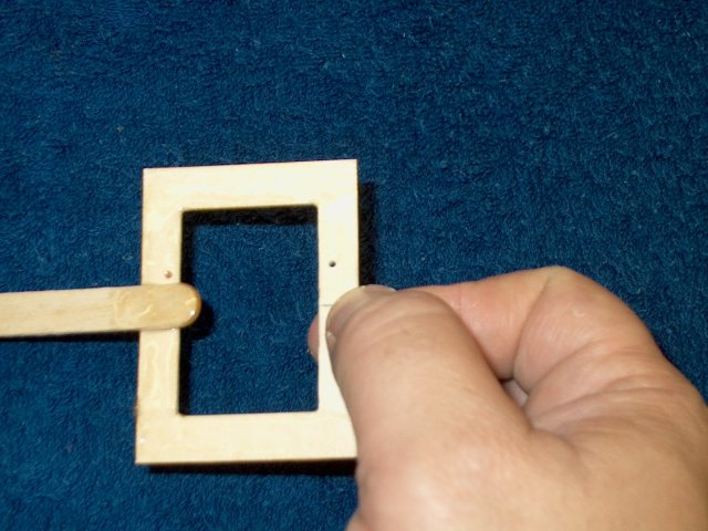
The two pieces are clamped together until
the glue sets, then the dowels are cut and sanded flush on
both sides | |
The shelf is hooked in the front and
should drop in place at the rear. Draw a center line at the
rear of the shelf | |
Make a mark with a punch about 3/8" from
the end | |
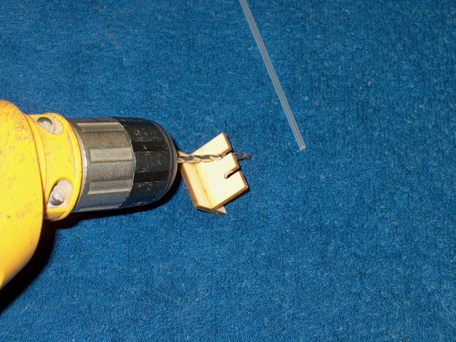
Use a 3/16" drill and make a hole through
both pieces | |
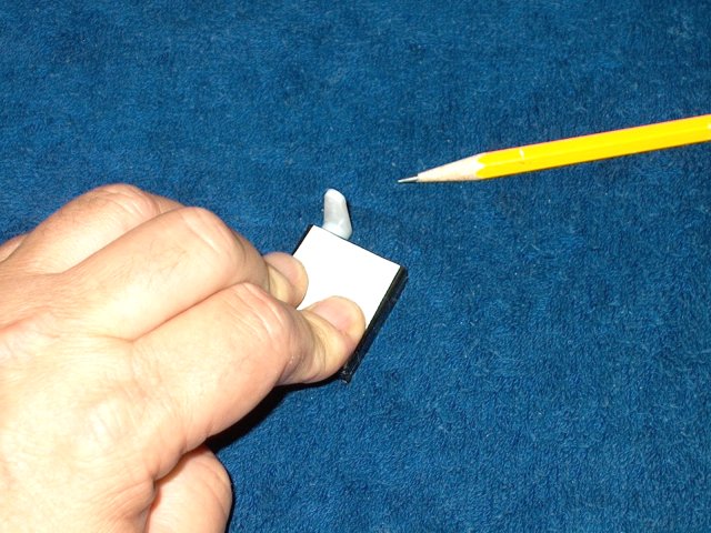
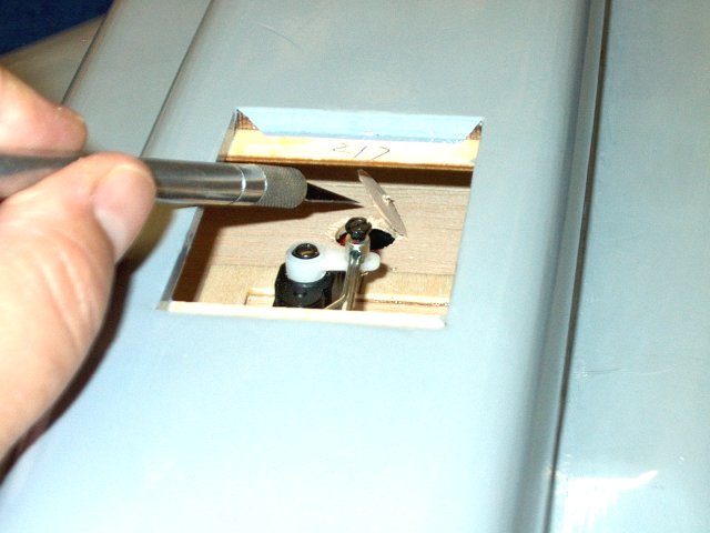
Remove the shelf and cut the hole to a
rectangle so the magnet is a nice and tight fit
| |
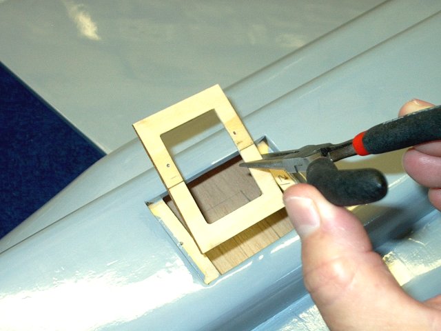
Install the shelf, make sure the front of
it is centered and transfer the rectangle shape to the
fuselage opening | |
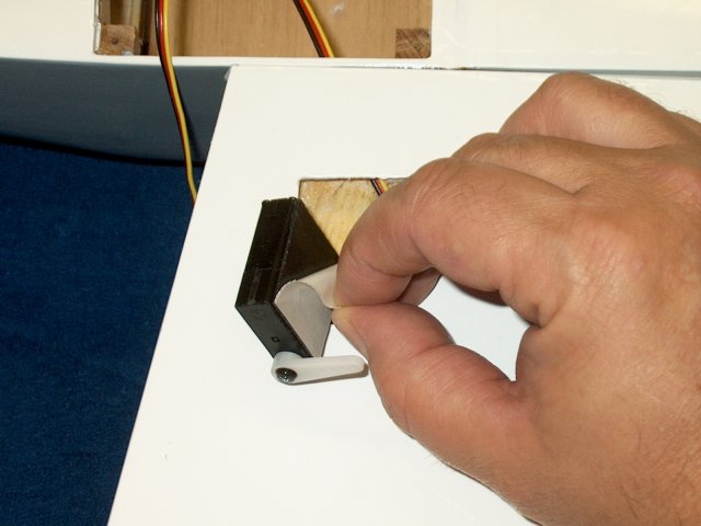
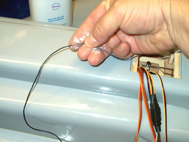
A piece of masking tape is applied to the
bottom of the shelf, then epoxy is applied to the edges with a
toothpick. Install the magnet flush to the tape and apply
epoxy to the top to fill the hole. The toothpick can be used
to insure the magnet is pushed down and seated flush with the
tape | |
once the epoxy sets, remove the tape and
clean the bottom exposed surface of the magnet
| |
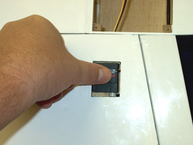
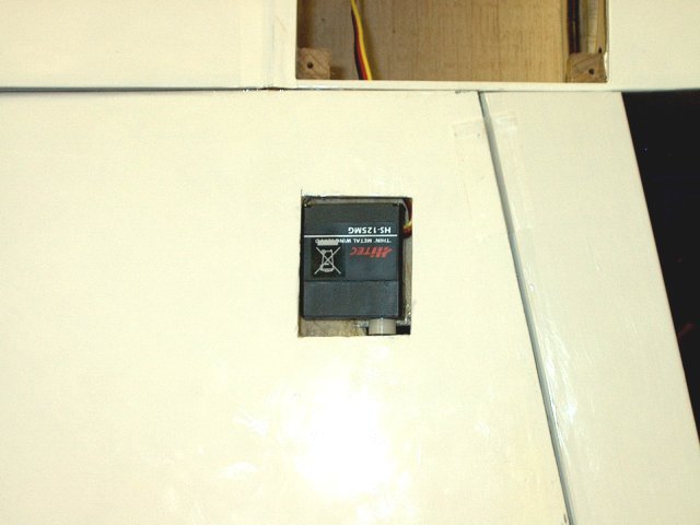
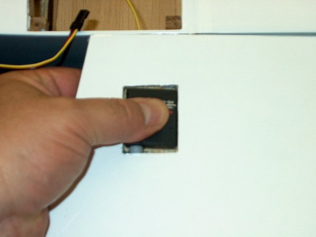
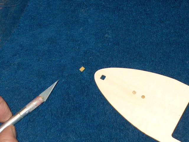
Cut a 1/2" square piece of ply, then apply
epoxy to the ply square and hole in the fuselage. Masking can
be used to hold the ply square in place underneath the hole
inside as shown. Check the magnet direction with the one on
the shelf, then install it in the opening in the correct
direction. The shelf is used to make sure the magnet is flush
to the top of the fuselage | |
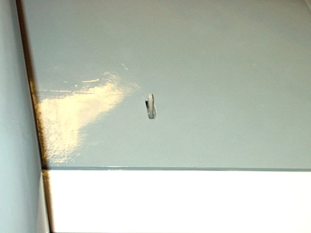
The magnet is now installed flush with the
top of the fuselage. Clean up any excess epoxy with
alcohol | |
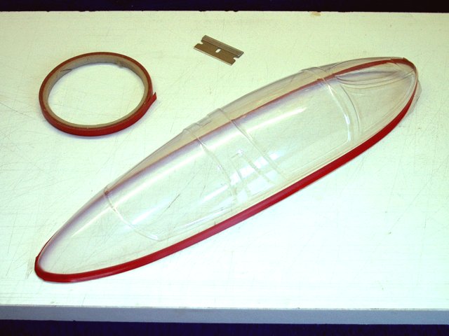
Tape is a nice tool to use when marking an
outline of the canopy shape for cutting
| |
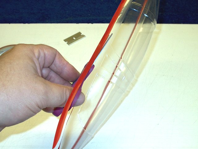
Cut out the canopy as shown, leaving a
little extra for fitting. Sand the edges and deburr them until
the canopy fits well | |
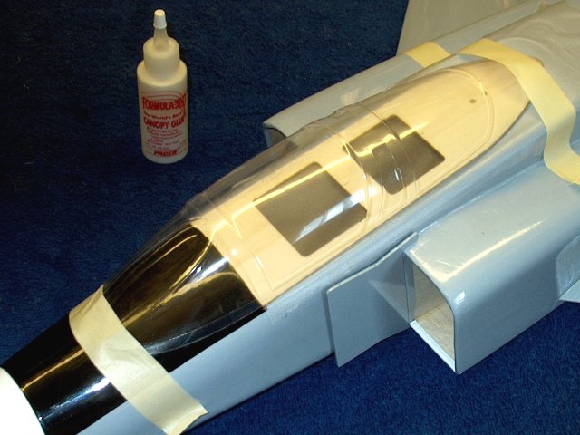
Install a piece of plastic wrap in the
fuselage area and cut a slot in the plastic for the front hook
so it can engage. Detail the cockpit if you wish before
fastening the canopy. Use canopy glue or clear silicon to
attach the canopy to the cockpit. Masking can be used to hold
the canopy sides to the cockpit. This completes the cockpit
installation | |
Set the Elevator throws for 10mm up and
down | |
Set the Aileron throws for 10mm up and
5mm-10mm down | |
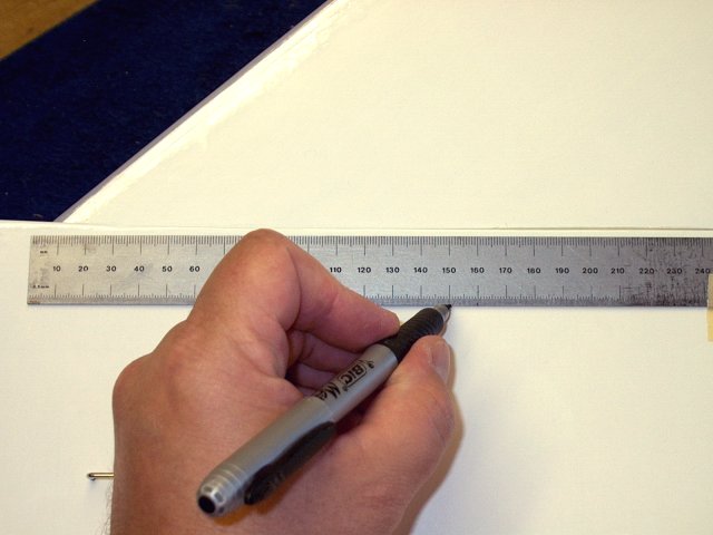
Make balance marks for CG on the fuselage.
CG is at 150mm from the front leading edge if the wing
| |
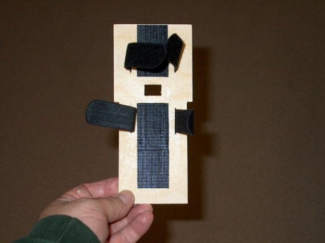
Make a tray for your battery packs. A thin
ply plate and velcro works well. Position the plate in the
fuselage for good balance with the batteries in place and glue
the tray in the fuselage | |
This completes the basic build of the
HET-RC F-4 Phantom | |
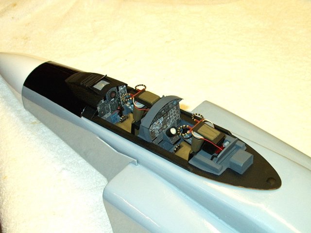
A Detailed Cockpit was built as shown. It
can add some realism to the model | |
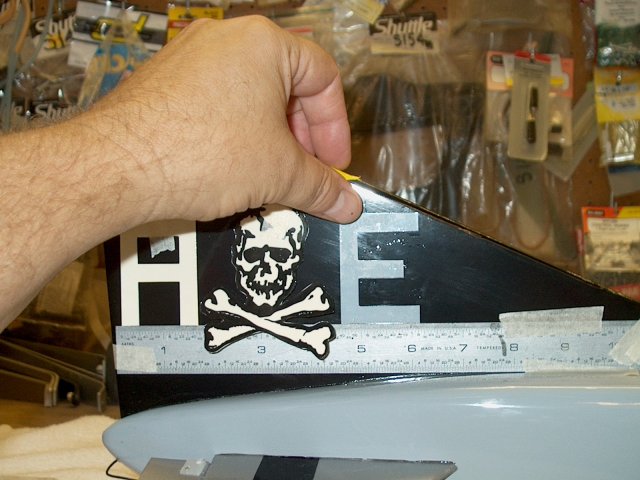
Rulers are used to keep decals aligned
during application | |
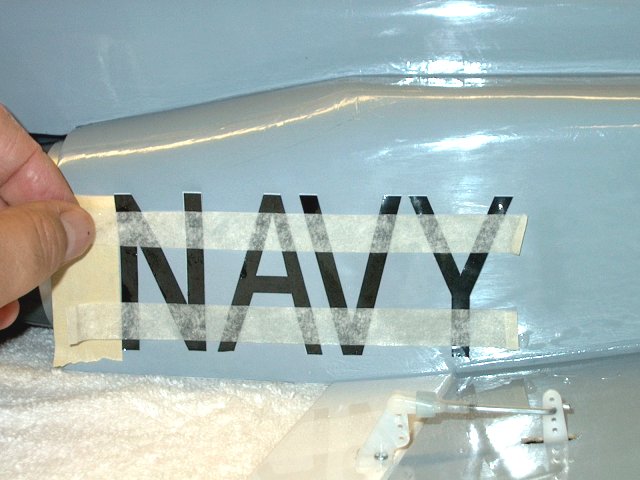
Some decals are cut letter by letter for
realism, using masking tape to keep them spaced
correctly | |
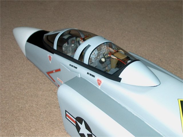
Finished front end decals are shown
| |
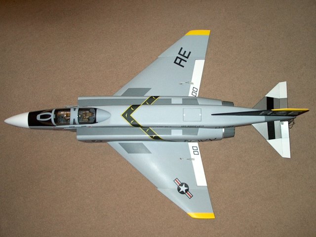
Top View. The F-4 in the pics was
recovered in Dove Gray Monokote | |
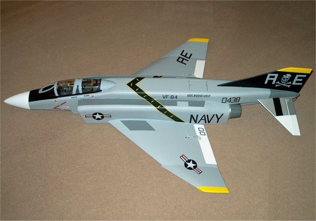
Side View. Once all decals are applied,
Testors Clear Dullcoat paint was used to flat out the Monokote
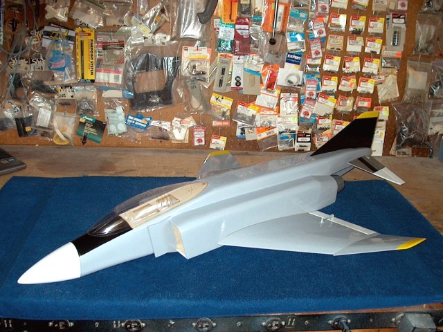
for a more realistic military look | |
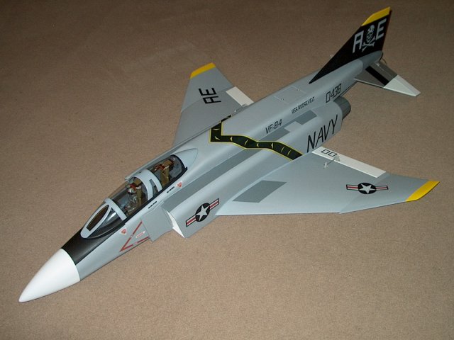
The HET-RC F-4 Phantom Twin Minifan EDF
Jet
| |

This Website and all documents herin are Copyright © 2012 www.scalerocketry.com -
All rights reserved.
| |