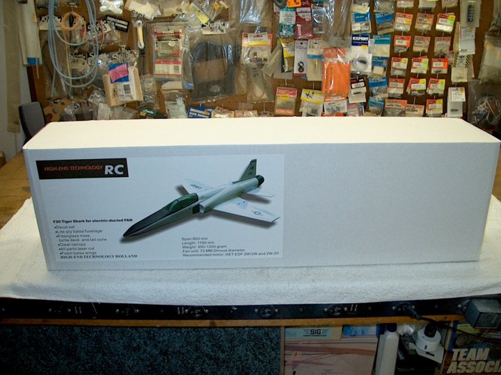
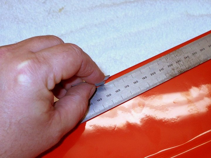
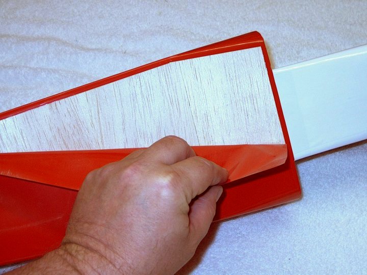
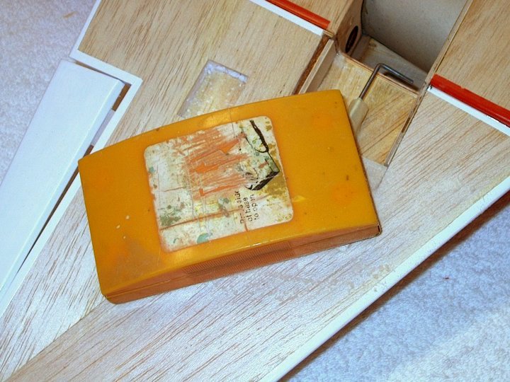
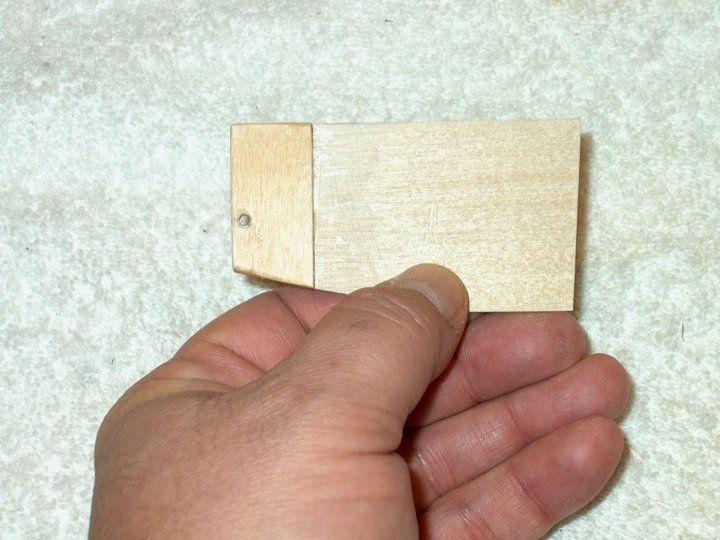
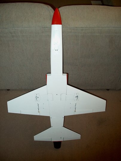
1 - The F-20 as it comes in the
box. |
|
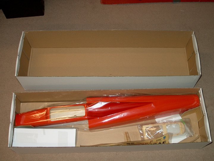
2 - Parts loosely assembled. This model
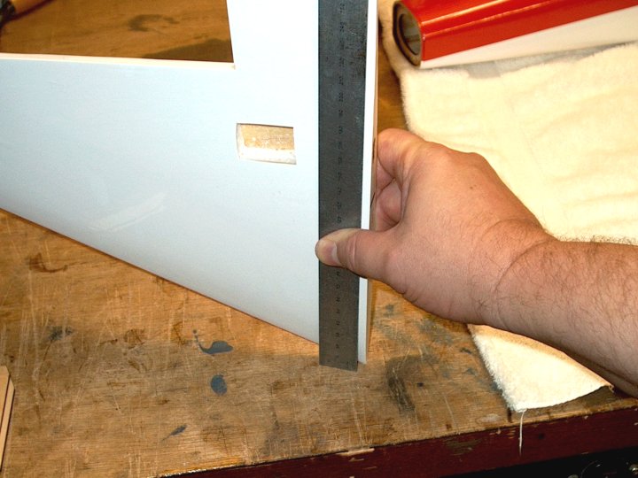
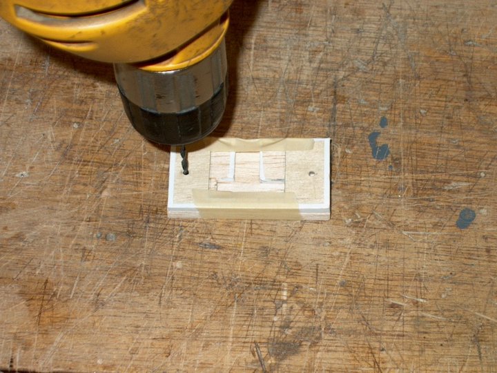
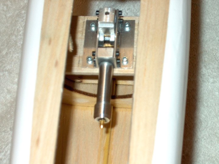
will be retrofitted with Air Retracts.
| |
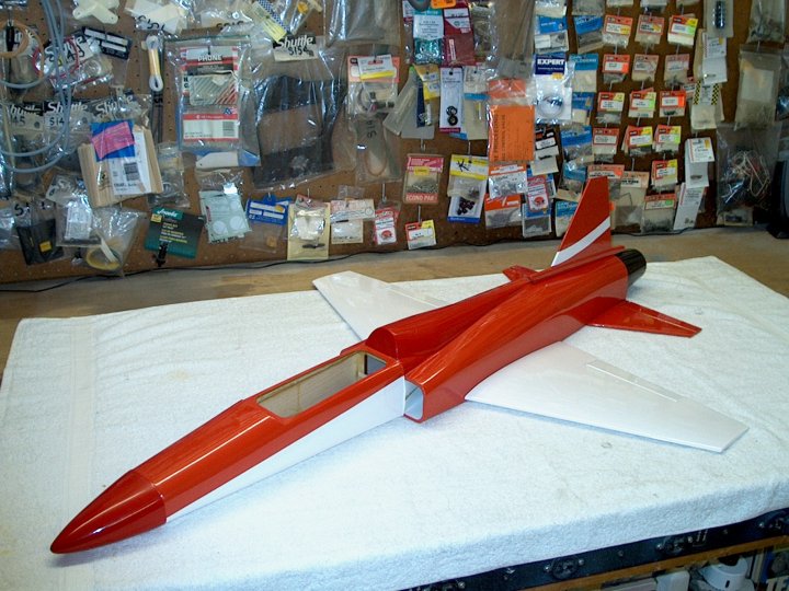
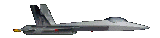
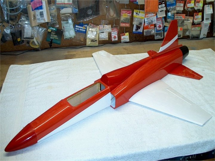
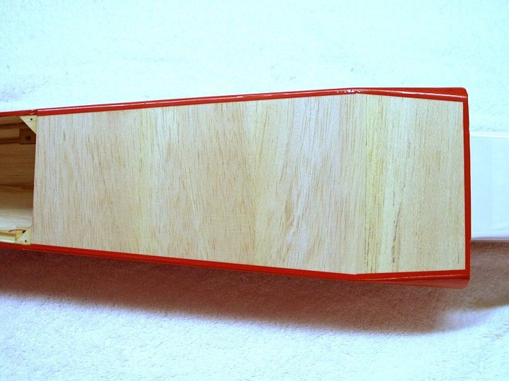
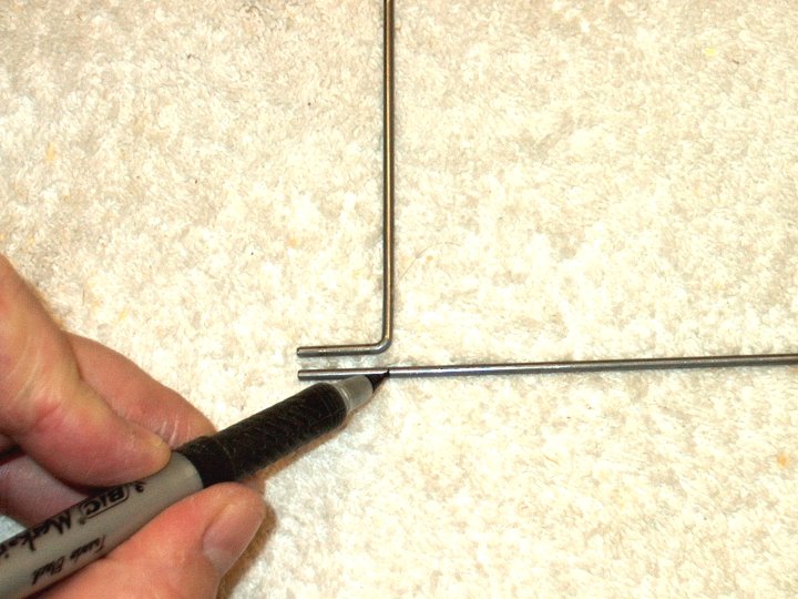
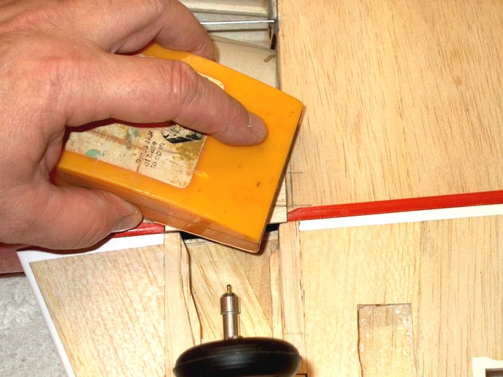
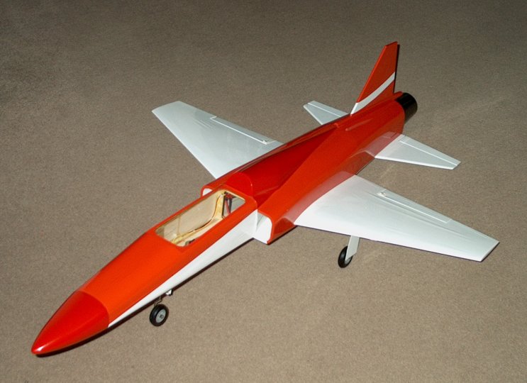
3 - Larger picture of the F-20
Tigershark. | |
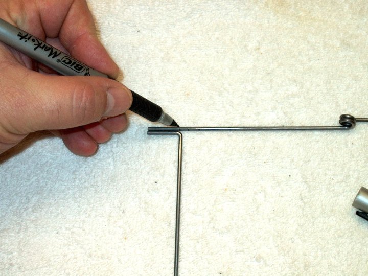
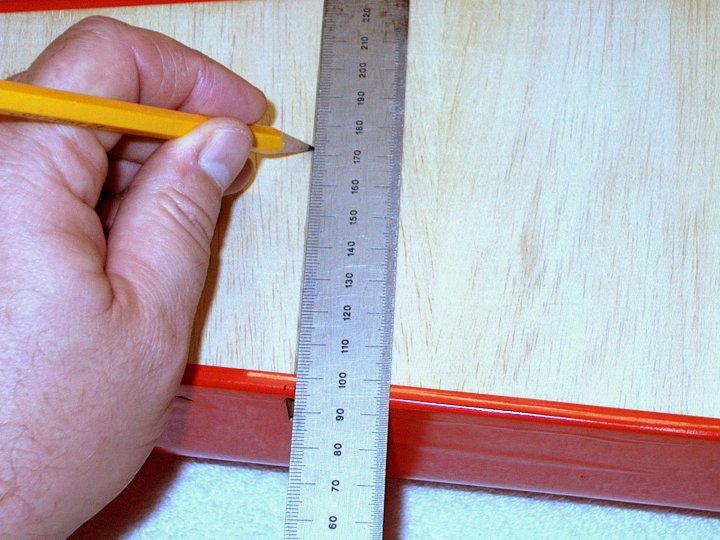
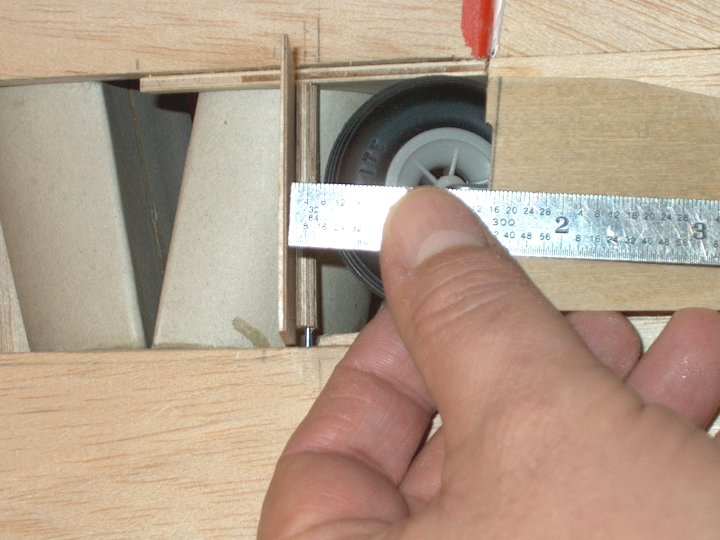
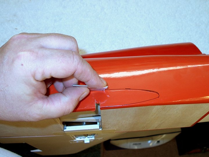
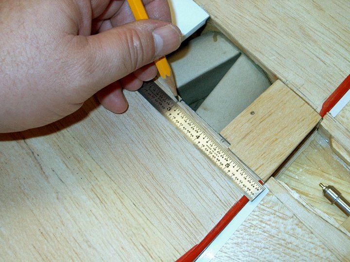
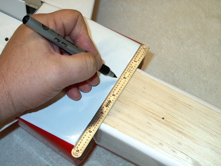
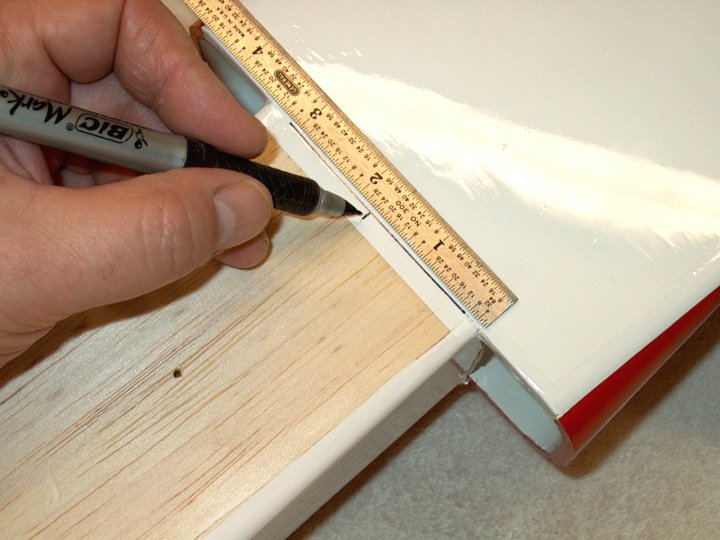
4 - We begin by measuring CG at 67mm from
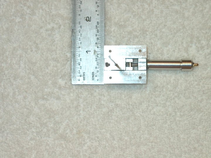
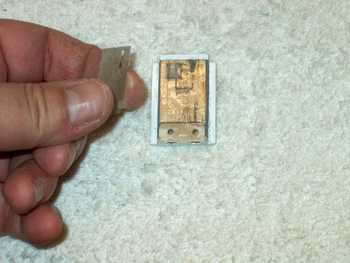
the leading edge. The leading edge root of the wing is placed
perpendicular to the table along with a ruler used to find
CG. | |
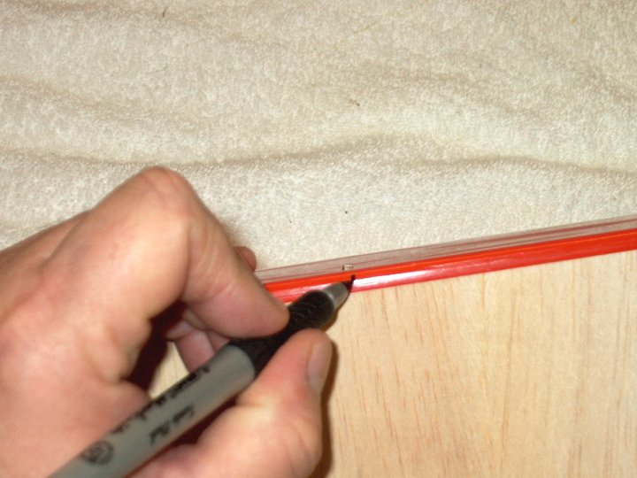
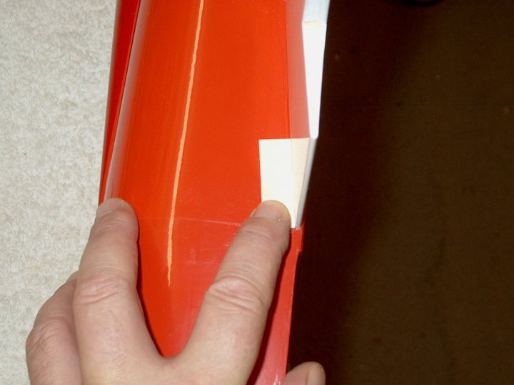
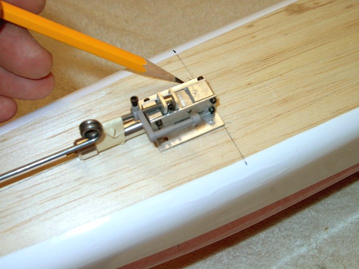
5 - A mark is made at 67mm for CG.
| |
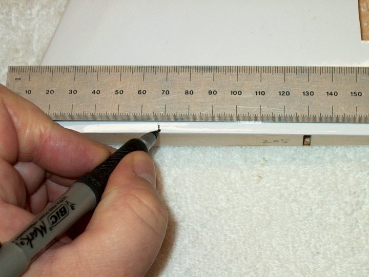
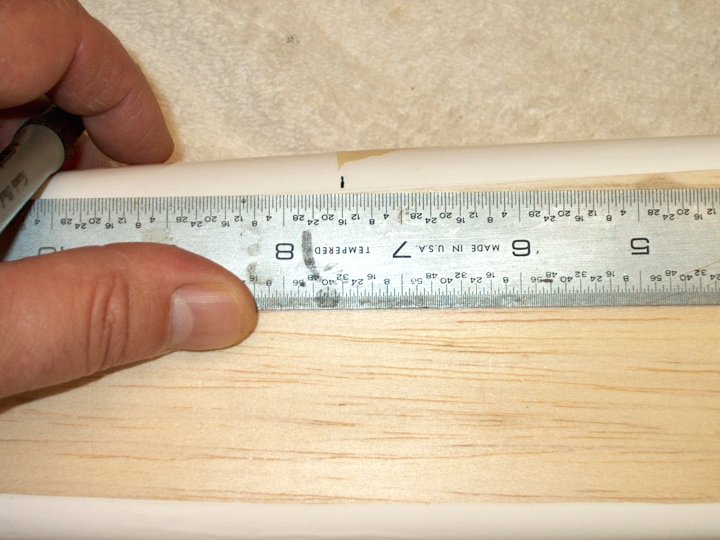
6 - With the ruler anchored to the CG mark
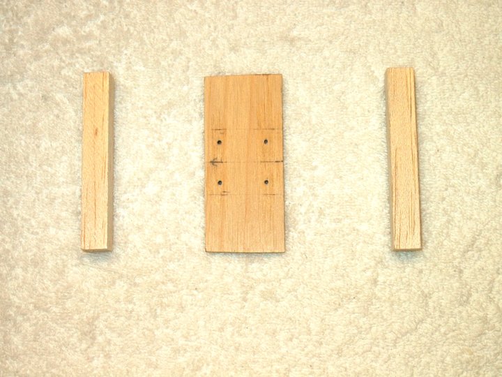
at the bottom, a smaller ruler is used to keep the large ruler
even with the Aileron root on the right. The Aileron root is
perpendicular to the fuselage, so it makes a good measurement
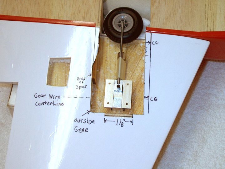
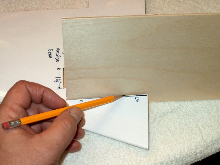
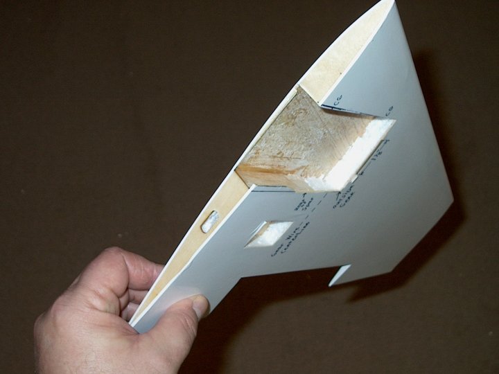
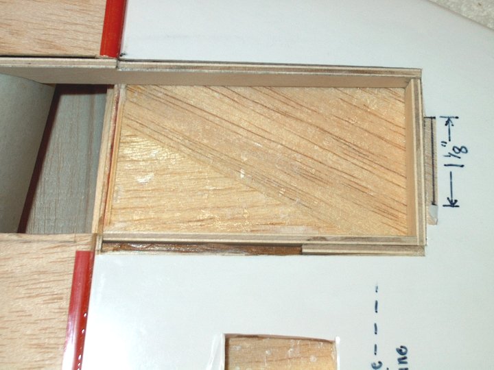
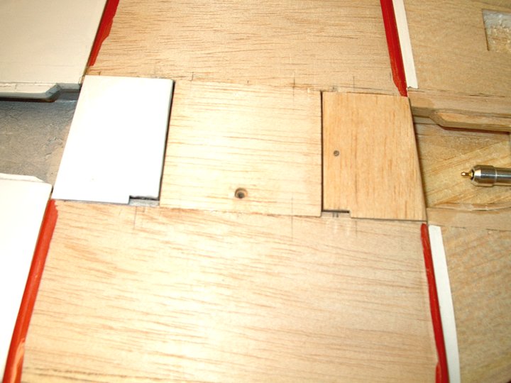
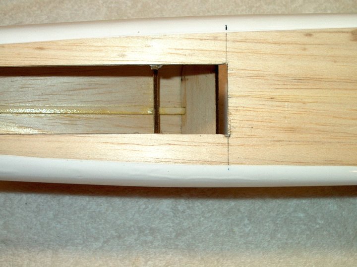
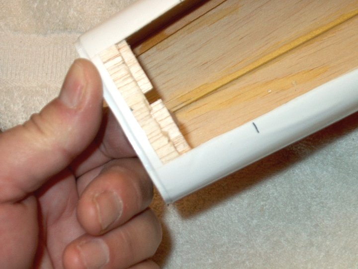
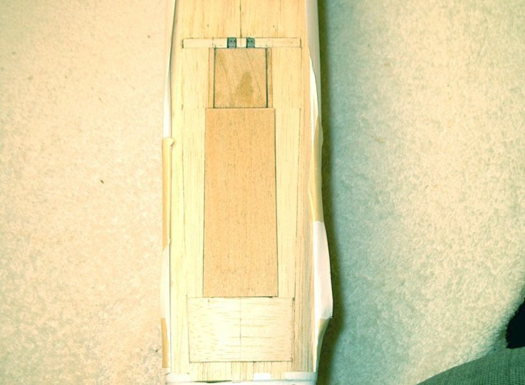
reference point. | |
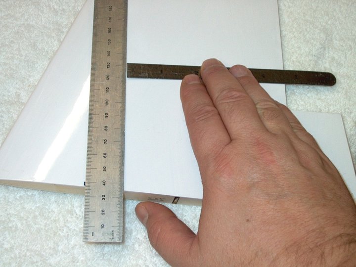
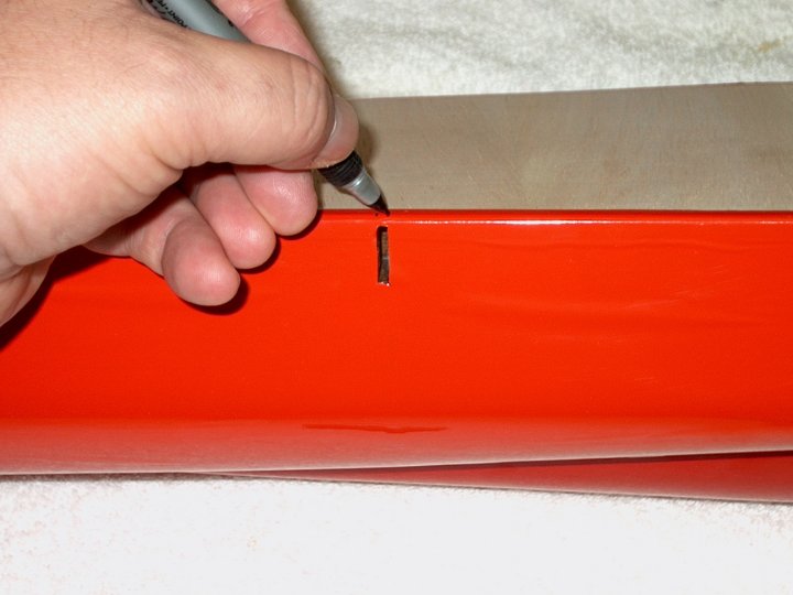
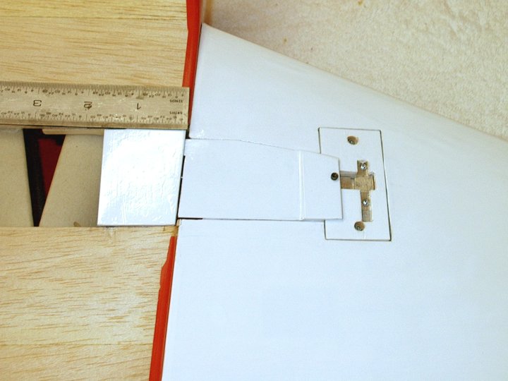
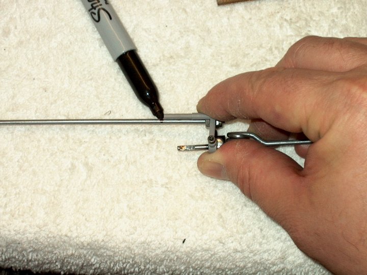
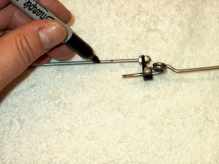
7 - The top and bottom of the ruler is
made even using the Aileron edge. | |
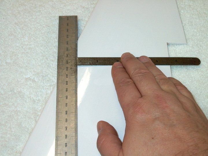
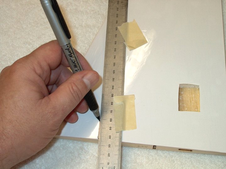
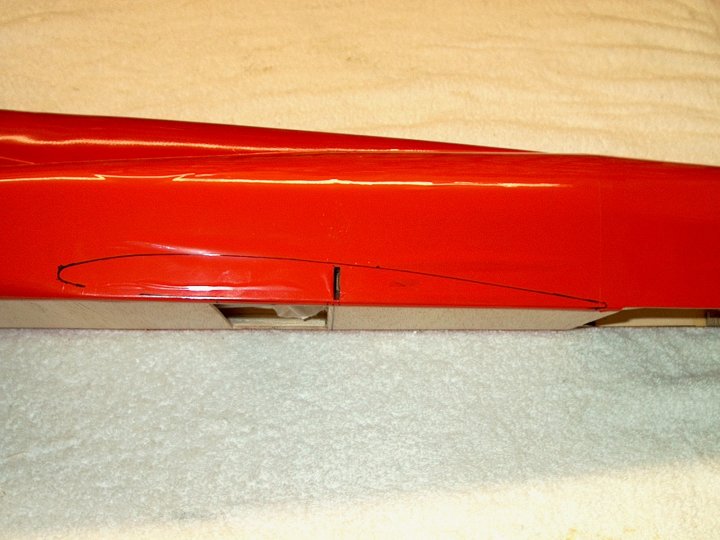
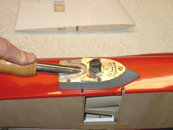
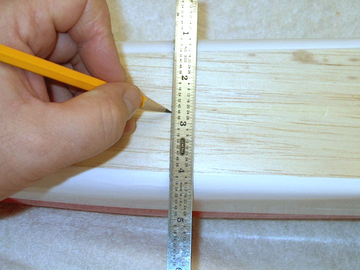
8 - The Ruler is taped in place and a line
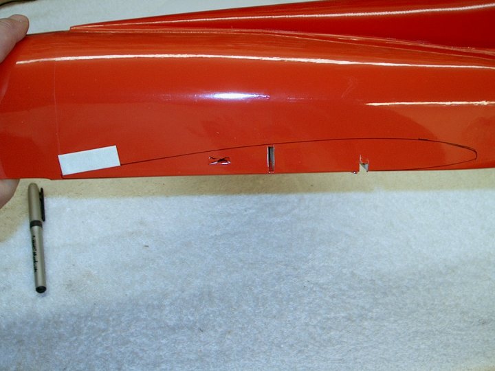
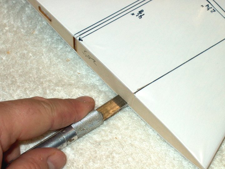
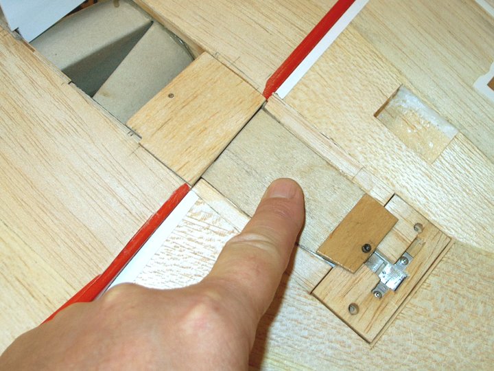
for CG is drawn. | |
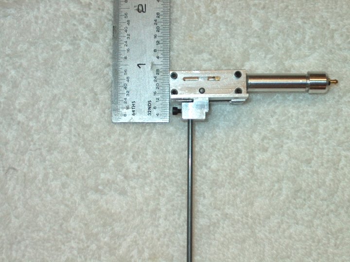
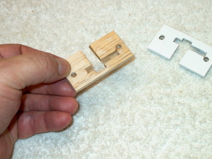
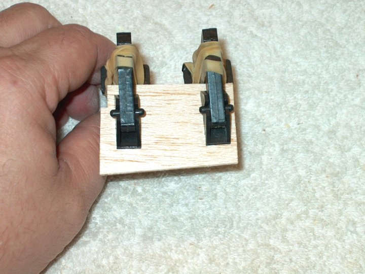
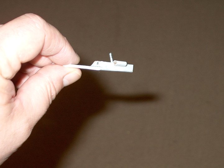
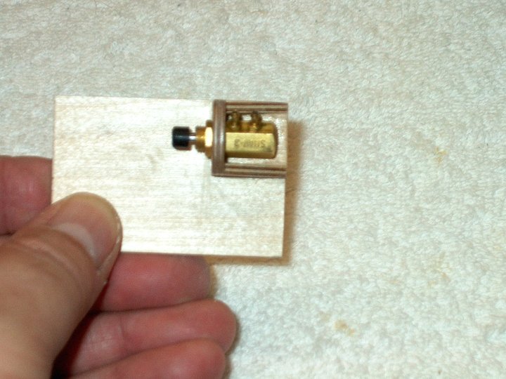
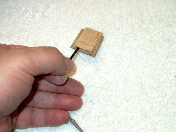
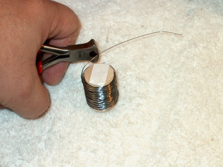
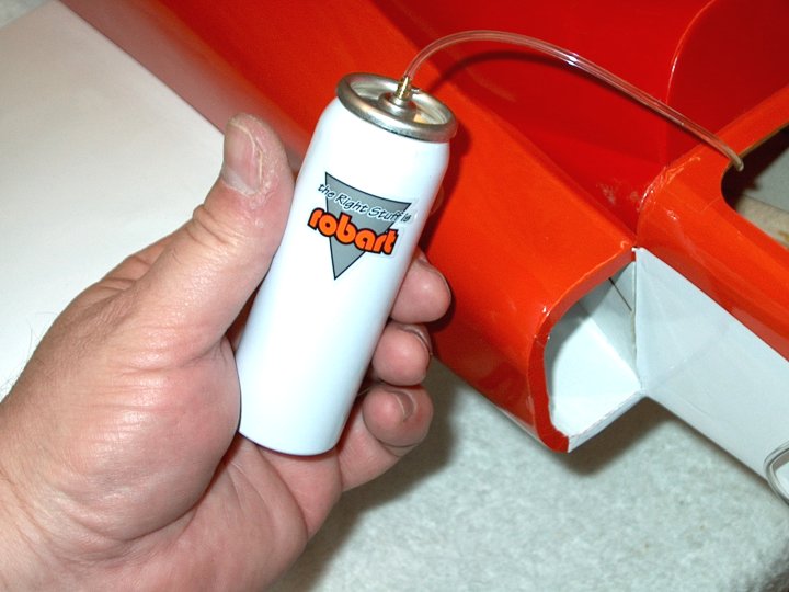
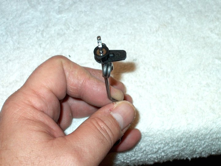
9 - Southeast Model Products small Air
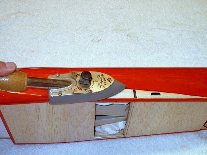
Retracts that will be used. | |
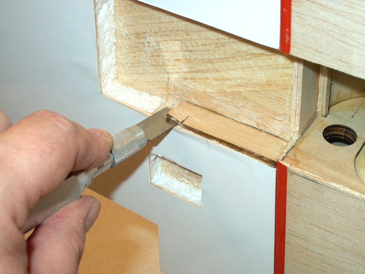
10 - Top view dimension.
| |
11 - Height dimension.
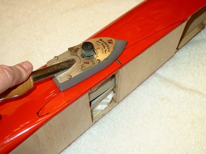
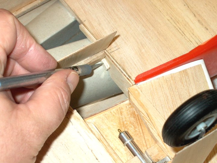
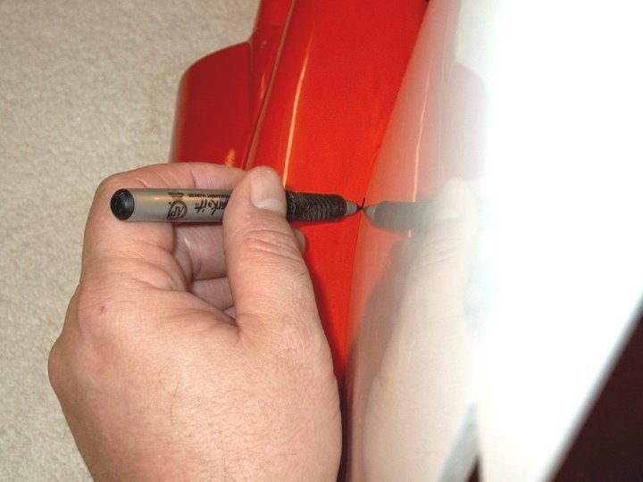
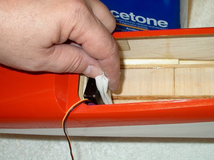
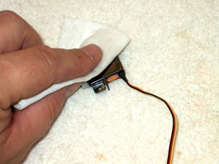
| |
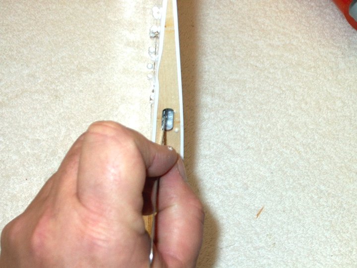
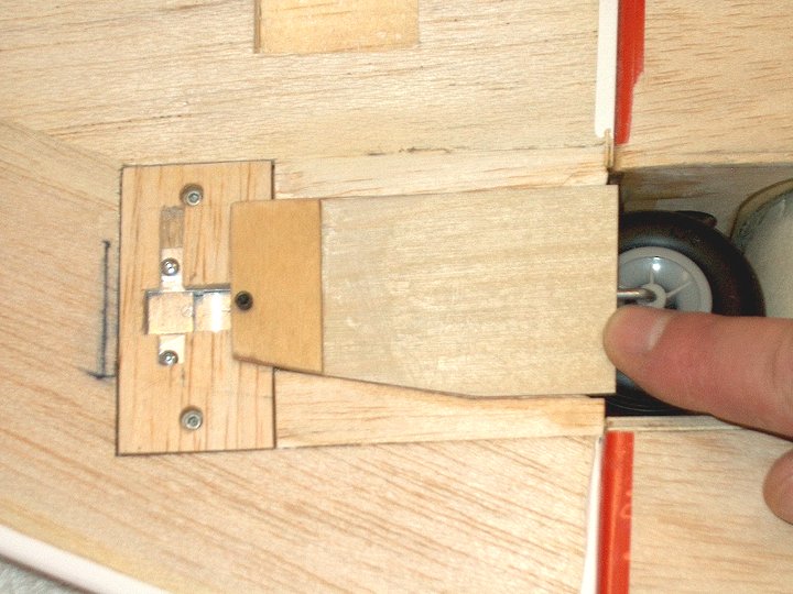
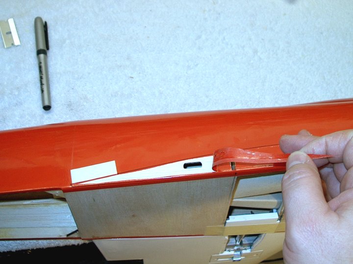
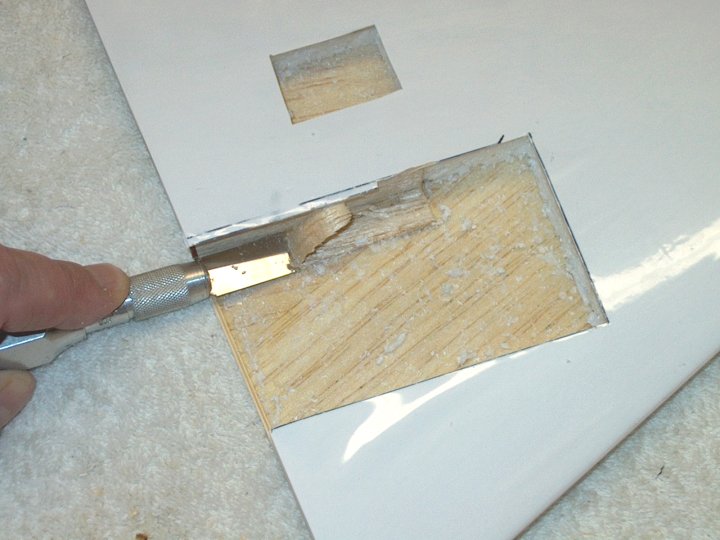
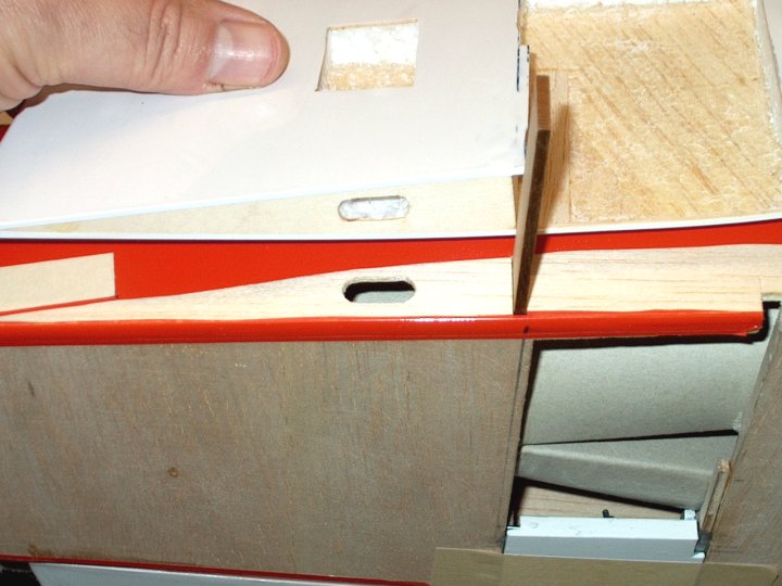
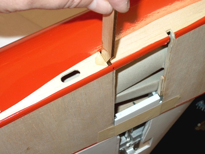
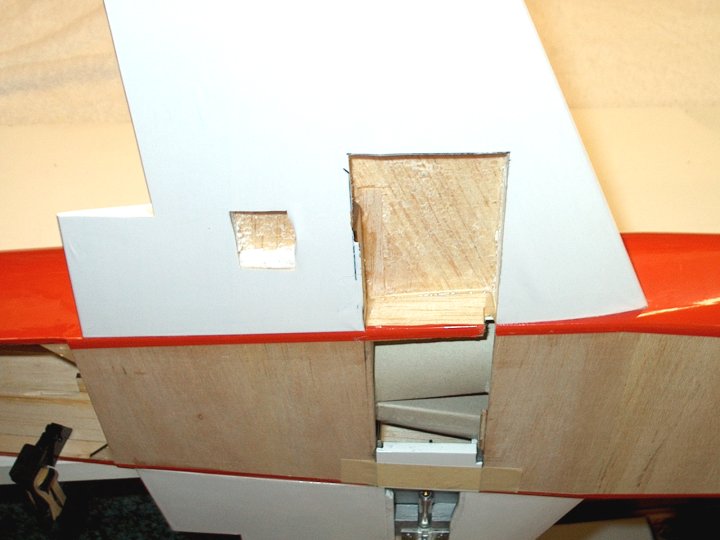
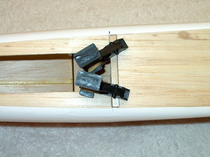
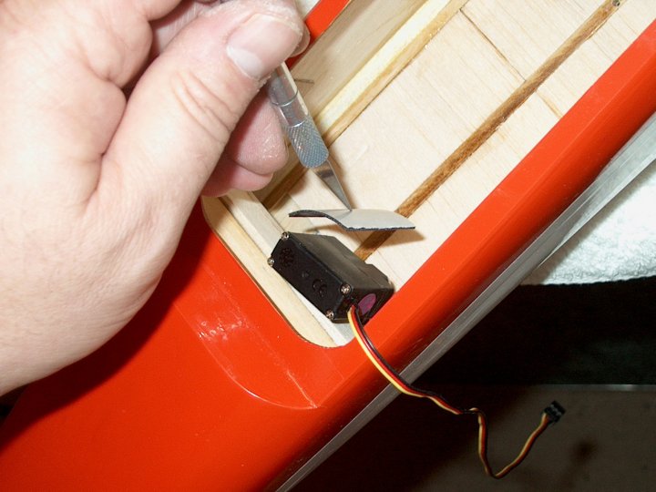
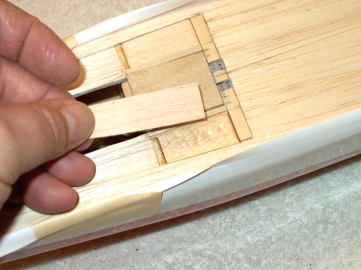
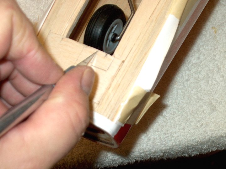
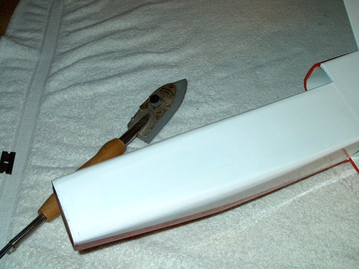
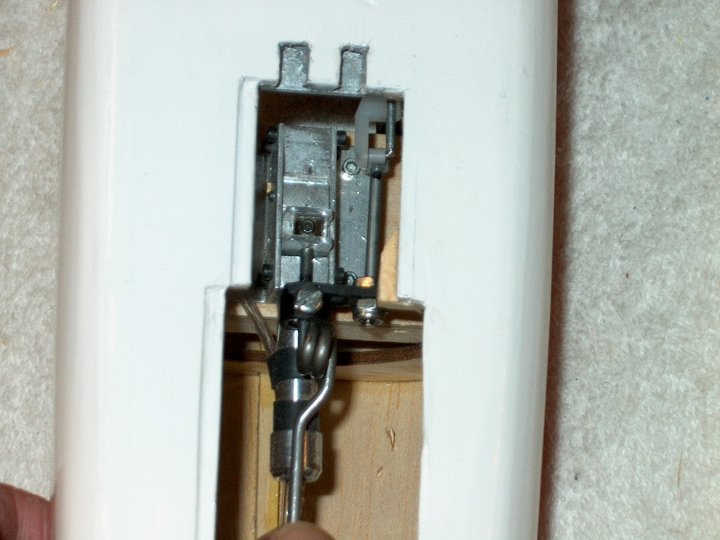
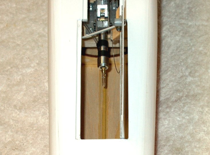
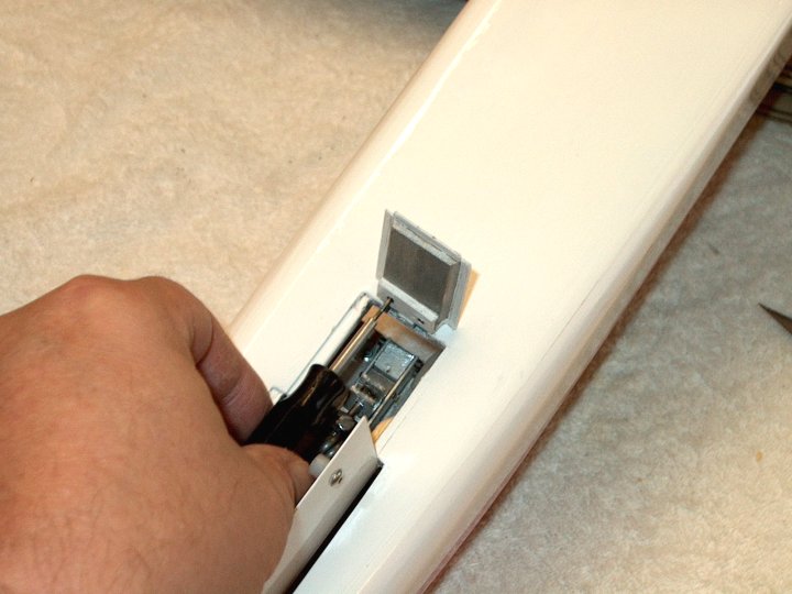
12 - The covering is trimmed from the
bottom of the fuselage. It will be replaced with White
covering once assembly is completed.
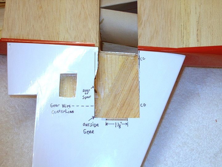
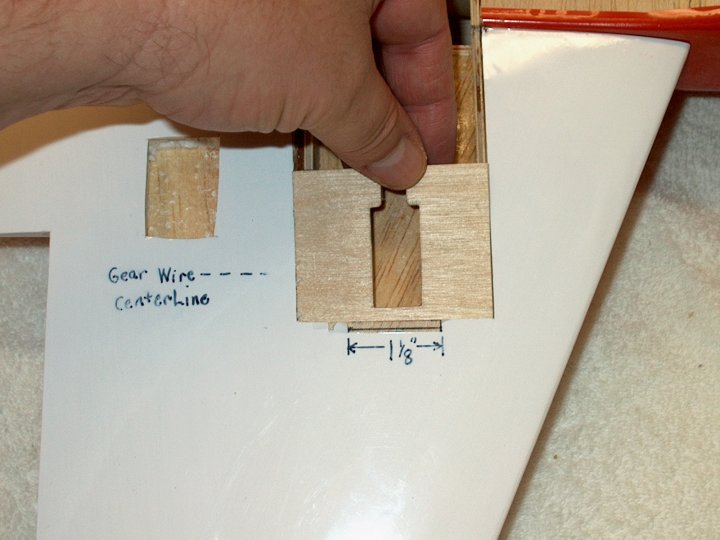
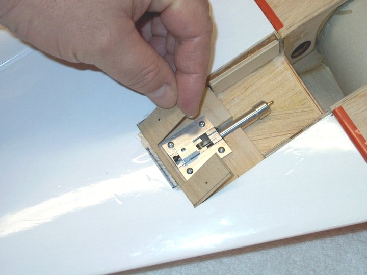
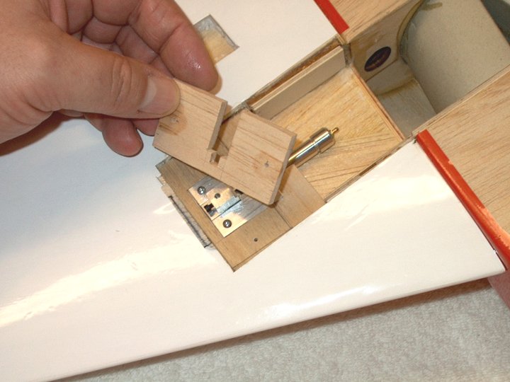
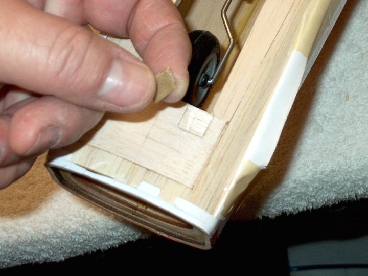
| |
13 - Covering being removed.
| |
14 - Covering removed from fuselage
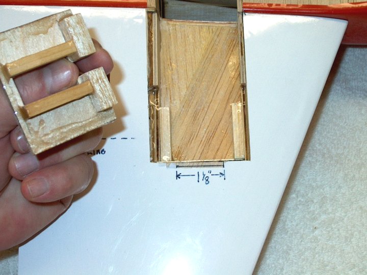
bottom. | |
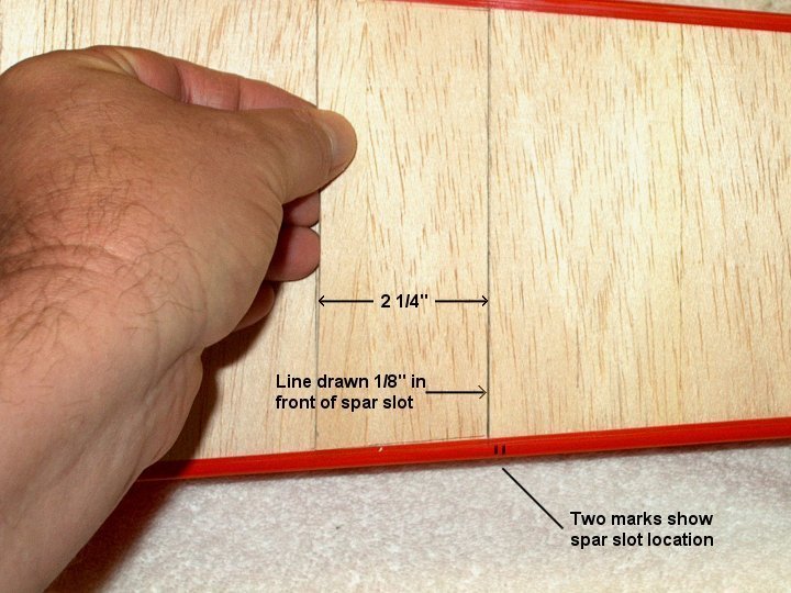
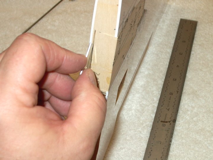
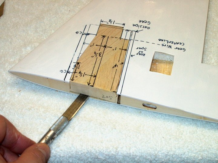
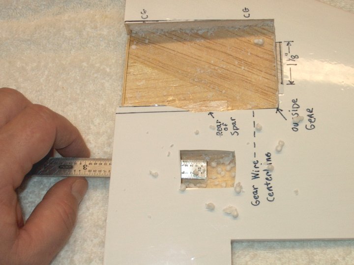
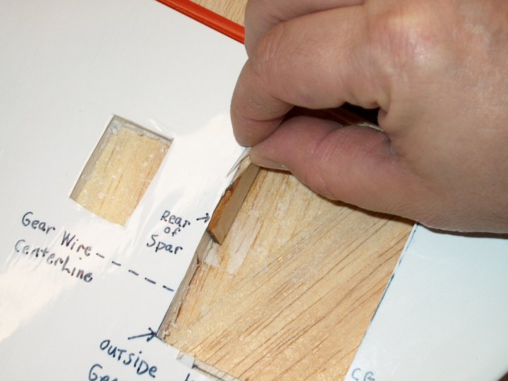
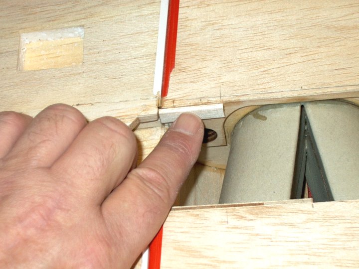
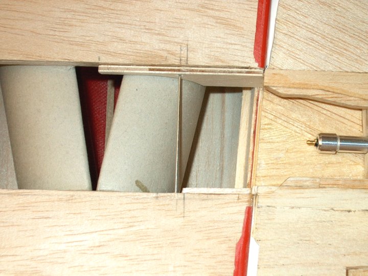
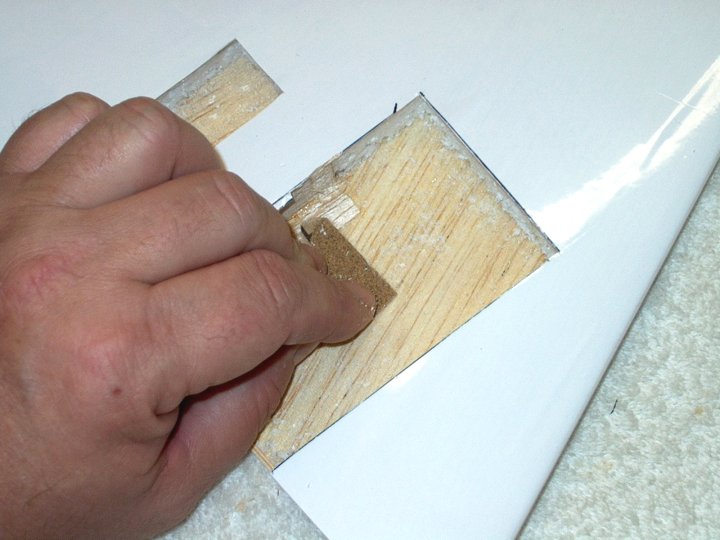
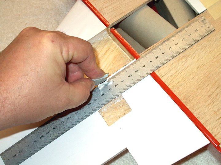
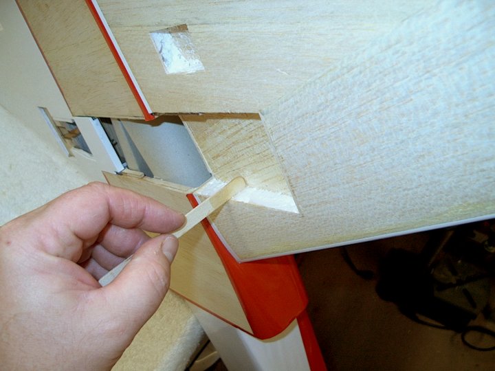
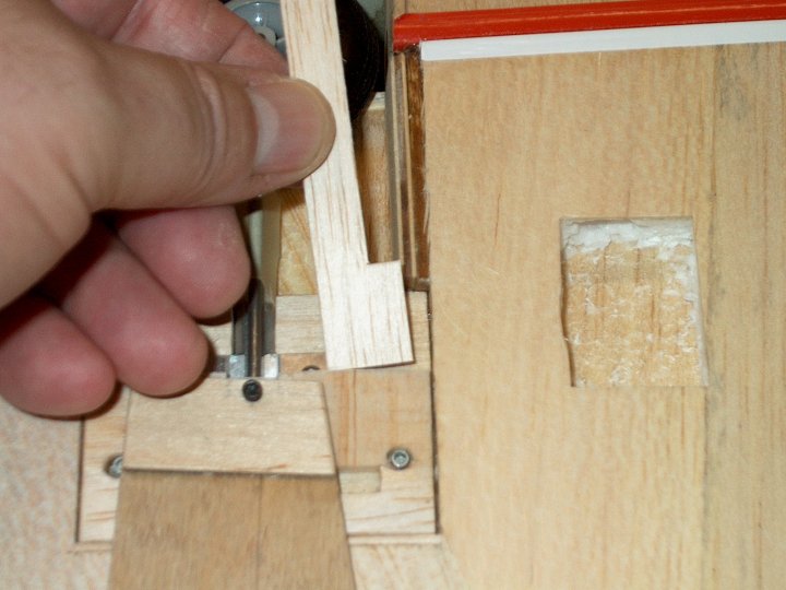
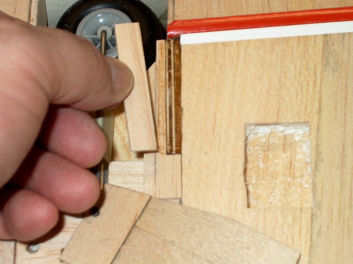
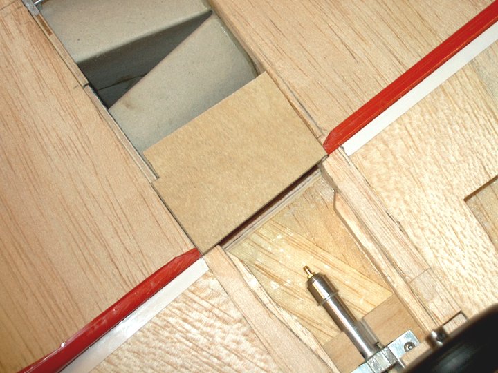
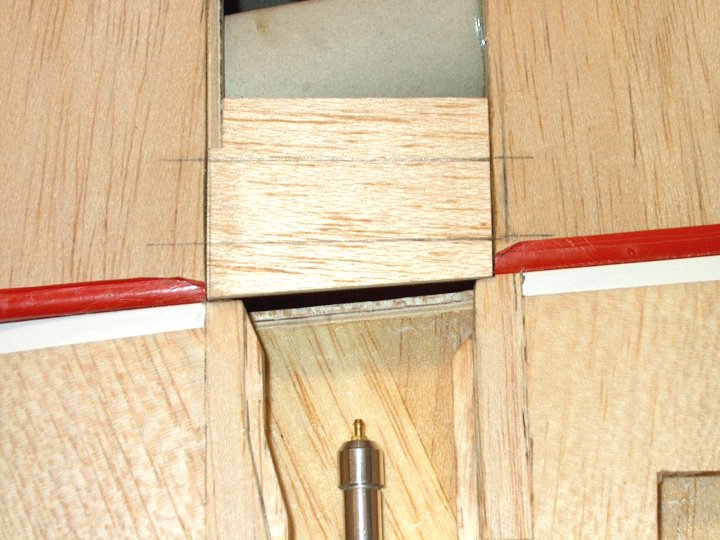
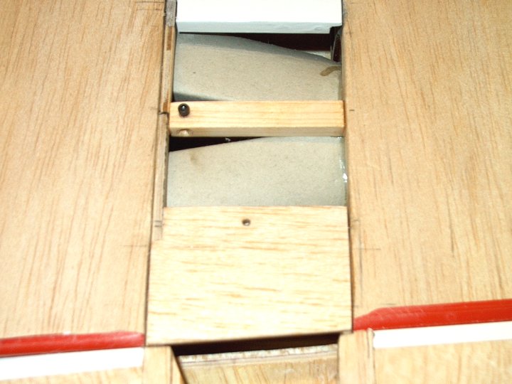
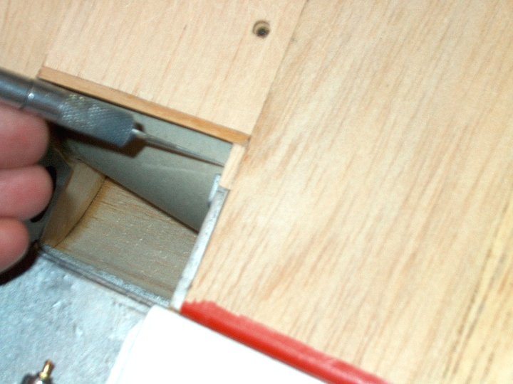
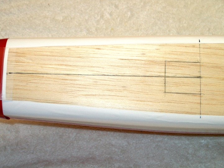
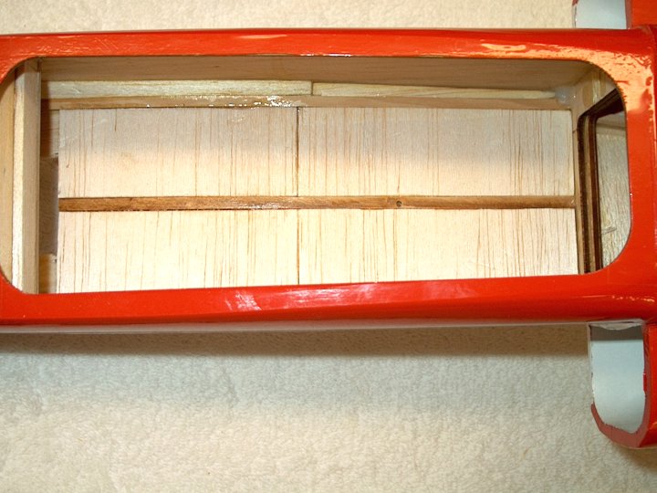
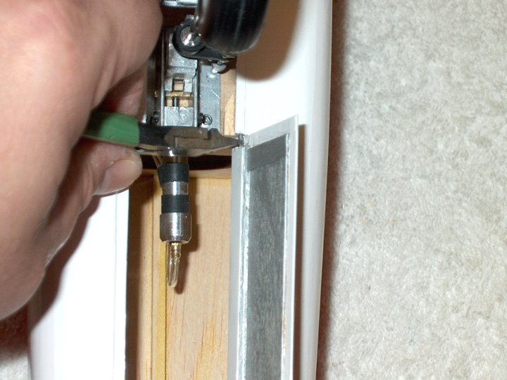
15 - Spar location is marked.
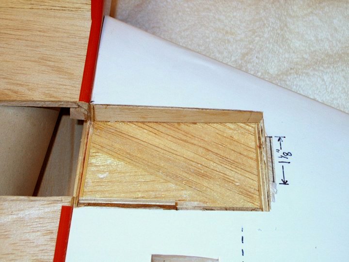
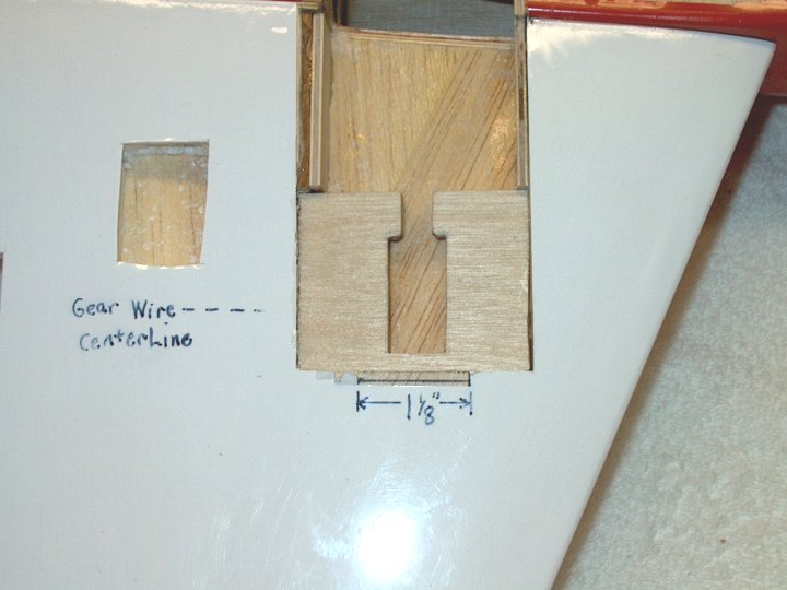
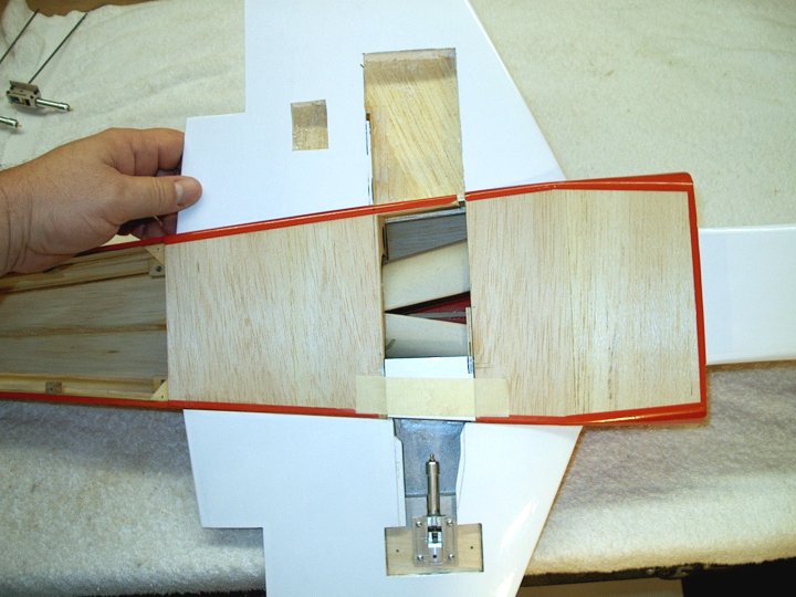
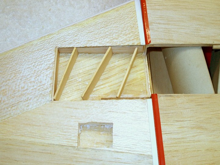
| |
16 - Second spar location marked.
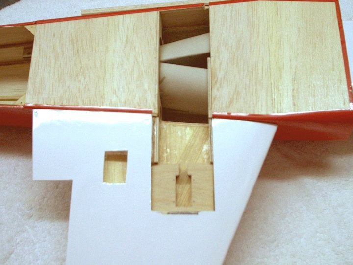
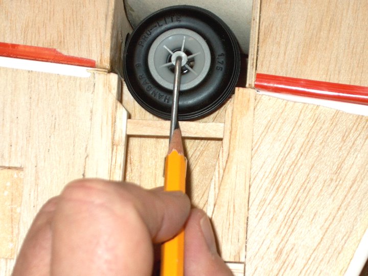
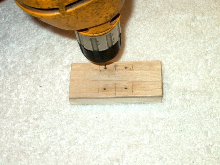
| |
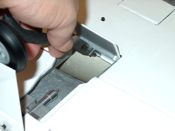
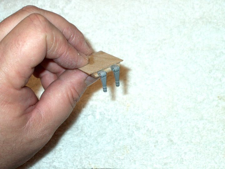
17 - A ruler is used to connect spar
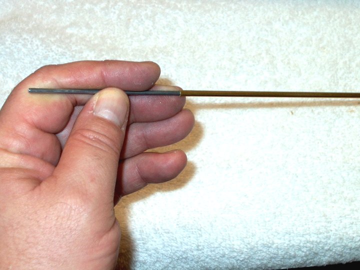
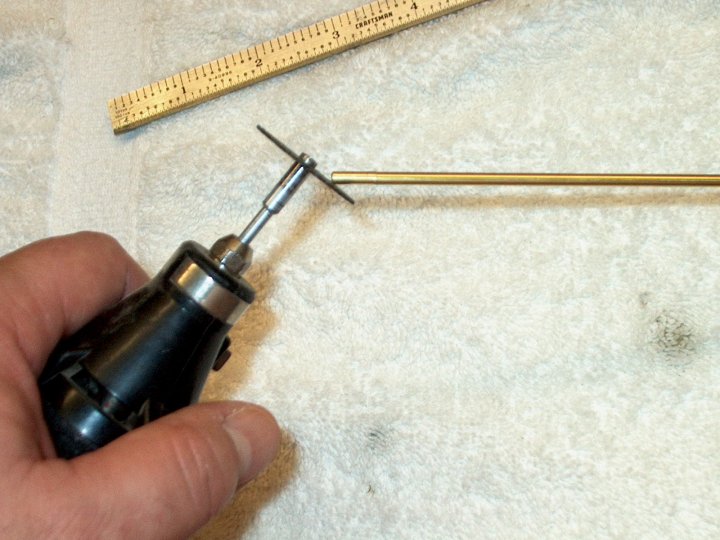
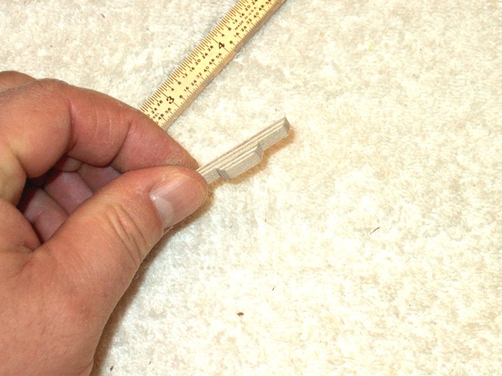
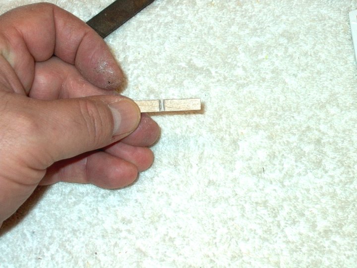
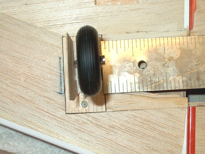
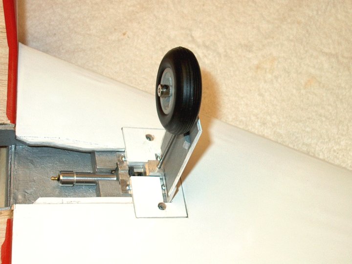
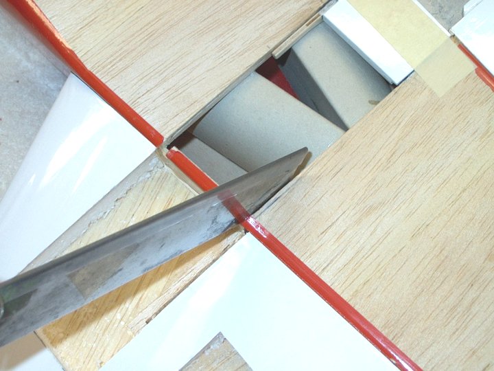
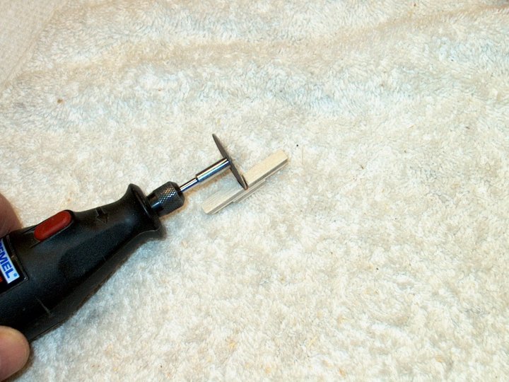
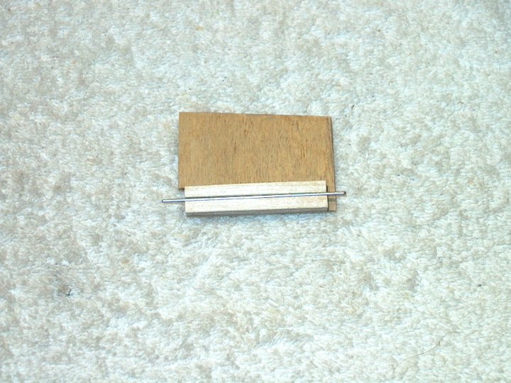
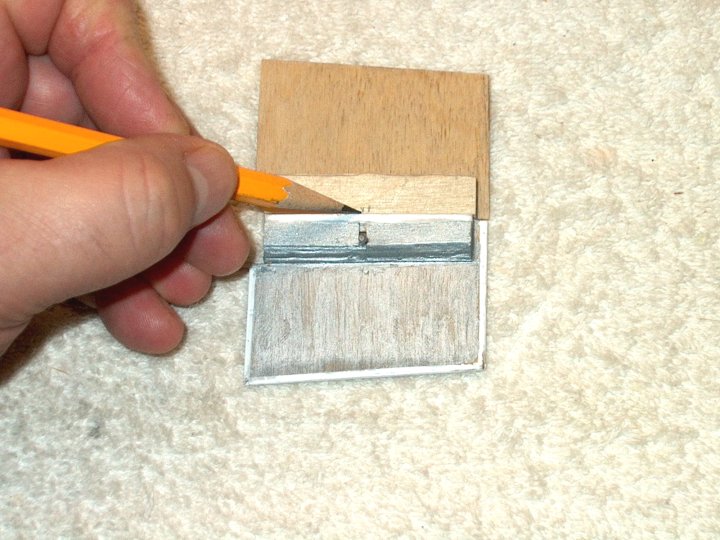
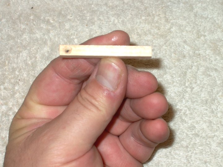
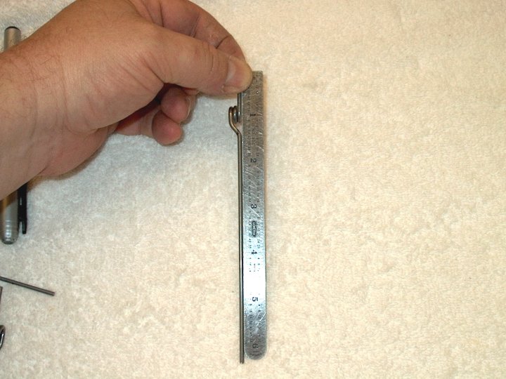
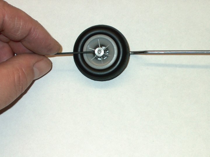
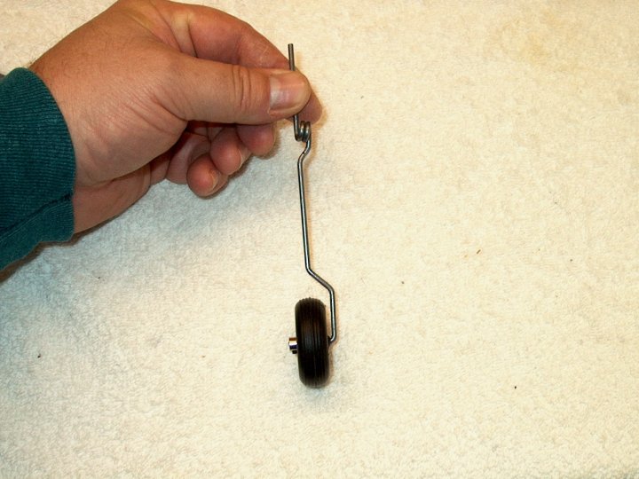
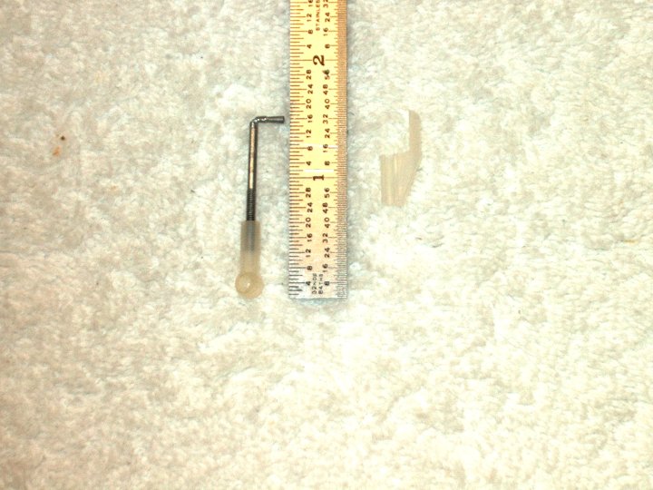
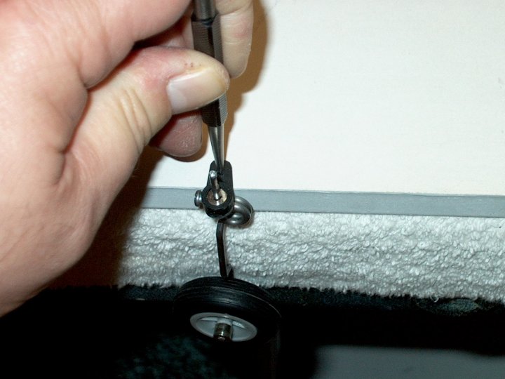
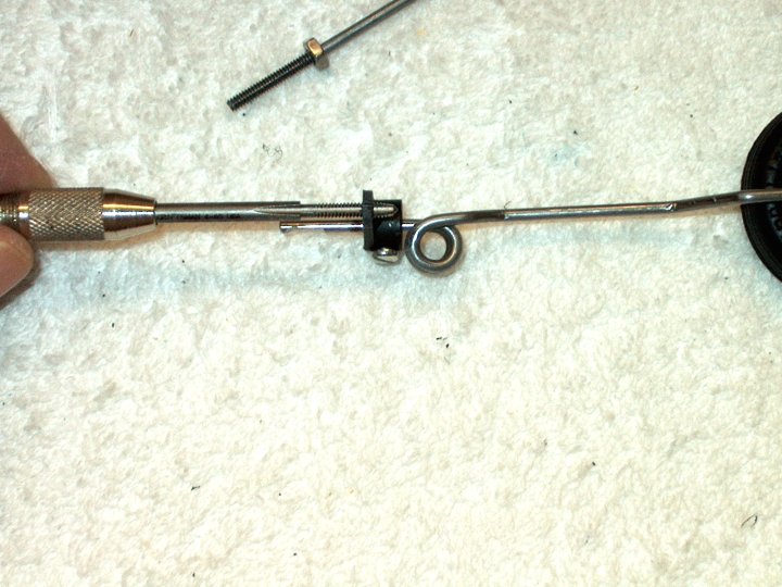
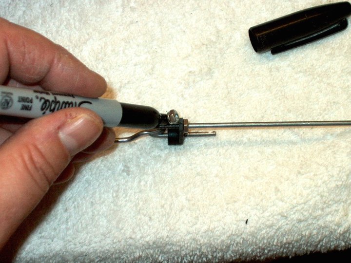
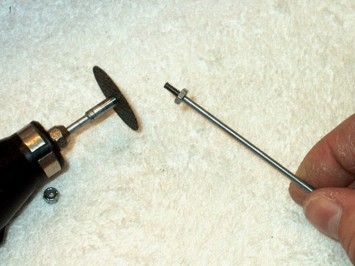
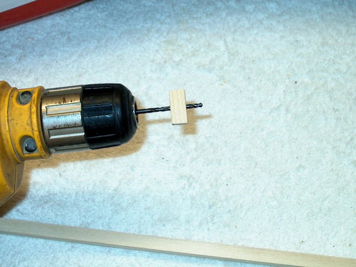
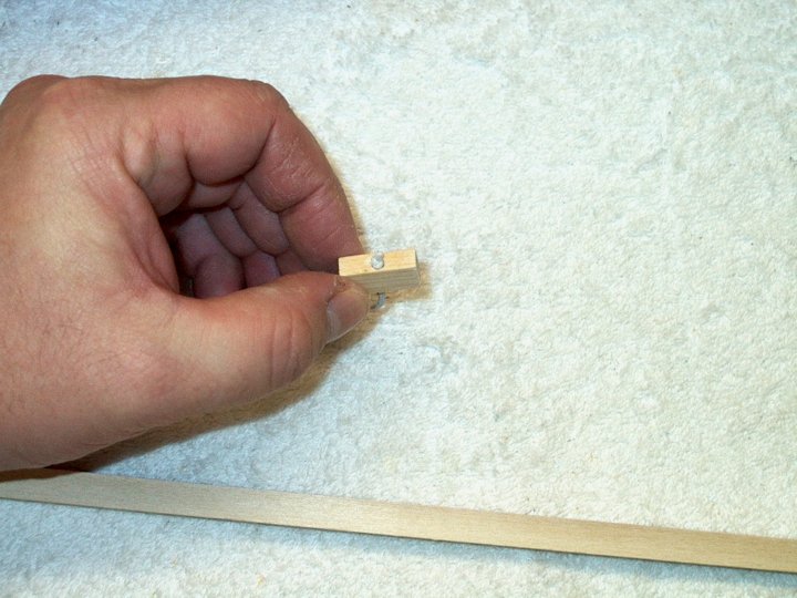
location marks on both sides. | |
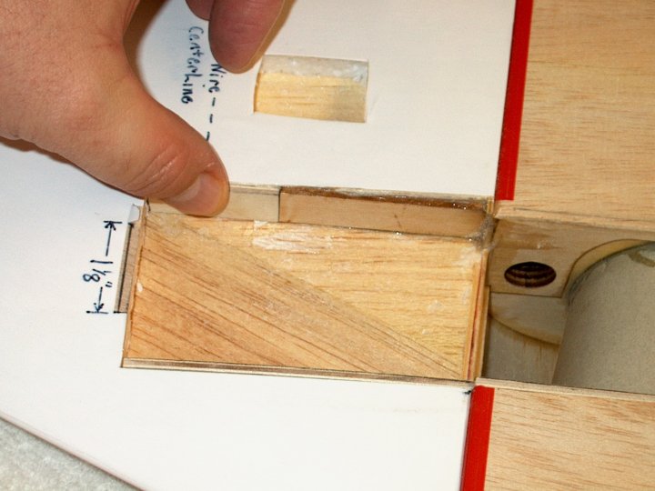
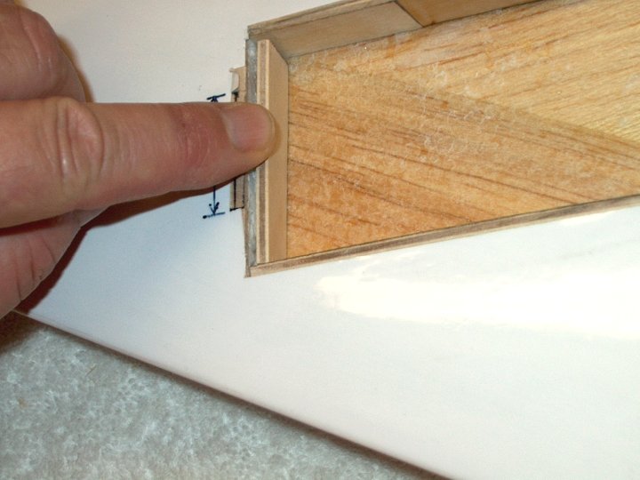
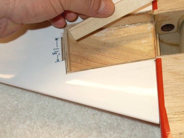
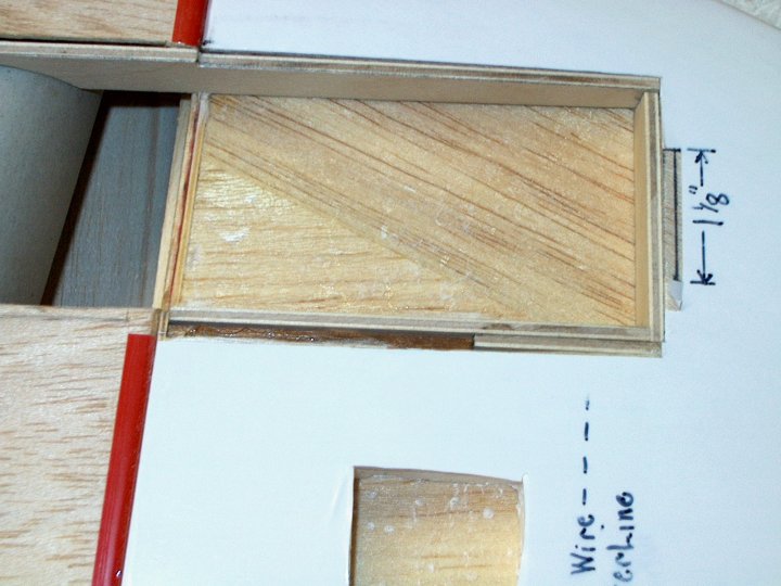
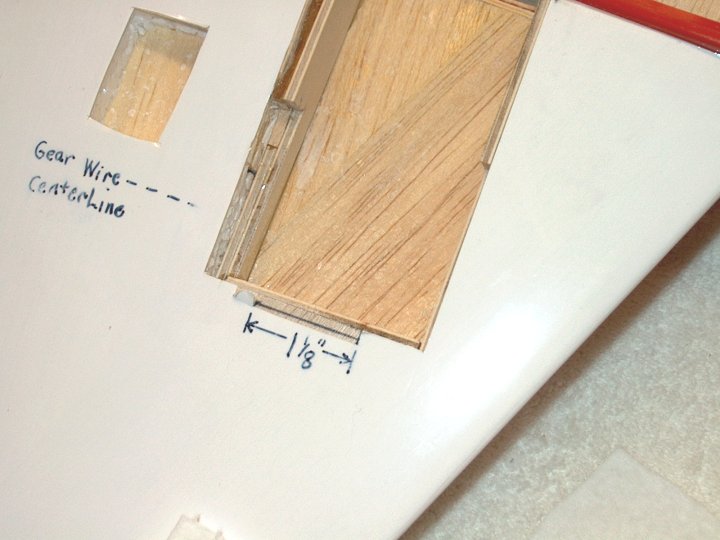
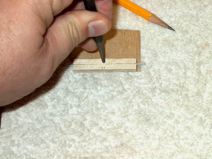
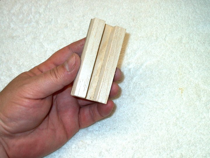
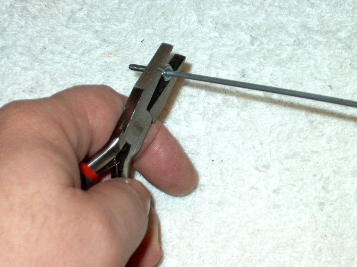
18 - Center strip, which was cut 1/8"
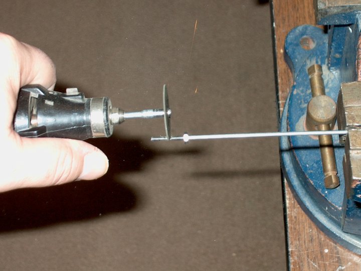
forward of the spar to spar line. A second line was drawn 2
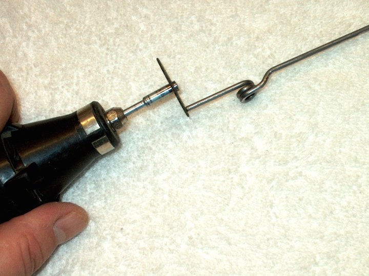
1/4" forward of the spar line (shown lifted on the left) and
the 2 1/4" wide strip of balsa sheet is removed.
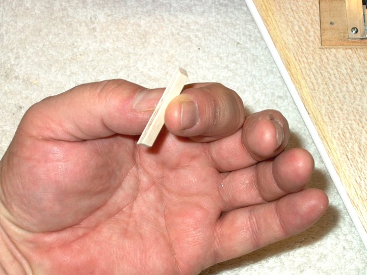
| |
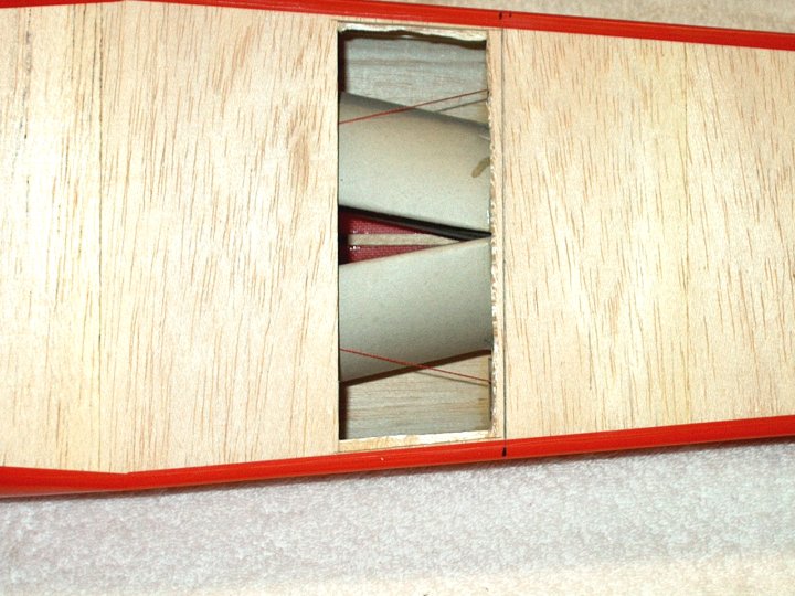
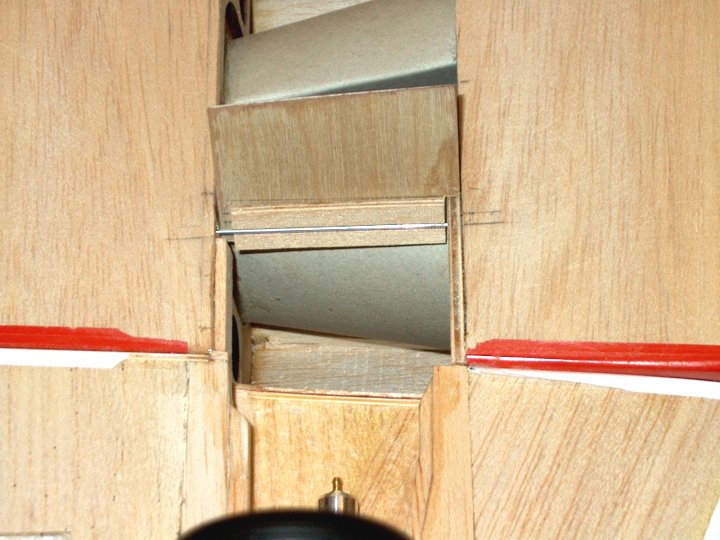
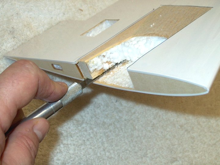
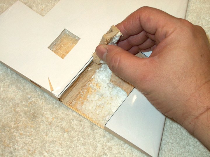
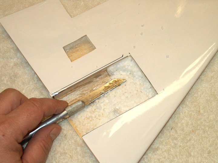
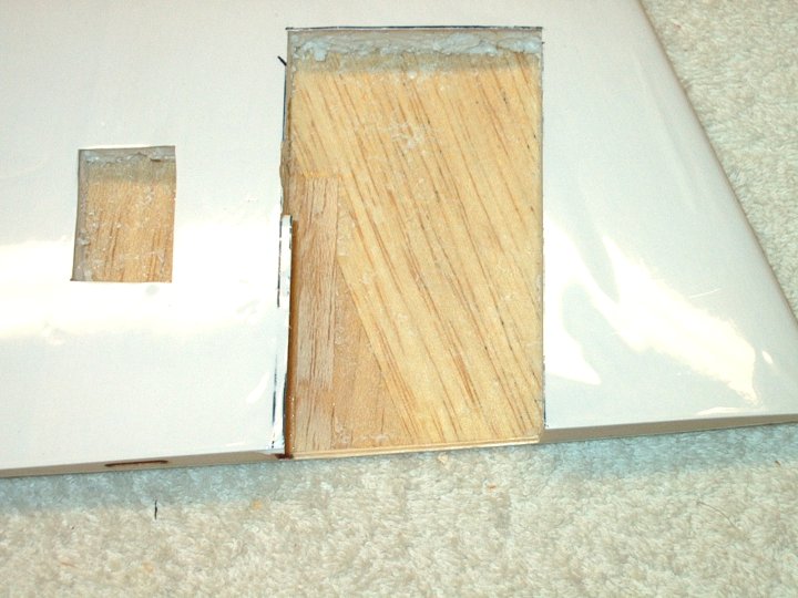
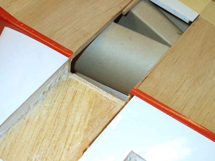
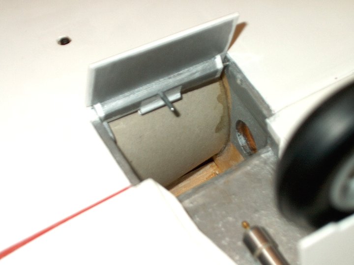
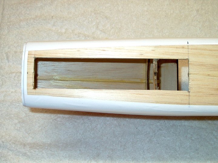
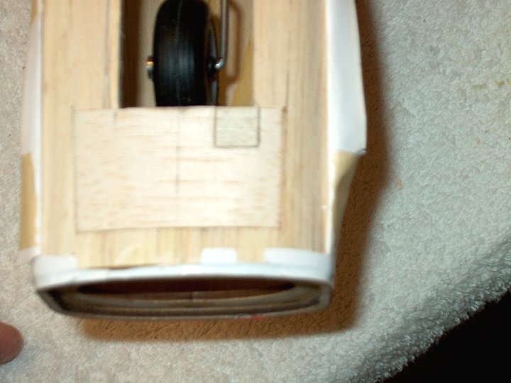
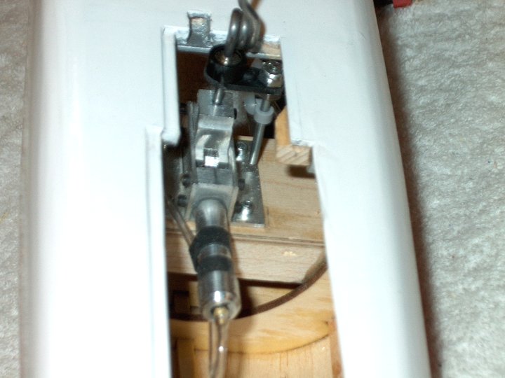
19 - Inside of fuselage is exposed.
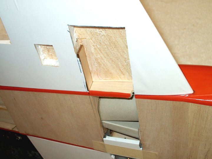
| |
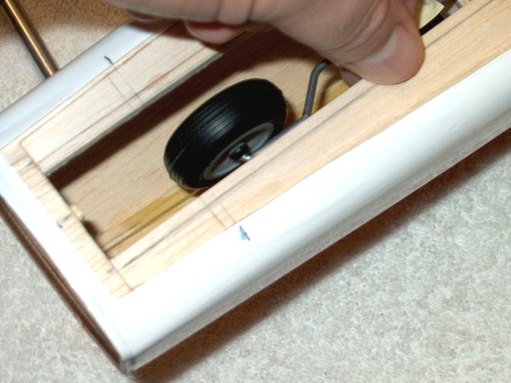
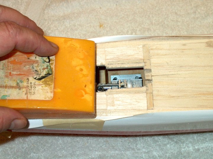
20 - Paper towel is wadded up to prevent
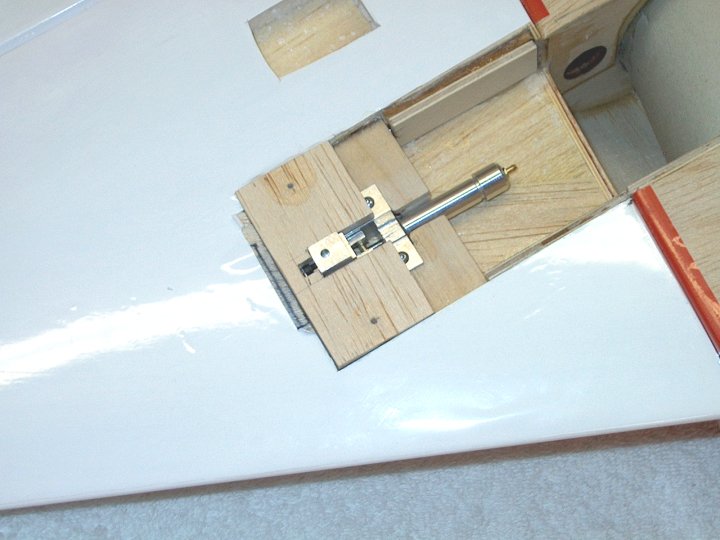
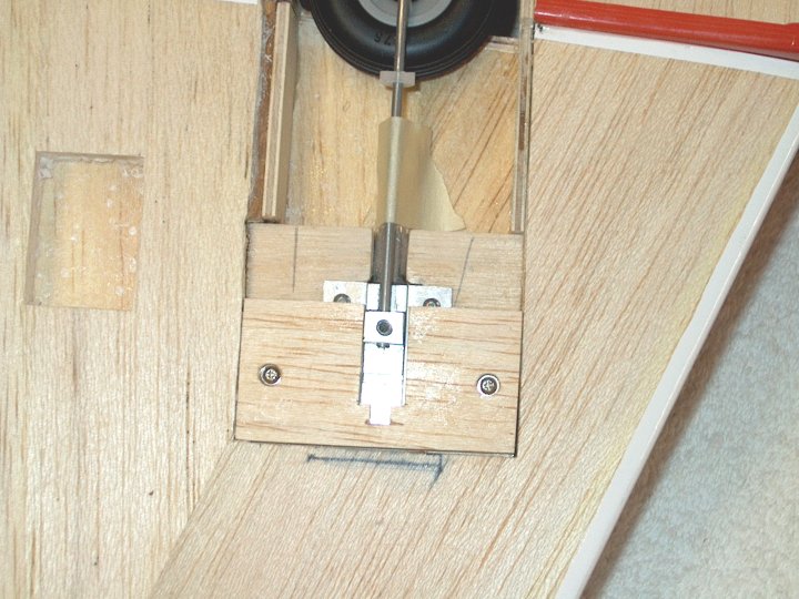
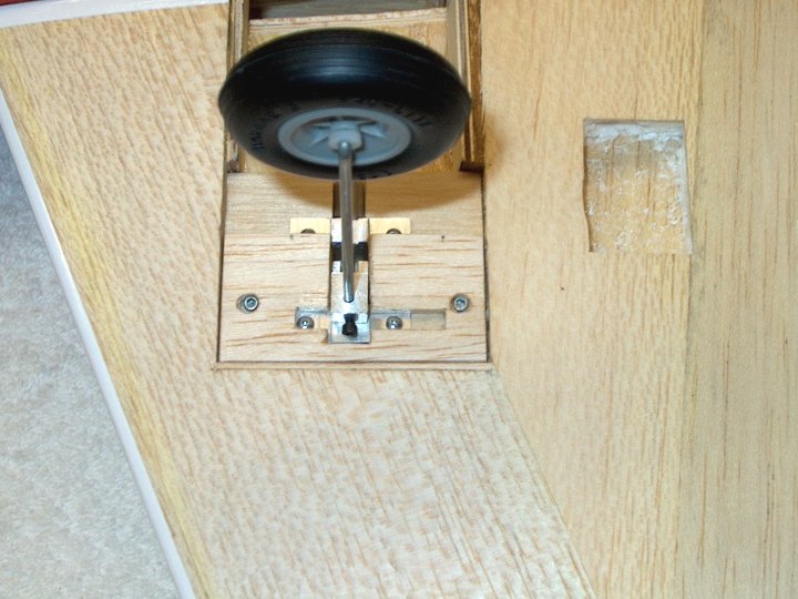
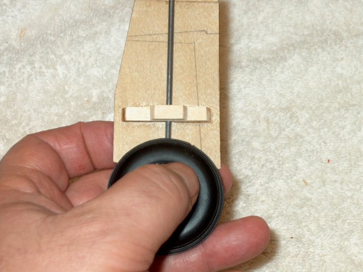
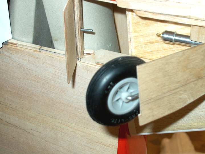
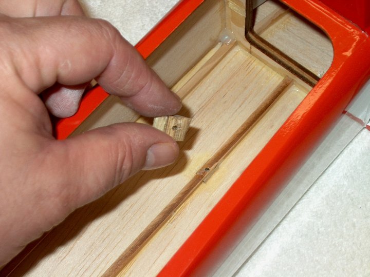
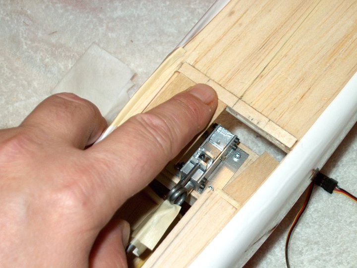
wheel from falling in while measuring.
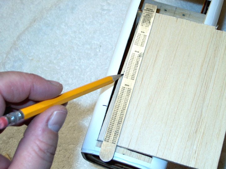
| |
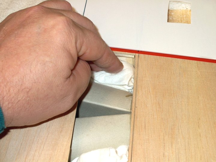
21 - Paper towel is wadded up to prevent
wheel from falling in while measuring.
| |
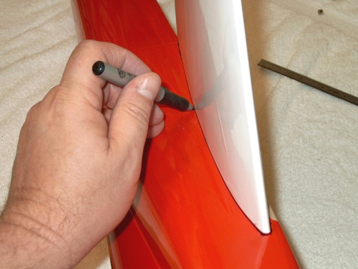
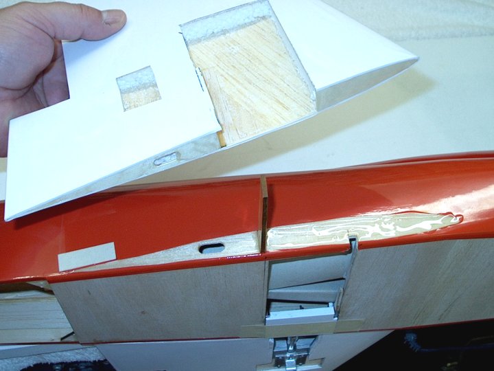
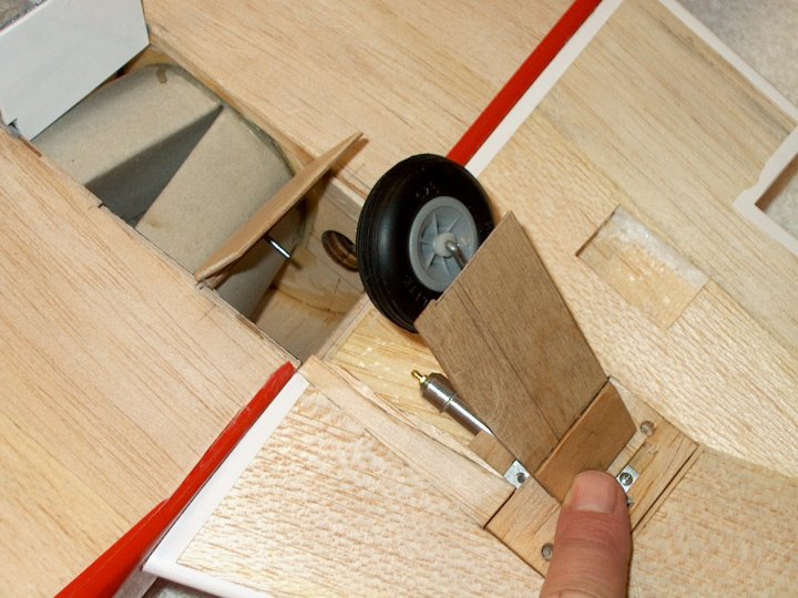
22 - Wing is placed on fuselage and marked
following normal instructions. | |
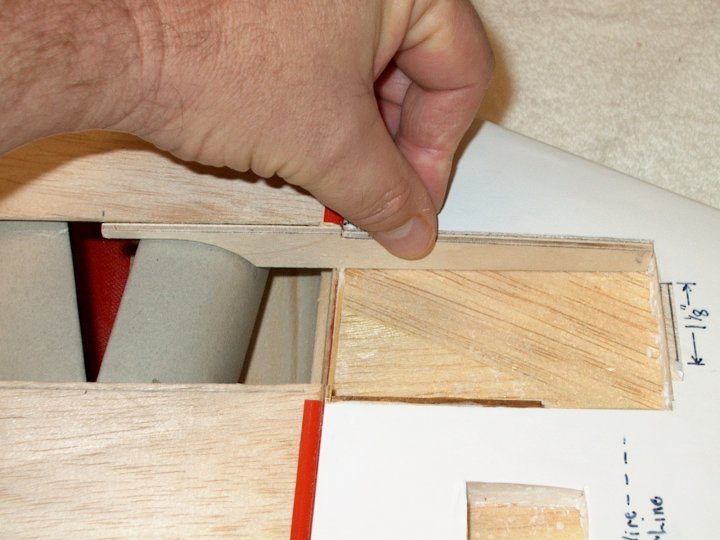
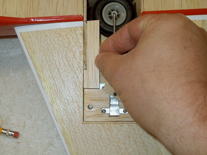
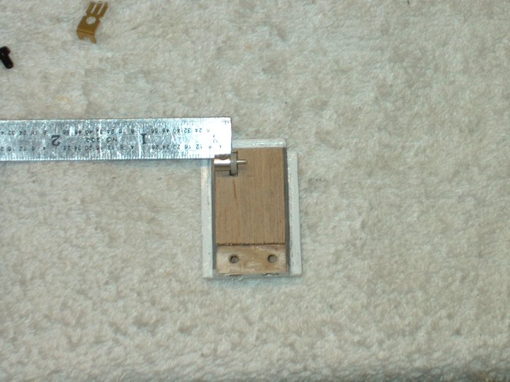
23 - Wing area shown marked.
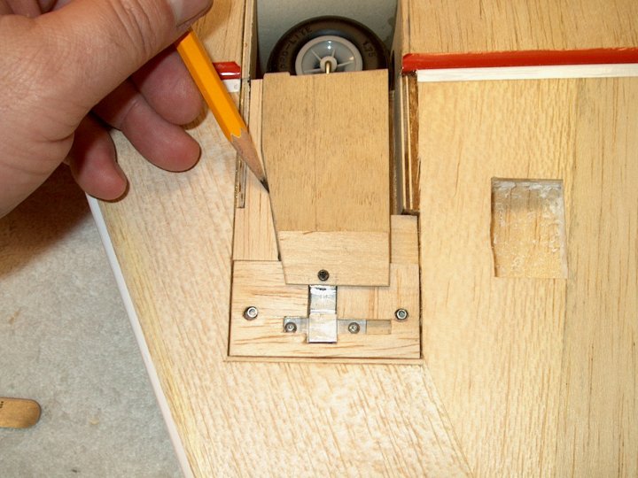
| |
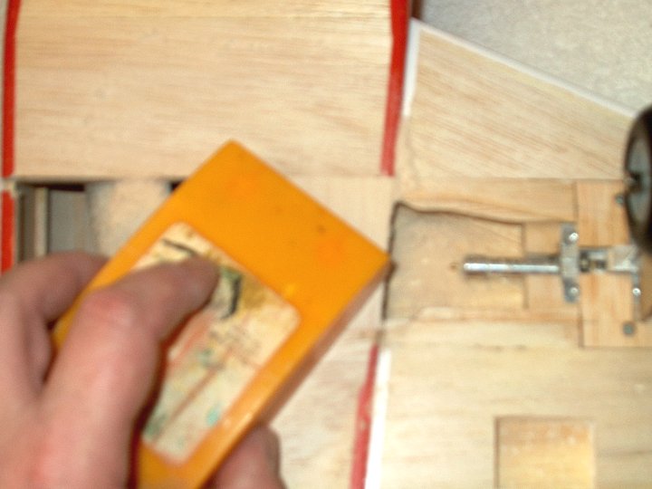
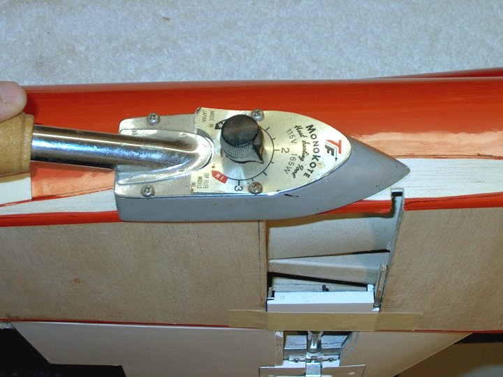
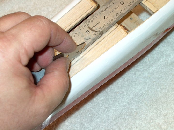
24 - Covering is ironed, removing any
wrinkles. | |
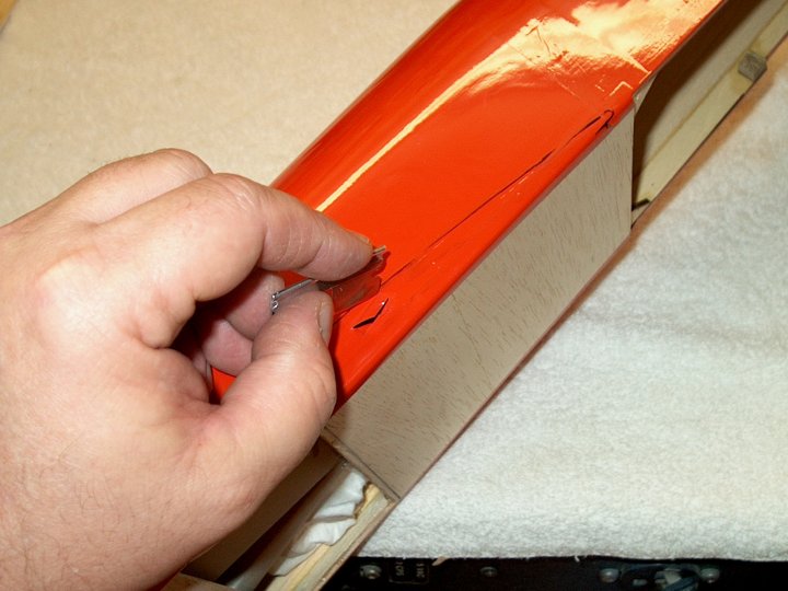
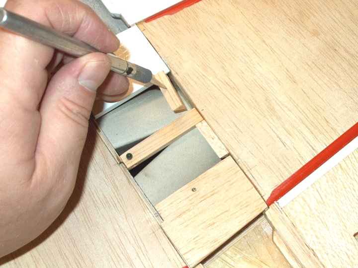
25 - A razor is used to remove the
covering where the wing will attach. Cut just inside the
line. | |
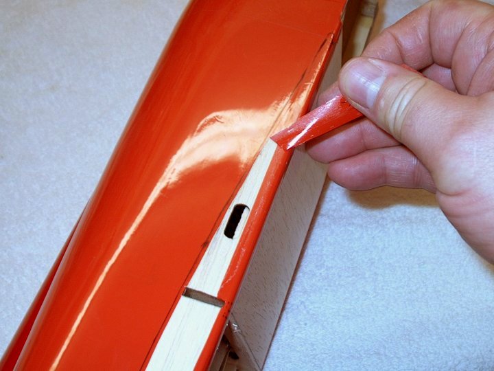
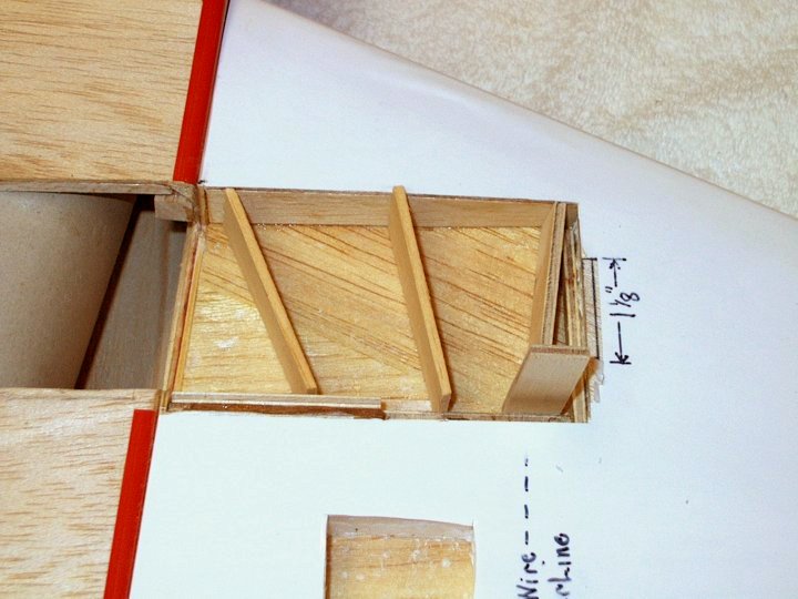
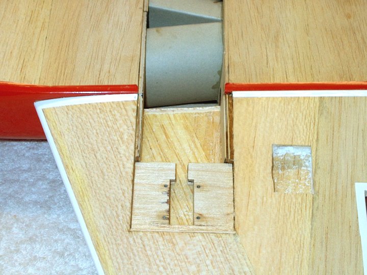
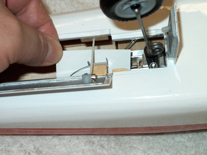
26 - Covering shown being removed from
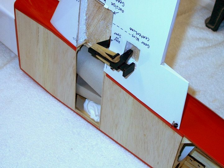
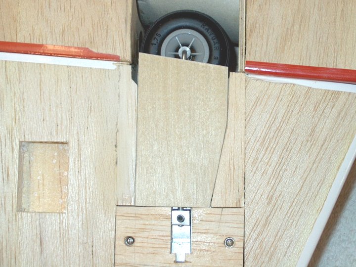
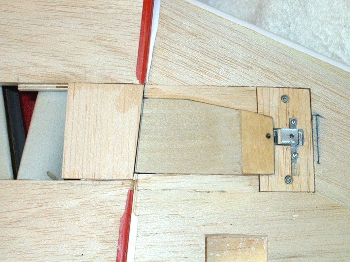
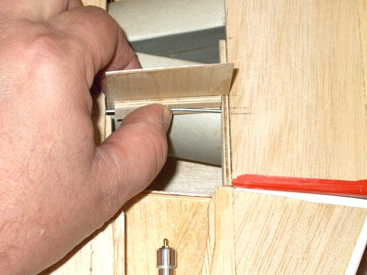
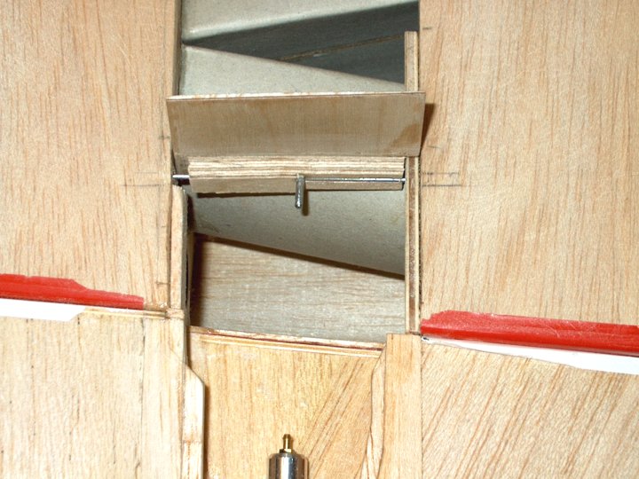
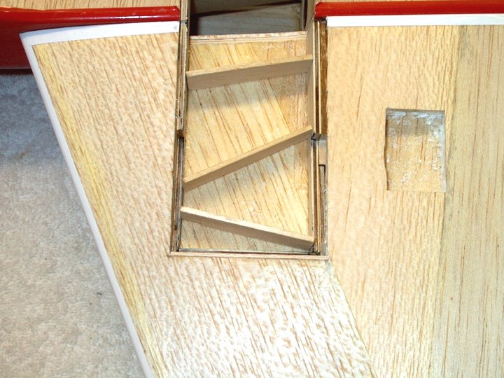
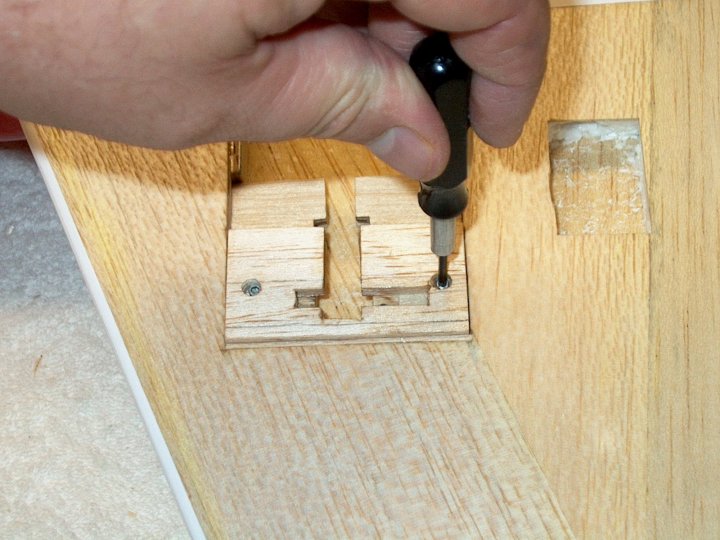
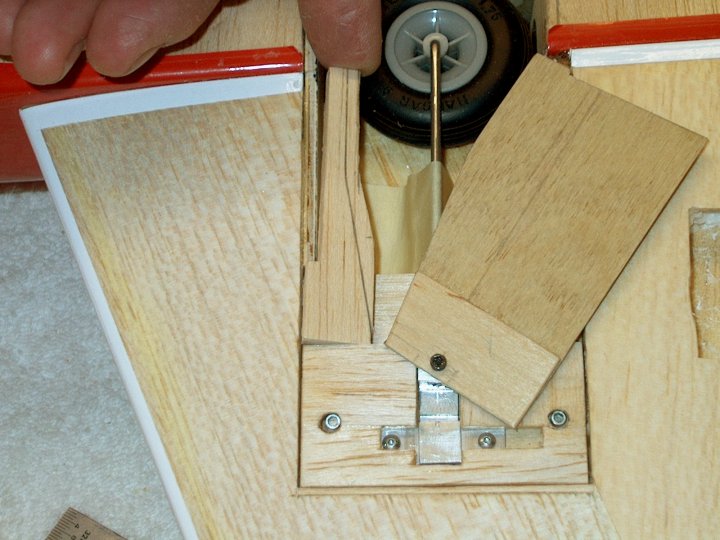
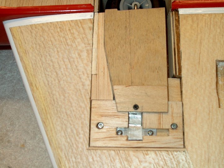
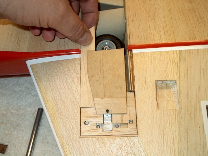
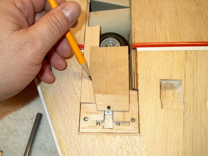
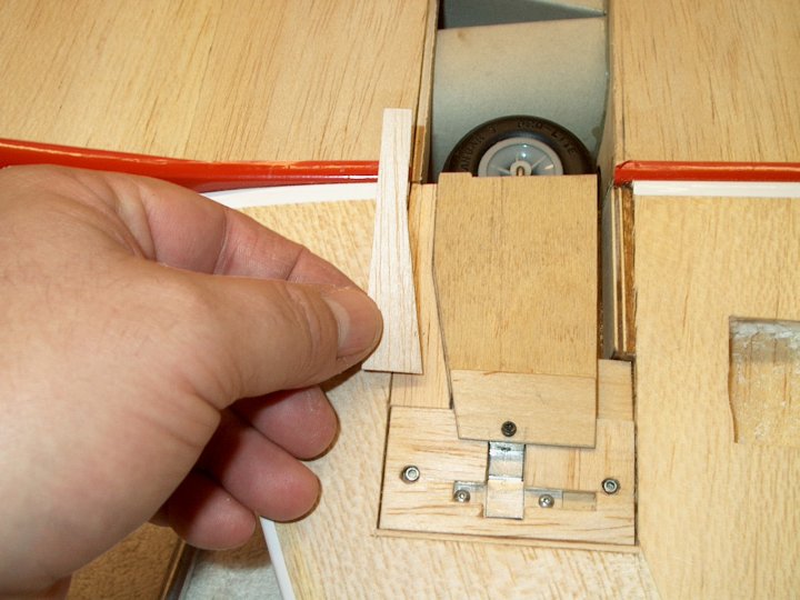
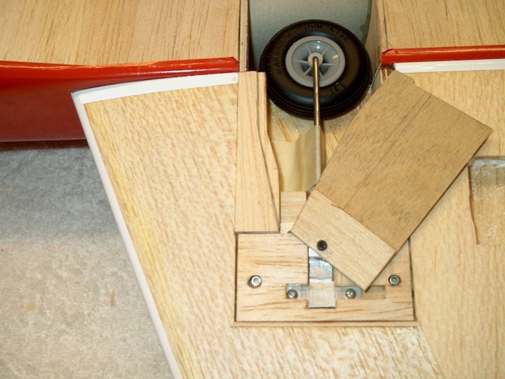
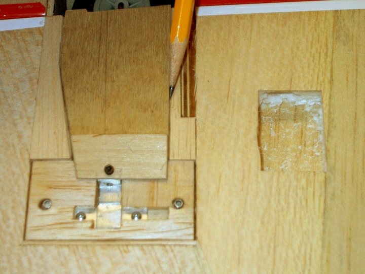
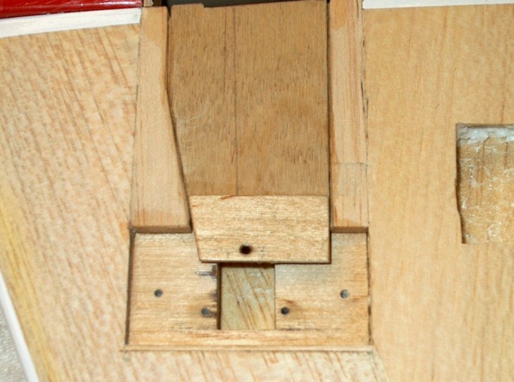
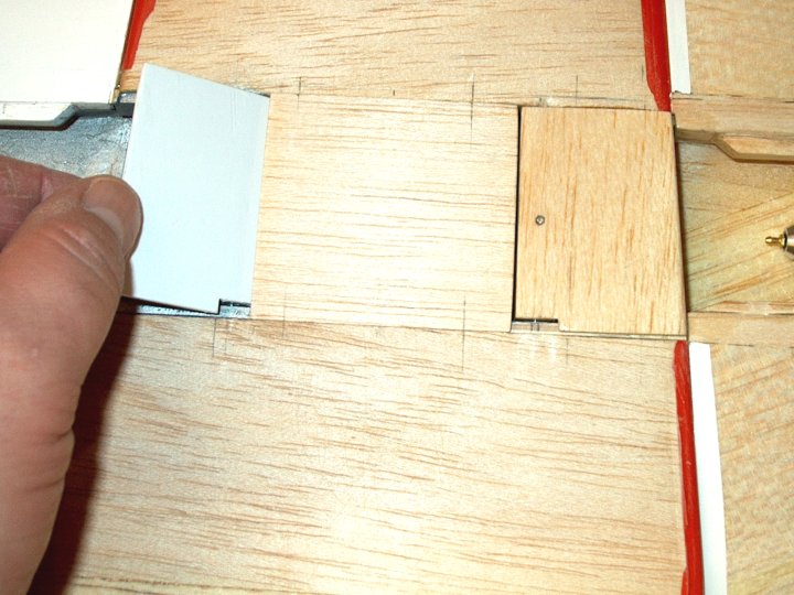
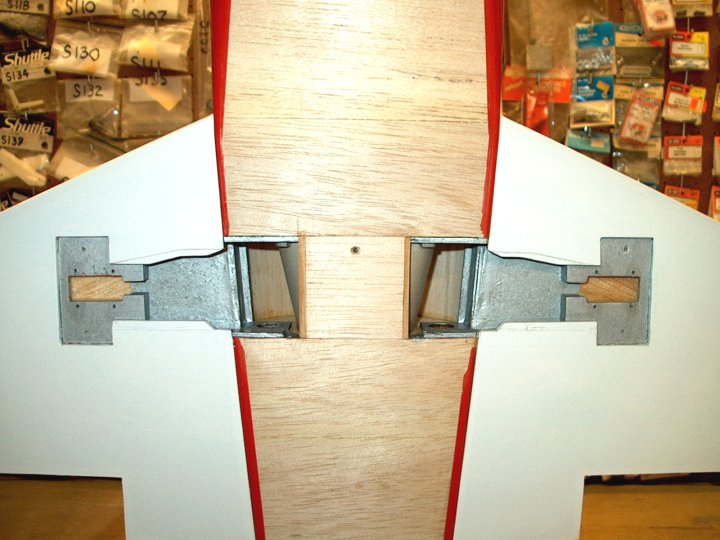
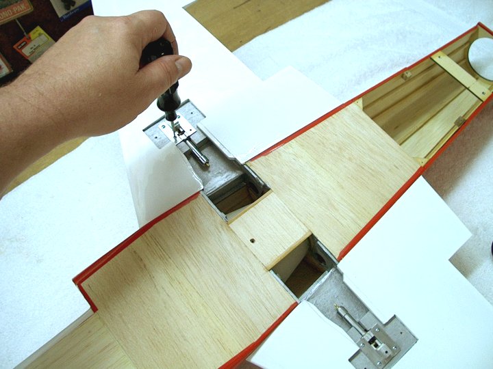
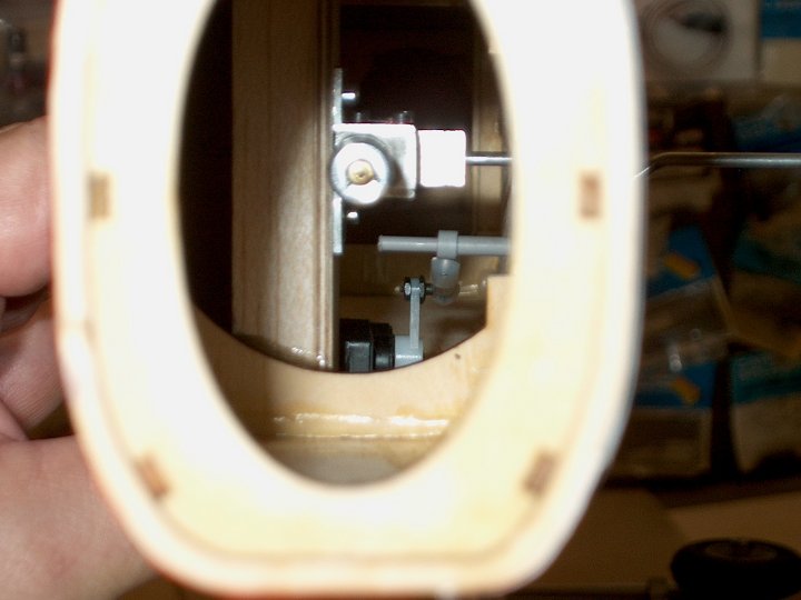
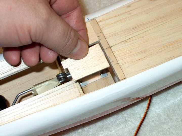
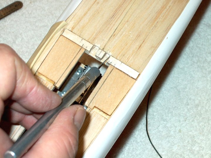
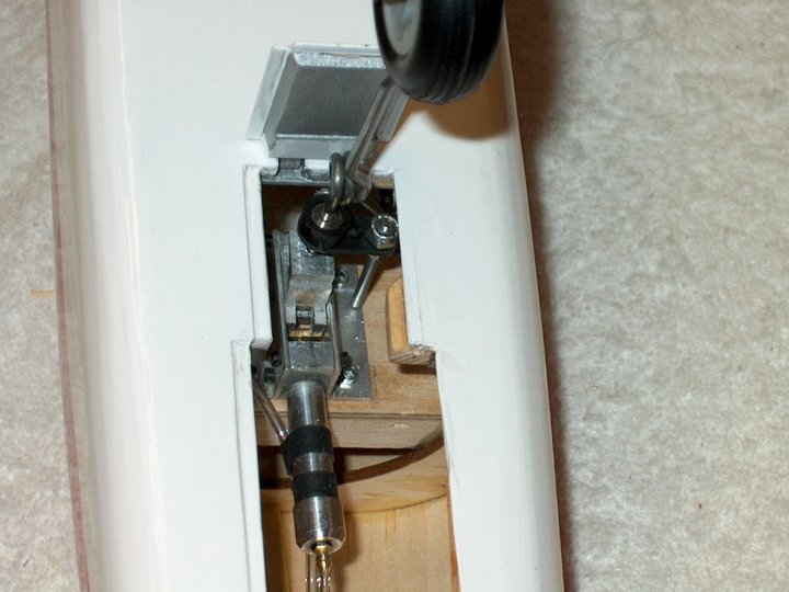
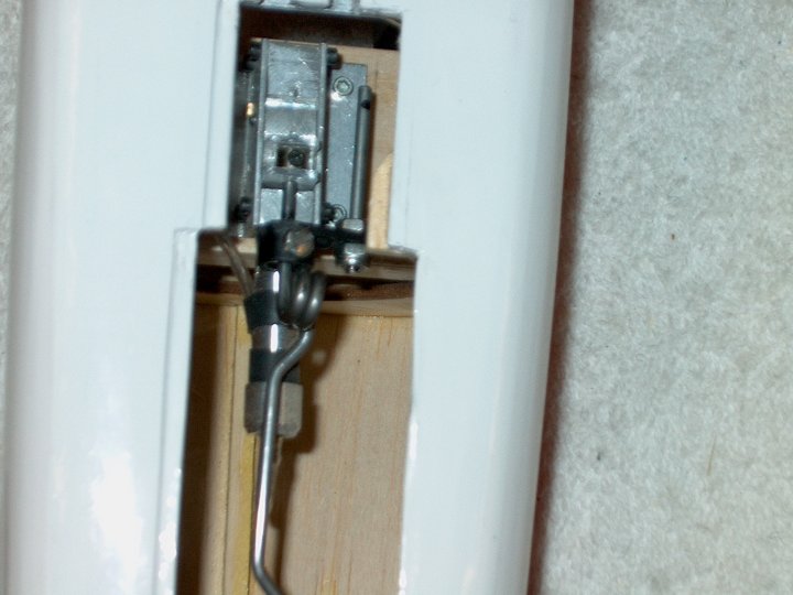
fuselage side. | |
27 - Fresh cut edges are ironed
down. | |
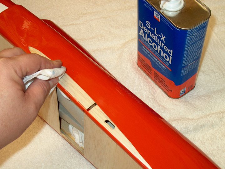
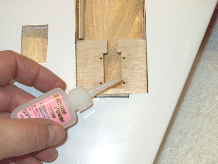
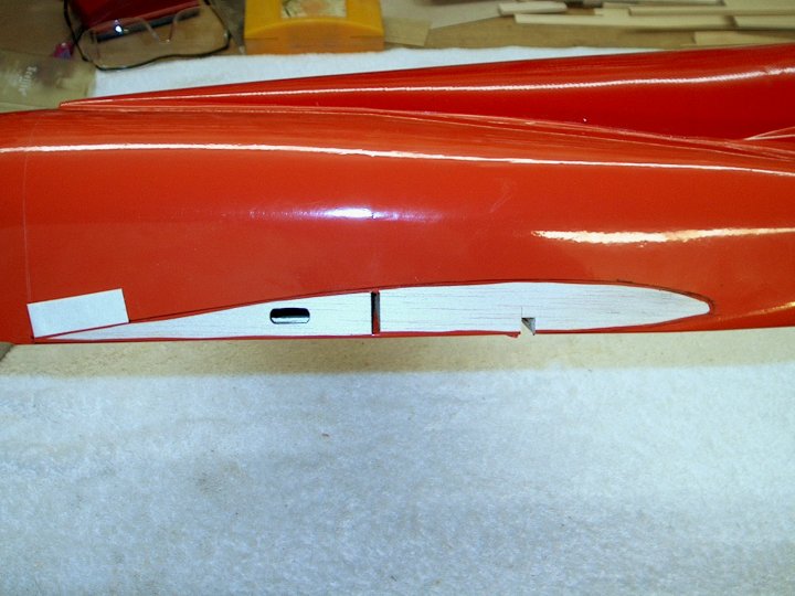
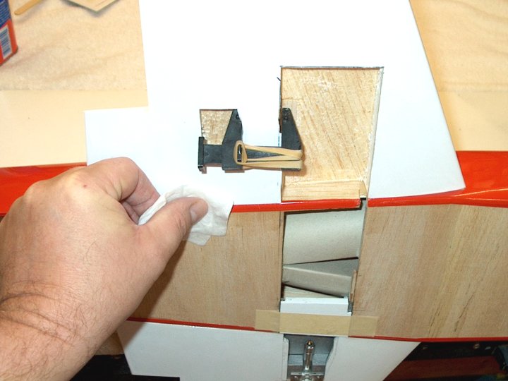
28 - Marker was cleaned off with denatured
alcohol and a paper towel. | |
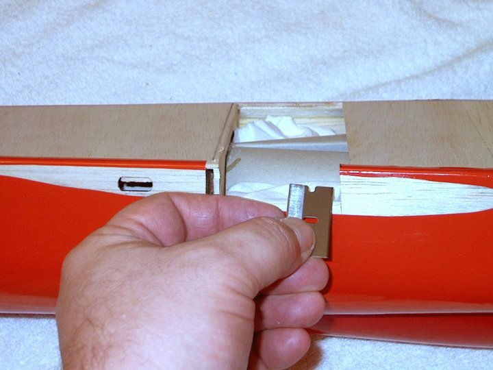
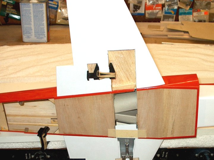
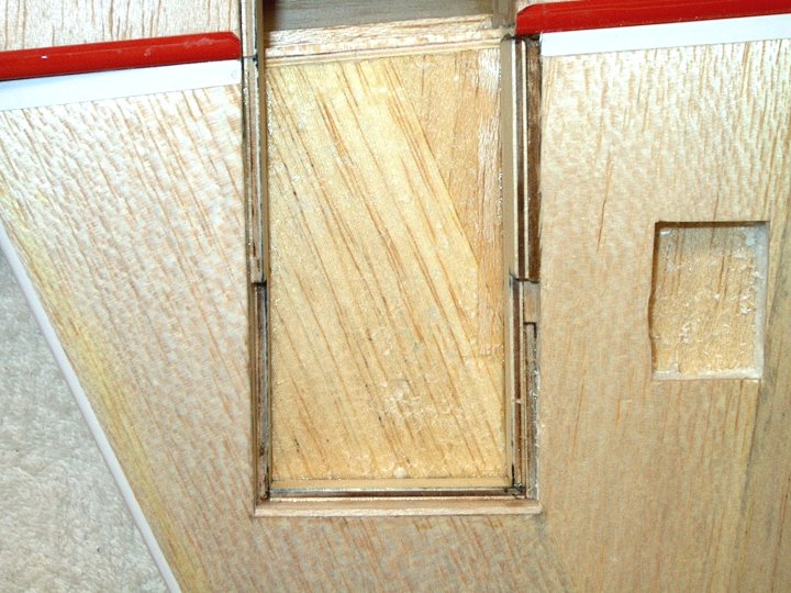
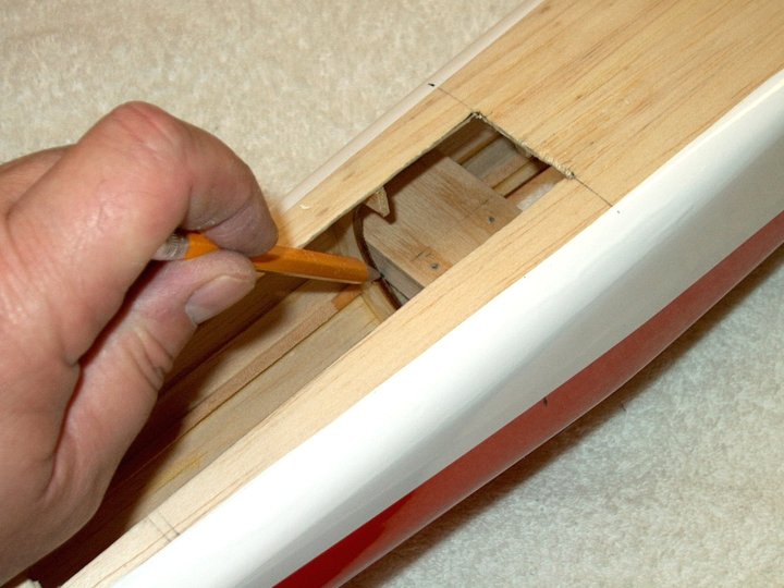
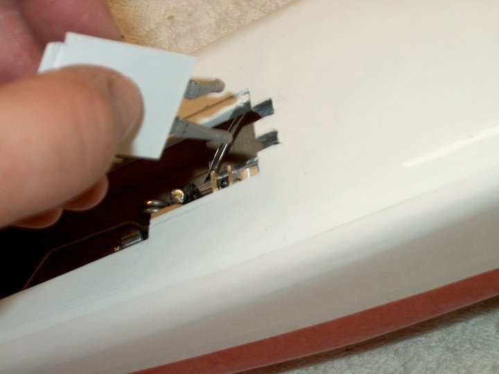
29 - Area for the retract is cut from the
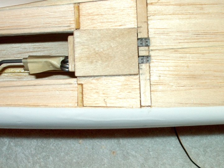
side of the fuselage. | |
30 - Excess balsa removed from Aileron
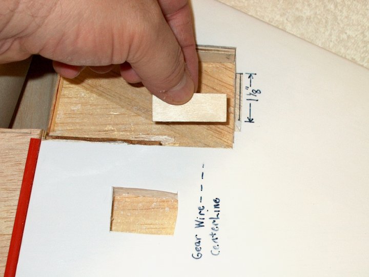
Servo wire hole in fuselage. It is a good time to enlarge this
slot and make sure it aligns with the wing slot so the wires
will feed through without binding. | |
31 - Foam removed from Aileron Servo wire
hole in wing. | |
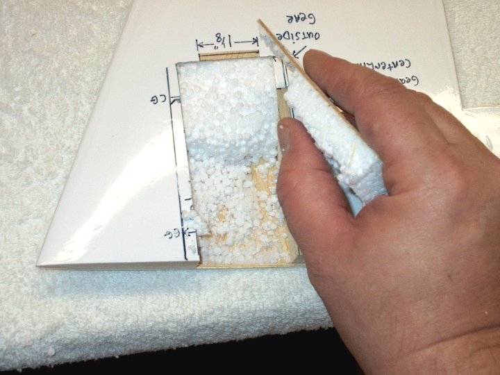
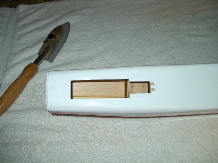
32 - Wing Initial measurements for
Retract. Bare Balsa show the shape how the door will be
cut. | |
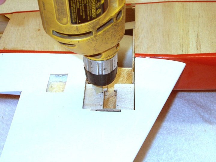
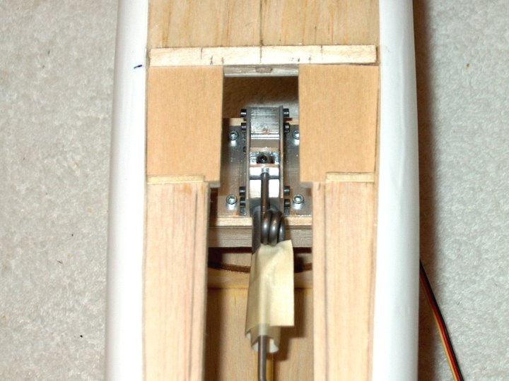
33 - Removing the area in the wing.
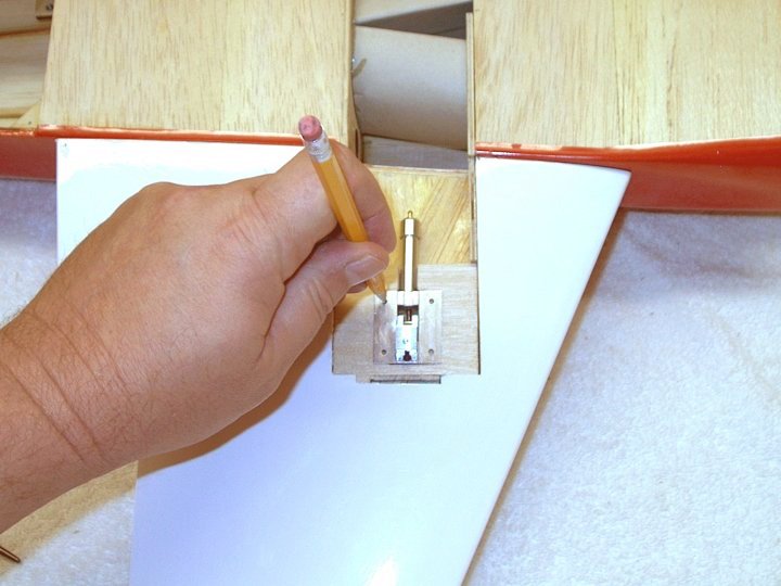
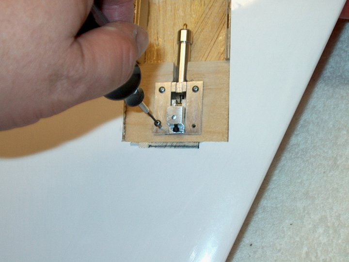
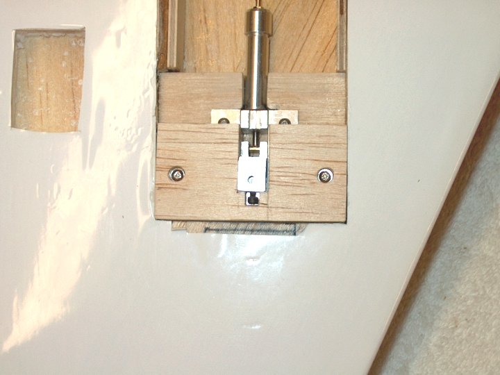
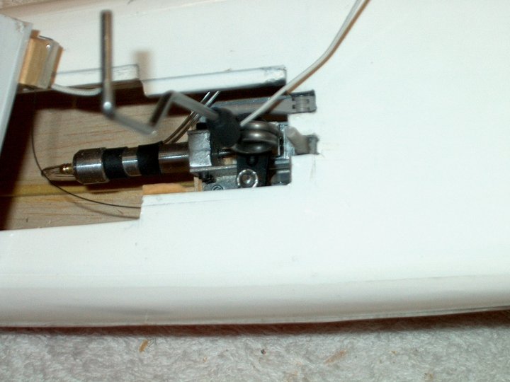
| |
34 - Initial cut shown and final forward
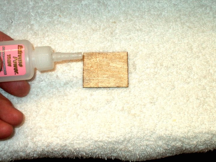
cut must be made at the CG line. | |
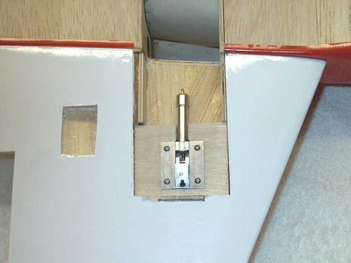
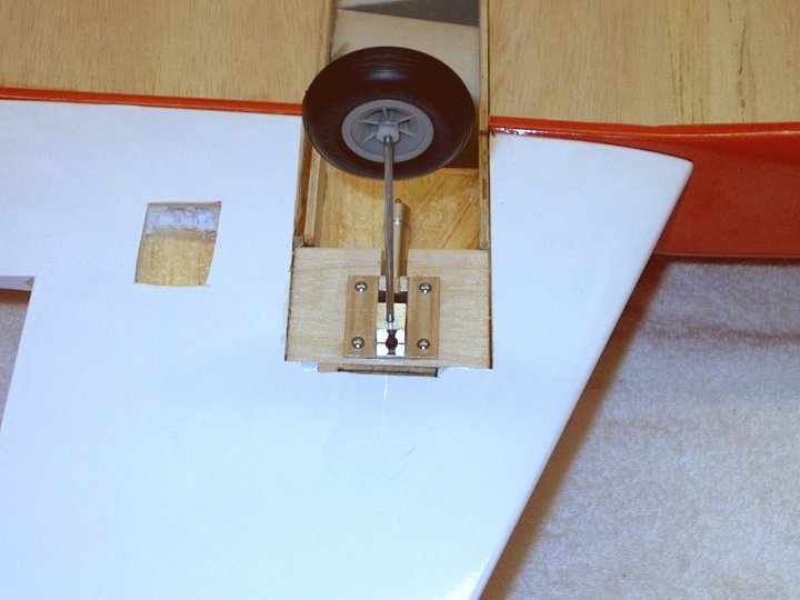
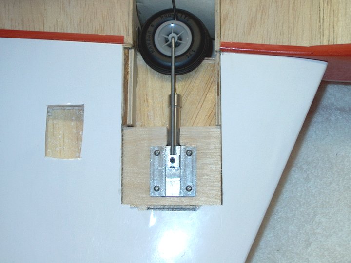
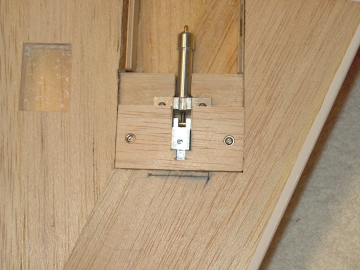
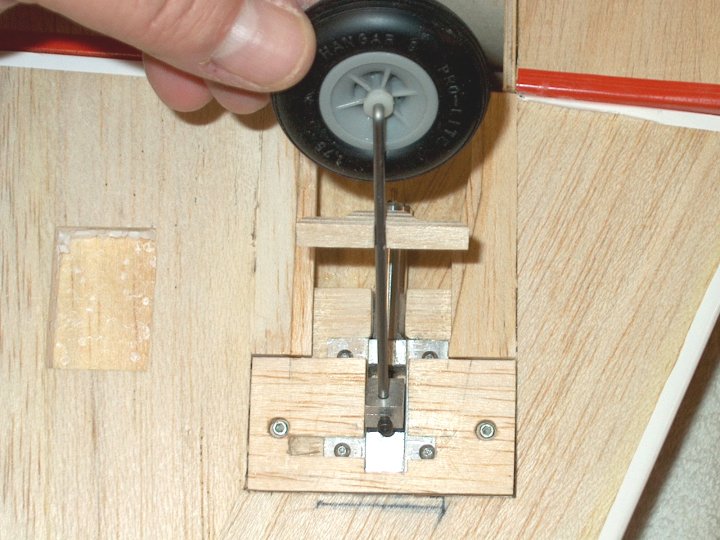
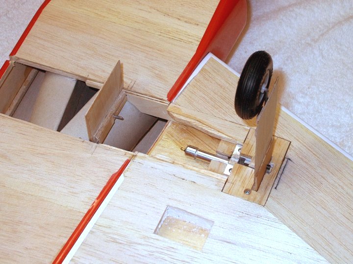
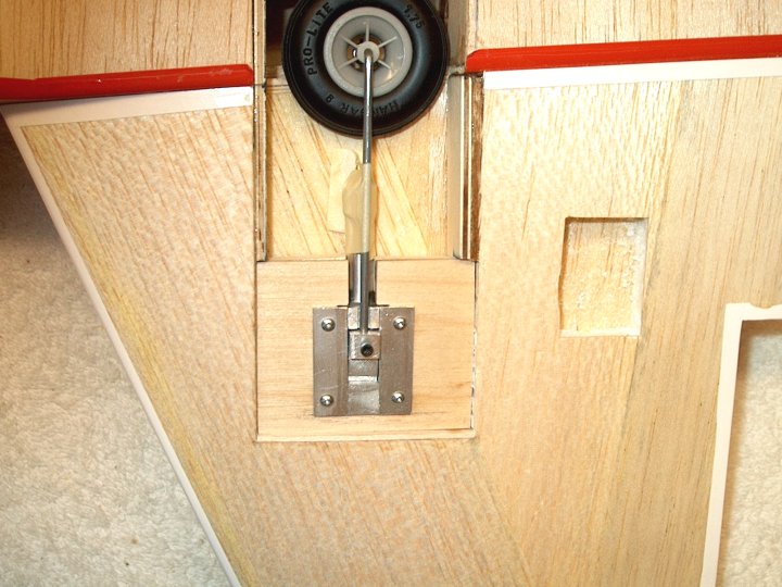
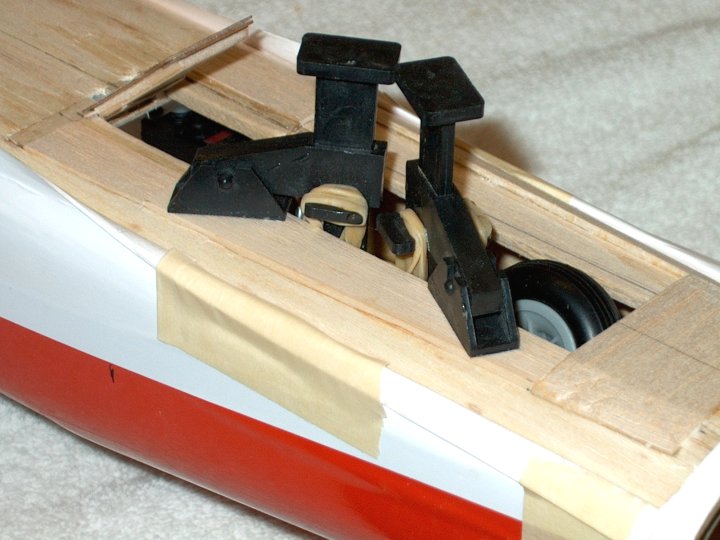
35 - Area cut and ready to remove.
| |
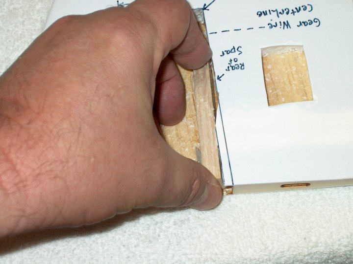
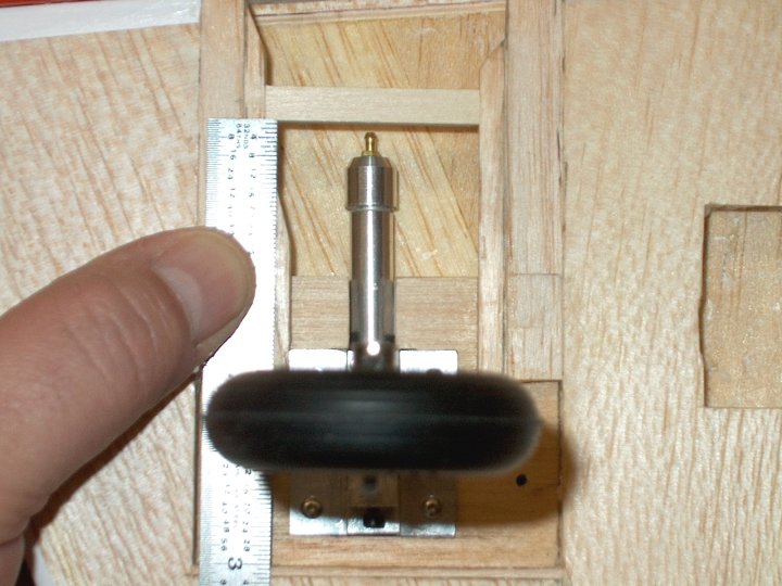
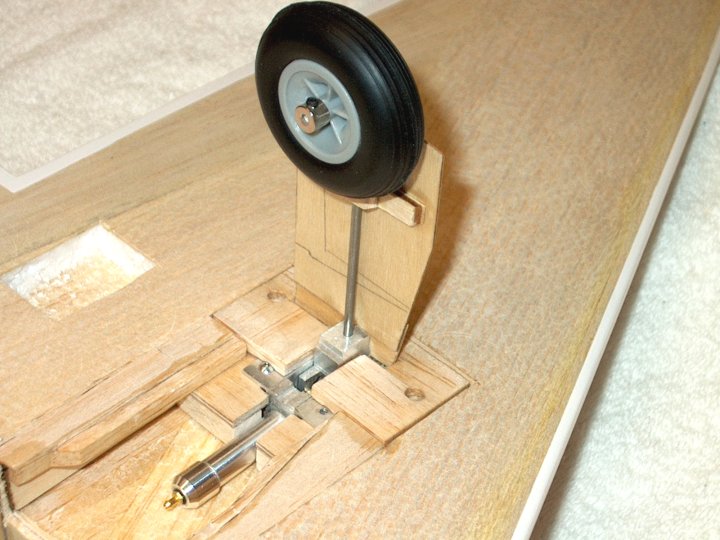
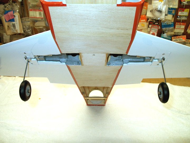
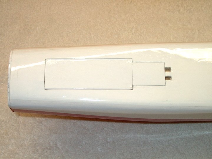
36 - Wing area removed. Note that more
foam was removed later, all the way to the CG line shown on
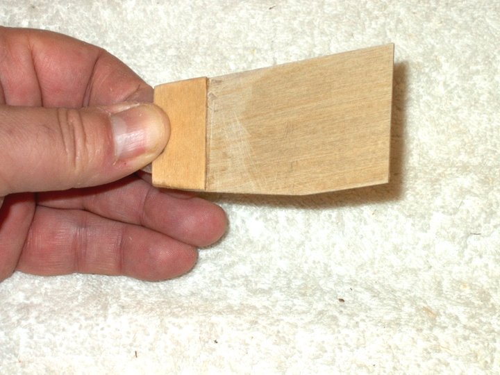
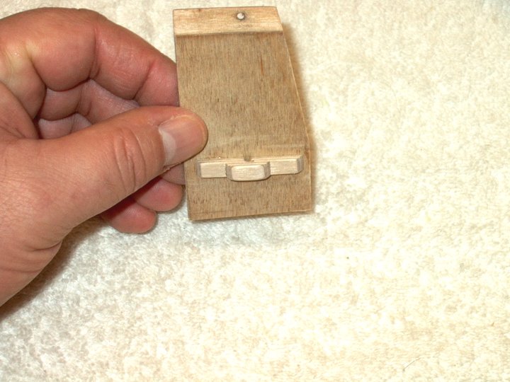
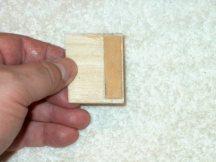
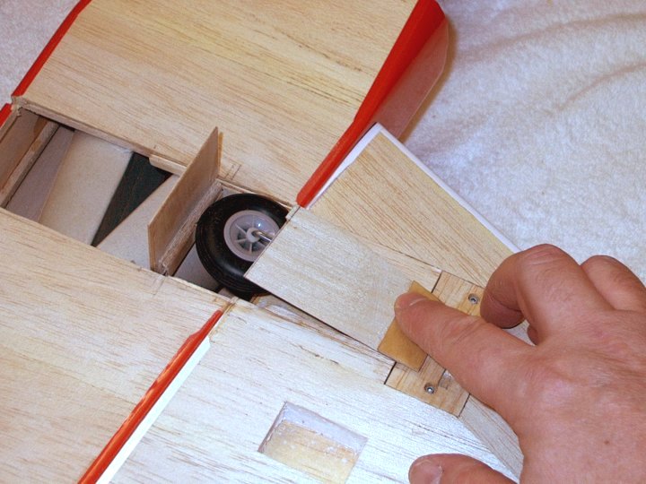
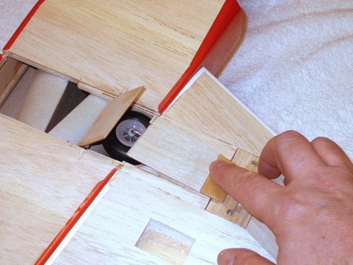
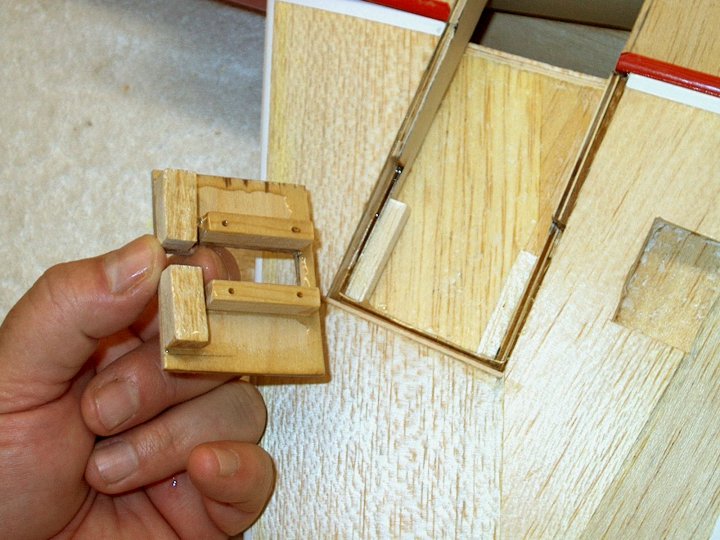
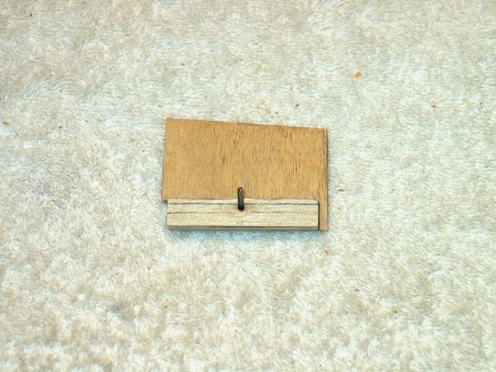
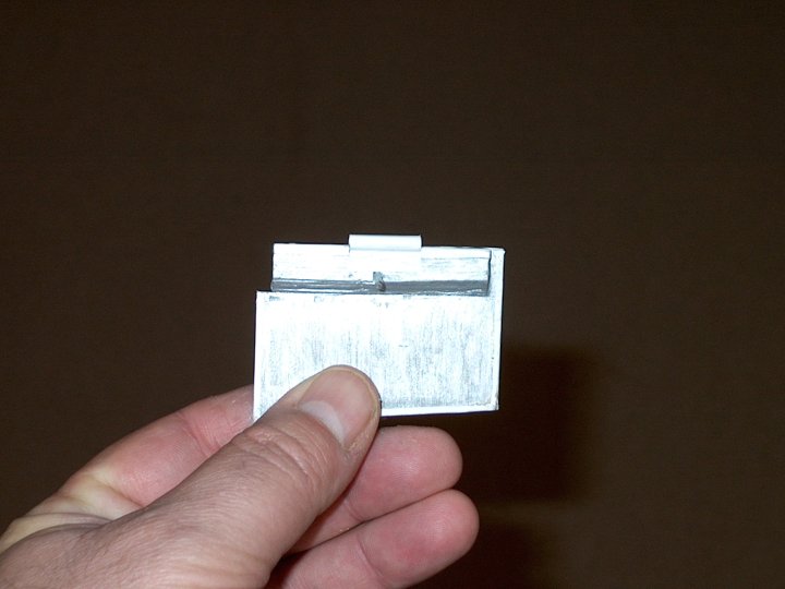
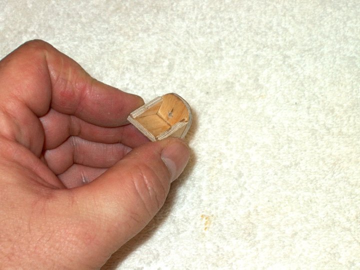
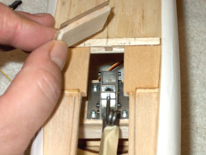
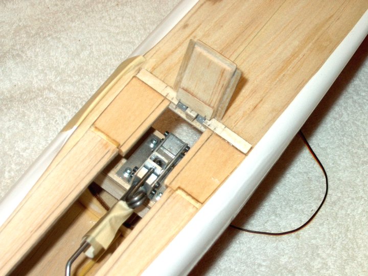
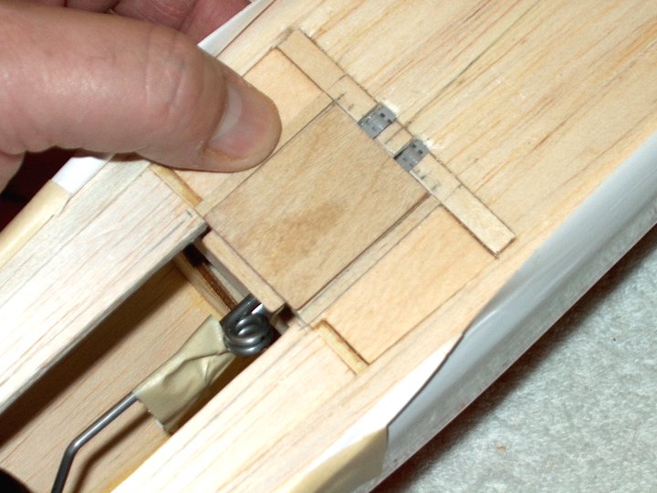
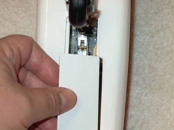
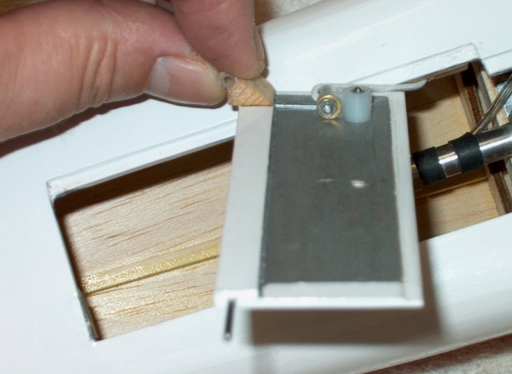
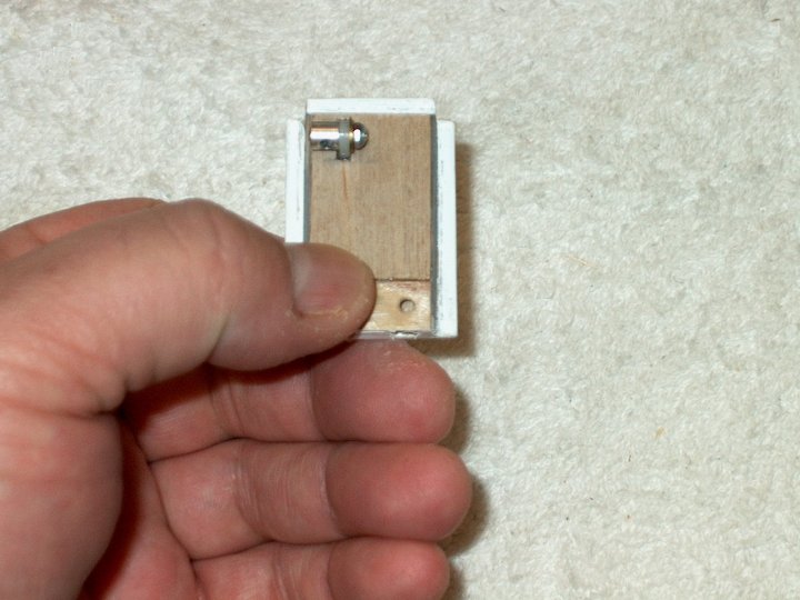
the left. | |
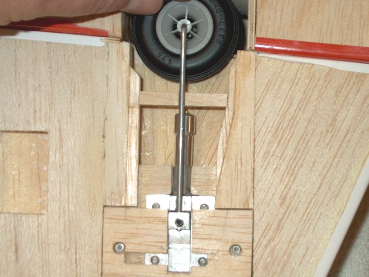
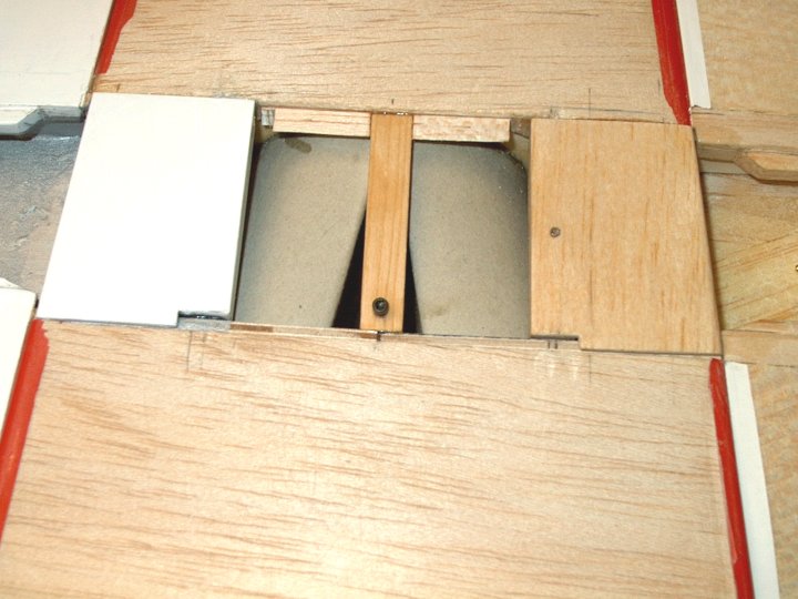
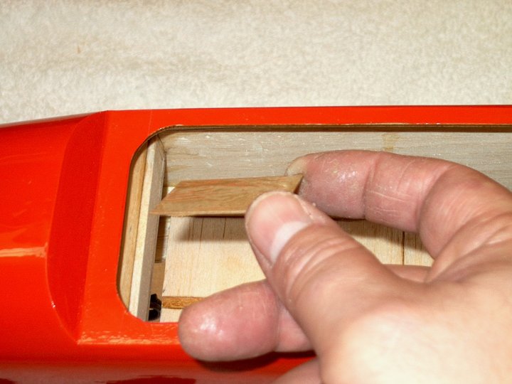
37 - Forward balsa support for the wing
spar was removed. This may take a little cutting to
remove. | |
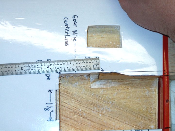
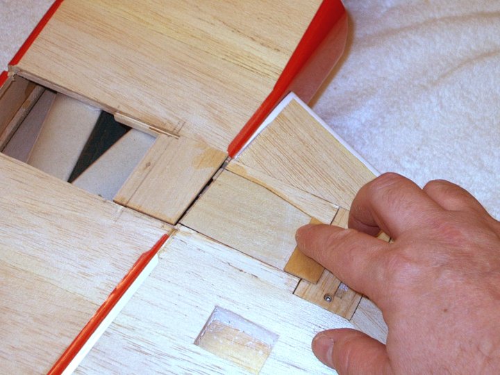
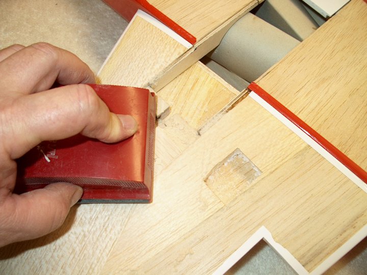
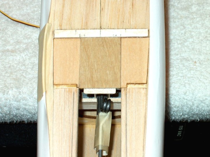
38 - Note that some of the wing sheeting
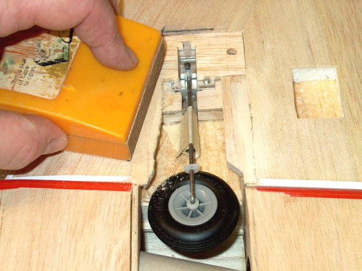
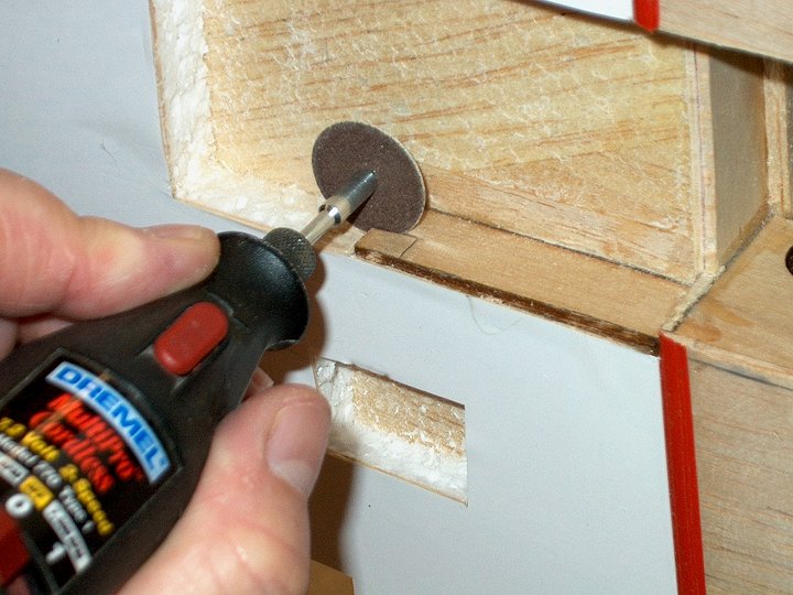
remains to the right of the ruler. This is so the wing spar
has top and bottom sheeting to use when being glued in
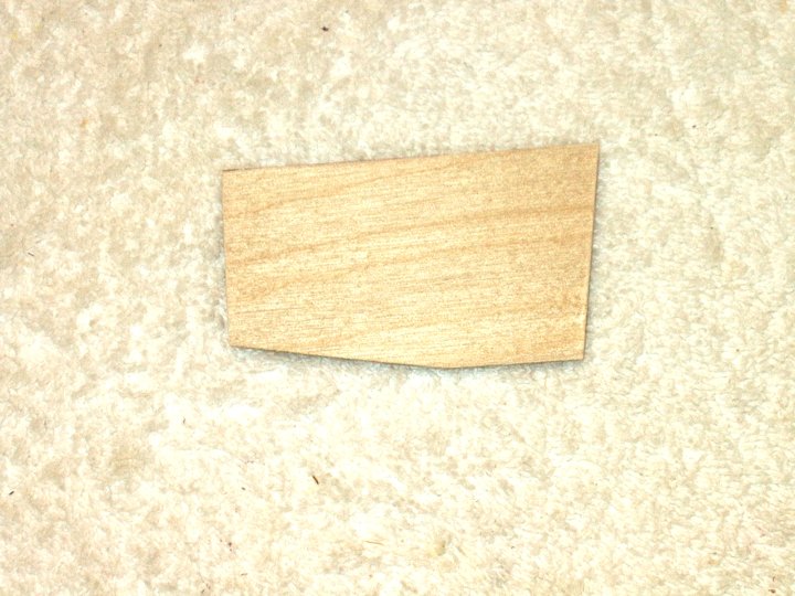
place. | |
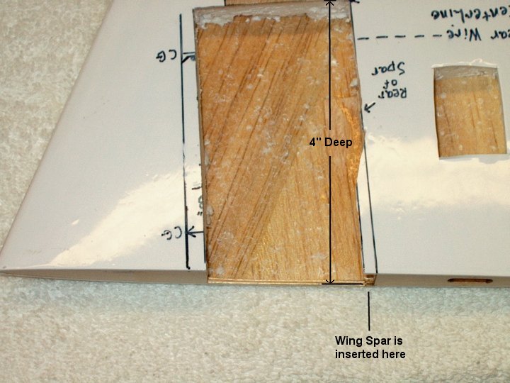
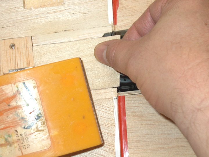
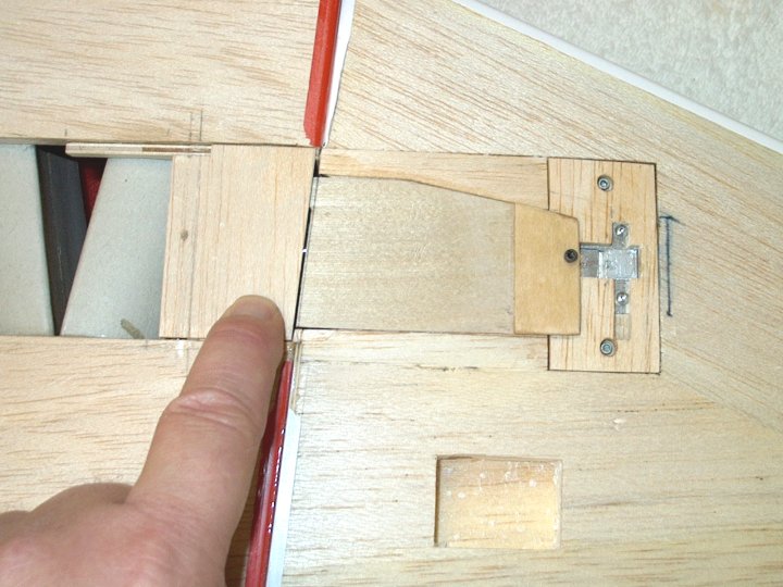
39 - Area cleaned and sanded. Note that
the spar side area is 4" deep. | |
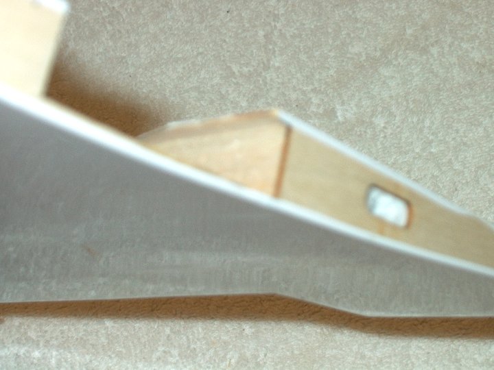
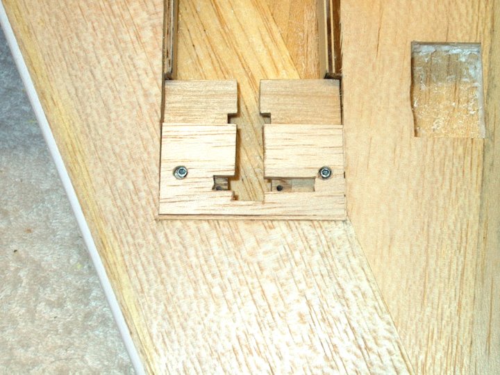
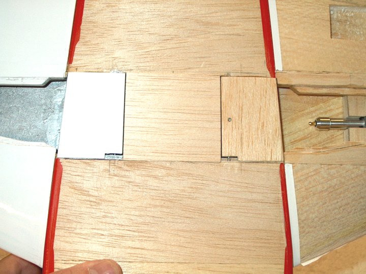
40 - Note the lip / sheeting that still
remains at the top...this is used to keep the main spar
aligned when gluing the wing to the fuselage.
| |
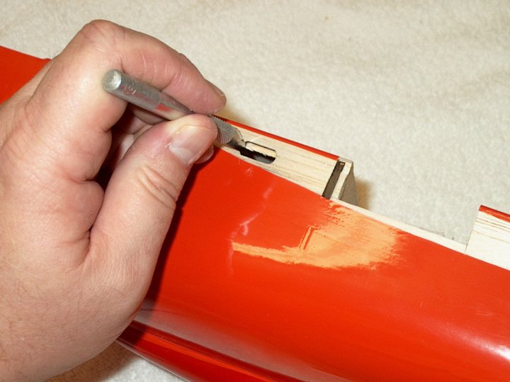
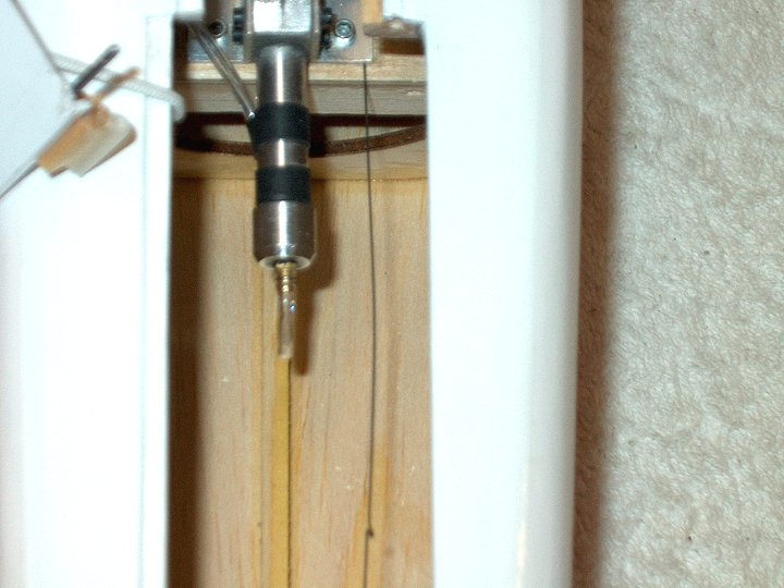
41 - Aileron Servo Wire run cleaned out
with a ruler. | |
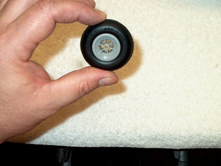
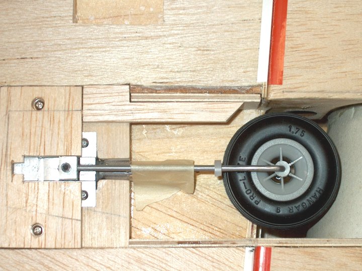
42 - The wheels we used are Hangar-9
Pro-Lite 1 3/4" for the mains and 1 1/2" for the nose wheel.
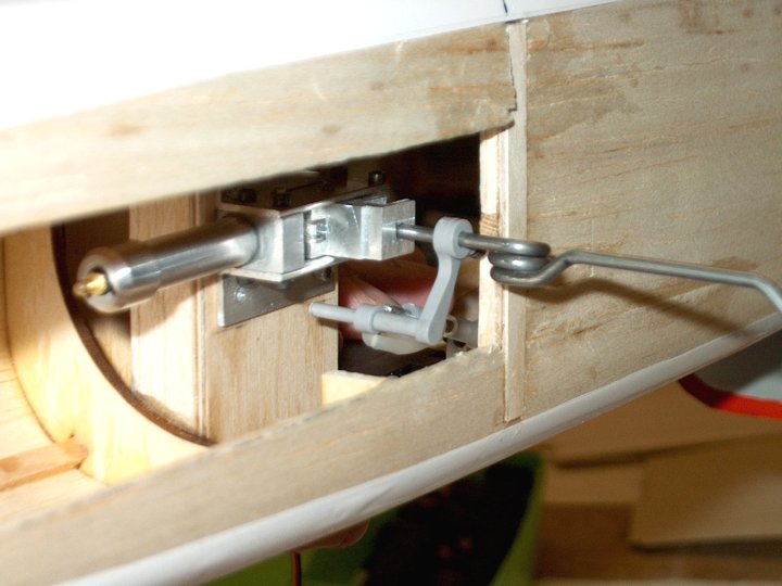
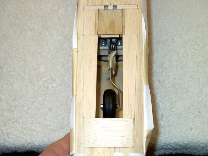
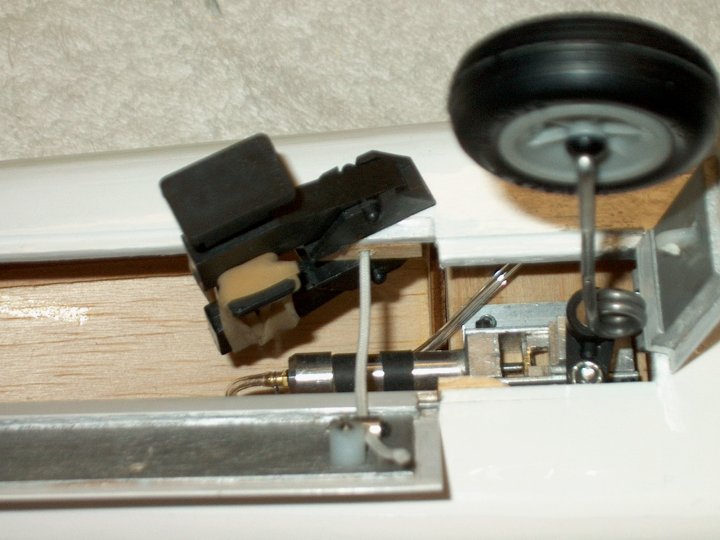
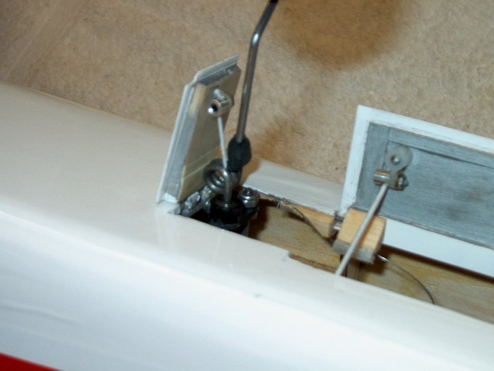
They come with 1/8" shafts, so the next several steps show how
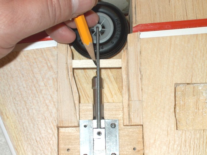
to make a bushing to adapt the 3/32 rod to the 1/8"
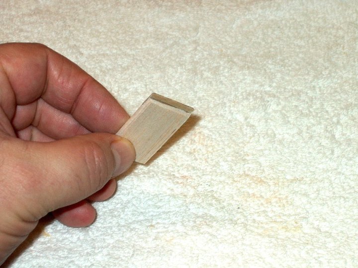
wheel. | |
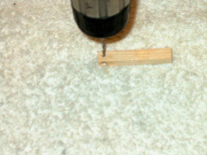
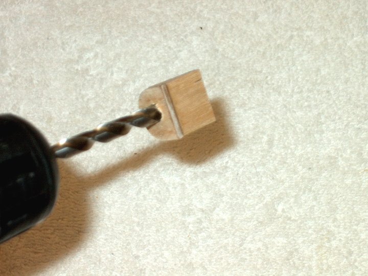
43 - Piece of 4-40 rod inserted into brass
1/8" OD tubing to keep it rigid. | |
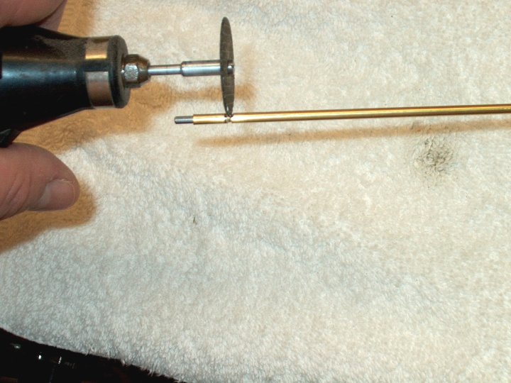
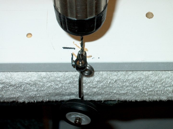
44 - Length of brass tubing cut at
mark. | |
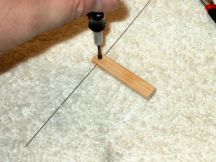
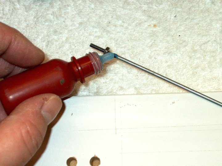
45 - End ground flush.
| |
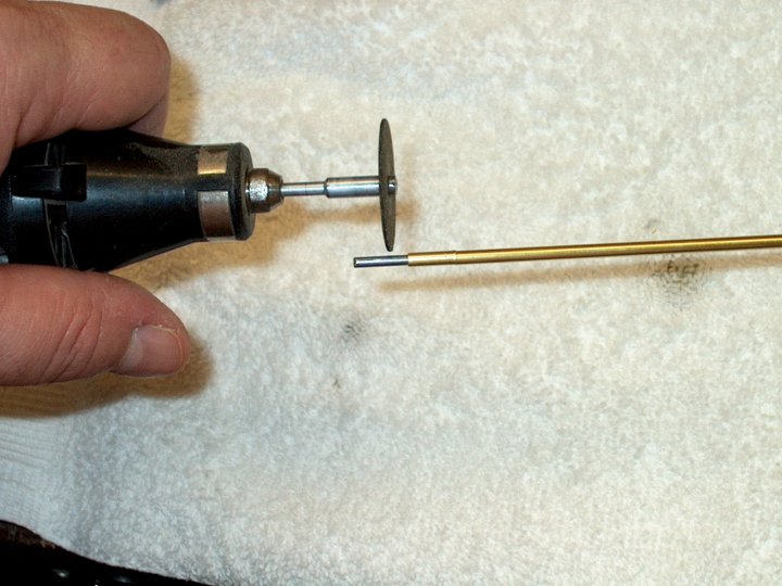
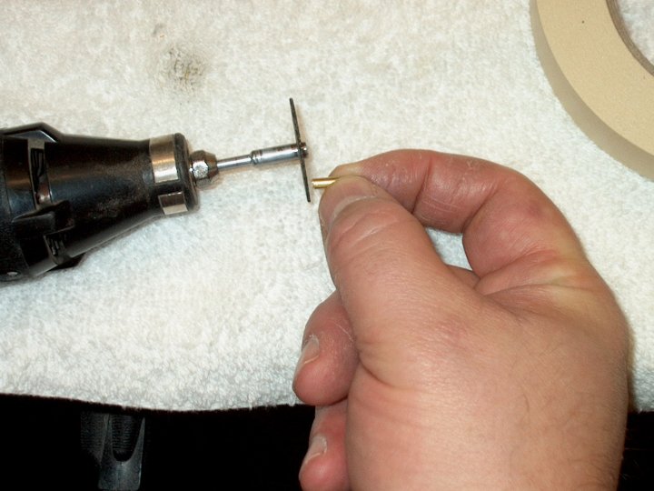
46 - Tubing was placed back on the rod and
the rod was cut to the length of tube.
| |
47 - Edge of small piece is beveled for
easier insertion. | |
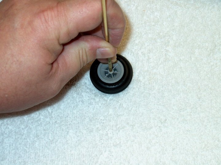
48 - End is placed into the wheel.
| |
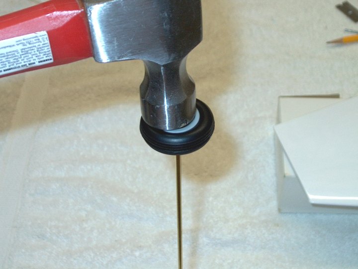
49 - Hammer is used to drive the wheel
over the brass tube. | |
50 - Tube/Rod removed and short piece is
now installed in wheel. | |
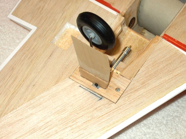
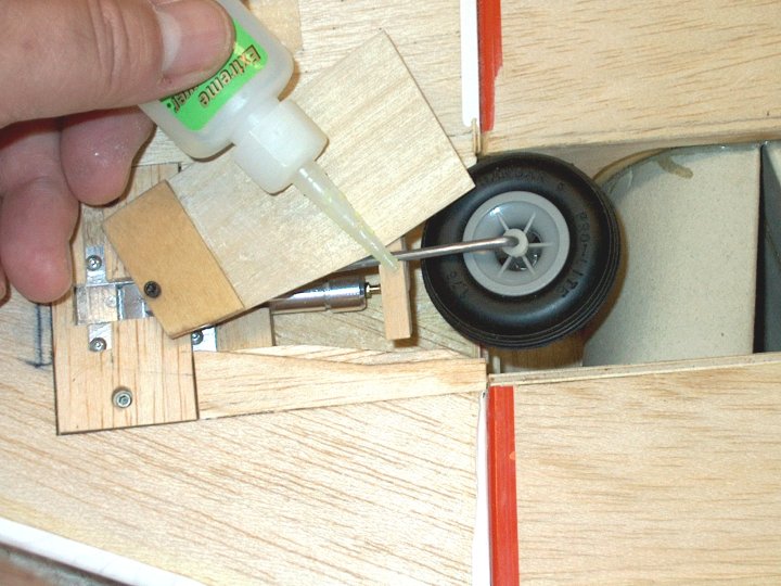
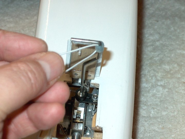
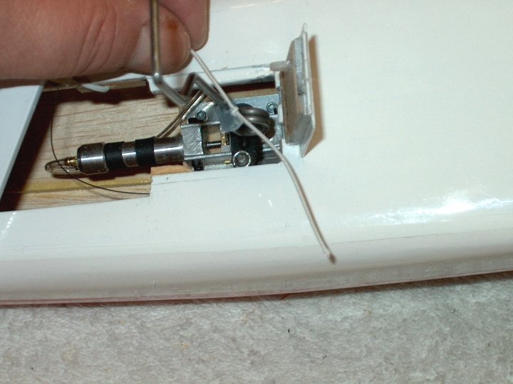
51 - Retract and wheel is place in the
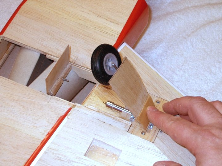
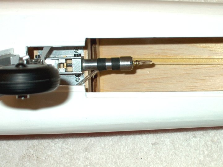
wing to check for clearances | |
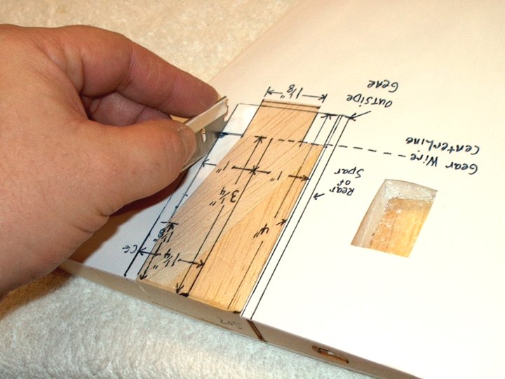
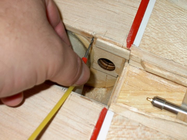
52 - Forward ply wing spar being marked.
Spar Templates will be available and many of these steps show
the development process. | |
53 - Wing being marked at 1mm above bottom
per standard instructions. | |
54 - Spar is epoxied in place and fuselage
root area has epoxied applied. Tape shown at bottom is used to
align wing during installation. | |
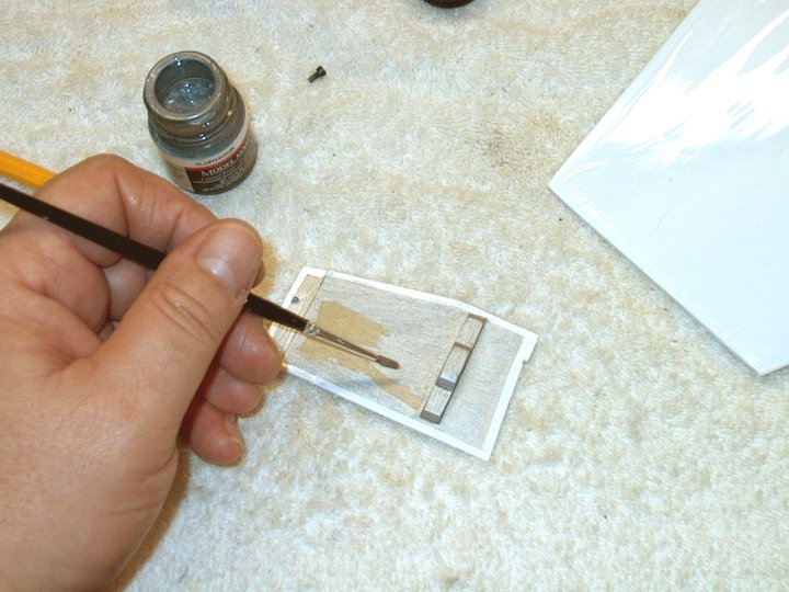
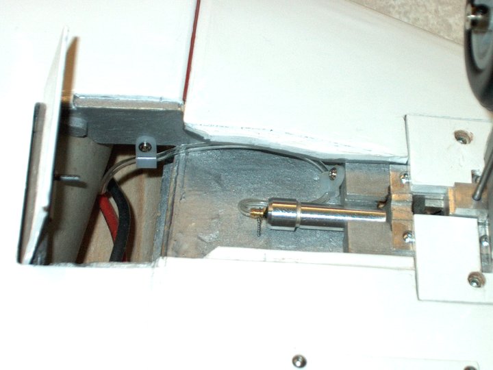
55 - Epoxy is applied to the Spar area.
| |
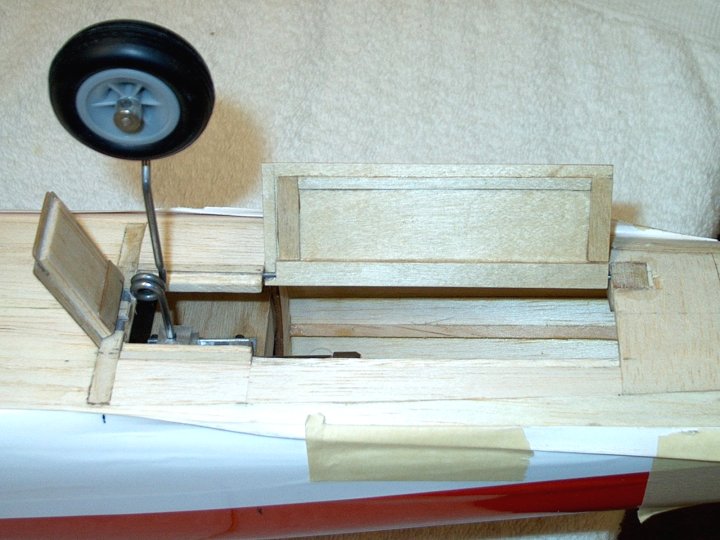
56 - Wing installed against the rear tape,
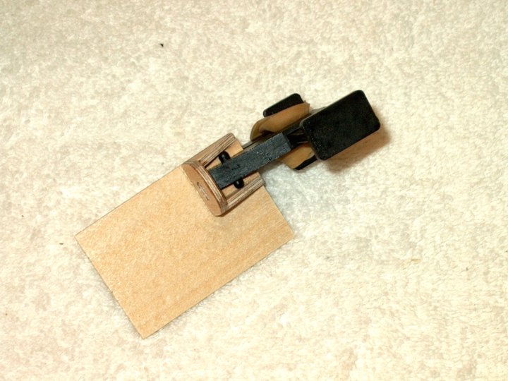
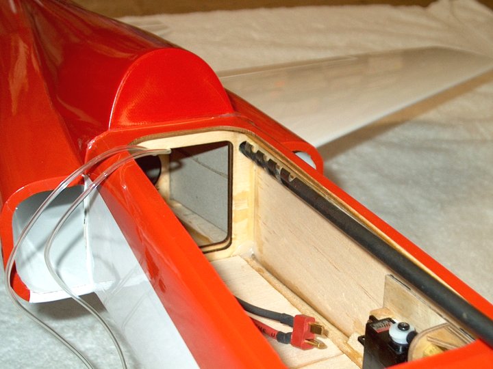
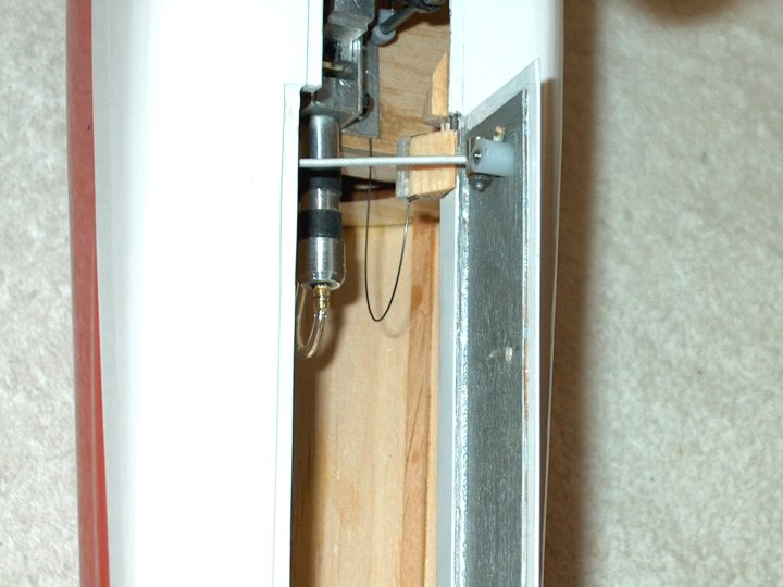
then pinned and tape is removed leaving the rear of the wing
1mm from the bottom. There is a slight dihedral in the
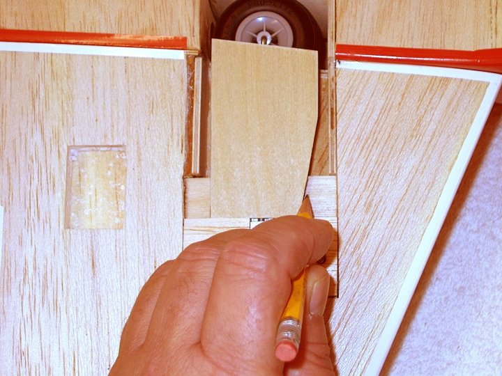
wing. | |
57 - Wing shown with clamp holding spar in
place while epoxy sets. Clean up excess epoxy with denatured
alcohol and paper towels. | |
58 - Wing glued and you can see the Spar
on the left side where it's identified.
| |
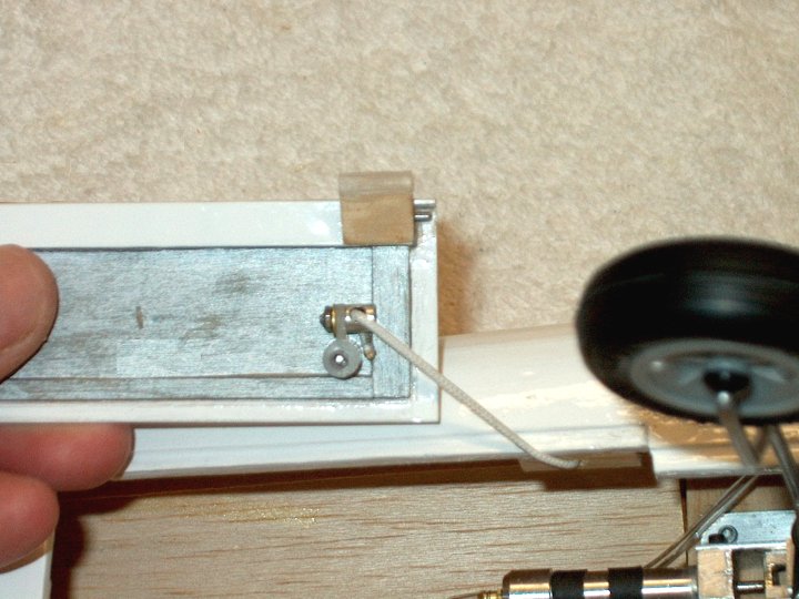
59 - The lip that was left in place to
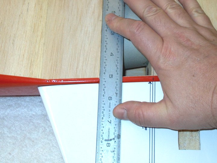
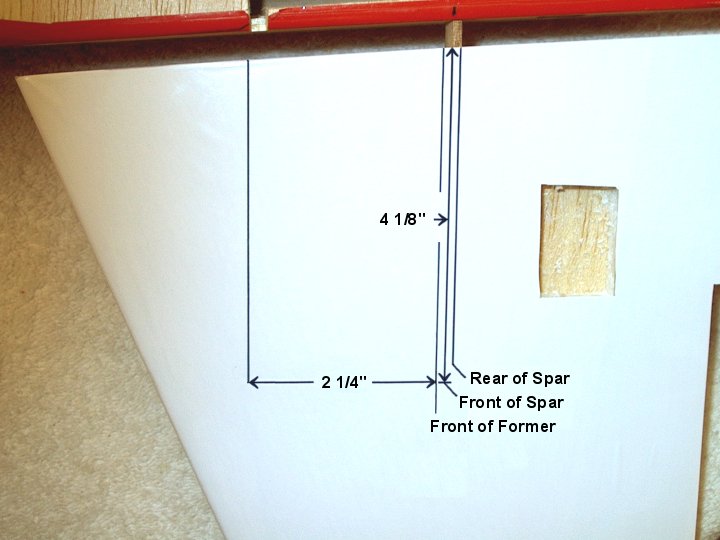
assist with Spar alignment is now removed.
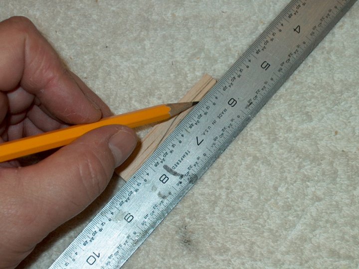
| |
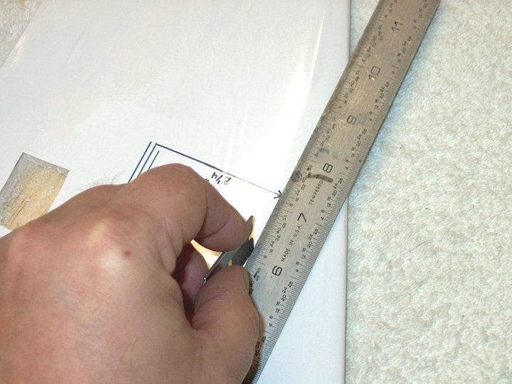
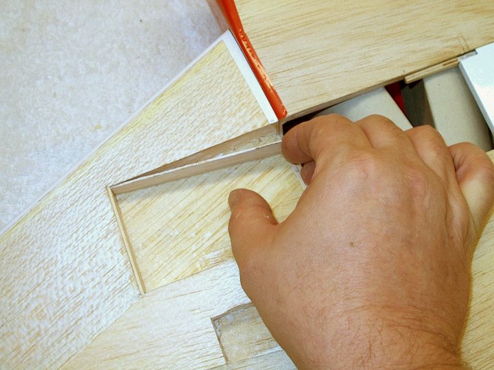
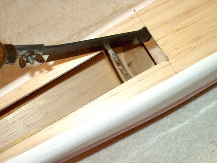
60 - Initial cut is shown for the Forward
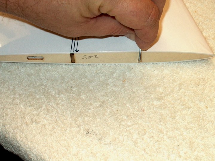
Spar. | |
61 - Forward Spar fit checked to the
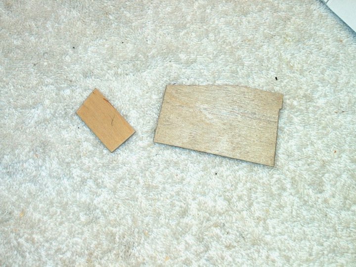
fuselage. | |
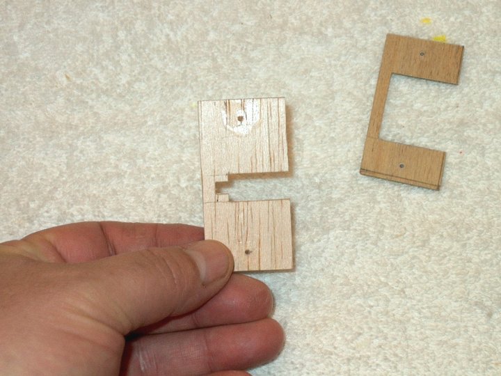
62 - Piece cut to extend the Main
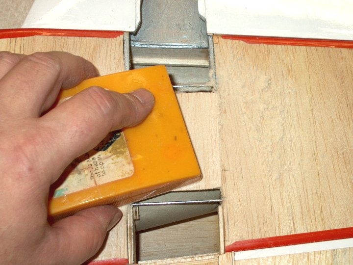
Spar. | |
63 - Ply Main Spar extension shown in
place. | |
64 - Ply end cap is cut and initially
fit. | |
65 - Additional rear spar support
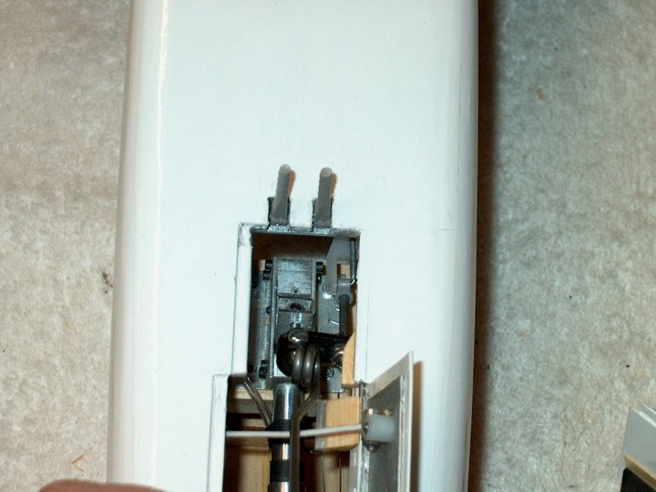
added. | |
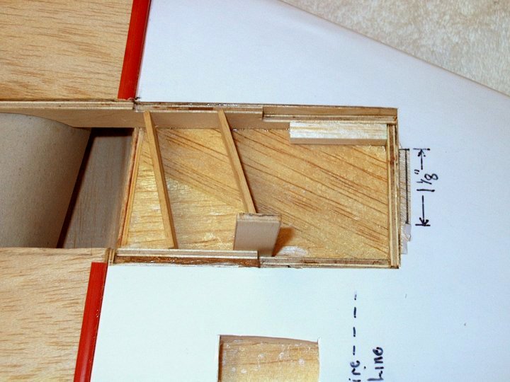
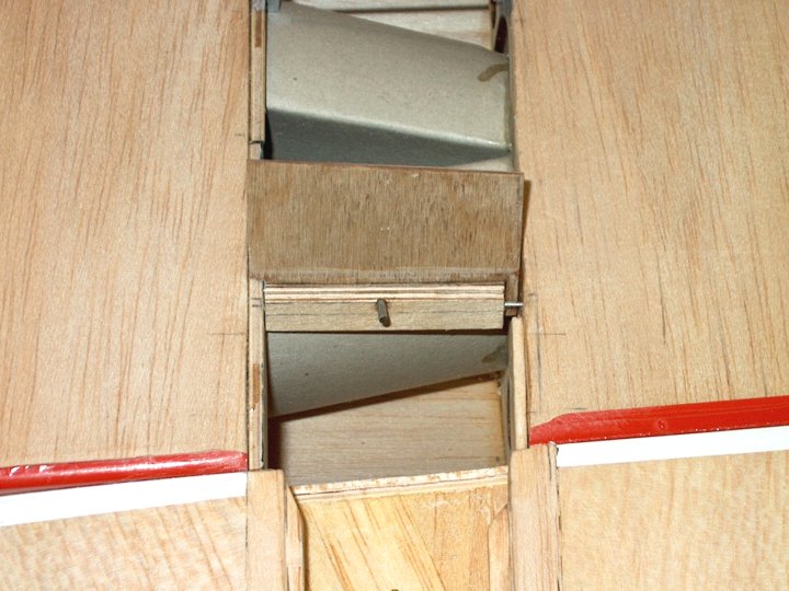
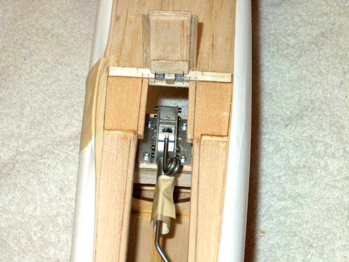
66 - Pic showing retract area boxed
in. | |
67 - Area to the right will be
lowered/shortened so a retract mounting tray can be fit in the
location. | |
68 - Final cuts on spars, shortening them
on the right where the retract tray will be installed.
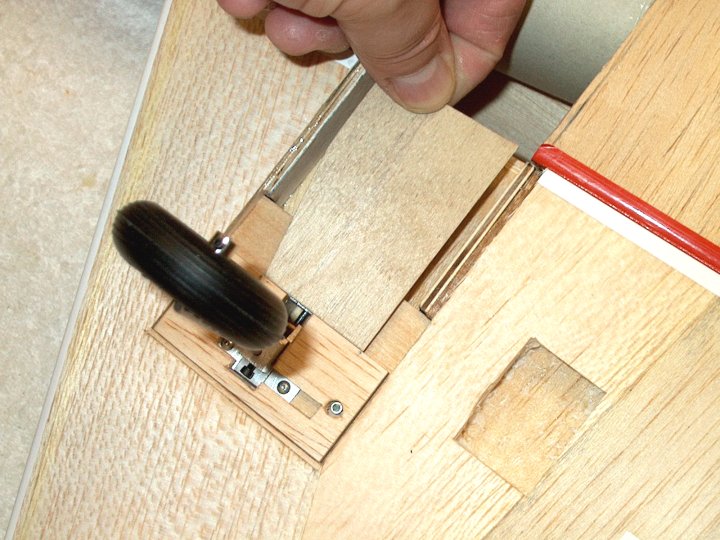
| |
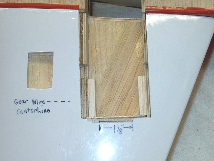
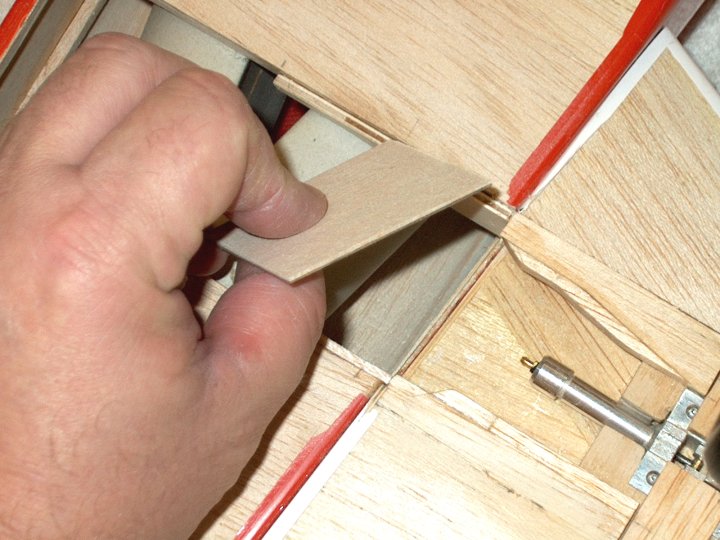
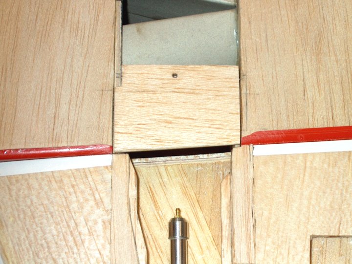
69 - 3/16" x 1/2" piece of balsa was glued
underneath the forward sheeting flush to the edge of the
forward fuselage sheeting. The Forward Spar will attach to
this area. | |
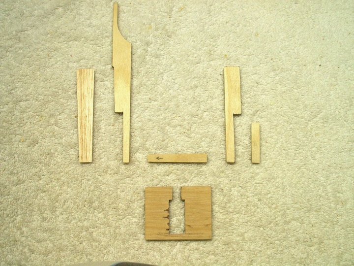
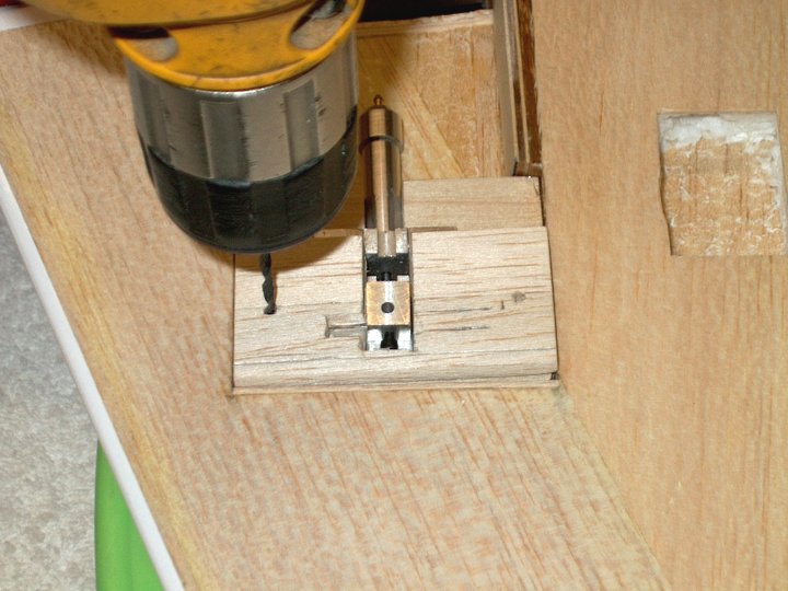
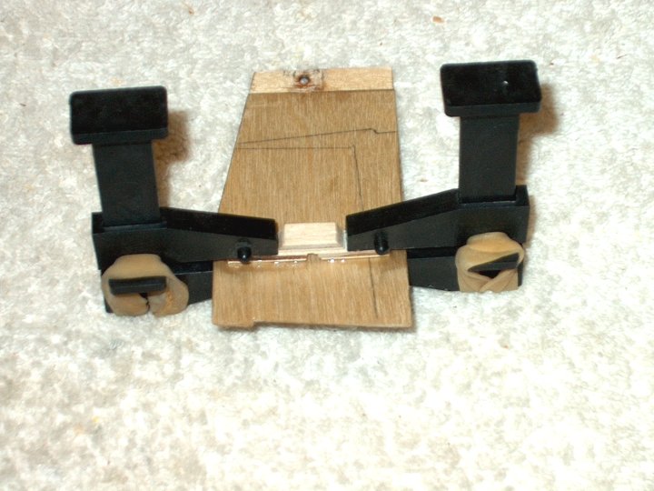
70 - Ply Retract Tray initially
cut. | |
71 - Final fit of all spars shows recessed
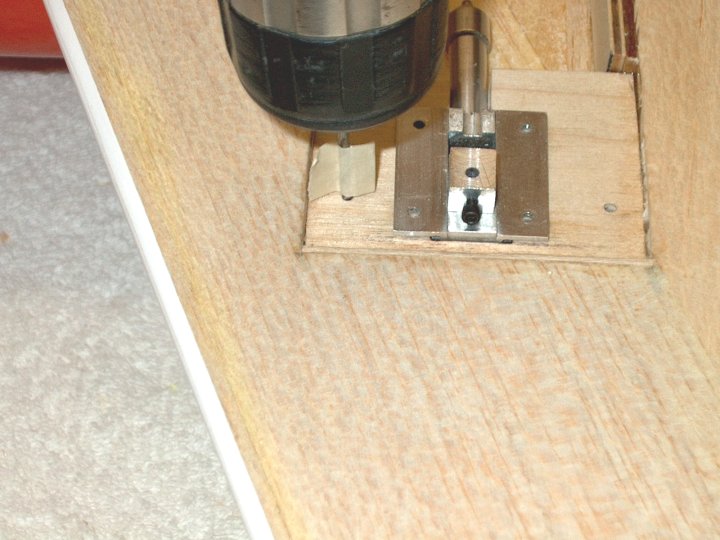
area that was lowered for the tray.
| |
72 - 1/4" wide by 3/8" tall spruce
supports added to bottom of tray for retract screws to bite
into when installed. 3/8" Balsa pieces were fitted forward for
support. | |
73 - Tray is ready to install.
| |
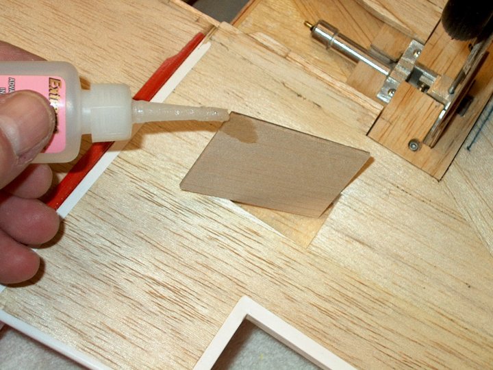
74 - 1/8" balsa plug was installed just
under the lip of the forward wing sheeting so the Forward Spar
has something of substance to adhere other than foam. Scrap
pieces of balsa were used to wedge the piece in place until
the epoxy set. | |
75 - Plug shown installed.
| |
76 - Forward Spar shown with epoxy
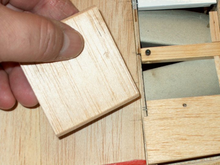
applied. | |
77 - Spar is held in place with scrap
balsa used to "wedge" it in place. Note the 1/4" balsa square
added top right to support the corner and give the retract
plate more surface to adhere. | |
78 - Spars glued in place and ready for
the retract tray. Two 1/4" balsa supports added flush to the
top of the spars for support. | |
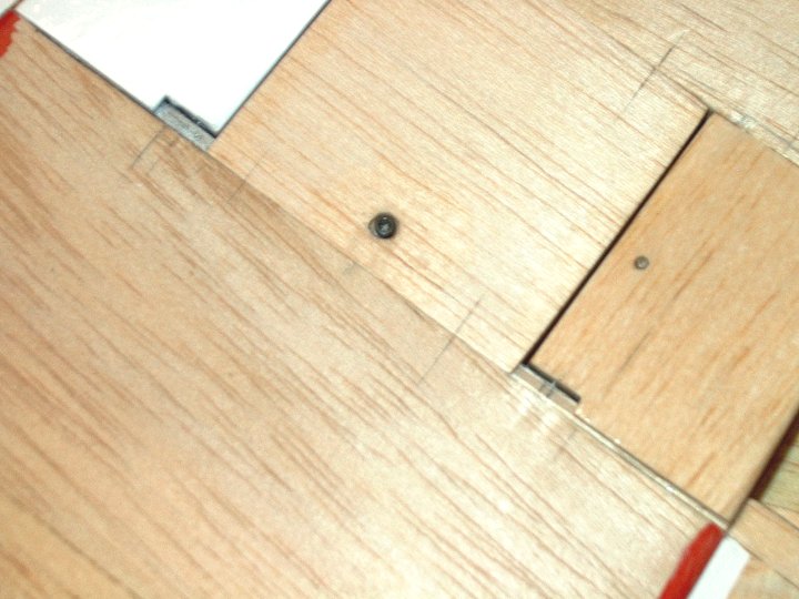
79 - Dry fit the tray before gluing.
|
|
80 - Epoxy is applied to tray and wing
area. |
|
81 - Tray installed into wing.
| |
82 - Full view of tray area.
| |
83 - Retract installed and holes marked
for screws. | |
84 - Holes drilled with 1/16" bit. Tape
was used on the bit to mark depth so you don't go through the
top of the wing. | |
85 - Screws were run in holes to make
threads, then the holes were reinforced with thin CA.
| |
86 - Retract installed with Great Planes
#2 x 1/2" Button Head Screws. | |
87 - Retract is shown installed.
| |
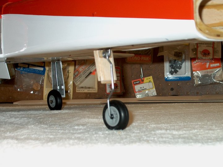
88 - Photo showing gear installed in "Gear
Down" position. | |
89 - Photo showing gear installed in "Gear
Up" position, with about 1/8" clearance in the front and back
for the tire. | |
90 - A Retract Cover is made from a 1/32"
ply base on the right and covered by a piece of 3/16" balsa
shown in the middle. The ply piece is cut to fit around the
retract, while the balsa is cut to only expose the moving
part. | |
91 - Ply base for the retract cover put in
place this base will allow reset screws to be used for
mounting. | |
92 - Balsa Retract Cover top piece set in
place over the ply lower cover. | |
93 - Balsa and ply plate trial fitted and
drilled through retract plate. | |
94 - 3/16" holes for the entire screw head
to sit recessed are drilled in balsa plate only! The ply and
balsa are glued together with medium CA, then screws are
inserted through the holes into the lower ply plate and the
assembly is tightened. | |
95 - Covering was removed and 100 grit
sandpaper was used to properly shape the Retract Cover so it
sits flush with the wing. | |
96 - Retract Cover completed.
| |
97 - Retract Door was made from initial
template from 1/32" plywood. Note the grain orientation in
this photo and all that follow. | |
98 - The Retract Door was temporarily set
in place, evenly spacing it between the two plywood spars and
its location was marked. | |
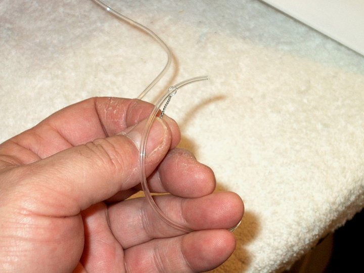
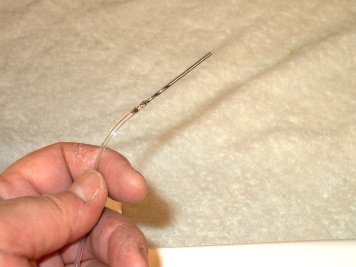
99 - Pencil Marks show Door
location. | |
100 - Pieces of 3/16" balsa were cut and
fitted to each side of the bay, then glued in place. The top
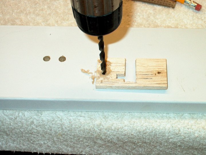
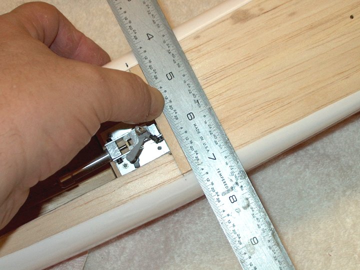
of the balsa is flush with the spar and there is a 3/16"
overhang for the door to rest on when closed.
| |
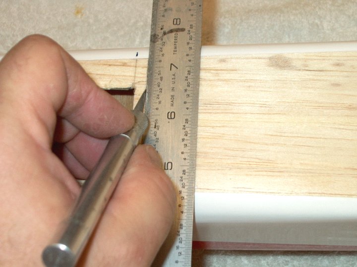
101 - 3/32" balsa was glued along the door
line on both sides, then sanded flush to the wing.
| |
102 - Balsa shown fitting flush to the
door with a small gap on each side to allow for the
covering. | |
103 - Door shown in place with sanding
completed. | |
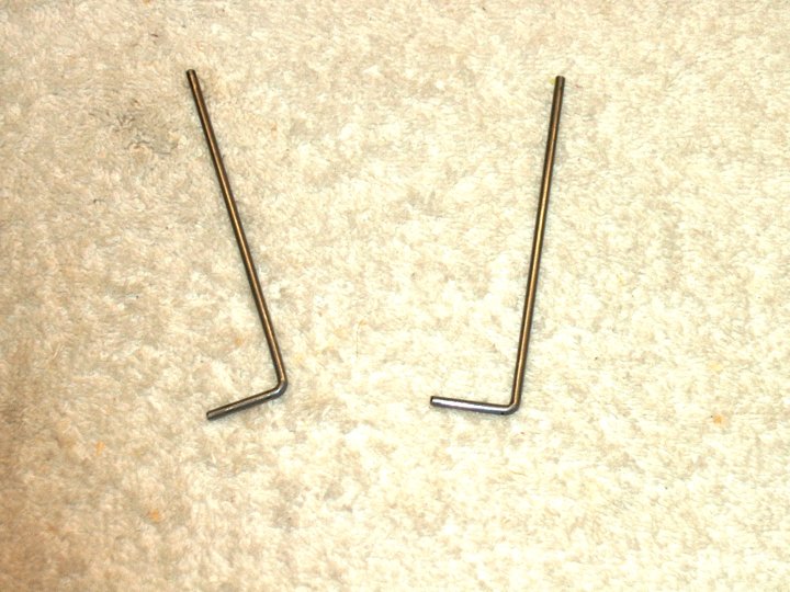
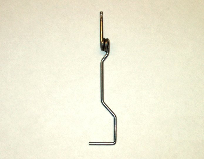
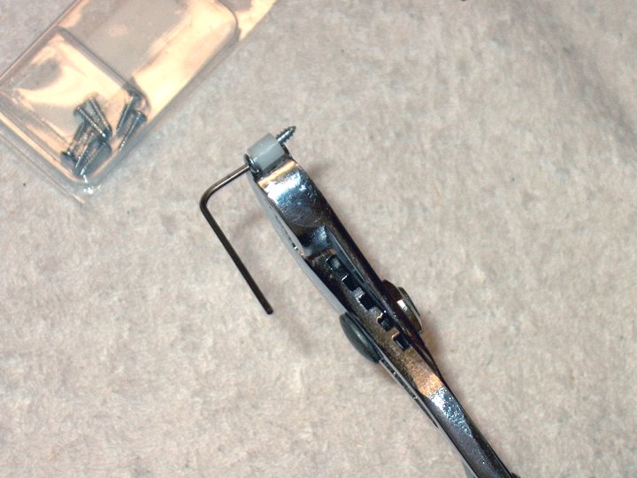
104 - A piece of 1/16" Ply with grain
shown running top to bottom was cut 3/4" wide and half of it
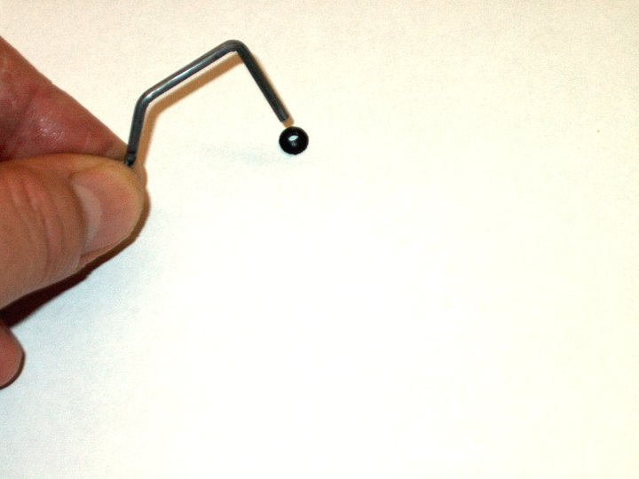
was glued to the door, then shaped to contour.
| |
105 - Back side showing 3/8" overhang on
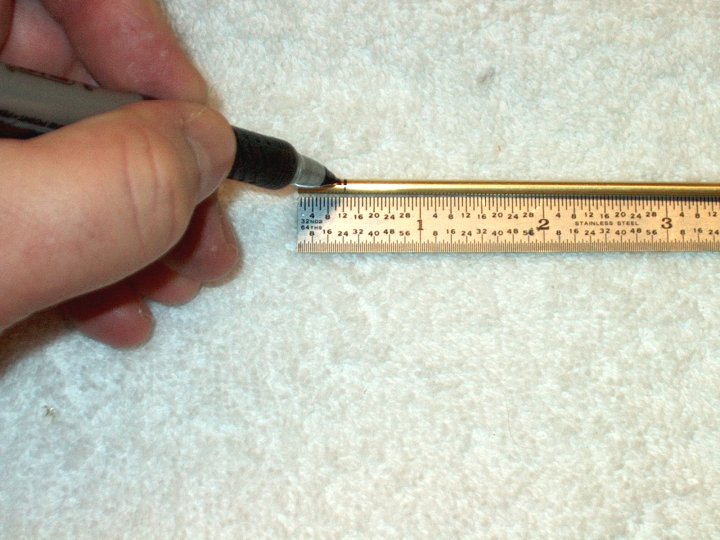
ply plate. CA was added for drilling to prevent
splintering. | |
106 - The piece was laid over its position
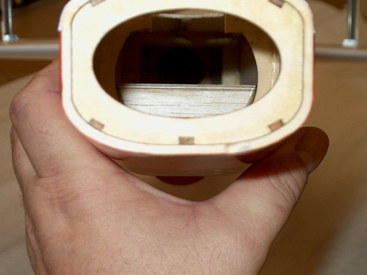
and the hole was marked , then drilled. The bolt for the
landing gear wire is used to hold the door in place.
| |
107 - Hole drilled and CA added.
| |
108 - Retract Door shown installed using
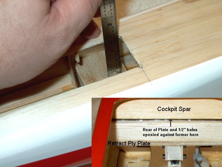
the bolt for the wire gear. Note the area to the left on the
Retract Cover that was cut out for the door so the retract
could lock in place. | |
109 - Retract extended and locked in
place, showing why the area under the door needed to be
removed. | |
110 - A piece of 1/8" ply 1/4" wide was
cut, the ends were beveled, then it was set in place as shown.
Make sure it is 1/8" above the wheel so it doesn't rub. A
pencil marks the gear location. | |
111 - a second piece of 1/8" ply 1/2" long
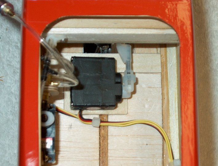
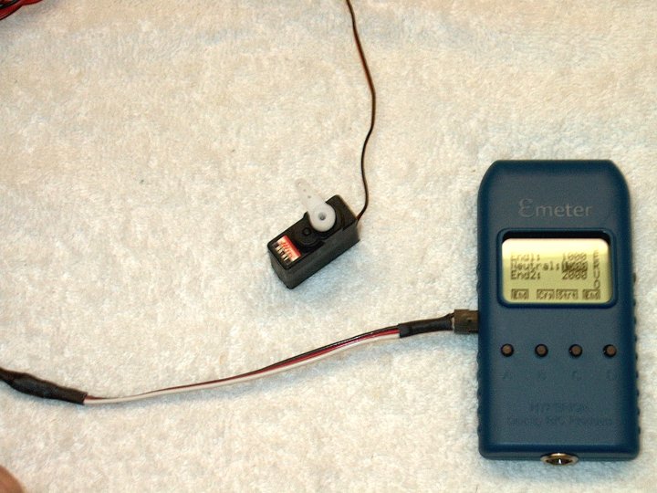
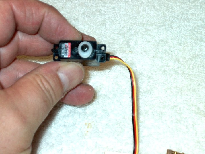
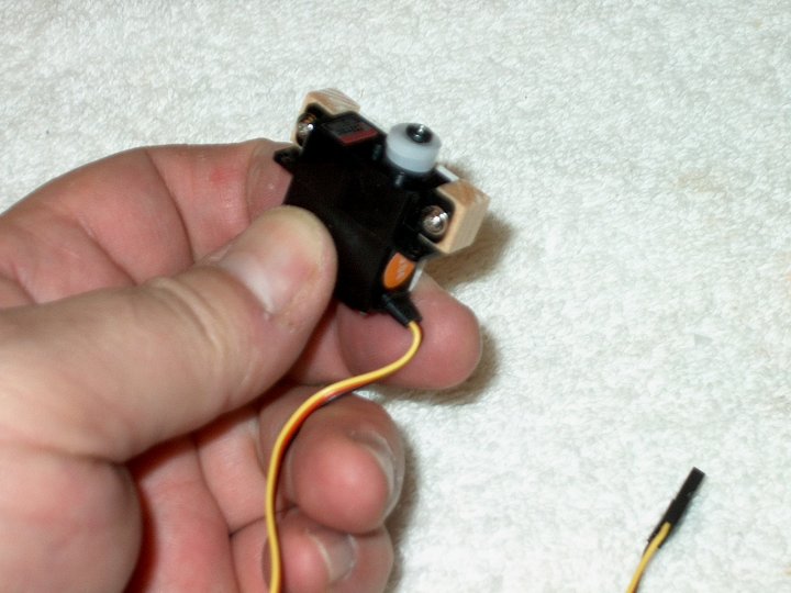
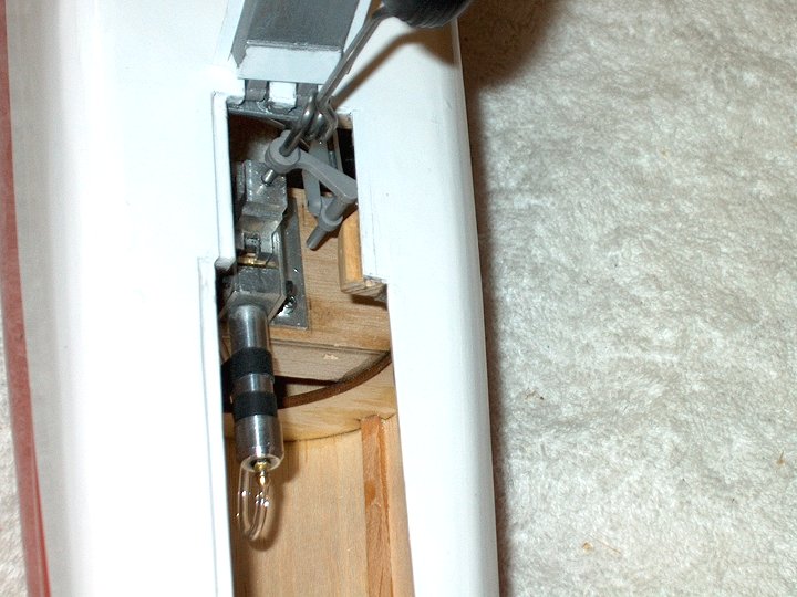
was beveled and glued to the center.
| |
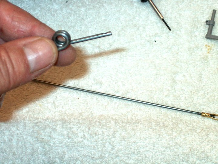
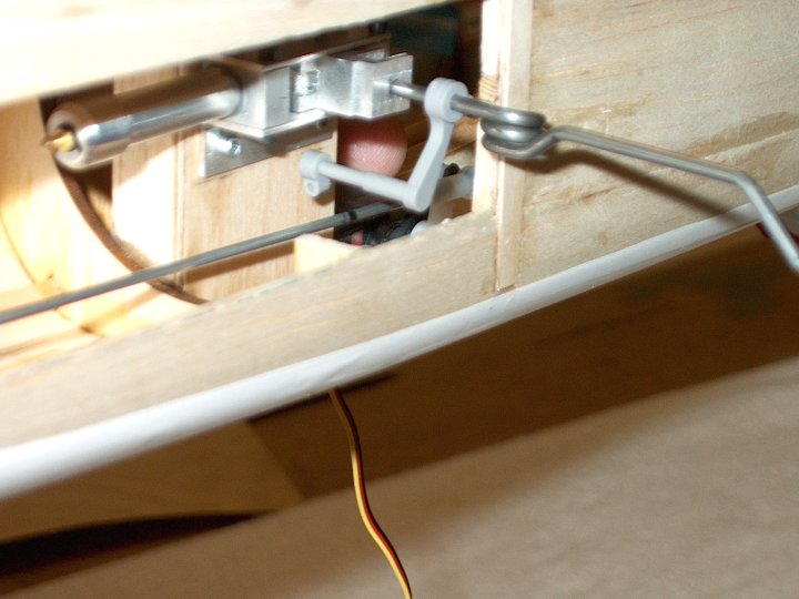
112 - The ply brace was cut out to clear
the landing gear wire. | |
113 - Brace was then pushed over the
wire. | |
114 - Brace test fit. The ends are beveled
to help with alignment, making sure the door closes
straight. | |
115 - A rule is used across the back spar
in the fuselage to make sure the wheel is parallel to the
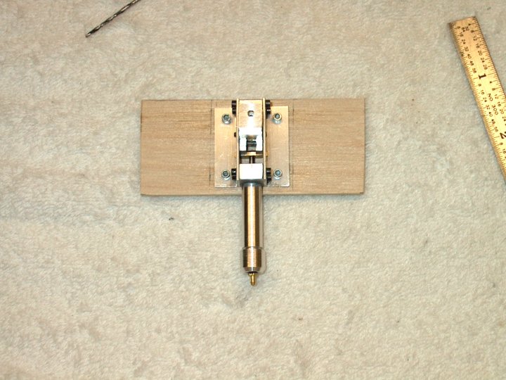
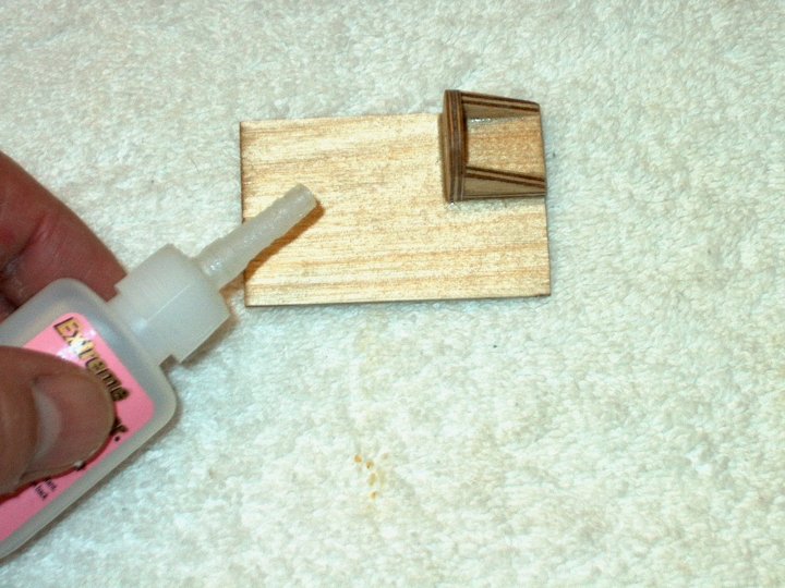
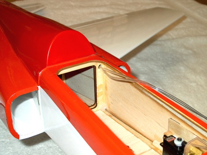
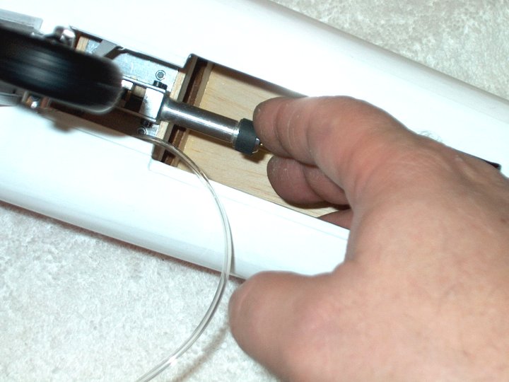
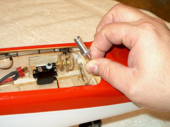
fuselage centerline. | |
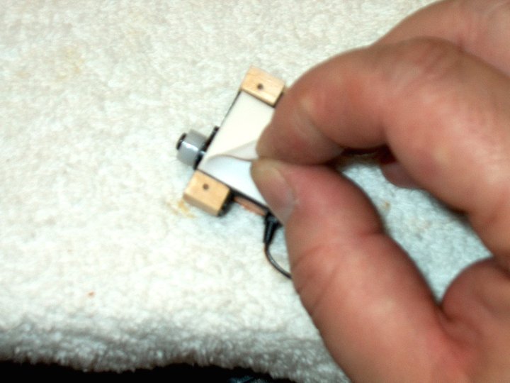
116 - CA is added to the brace, then the
door is swung in place. IMPORTANT! Note the 1/8" clearance
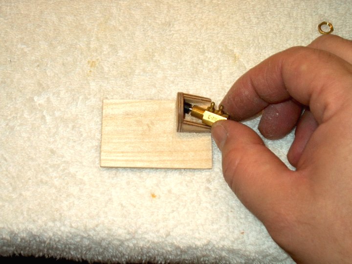
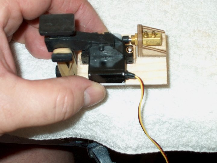
between the brace and the top of the wheel; make sure you
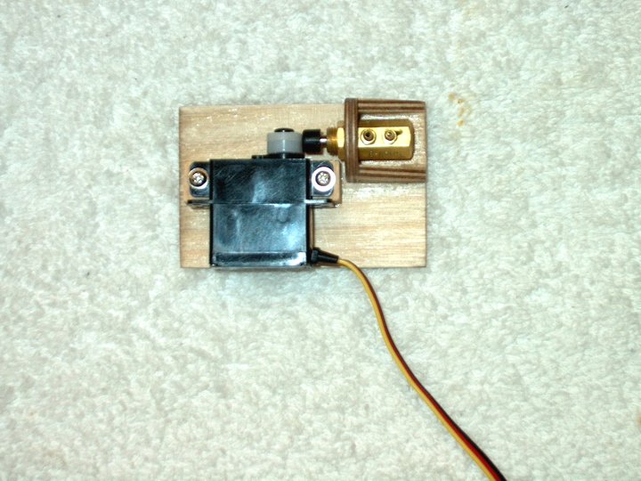
space it like this so there is no rubbing.
| |
117 - Retract Door with Brace
installed. | |
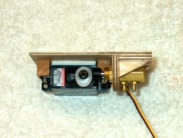
118 - Fuselage door cut from 1/32" ply and
3/32" balsa, then laminated. Note that the ply grain is cross
while the balsa grain is vertical. Crossing grains like this
is important for strength. | |
119 - A piece of balsa 1/8" thick by 3/8"
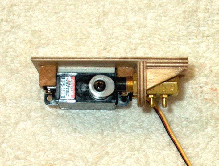
wide by 1" long is installed with the top recessed and even
with the rear ply spar plate. | |
120 - The Fuselage Door is tack glued in
place, then sanded until it is flush with the fuselage.
| |
121 - Door is "popped" out from its tack
spot. | |
122 - Edges of the door are sealed and
strengthened with thin CA. | |
123 - Door is set in place and checked for
clearance. Marks are made where the top of the wheel is
located. | |
124 - A piece of 1/16" ply 1/2" wide is
glued to the inside ply of the door. The center of the ply is
1/8" to the right of the wheel edge previously
measured. | |
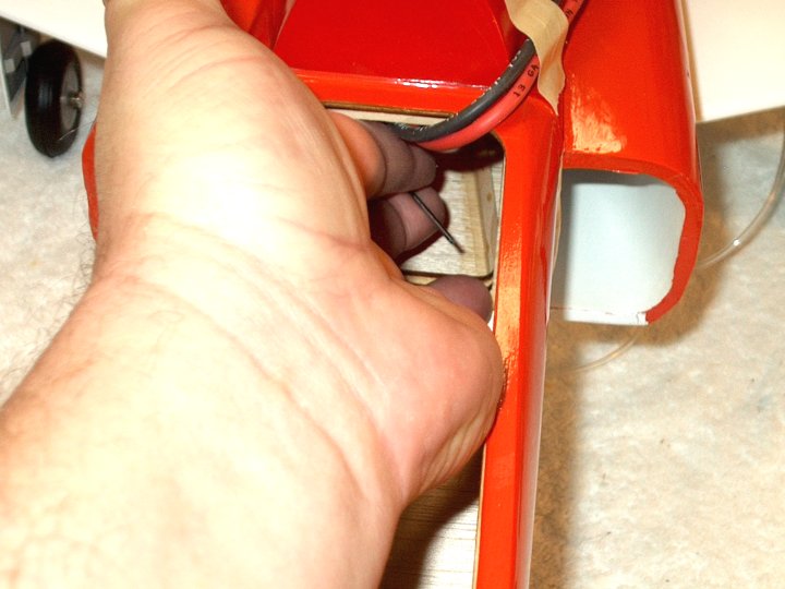
125 - A piece of micro pushrod wire is
installed in the fuselage at the second mark (left) which is
1/8" beyond the first marker (top of wheel). Wire holes were
drilled 1/16" below the top of the ply spars.
| |
126 - 1/16" thick by 1/4" wide strips of
ply were cut and glued in place with the wire running down the
center. Note the door has been notched on the right to clear
the ply spar when opening. | |
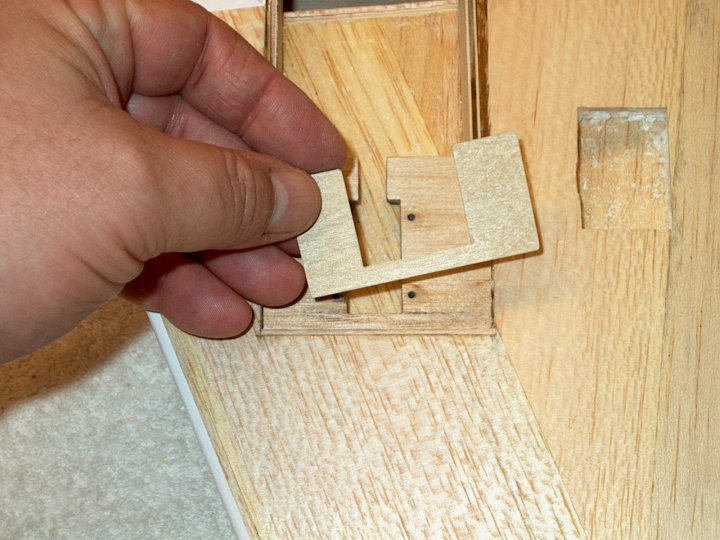
127 - A 1/32" ply cap was glued to retain
the wire on the left. | |
128 - A hole was drilled and a piece of
2-56 rod was glued in place, protruding about 3/8". Pliers are
used to fine tune the wire by bending it until the door closes
without binding. | |
129 - Retract Door Assembly shown fully
opened. | |
130 - Retract Door Assembly
closing. | |
131 - Retract Door Assembly wheel contacts
2-56 rod. | |
132 - Retract Door Assembly wheel pushes
rod downward closing the door. | |
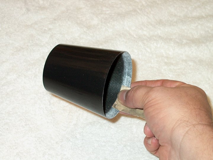
133 - Retract Door Assembly Fuselage Door
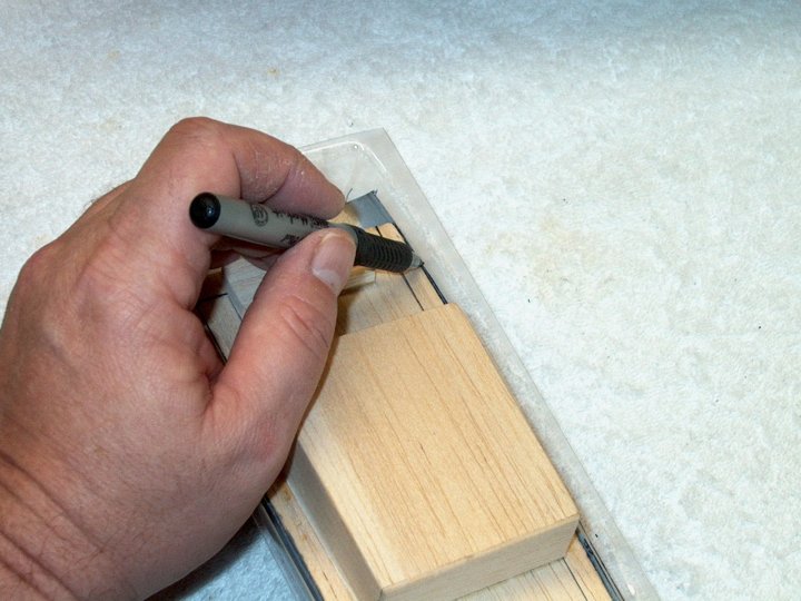
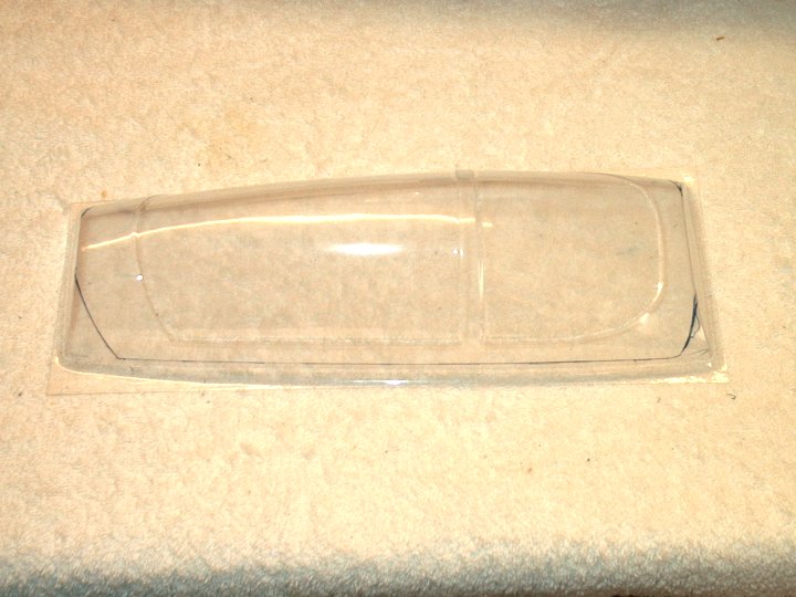
and Retract Door closed. | |
134 - Top view showing clearances and fit
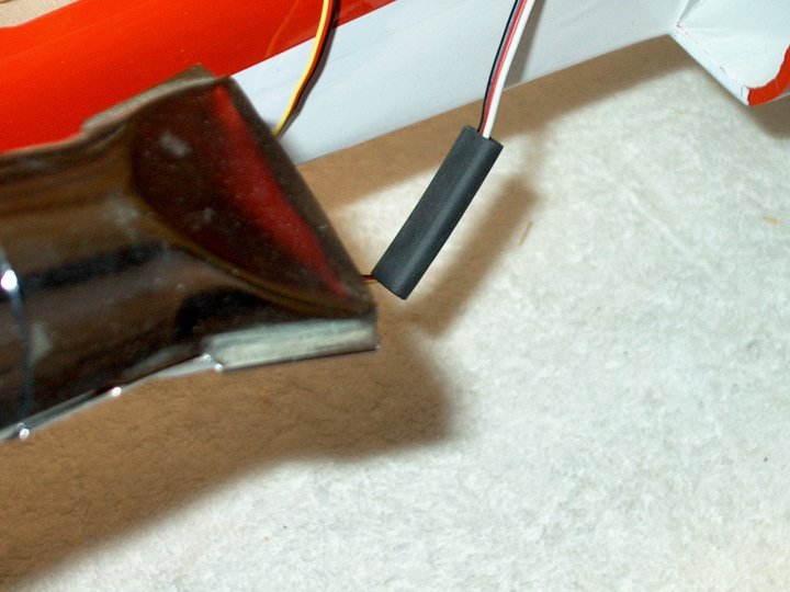
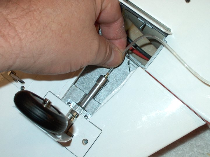
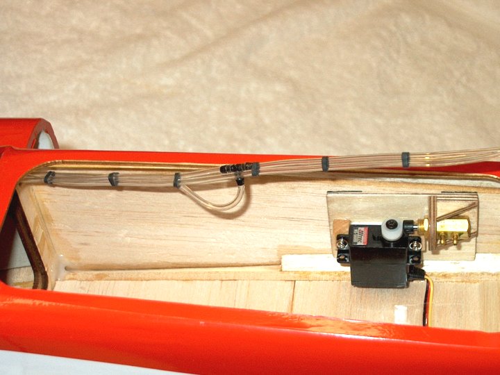
with doors closed. | |
135 - Fuselage Door Stop cut from 1/8"
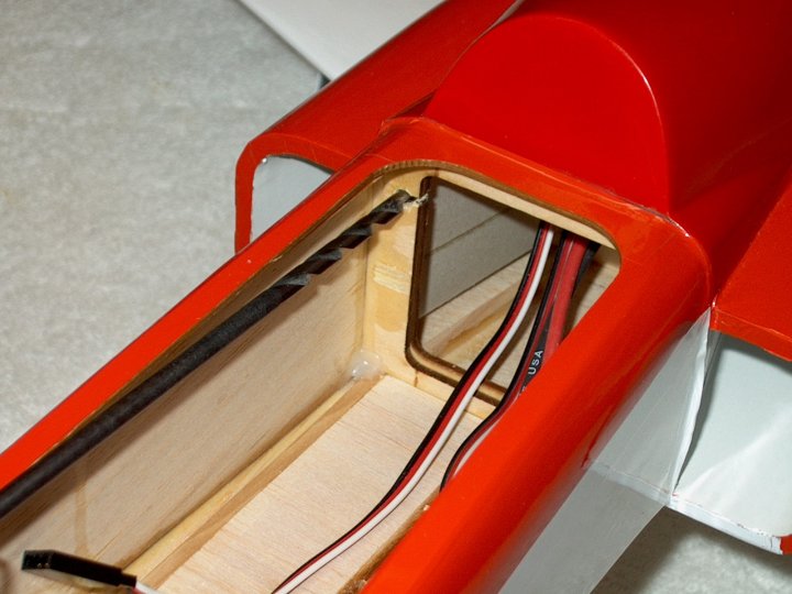
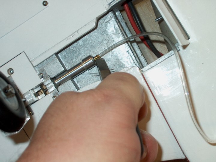
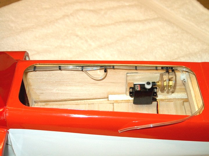
ply. | |
136 - Wing Door semi closed and Fuselage
door is checked for clearance. The inner door (left) was
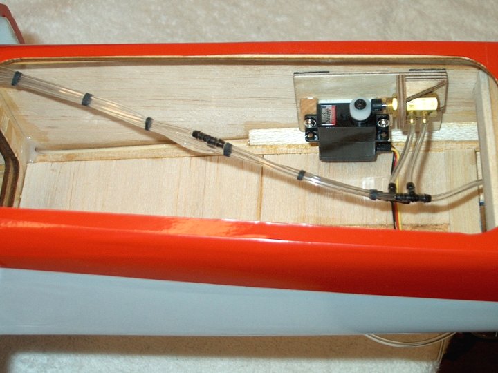
adjusted for around 1/4" clearance to the wheel.
| |
137 - While the inner Fuselage Door is
held at the angle, the door stop is installed.
| |
138 - The Wing was covered, as were the
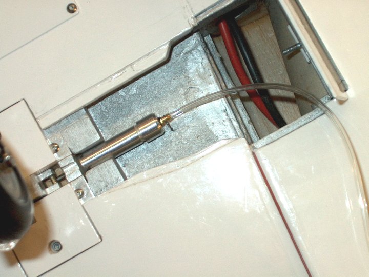
doors and retract cover, then the insides were painted with
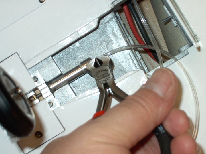
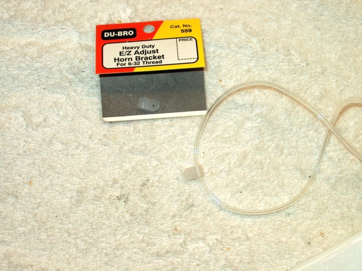
aluminum paint. | |
139 - Retract Assembly area covered,
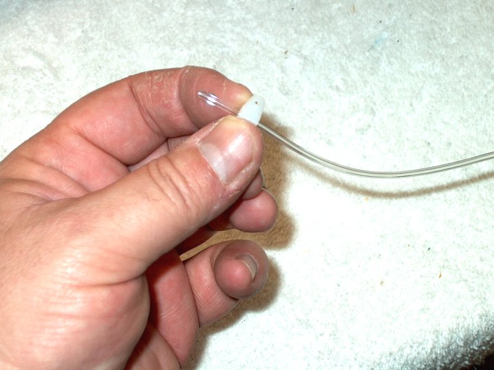
painted and installed. | |
140 - Finished Retract area with doors
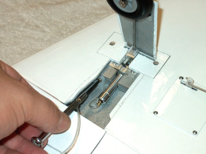
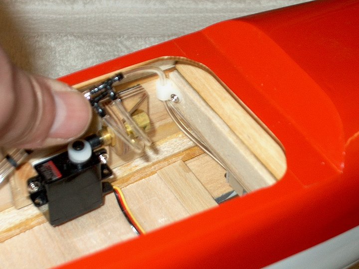
closed. | |
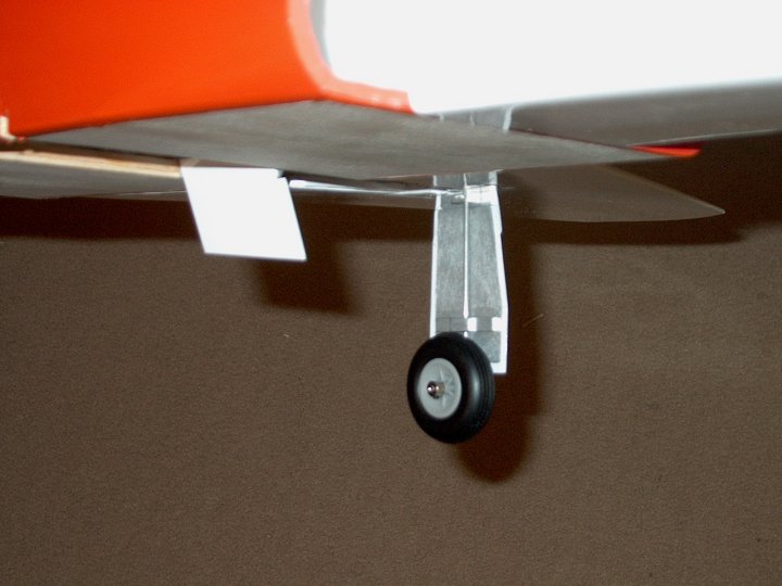
141 - Upright View of the retract
Assembly. | |
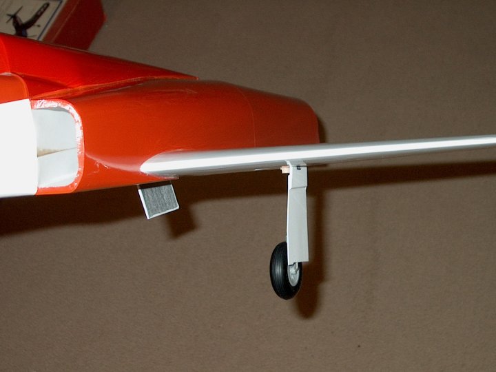
142 - Retract Outside View.
| |
143 - Starting the second wing. Covering
is ironed down to remove wrinkles. | |
144 - Masking tape is stacked to make a
block, then positioned so the wing rear top butts against it
and the wing rear bottom is positioned 1mm from the bottom of
the fuselage. | |
145 - Fuselage is marked once the wing is
in place. | |
146 - Wing pattern marked on
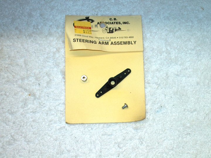
fuselage. |
|
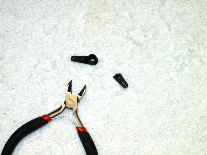
147 - A razor is used to cut inside the
drawn line. |
|
148 - Covering is removed so there is a
good glue surface. |
|
149 - Once cut, the covering is ironed to
seal the edges. |
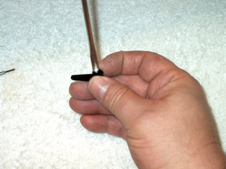
|
150 - Area shown ready for epoxy. Marker
can be cleaned with alcohol . | |
151 - Front and rear of fuselage are used
for alignment to draw on wing. | |
152 - Dimension lines shown drawn.
| |
153 - Forward line is cut, then the
outside line and finally cut on the "Spar Front" line.
| |
154 - A razor or saw can be used to cut
through the root spar. | |
155 - A razor was used to cut the spar at
the covering, then a long razor was used to saw
through. | |
156 - Using a razor, carefully remove the
balsa block. Be careful not to crack the wing sheeting below;
the block is thick and mounted well.
| |
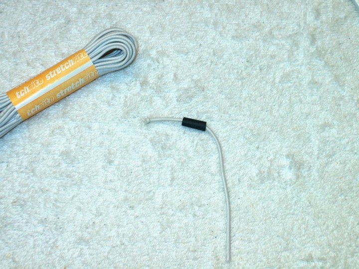
157 - Balsa block removed.
| |
158 - Wing area is cleaned out.
| |
159 - The rest of the balsa block is
shaved out. | |
160 - Wing area is sanded with 100 grit to
remove glue, foam and balsa from the block.
| |
161 - Wing prepared and ready to install.
Note the wing sheeting on the left that remains to help with
spar alignment when glued. | |
162 - Wing is installed in place and fit
is checked before gluing. | |
163 - Photo shows wing bottom.
| |
164 - Hole in wing for Aileron servo wire
was cleaned out. | |
165 - Hole for Aileron servo wire cleaned
out in fuselage and enlarged. | |
166 - Make sure the hole for the Aileron
wire is aligned on both parts. | |
167 - Epoxy is applied to the Spar Slot
and the Wing Spar is installed. | |
168 - 15 Minute epoxy has been added to
the Fuselage area, Spar and Wing. Do not add epoxy to the
front of the Spar, but rather only the rear where it contacts
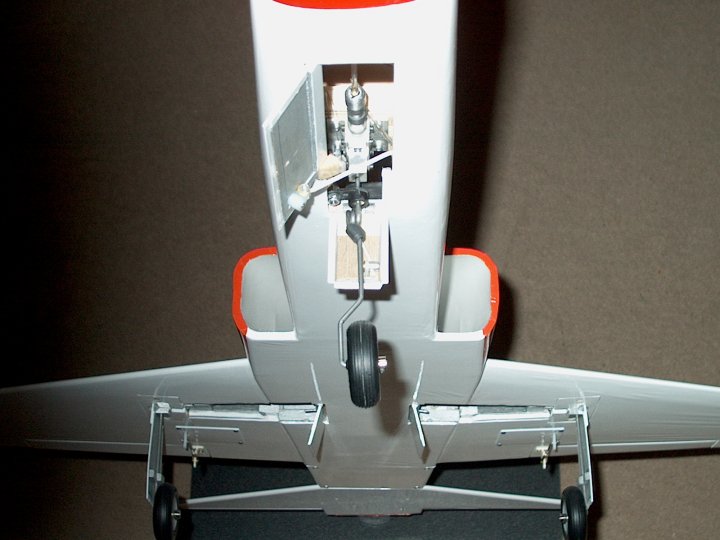
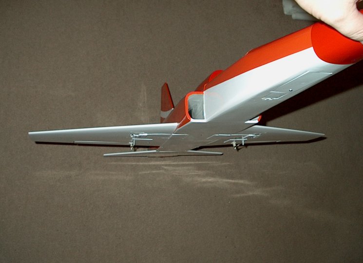
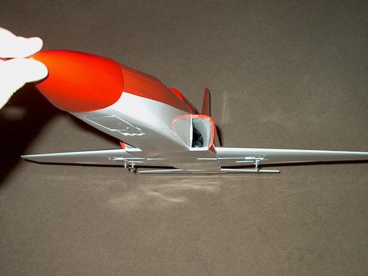
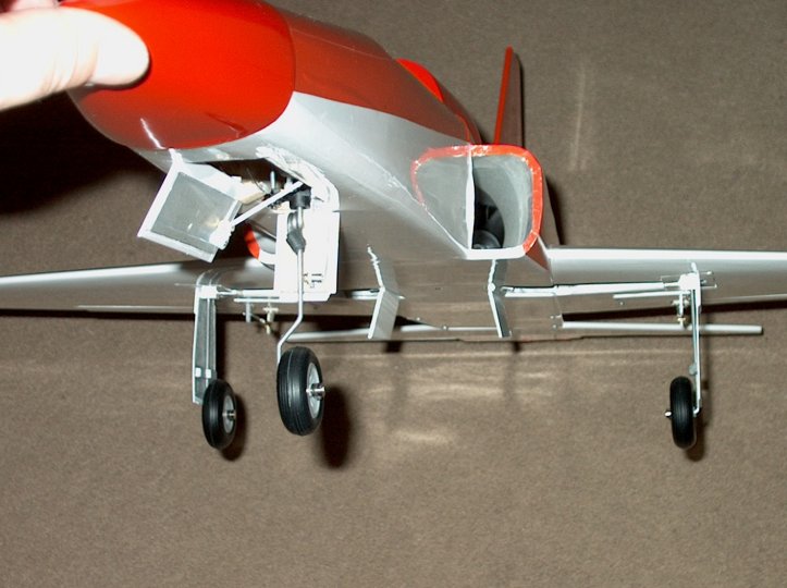
the wing. | |
169 - Wing is installed on Fuselage and a
clamp is used to hold the spar in place. Check rear alignment
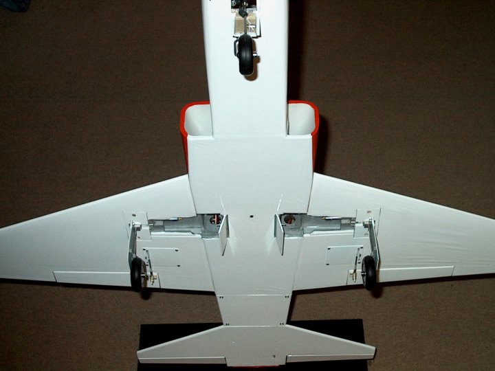
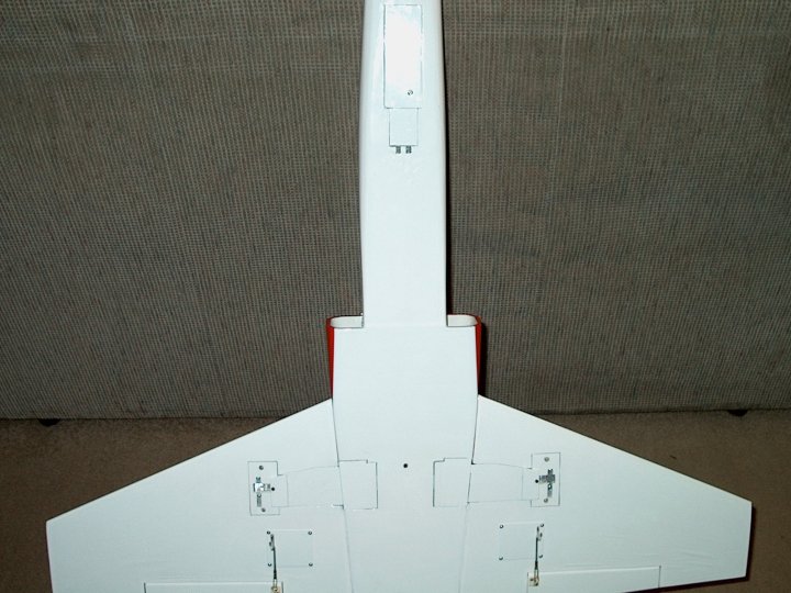
at 1mm and follow the normal installation instructions. Note
that there is a slight Dihedral in the wing. Clean up the
excess epoxy with denatured alcohol.
| |
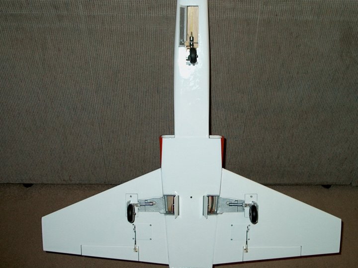
170 - Wing shown clamped in place while
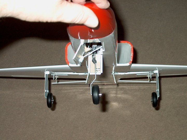
epoxy sets. | |
171 - Second Wing installation
completed. | |
172 - Use a razor to cut the sheeting at
the "Spar Rear" line. It is best to do this while epoxy is
still soft. | |
173 - A razor saw is used to remove the
fuselage area. The cut is flush with the rear former.
| |
174 - Fuselage side removed for wheel
clearance. | |
175 - The second gear wire is bent and cut
the same as the first. | |
176 - Gear wires match and are ready to
install. | |
177 - Patterns previously drawn on 1/8"
ply for retract framework from templates. They are cut out and
fitted to the retract bay. | |
178 - Main Spar is notched to clear
retract tray. | |
179 - Piece from Main Spar is removed.
| |
180 - All pieces for the Retract framework
are cut and fit. | |
181 - Main Spar is notched to clear
retract tray. | |
182 - Piece from Main Spar is removed.
| |
183 - All pieces for the Retract framework
are cut and fit. | |
184 - Main Spar is notched to clear
retract tray. | |
185 - Piece from Main Spar is removed.
| |
186 - All pieces for the Retract framework
are cut and fit. | |
187 - Main Spar is notched to clear
retract tray. | |
188 - Piece from Main Spar is removed.
| |
189 - All pieces for the Retract framework
are cut and fit. | |
190 - Main Spar is notched to clear
retract tray. | |
191 - Piece from Main Spar is removed.
| |
192 - All pieces for the Retract framework
are cut and fit. | |
193 - Main Spar is notched to clear
retract tray. | |
194 - Piece from Main Spar is removed.
| |
195 - All pieces for the Retract framework
are cut and fit. | |
196 - Cover is installed in place.
| |
197 - Cover is sanded flush to the wing.
| |
198 - Balsa Cover shaped and
completed. | |
199 - Retract installed to work on gear
door next. | |
200 - Door is cut from pattern from 1/32"
ply and top cap is shown and cut from 1/16" ply.
| |
201 - Retract Door set in place and marks
made on balsa cover. | |
202 - Base made for lower door frame from
3/16" balsa. | |
203 - Piece is set in place.
| |
204 - The door is positioned and drawn on
the balsa frame piece. | |
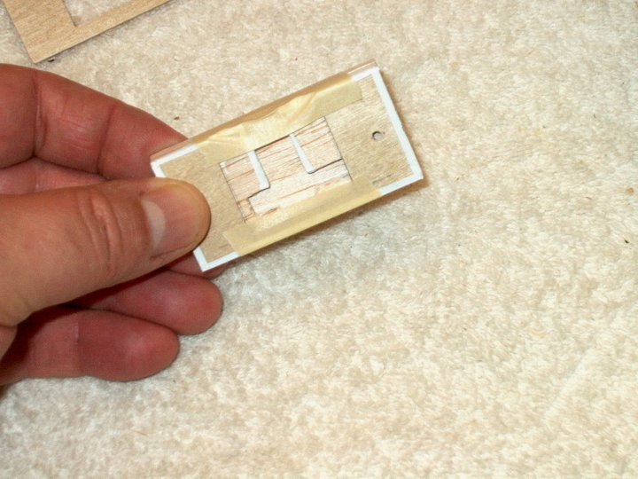
205 - A mark is made parallel to the side of the piece and then
cut to shape along both lines. | |
206 - Door frame piece is cut and
installed. | |
207 - Frame glued in place.
| |
208 - A piece of 3/32" scrap was placed
under the door. | |
209 - The door was drawn on the
balsa. | |
210 - The balsa upper frame was
cut. | |
211 - Upper frame piece is glued in
place. | |
212 - Rear lower frame made from 3/16"
balsa. | |
213 - Once again, the door is used as a
guide to mark the frame. | |
214 - Lower frame cut and glued in place.
Photo shows cap piece of 3/32" balsa to even the door area
with the wing sheeting. | |
215 - Front and Rear Door Frames
installed, then sanded flush with the wing sheeting. The edges
of the frame pieces are touched with thin CyA to add
strength. | |
216 - A Lower Gear Door Bracket is cut
from 1/8" ply. | |
217 - It is evenly spaced on both sides
from the base of the retract. | |
218 - Gear Wire location marked on the ply
bracket.
| |
219 - A 5/8" long piece of 1/8" ply is
glued to the top, centered over the marks. Then a slot is cut
between the two marks to fit it around the gear. | |
220 - Ply bracket glued in place one
position is checked. | |
221 - Lower bracket shown installed on
gear. | |
222 - Wheel Door installation completed.
| |
223 - Fuselage door is cut from 1/32" ply
and fitted in place. | |
224 - Top piece of 1/16" balsa is
cross-grain laminated to the ply door.
| |
225 - Fuselage Door ledge glued at rear
former, even with the top of the Ply Bulkhead, leaving it
recessed for door clearance. | |
226 - Fuselage Door tacked in place to
sand. | |
227 - Door is sanded flush with Fuselage
bottom. | |
228 - Door is flipped over and a 1/16" ply
strip is added, then a 1/16" wire is cut, set on top of the
first ply strip and sandwiched between two narrower strips of
1/16" thick ply. | |

229 - A 1/32" piece of ply is made to cap
the top of the wire channel. | |
230 - Marks are made for the 2-56 pushrod
that closes the door. | |
231 - Punch is used and a hole is drilled
for the rod. Make sure the 1/16" wire is installed and drill
at a slight angle.
| |
232 - Rod is epoxied in place. | |
233 - A flex drill with a 1/16" bit is
used to drill the holes for the door hinge wire. They are
drilled 3/32" down from the top of the balsa door ledge on the
right. | |
234 - Wire holes drilled. Take your time
and adjust the door height by filing the hole upward or
downward as needed for the door to close flush without
binding. The excess space can be filled with a toothpick and
glue.
| |
235 - Door installed and aligned. | |
236 - Fuselage Door Stop installed at
bottom as shown in photo.
| |
237 - Make sure the Fuselage Gear Door has
at least 1/8 - 1/4" clearance for the wheel to clear. | |
238 - Retract shown closed in up position.
check for binding.
| |
239 - A piece of 1/4" x 3/8" maple is used
both as a center fuselage brace and door tension wire holder.
A 1/16" hole is drilled through the wood. | |
240 - Hole has a tapered opening carved to
ease wire installation. | |
241 - Hole drilled through top of Maple
centered over horizontal hole area.
| |
242 - Door Tension Wire is installed and a
2-56 bolt is cut to length and used to cut threads into the
Maple. The threads are then stiffened with thin CA. The music
wire is .015 diameter and 7 3/4" long to start, then trimmed
at final installation to adjust tension. | |
243 - The center of the Fuselage is
marked. | |
244 - Epoxy is used to install the Maple
support. | |
245 - 1/4" balsa triangle is added on the
rear side to support the balsa sheeting. Make sure you have at
least 1/4" clearance between the end of the triangle and the
door so the door can open without binding.
| |
246 - Triangle installed and area is ready
for sheeting. | |
247 - Balsa sheeting is rough cut.
| |
248 - The edges are beveled to clear the
doors when they open, then they are stiffened with thin CA.
| |
249 - Sheeting is set in place and sanded
for a good fit. The doors should not bind when opening.
| |
250 - Sheeting is held in place, then
pushed down on the 2-56 bolt area to mark for drilling. | |
251 - Hole is drilled to clear the bolt.
| |
252 - Balsa sheeting glued in place with
CA. Make sure clearance is even on both doors.
| |
253 - Sheeting is sanded flush to the
bottom of the fuselage. | |
254 - Bungee hook block is removed by
grabbing with pliers and twisting. | |
255 - Wing, Retract Cover and Doors were
covered with white covering and the wheel bay was painted with
silver paint.
| |
256 - Wing Retracts are installed to
assist with measuring nose gear height. | |
257 - Landing gear installed...it has a
nice wide stance. | |
258 - A filler piece of balsa is installed
in the door area, then sanded flush and checked for clearance
and binding.
| |
259 - Piece of plastic tube from an
antenna wire guide cut to 5/8" long and epoxied in place on
the door. This will hold the door spring wire. | |
260 - Side view showing position. The tube
was also covered in place.
| |
261 - Fuselage Door installed. | |
262 - Tension wire being installed in the
tube. The wire is made extra long so the tip butts excessively
against the firewall. Tension adjustment is made by inserting
the wire through the center retainer, then through the tube as
shown and continuing until the wire end butts against the
former wall. Push the wire from the other side until tension
is set, then lock the center screw. Insert the wire through
the tube on the second door and butt it's end against the
former wall, then it back until tension is set correctly.
| |
263 - Nose Gear Retract Installation: A
line is drawn on the Fuselage for reference. | |
264 - The center from the sides of the
Fuselage is marked. | |
265 - A ruler is used to mark 7 1/2"
forward from the previous line. | |
266 - A line is then drawn across the
fuselage. | |
267 - A center line is drawn down the
middle of the fuselage. | |
268 - The "rear" of the Retract is
positioned at the line and its outline drawn.
| |
269 - Initial lines drawn. | |
270 - Area cut from bottom of
fuselage. | |
271 - Saw used to cut and remove former
bottom.
| |
272 - Area ready for retract plate. | |
|
274 - I put a bend at the top to re-align
the gear shafts.. | |
275 - Front Wire Gear shown bent to
shape. | |
276 - A plastic button was drilled for the
3/32" wire and installed. | |
277 - Button is installed and used to
space the wheel. | |
278 - 1 1/2" wheel and Wheel Collar
installed. | |
279 - Top of the wire is marked at 7/8" in
length from the spring. | |
280 - Wire is cut to length.
| |
281 - Wire shown with gear
installed. | |
282 - Plywood Plate cut from 1/8" ply for
retract mount. | |
283 - Centerline was drawn and retract
evenly spaced, then holes were drilled and retract was
mounted. | |
284 - Plate shown recessed in
fuselage. | |
285 - Plate had to be slightly tapered to
fit the fuselage. Sand until it fits well. Two pieces of 1/2"
square balsa are cut as supports for the plate.
| |
286 - Balsa Supports are epoxied to the
plate, flush to the outsides. | |
287 - Holes are re-drilled to clean out
excess epoxy. | |
288 - Plate is temporarily installed with
the rear balsa square against the ply cockpit former while the
front is butted against the forward former as shown, then
lines are drawn for gluing. | |
289 - Epoxy is applied to the plate, then
, with the back part of the plate pressed down flush to the
former, you should measure 1 7/16" to the top edge of the
fuselage. Make sure the plate is not tilted forward; adjust it
evenly at both the front and rear. | |
290 - Plate is shown glued in
place. | |
291 - A mark is made back 1/4" from the
wheel opening. | |
292 - The strip is cut only 1/16"
deep. | |
293 - Area is chiseled out then replaced
with a 1/16" thick piece of ply for extra support. The ply is
epoxied in place. | |
294 - The inside of the cockpit floor is
very thin, so it was reinforced with 1/8" balsa strips shown
above and below the center spar. | |
295 - A 1/32" piece of ply is cut 1 1/2" x
1 1/4" as a servo support plate. One side is glazed with thin
CA and sanded so the servo tape has a smooth mounting
surface. | |

296 - Epoxy is applied and the 1/16" thick
ply brace is installed on the floor of the cockpit
area. | |
297 - The servo plate is installed on the
cockpit floor area in the fuselage.
| |
298 - Steering Servo plate shown
installed. | |
299 - Steering servo shown...a HS-81 was
used. Be sure to center the servo arm before proceeding. I
used a servo tester to center the servo. A ball mount is
connected to the outer arm hole. | |
300 - The top of the gear wire is notched
for better retention.
| |
301 - Gear wire is installed with steering
arm, then the servo is held in place and a pushrod wire is
shown below having been marked for bend. | |
302 - Wire needed to be ground down a bit
in diameter to fit the steering arm hole, then it was bent at
the mark. | |
303 - The Steering Pushrod Assembly shown
as completed.
| |
304 - The servo is held in place and
adjusted/lowered for alignment as shown. | |
305 - View of the pushrod connected to the
steering arm. | |
306 - The mounting side of the servo is
cleaned with Acetone. | |
307 - Servo tape is applied to the
servo. | |

308 - Steering Servo is mounted in
place. | |
309 - Forward Retract Landing Gear shown
installed. | |
310 - A 1/8" thick plywood frame is made
for the air valve. It is 3/4" square and assembled with epoxy.
| |
311 - A mark is made for the valve
mounting hole and the front and rear of the plate are coated
with thin CA so the ply will not chip when drilling. | |
312 - A 1/4" drill is used to make the
hole.
| |
313 - The mount is epoxied to a piece of
1/16" thick ply plate that measures 2 1/4" x 1 1/2". | |
314 - The air valve switch is installed.
This is the switch used by Bob Violett as a door switch. You
can use other air switches, but will need to make the mount
fit your selection. | |
315 - Air switch temporarily installed.
| |
316 - A HS-56 Karbonite servo is used with
the air switch. The servo arm was cut into an "egg" shape,
similar to a lobe on a camshaft. It is long enough to
completely depress the switch in one position, while allowing
the switch to completely open in the other position. With the
servo arm this short, the maximum amount of pressure it can
produce is applied to the switch button. Also, using a "lobe"
like this prevents overstressing of the servo as the arm can
not bind.
| |
317 - The mounting side of the servo is
cleaned with Acetone. A double thick layer of servo tape was
installed in order to bring the center of the servo in line
with the center of the switch, from a top view. | |
318 - Small servo mounting blocks are cut
from maple. | |
319 - The maple blocks are saturated in
CA, then drilled and installed on the servo. Note the blocks
are high enough to come flush to the bottom of two layers of
servo tape. | |
320 - The top of the ply plate is coated
with thin CA, then sanded smooth. | |
321 - Servo tape is shown being prepared
to install. Note that the bottom of the tape is flush with the
bottom of the maple mounts. | |
322 - A dab of epoxy is applied to each
maple block, then the servo is carefully positioned so it is
just touching the switch, then clamped in place until the
epoxy sets.
| |
323 - Photo showing correct position of
the servo. The arm is in line with the switch center. | |
324 - Servo arm lobe and switch shown in
the opened position. | |
325 - Servo arm lobe and switch shown in
the closed position. | |
326 - A 1/32" x 3/8" piece of ply was
epoxied in place as shown to add support for the rear door
hinges. | |
327 - Balsa supports were added to this
fuselage front. If you cut your door hole to the new length,
this will not be needed. | |
328 - Side supports made from 1/8"
Balsa. | |
329 - Supports cut to proper spacing.
| |
330 - Side support panels glued in
place. | |
331 - Filler pieces cut from 3/16"
balsa.
| |
332 - Filler pieces set in place.
| |
333 - Pieces are each glued using epoxy,
then their height is adjusted using a 1/32" piece of ply that
will be used for the door. They should be made so the door
piece is flush to the rear and side. | |
334 - Inner rear door made from 1/8" balsa
and a 1/32" x 3/8" wide piece of ply, which is installed flush
to the balsa.
| |
335 - A view of the 1/8" lip that will
assist with keeping the door in place during flight. | |
336 - The inner door is epoxied to the
outer door made from 1/32" ply. | |
337 - Door is beveled on three sides at
the balsa.
| |
338 - Door checked for fit.
| |
339 - A 1/32" x 3/8" wide piece of ply is
epoxied to the rear for hinge support, then a drill and needle
file is used to open up the holes for the hinges. | |
340 - Rear of the fuselage door support
are is removed with a knife and drilled with a 1/8"
bit. | |
341 - Robart hinges are used and shortened
to fit the door. 341 - Robart hinges are used and shortened to
fit the door. | |
342 - Hinges installed in place and door
closed to check for fit. | |
343 - Door opened to check for
binding. | |
344 - Retract screws are still accessible
for maintenance. | |
345 - Photo of Rear Door installed with
retract down. | |
346 - Small 1/32" ply strips used as door
frame sides and glued in place. | |
347 - Balsa filler sheeting added to the
sides of the door. | |
348 - 3/32" balsa added to each side so
the bottom of the fuselage could be shaped.
| |
349 - Bottom of the fuselage is then
sanded and shaped flush. | |
350 - Rear door area finished and sanding
/ shaping is completed. | |
351 - Both doors cut and set in
place. | |
352 - Hinge added to side of wheel door
using 1/16" ply and wire. | |
353 - Channel epoxied in place and ready
to trim. | |
354 - Forward area removed for ply plate.
| |
355 - 1/2" square ply plate is epoxied in
place to support the hinge area. | |
356 - Plate shown installed.
| |
357 - Inner frame being epoxied to door to
help stiffen the assembly. | |
358 - Wheel Door installed showing inner
frame and wire hinge. | |
359 - The bottom of the Fuselage is
recovered in white. | |
360 - The area around the door opening is
finished. | |
361 - Doors are covering and checked for
fit. | |
362 - Tail cone is roughed up with 60 grit
sandpaper, then 5 minute epoxy is used to attach it to the
tail of the model. | |
363 - I used the canopy from my other F-20
to mark the cutout lines.
| |
364 - Canopy trimmed so it could be
installed and CG checked to see if components could be mounted
fore or aft. We wound up mounting the Receiver and U-BEC in
the rear of the model as the standard instructions show. CG is
very manageable with the this setup. | |
365 - Heat Shrink is used on the Steering
Servo and Retract Servo extensions to insure they will not
pull apart. | |
366 - A 3/16" hole was drilled on the
right side for the servo wires. | |
367 - Servo tape installed on the Retract
Servo Assembly.
| |
368 - The Retract Servo Assembly is
mounted on the forward left side of the cockpit area.
| |
369 - Retract Servo Assembly in place.
Enough room was left (approx 3/4") to the right side so the
air switch could be removed for maintenance. | |
370 - Wires were routed and wires ties
were used to keep it clean. | |
371 - Stainless wire was used to secure
the air lines at each cylinder.
| |
372 - The wire was pre-wrapped and placed
over each air line prior to installation.. | |
373 - The Air Line was heated with a Heat
Gun to make it slightly soft and easier to install over the
cylinder fitting. | |
374 - Air Line is secured with the
stainless wire. | |
375 - Wires is trimmed to about 1/4" in
length. | |
376 - Air line installed on wing retract
cylinder. | |
377 - Horn Brackets were used to dress up
the air line routing. 3/32" -6/32" brackets can be used...I
used what I had laying around.
| |
378 - A small screw that came with the
servo was used to install the bracket. | |
379 - A drill bit was then inserted into
the hose end to help weight it down and make running it inside
the fuselage much easier.
| |
380 - Hose and drill is pulled to the
front of the cockpit area from the wing. | |
381 - A second Bracket was installed to
help keep the air line out of the way of the wheel.
| |
382 - Both air lines from the wing have
been pulled forward and a 1/4" drill is used to make a hole to
pass the lines through. | |
383 - Air lines for the wing retracts
shown routed through the hole.
| |
384 - A small Pressure Tank was used. It
is just under 4" in length and out worked well. Photo shows
air line installed and ready for installation. | |
385 - Velcro is attached to the tank so it
can be removed later if necessary.
| |
386 - The tank is installed with its rear
passing through the rear top former hole and the velcro is
fastened to the top inside of the turtle deck area. | |
387 - The tank line is run forward and
pieces of heat shrink are cut to make a harness for the air
lines. | |
388 - The two wing cylinders are connected
with the "T" fitting on the left and then to a second "T" that
goes to the switch and forward retract cylinder. The tank is
connected to a "T" that runs down to the air switch and out to
a hose for a fill valve. | |
389 - Horn brackets are once again used as
air line retainers. | |
390 - The horn bracket is installed..
| |
391 - Heat shrink is placed over the
retract cylinder to hold the line in place.
| |
392 - Air line installed on the front
retract cylinder.
| |
393 - Air line run completed. | |
394 - Fill Valve is installed on the tank
line. | |
395 - The plastic steering rod shown below
was not long enough, so the steering bracket would pull off
the top of the rod when retracted. A new steering assembly
needed to be made. | |
396 - A spare steering arm was
used. | |
397 - One end of the steering arm was cut
off. Make sure you cut it so the lock screw is facing rearward
when installed. | |
398 - Locking bolt is installed in the
steering arm. | |
399 - The arm is trimmed short, right up
to the closest hole. | |
400 - A mark is made to drill a new
hole. | |
401 - A hole is drilled for a 4-40
threaded rod. | |
402 - A nut is installed on the rod and
secured with Loktite. | |
403 - The nut is tightened until it
bottoms on the rod. | |
404 - The hole that was drilled is tapped
with a 4-40 tap set. | |
405 - The rod is threaded in the steering
arm, then a nut is used for spacing and the rod is marked for
cutting. | |
406 - The threaded rod is cut to correct
length. | |
407 - Rod cut and threads cleaned
up. | |
408 - Rod is re-installed in the steering
arm. | |
409 - A nylon lock nut is
installed. | |
410 - The steering rod is installed and
ready for trimming to length. | |
411 - The old steering arm is used to mark
it's length on the rod. | |
412 - A mark is made 1/4" above the first
mark. | |
413 - The wire is cut, then fit and ground
until is clears the retract frame.
| |
414 - Retract is shown in the up position.
The old rod's mark is still seen and you can see about 3/16"
was extended, longer than the old rod. | |
415 - The old slide bracket could be
re-used as it fit the 4-40 rod perfectly. Gear shown in "UP"
Position. | |
416 - Gear shown in "DOWN"
position. | |
417 - View shows servo, control rod and
new steering arm.
| |
418 - To mount the front door, the wire
should be installed in the front first. | |
419 - The rear of the door is placed in
position. | |
420 - Pliers are used to work the hinge
wire into its hole. | |
421 - The forward door is shown
installed.
| |
422 - A 4-40 button head screw and 3/32"
Horn Bracket are used for the door mechanism. | |
423 - The Screw is installed in order to
cut threads in the bracket. | |
424 - The screw is marked and then cut
flush. | |
425 - Elastic cord is used for a door
puller. | |
426 - The mount is positioned and
installed as shown.
| |
427 - A piece of 1/4" x 3/8" maple is
drilled on the 1/4" side for the cord. | |
428 - A knot is tied in the cord and
sealed with epoxy, then installed. | |
429 - The block is epoxied to the inside
of the fuselage. | |
430 - The set screw is used for adjustment
so the door completely closes.
| |
431 - A wire retainer is made from 1/4" x
3/8" maple and a piece of plastic antenna tube. | |
432 - The block is epoxied in
place. | |
433 - A piece of .015 music wire is used
for the door spring. | |
434 - The wire is installed in the tube
and holds the door open.
| |
435 - The wire door spring shown from a
top view. When open, pressure is applied to the left of center
and holds the door open. When closed, pressure is applied to
the right of center and springs the door closed.
| |
436 - Photo shows wire end bends for
installation and retention in the plastic tube.
| |
437 - Hinges are mounted in the small door
so the door can be used to install them in the fuselage. | |
438 - Hinges are glued in place with
epoxy. Be very careful not to get epoxy in the hinge
points. | |
439 - Door is mounted to the hinges to
check for fit.
| |
440 - A Horn Bracket will be used to close
the small door. The bottom is trimmed off. | |
441 - Bracket shown cut and ready to
install. | |
442 - Hinge Bracket is installed in door
after area cut out. | |
443 - Door cover panel cut from thin ply
and epoxy over the door plate.
| |
444 - A piece of fuel tubing is used to
hold the elastic cord for the small door. | |
445 - The cord is tied to the tubing
several times. | |
446 - A hinge point is mounted to the door
bracket.
| |
447 - Hinge point installed. | |
448 - Heat shrink placed over the elastic
knot for the fuel tube. | |
449 - Door is epoxied to the the hinges
and left to set.
| |
450 - Elastic is installed and tension is
adjusted, then set screw is tightened. | |
451 - Retract Installation - Lower Front
View. | |
452 - Retract Installation - Full View of
Retracts Down. | |
453 - Retract Installation - Bottom View
Retracts Down. | |
454 - Retract Installation - Bottom View
Retracts up, All Doors Closed. | |
455 - Retract Installation - Full Bottom
View of Retracts Up. | |
456 - Retract Installation - Right Side
Retracts Up. | |
457 - Retract Installation - Left Side
Retracts Up. | |
458 -Retract Installation - Angled View
Retracts Down. | |
459 - Retract Installation - Head On View
Retracts Down. | |
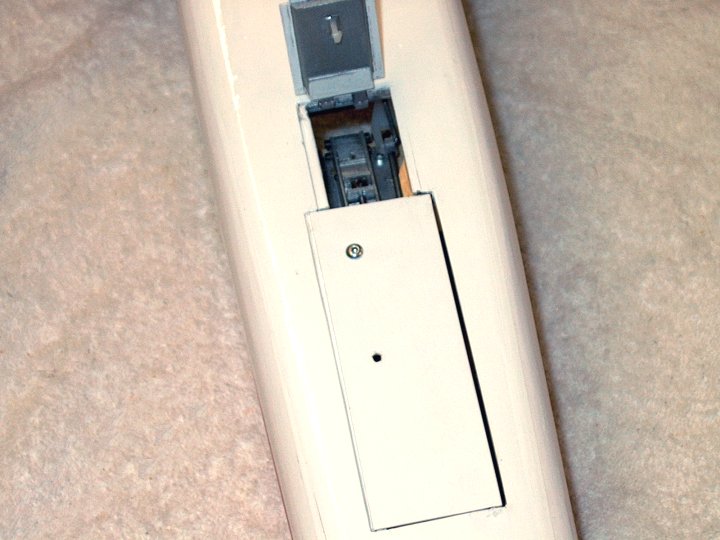
460 - The HET-RC F-20 Tigershark EDF Jet Retract
Conversion | |

This Website and all documents herin are Copyright © 2012 www.scalerocketry.com -
All rights reserved.
| |