1 - The F-20 as it comes in the
box.
|
|
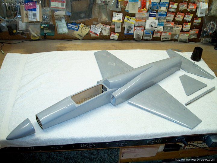
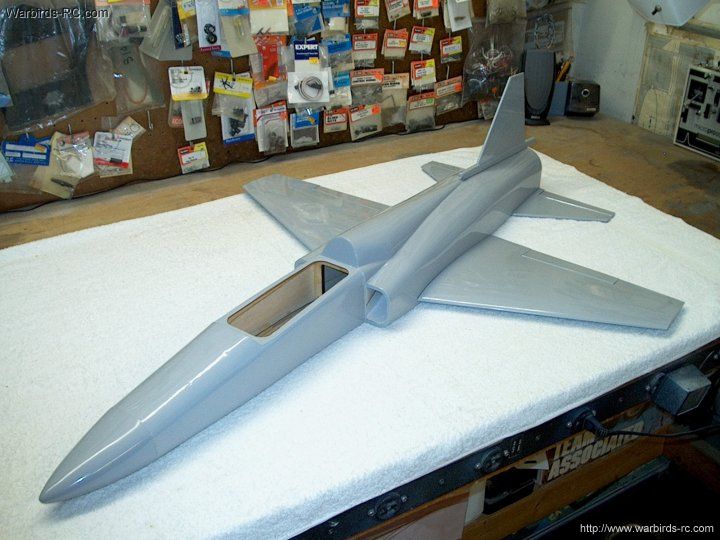
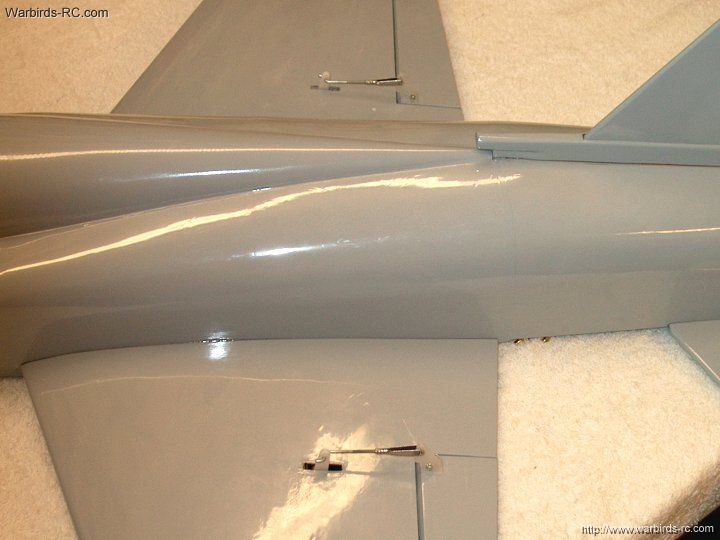
2 - The HET-RC ARF Minifan 480 sized F-20
Tigershark shown out of the box
| |
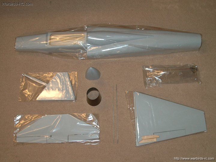
3 - The major components of the model are shown.
It is very similar to the HET-RC FA-18 in construction and covering
Tigershark.
| |
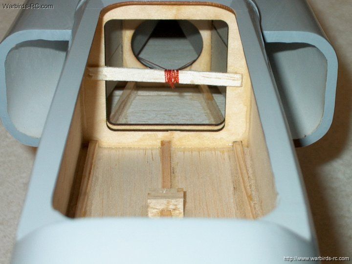
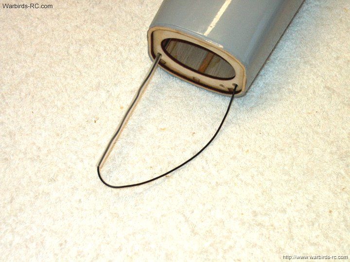
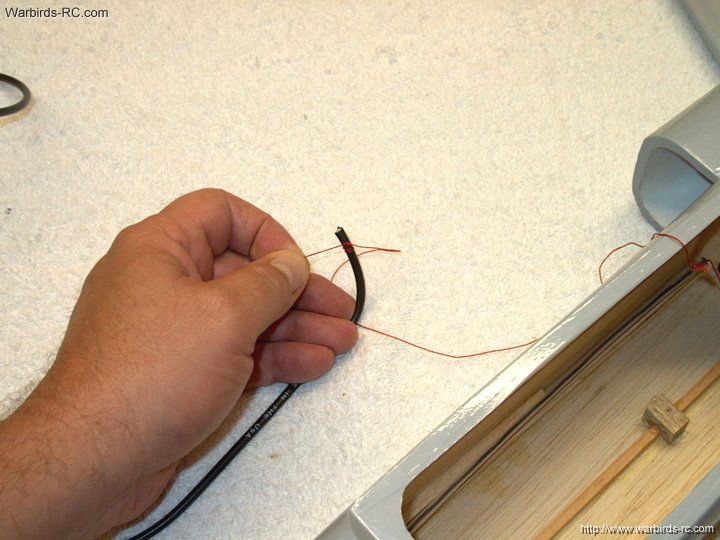
4 - The model comes complete with pre-strung
red cord wire pullers
CG. | |
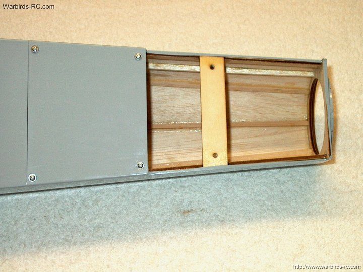
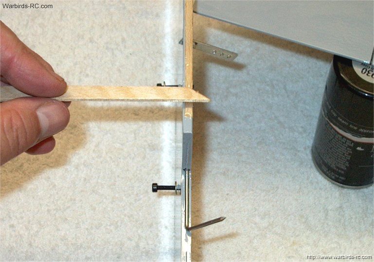
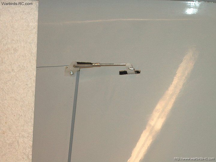
5 - The Elevator area shows bolt mounts for
easy alignment
| |
6 - The fan area with blind nuts pre installed
for fan mounts
| |
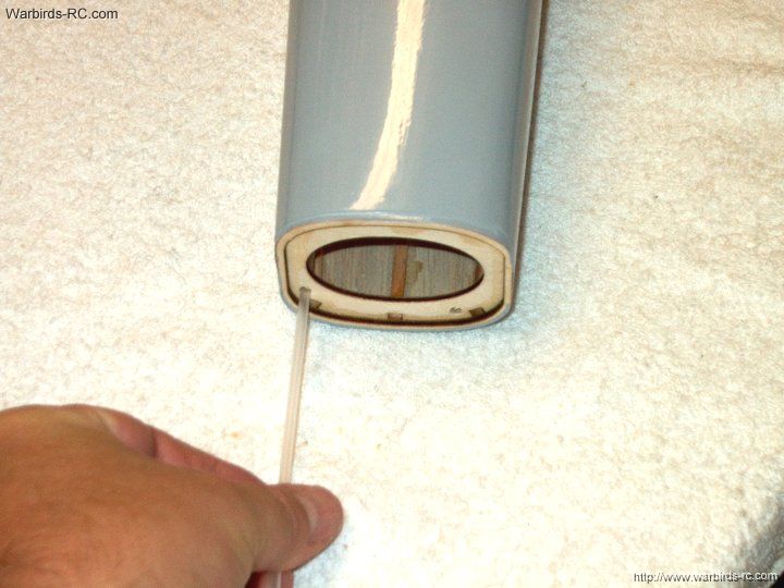
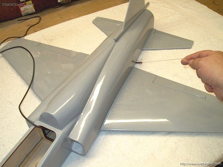
7 - The other end of the red cord wire pullers.
These ports are used for Aileron servo leads, ESC power wires
and Receiver antenna
| |
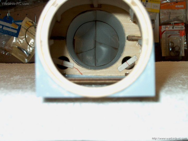
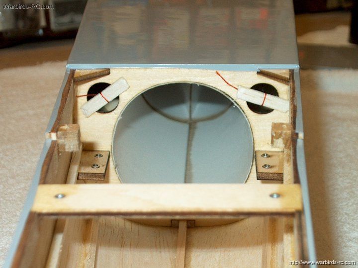
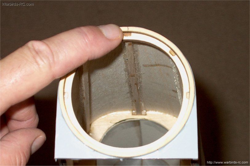
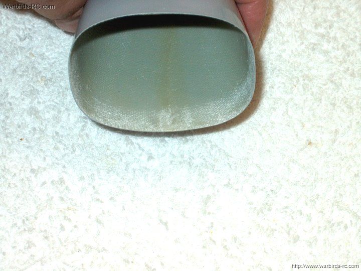
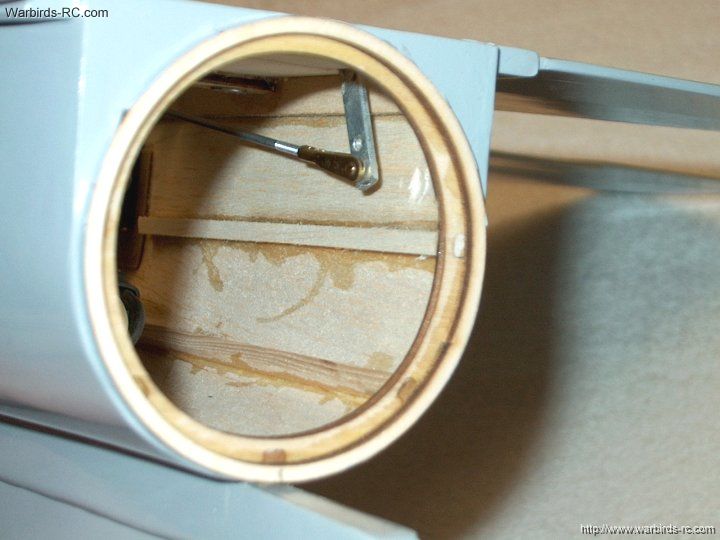
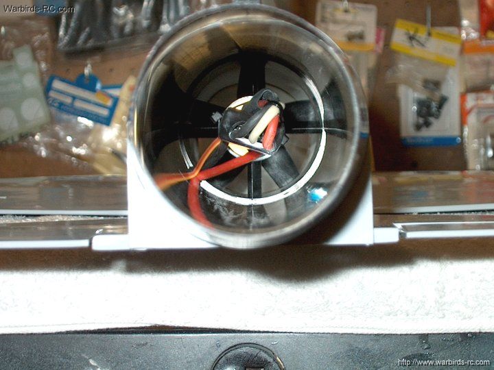
8 - Shown is a view of the ducting area from
the end of the model
| |
9 - Aileron Servo bays come already cut under
the covering
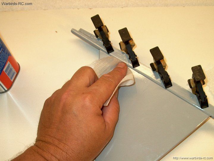
| |
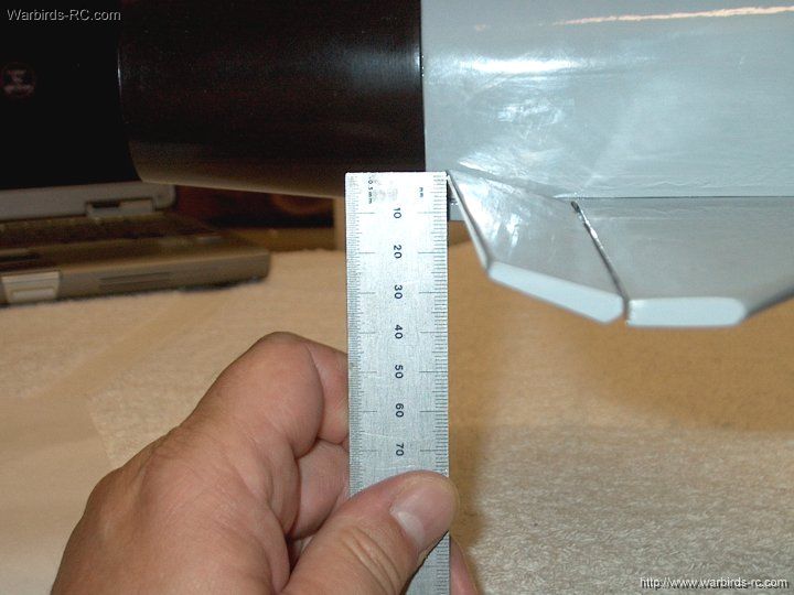
10 - The wing cord is 13/16" thick, which
makes it a good candidate for Retracts
| |
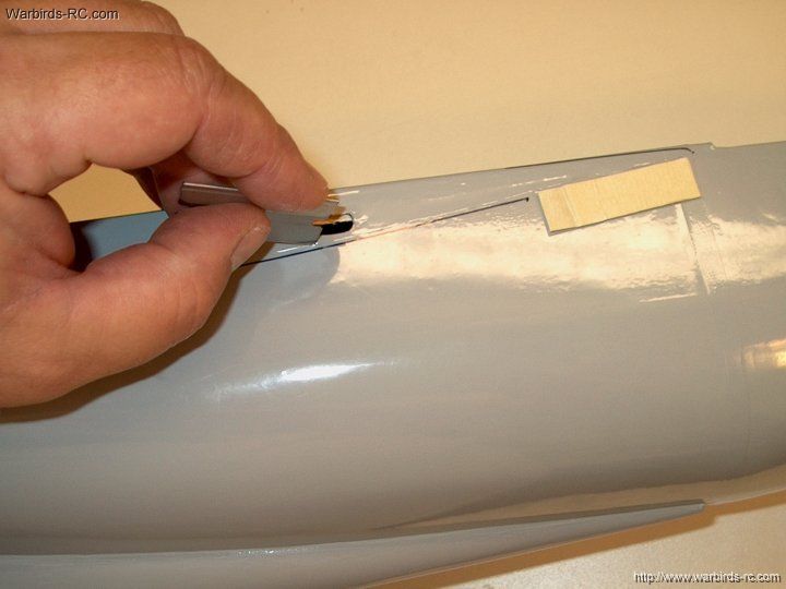
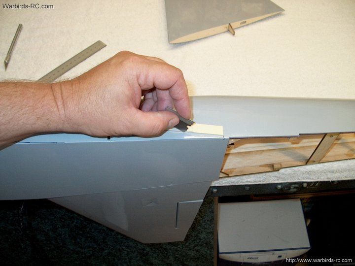
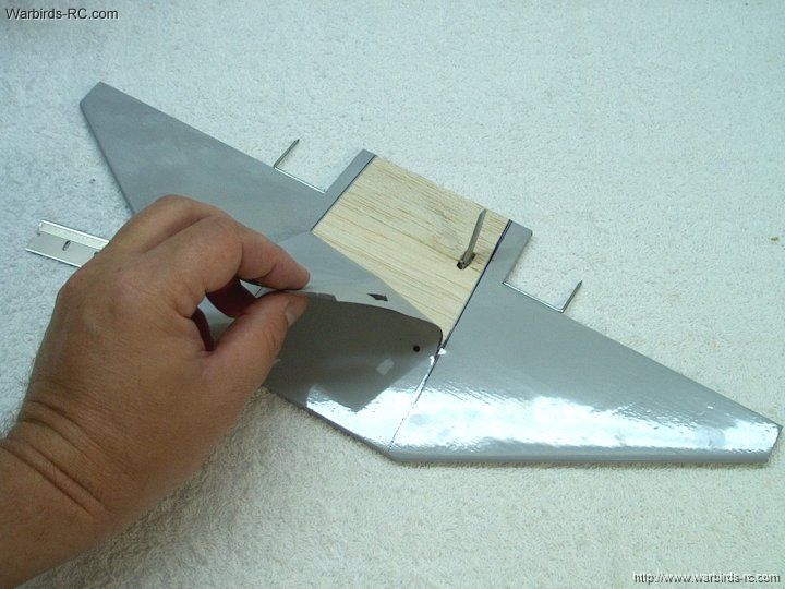
11 - Time to build...Start by trimming
away the covering from the Wing Spar and Aileron Servo holes
| |
12 - Clear the holes of covering
| |
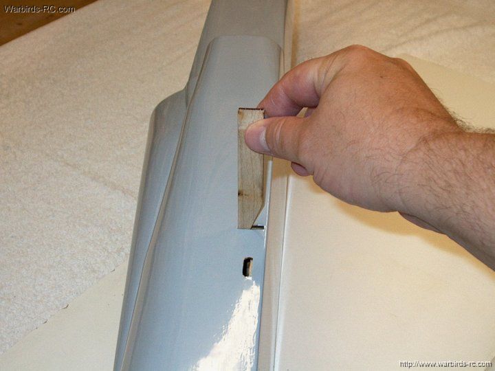
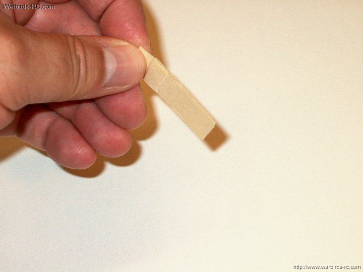
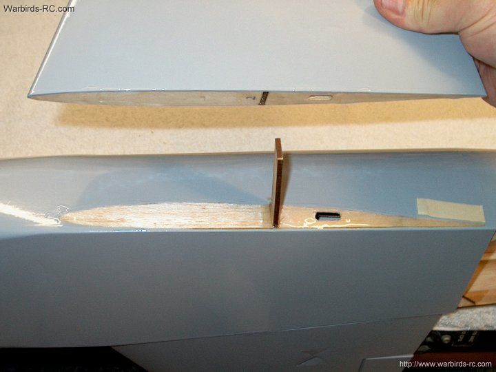
13 - Insert wing spar with the angled edge
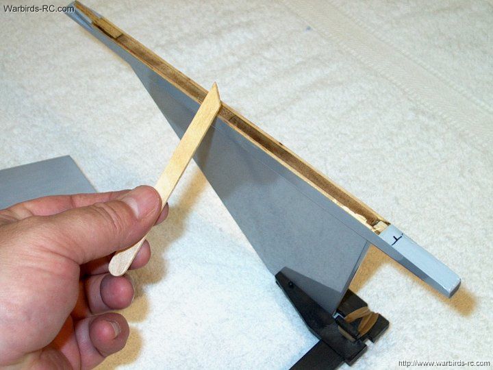
facing downward in the fuselage. It is keyed inside so you can't
get it wrong
| |
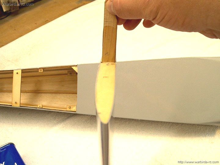
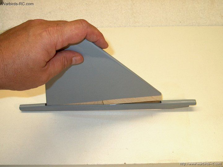
14 - Temporarily install the wing
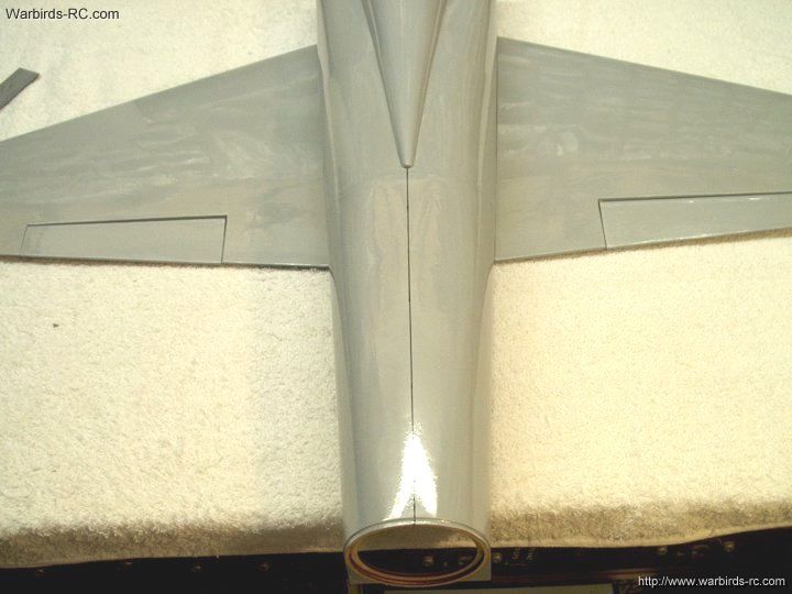
| |
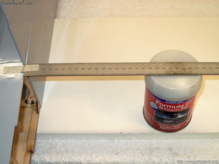
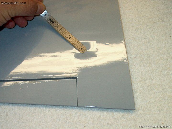
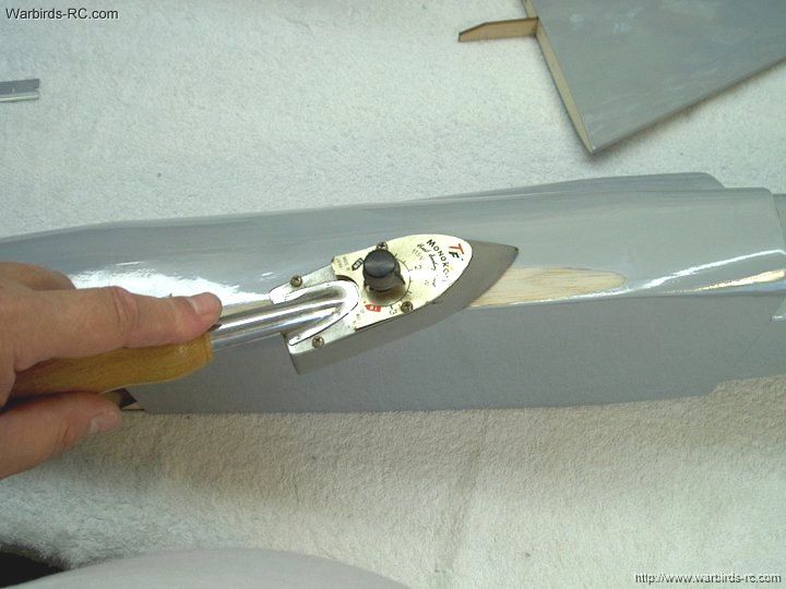
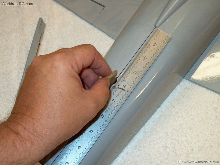
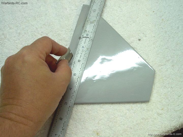
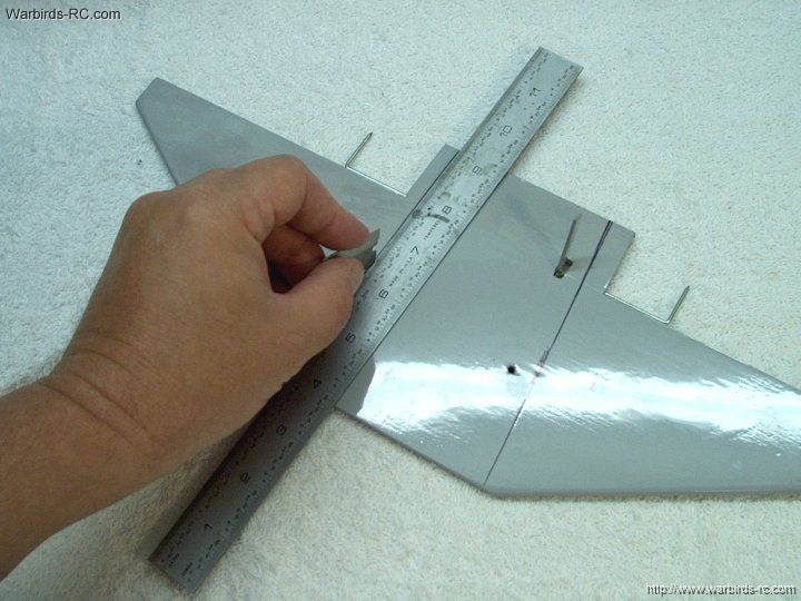
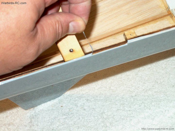
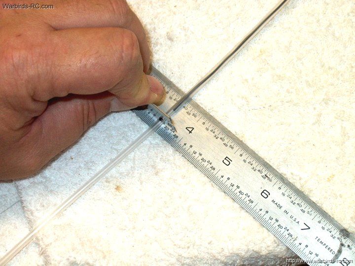
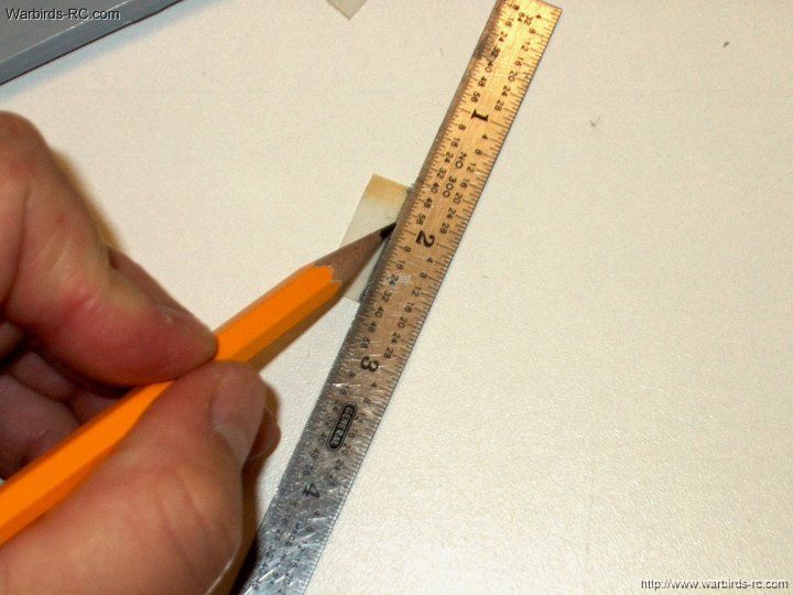
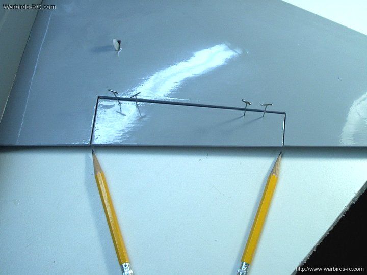
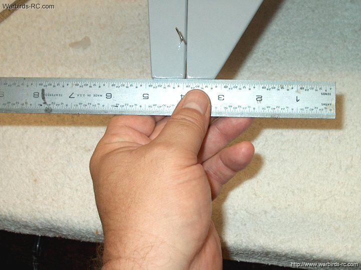
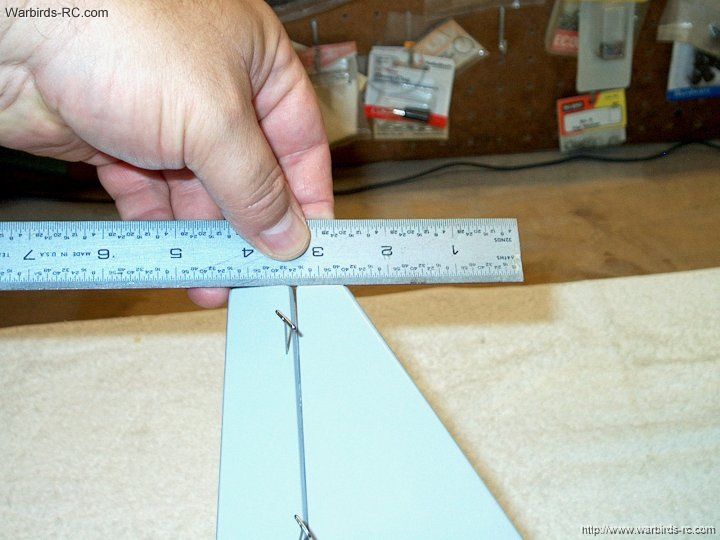
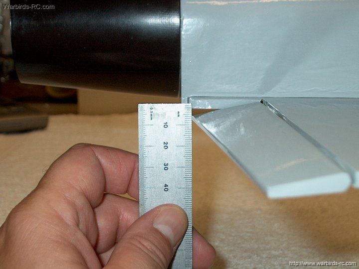
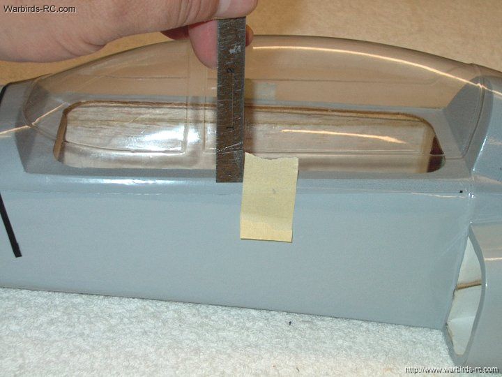
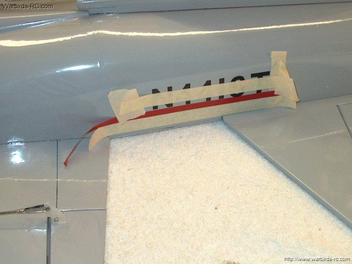
15 - Rig a ruler to measure wing position
| |
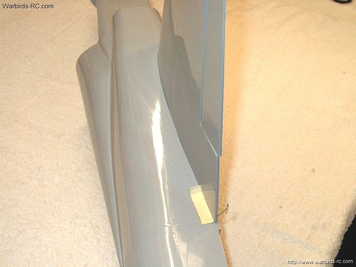
16 - Build up a piece of masking tape with
about 4-5 layers. This will be used as an anchor for the wing
root position
| |
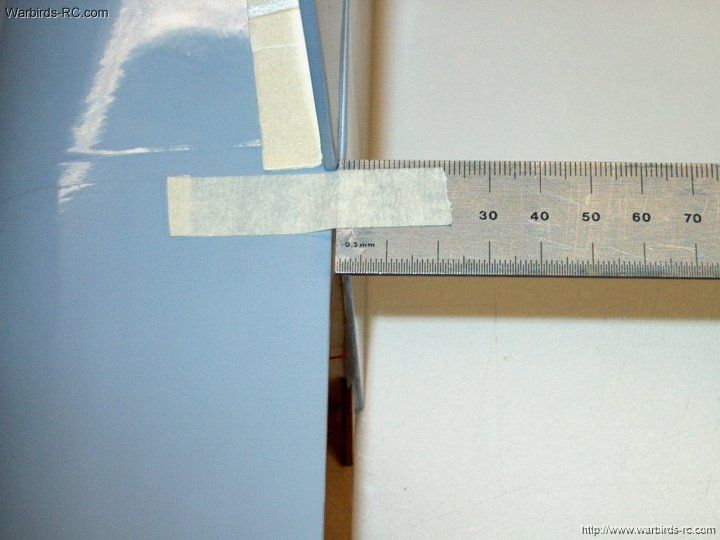
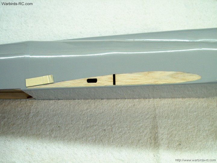
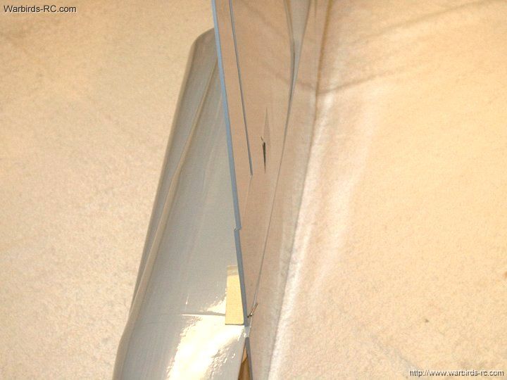
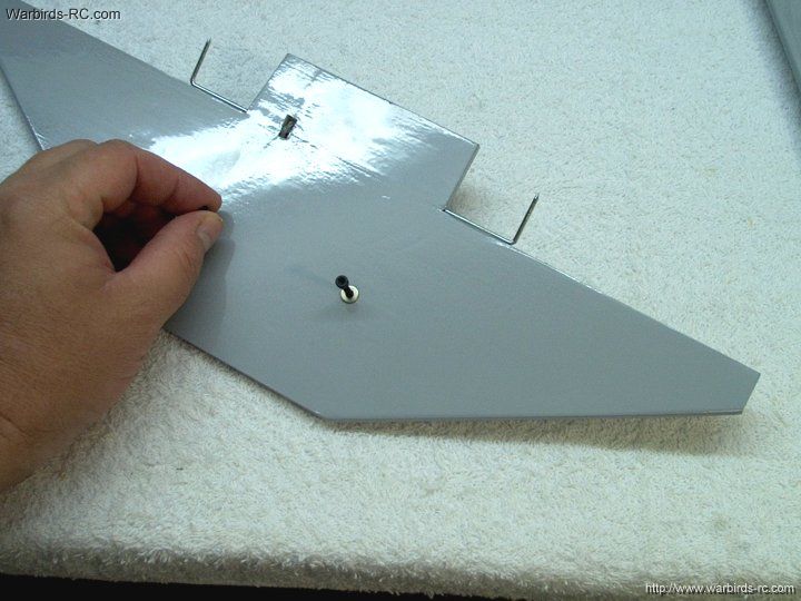
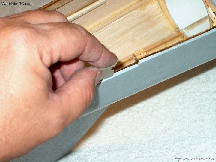
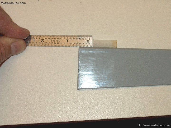
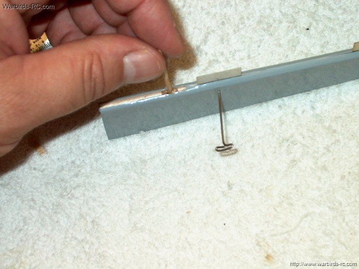
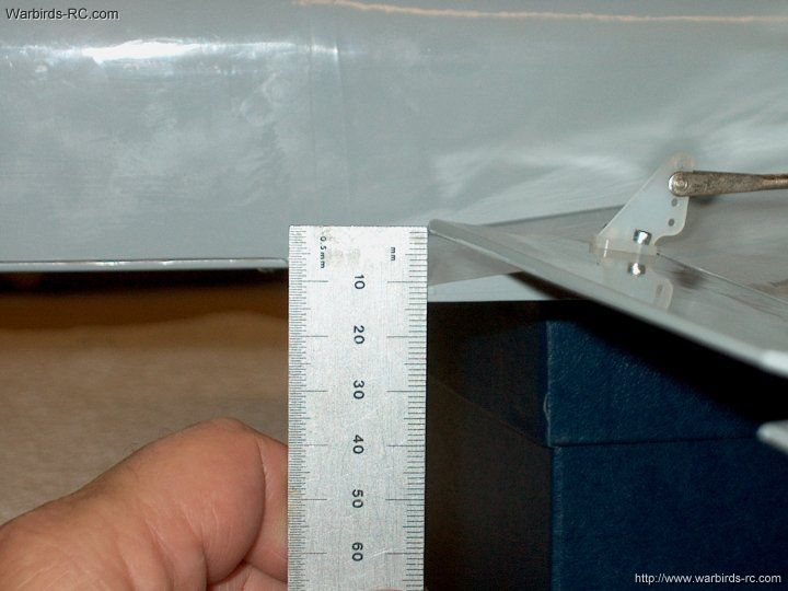
17 - The rear of wing is positioned 1MM from the
bottom of the fuselage. Place some "built up" masking tape
on the side of the fuselage to keep the wing from shifting up (left)
| |
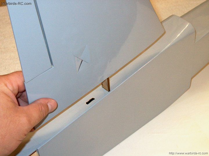
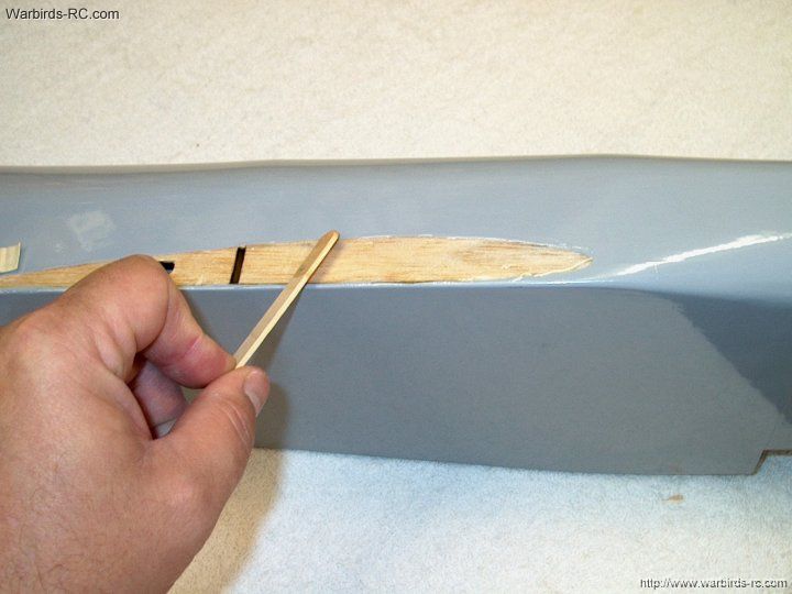
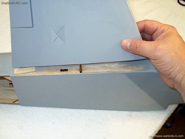
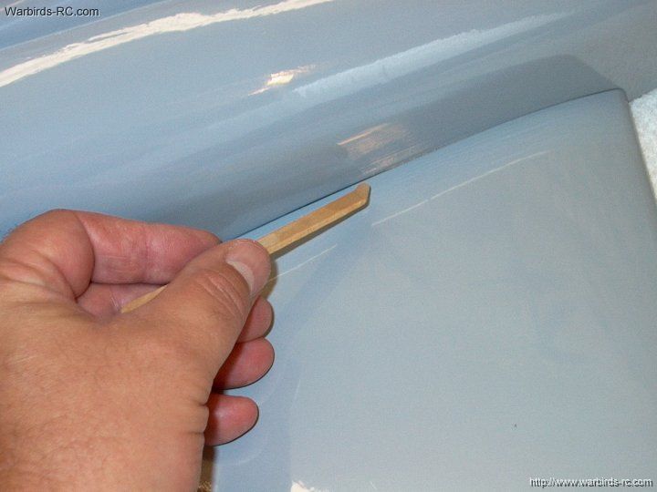
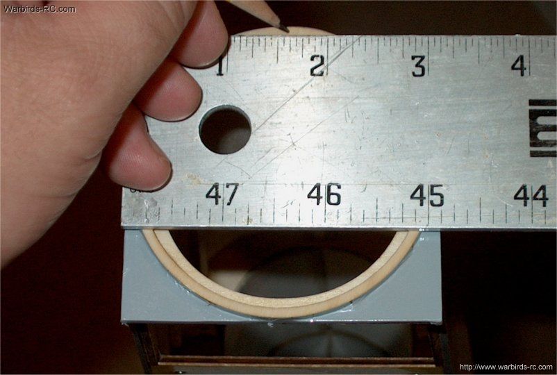
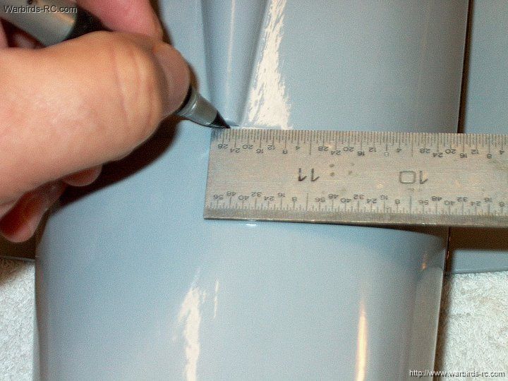
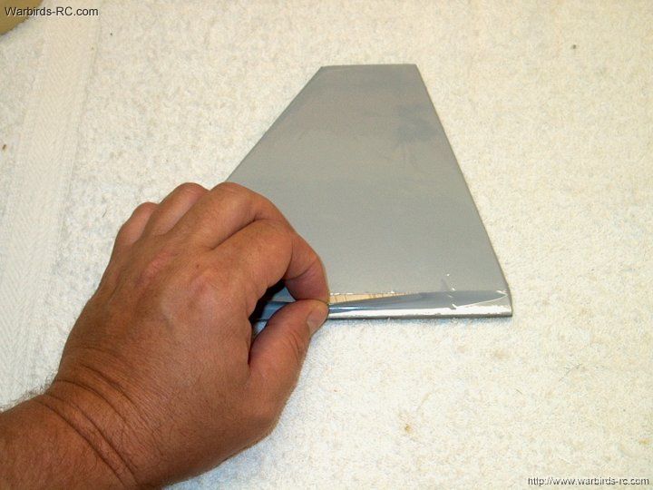
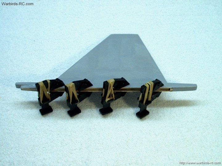
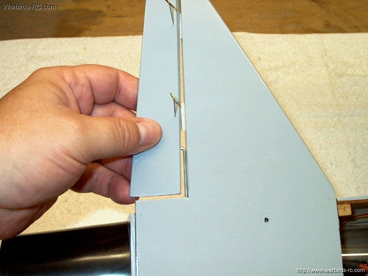
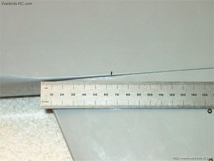
18 - The wing is supposed to be 1mm up from
the fuselage at the rear (left), then flush against the bottom where
it's chord dips (left of thumb) and then it curves upward to a
center of 10mm at leading edge
| |
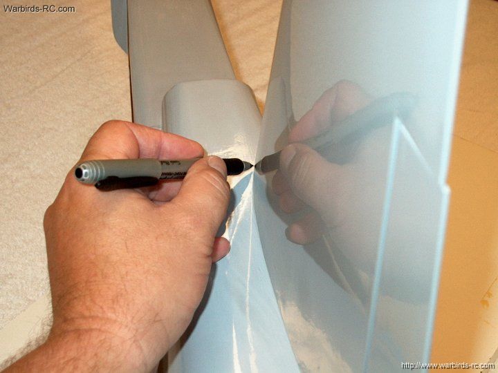
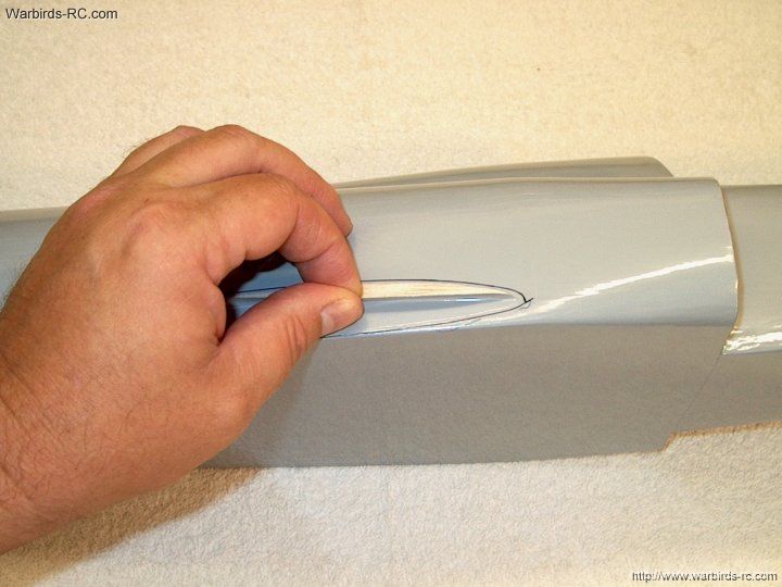
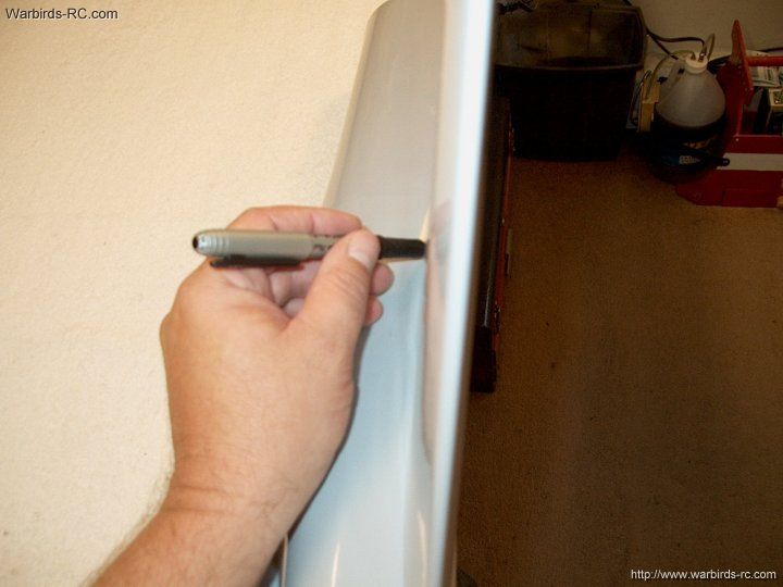
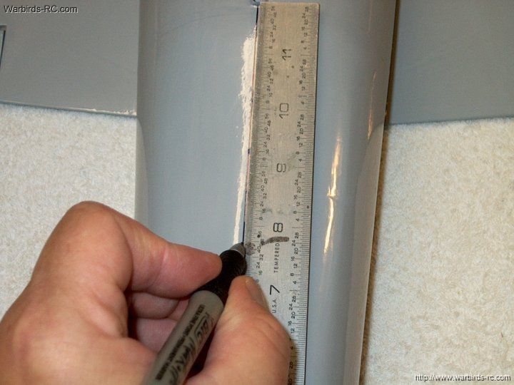
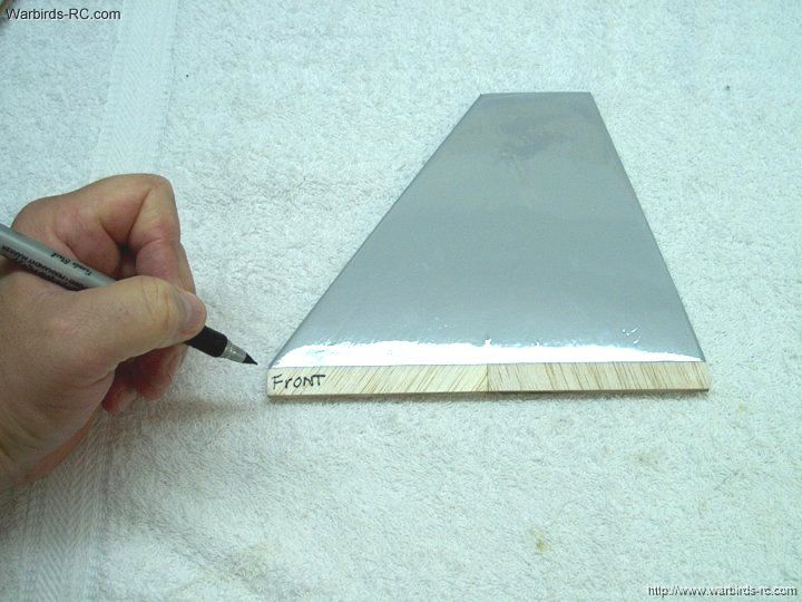
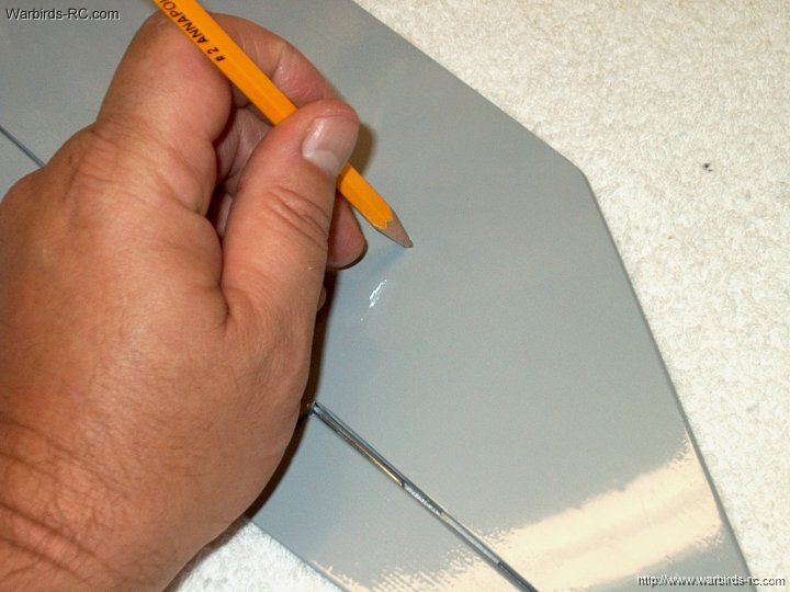
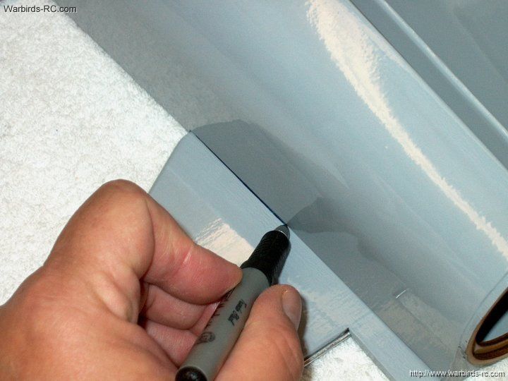
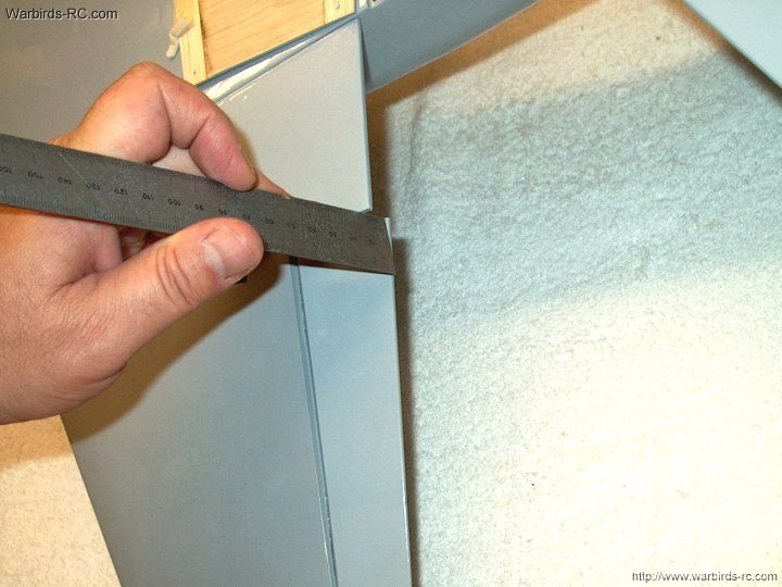
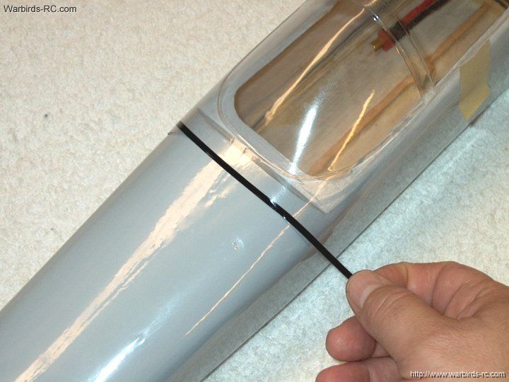
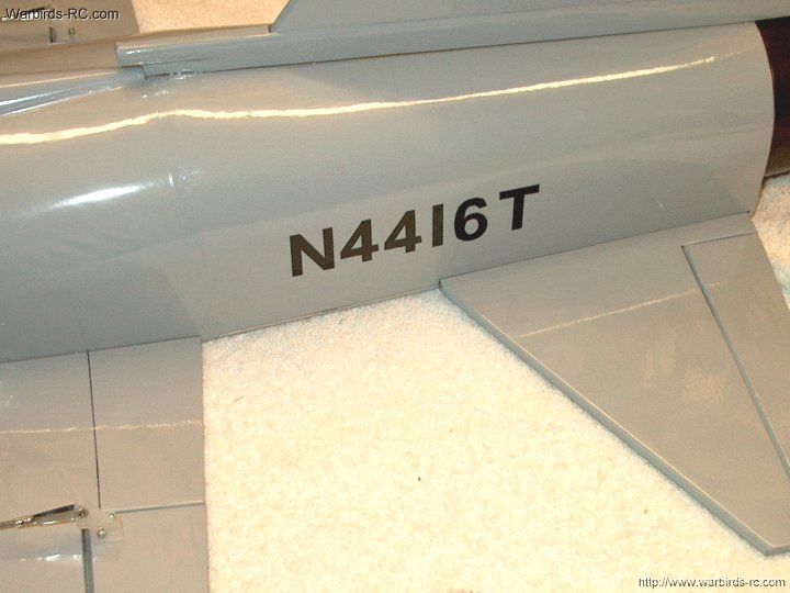
19 - Use a marker to draw the position of
the spar
| |
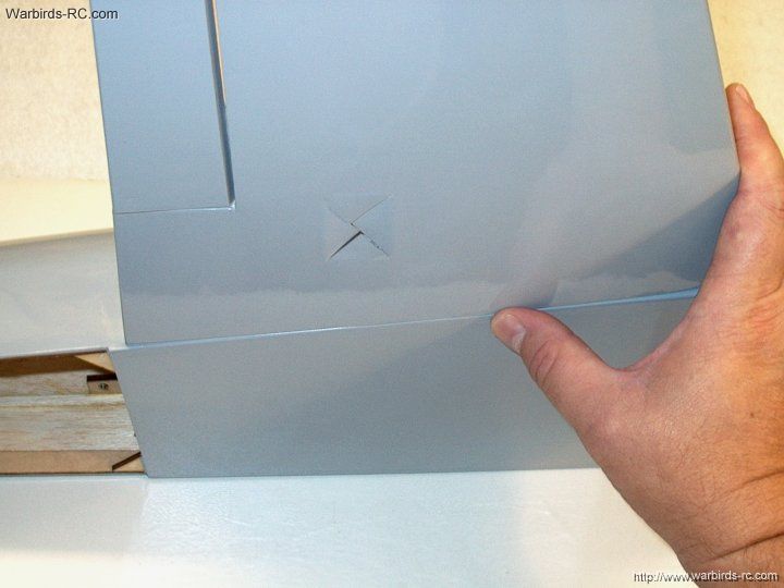
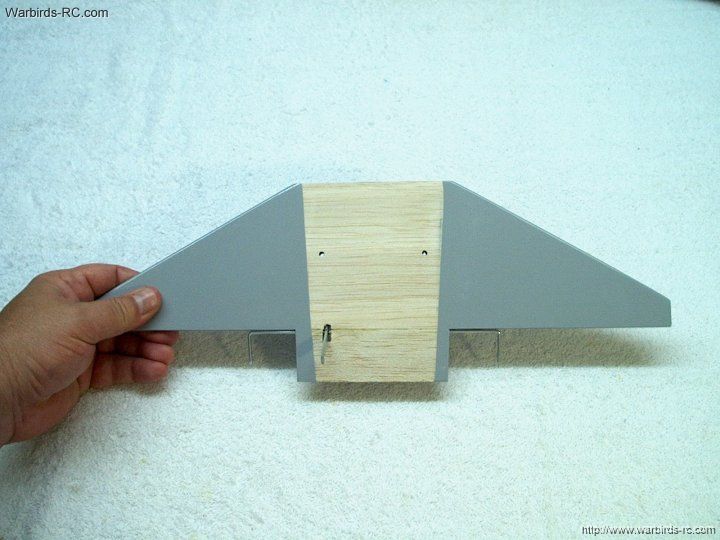
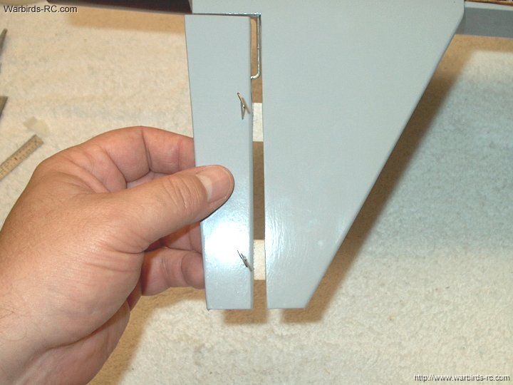
20 - Your wing position should appear
as shown
| |
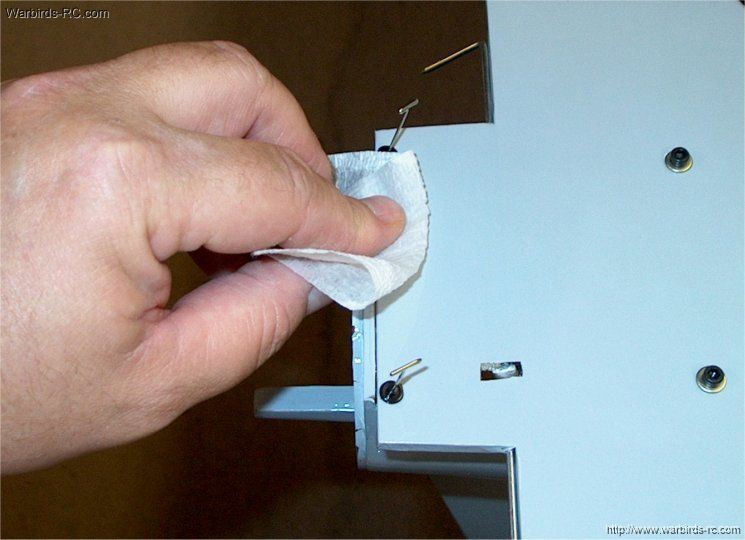
21 - Cut the covering inside the mark
so the wing can be mounted to the fuselage
| |
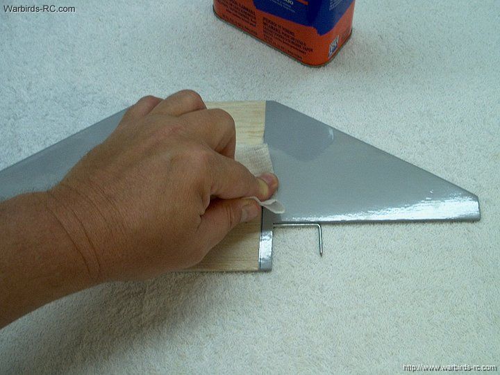
22 - Remove the covering
| |
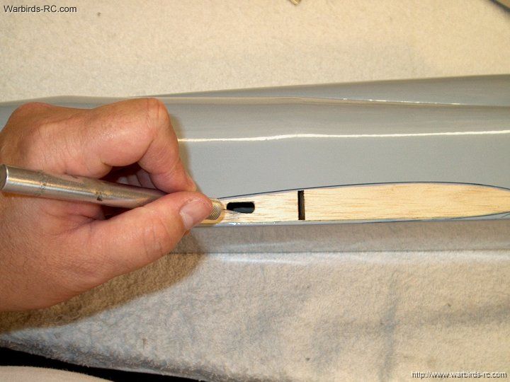
23 - Open up the aileron servo hole
| |
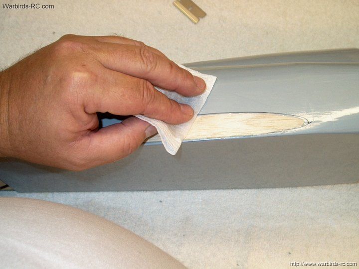
24 - Remove the marker with alcohol
| |
25 - The side should be clean and ready
for wing mounting
| |
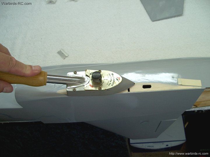
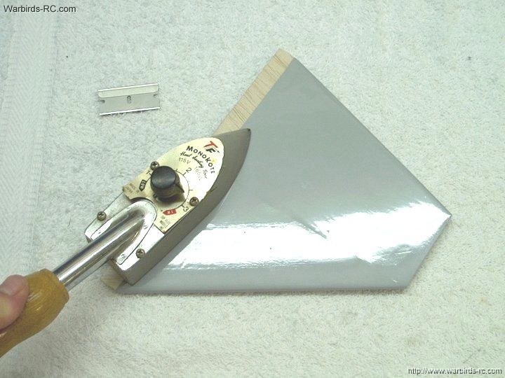
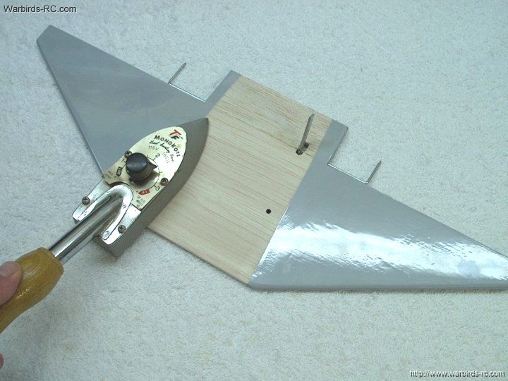
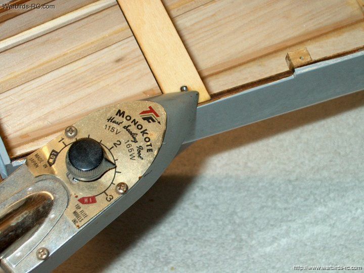
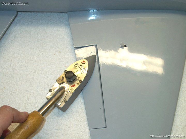
26 - Use an iron to seal the edges of
the covering
| |
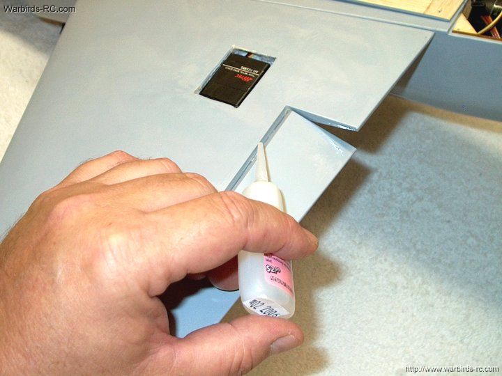
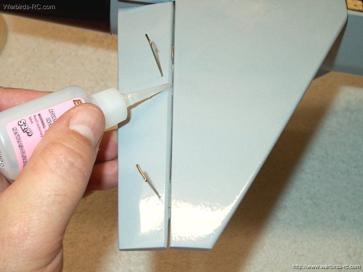
27 - Apply epoxy to the exposed area and
wing spar slotted hole
| |
28 - Apply epoxy to the wing root and spar.
Note that due to the much wider wing chord, holes need not be
drilled in the wing
| |
29 - Install the wing on the fuselage
| |
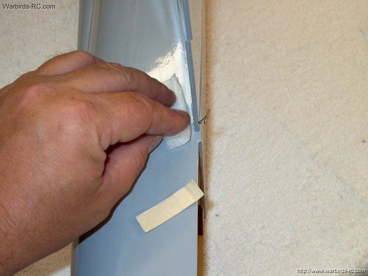
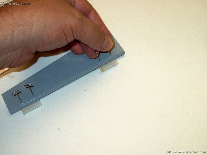
30 - Pin the rear of the wing to hold the
position at 1mm from the bottom and hold it up against the
masking tape jig. Also note the wing is flush to the bottom
of the fuselage near the center. Leave it like this until
the epoxy cures.
| |
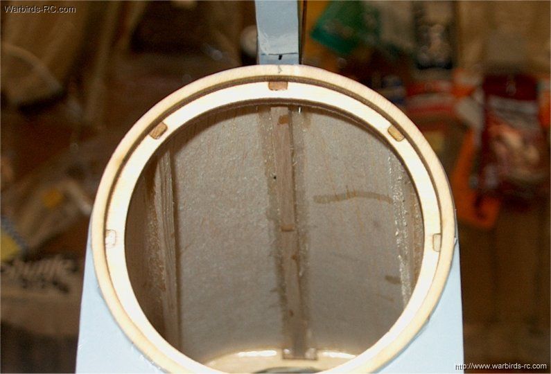
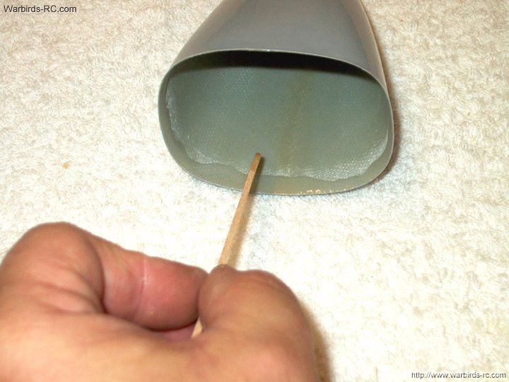
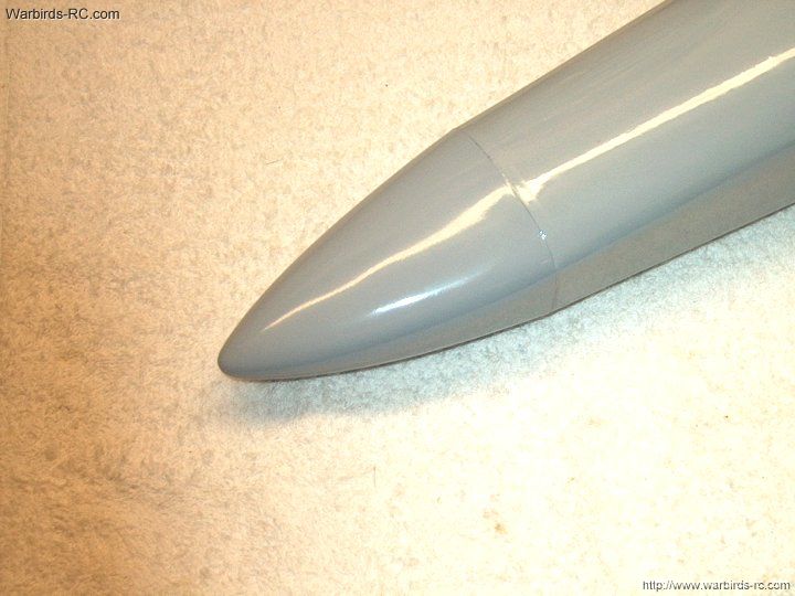
31 - Install the wing. The wing
has a slight dihedral, so it is ok if it seems to lean
slightly upward
| |
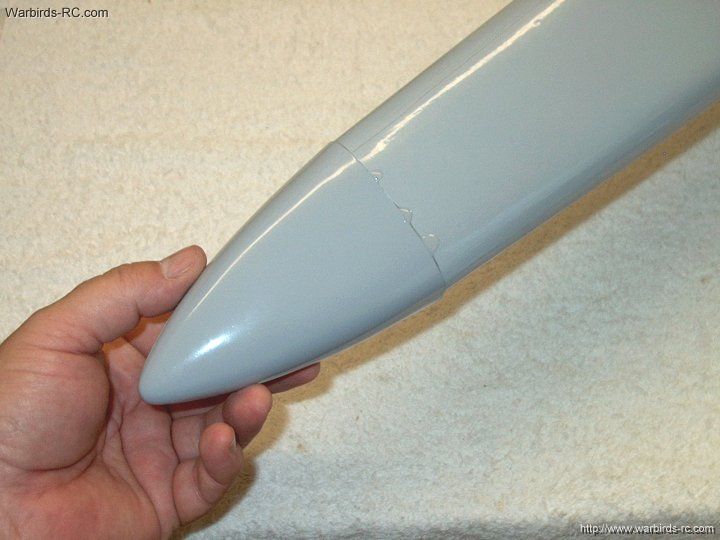
32 - Remove excess epoxy with alcohol
before it sets
| |
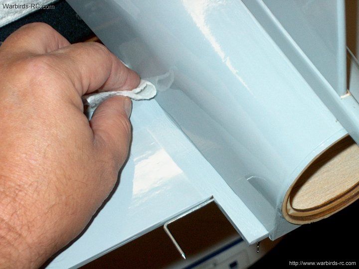
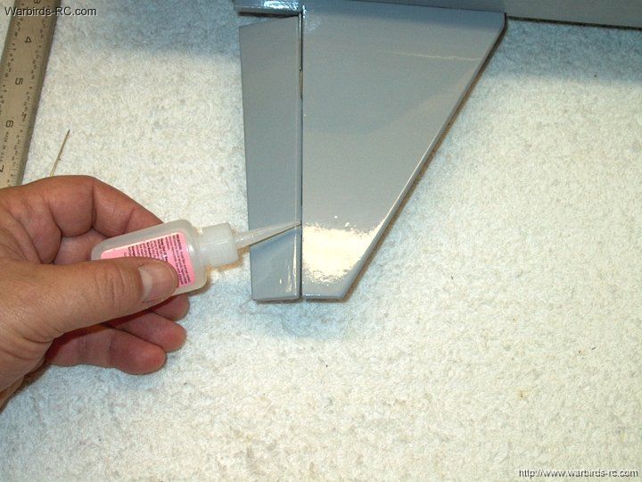
33 - Once the wing set, use extra epoxy
to fill any small gaps. Remove the excess with a paper towel
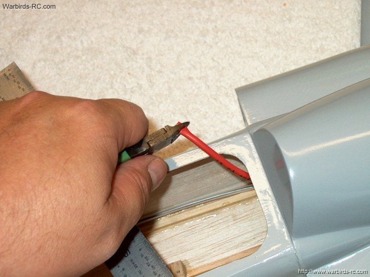
dampened in alcohol
| |
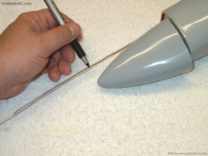
34 - Position the other wing and mark
the chord
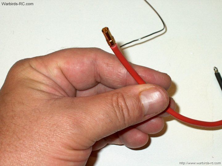
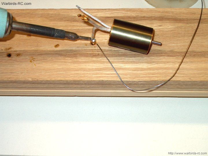
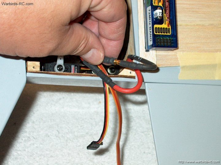
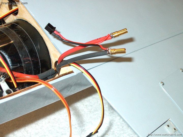
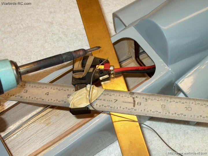
| |
35 - Remove the excess covering
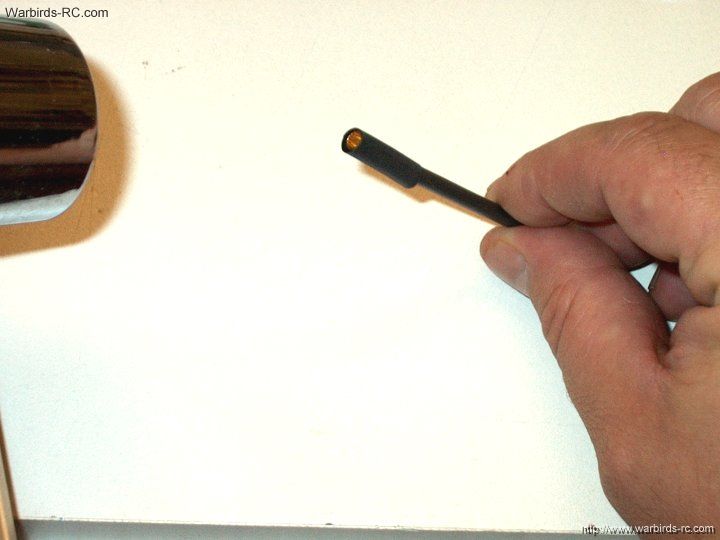
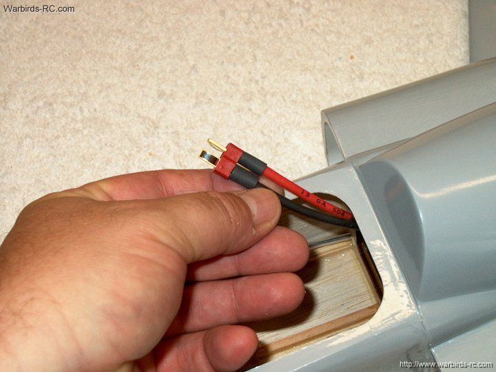
| |
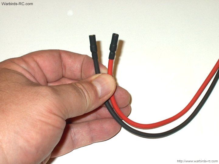
36 - Open up the aileron wire hole and iron
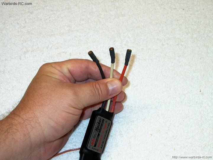
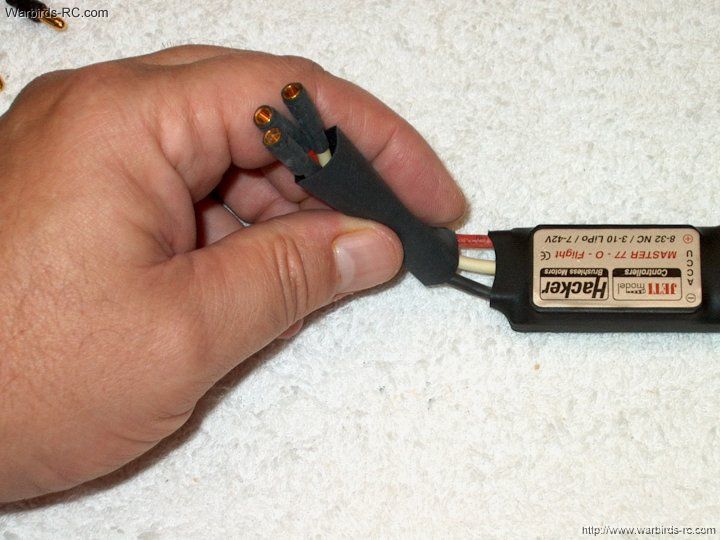
the edges
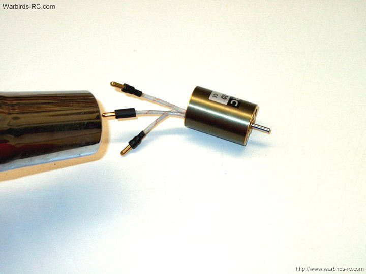
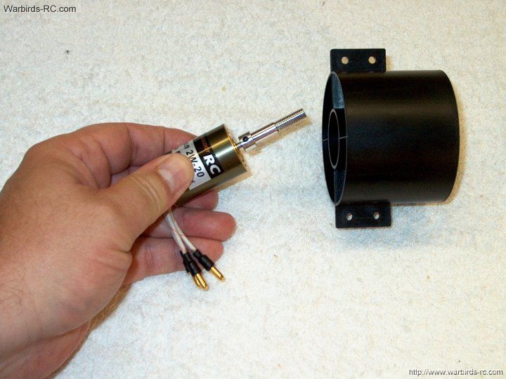
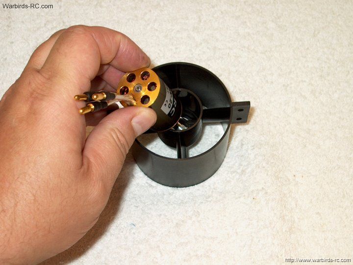
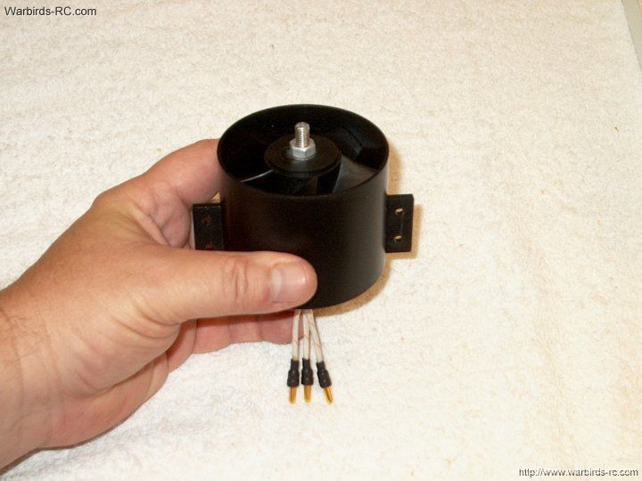
| |
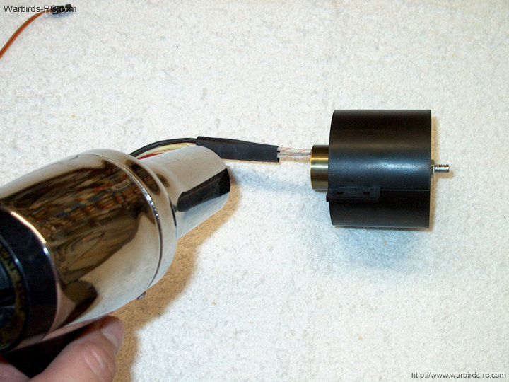
37 - Apply epoxy to the wing saddle on
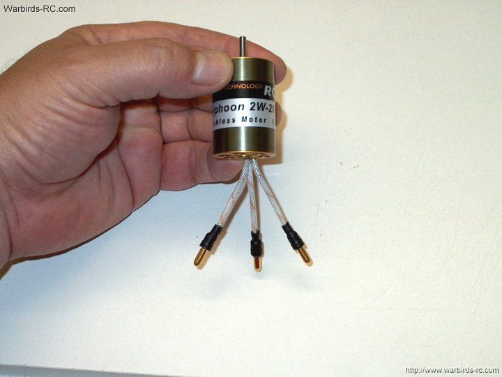
the fuselage, as well as the spar
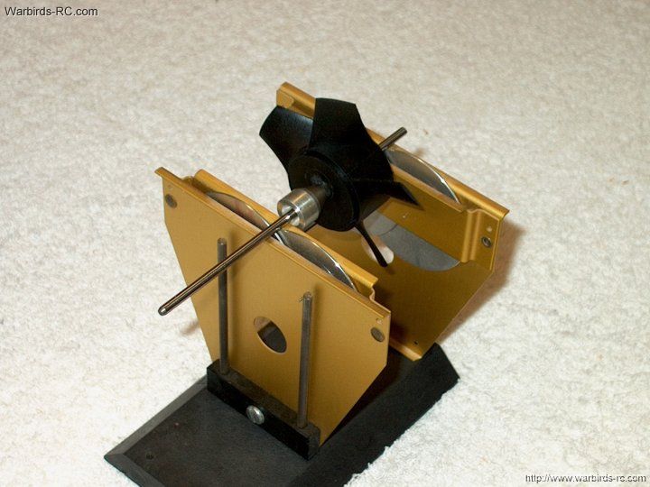
| |
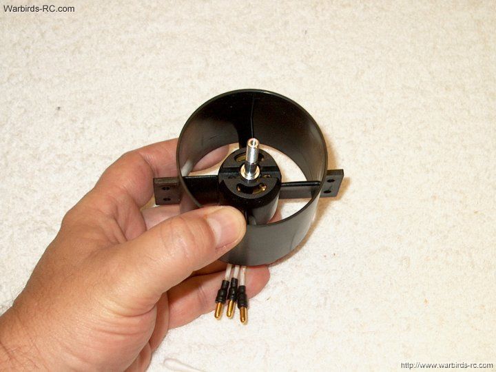
38 - Pin the rear of the wing to hold the
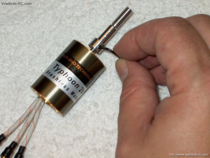
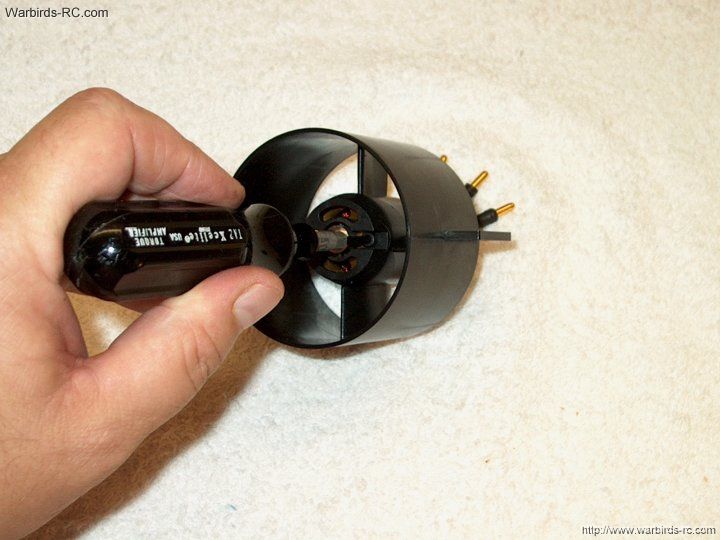
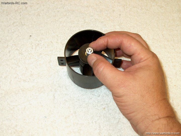
position at 1mm from the bottom and hold it up against the
masking tape jig. Also note the wing is flush to the bottom
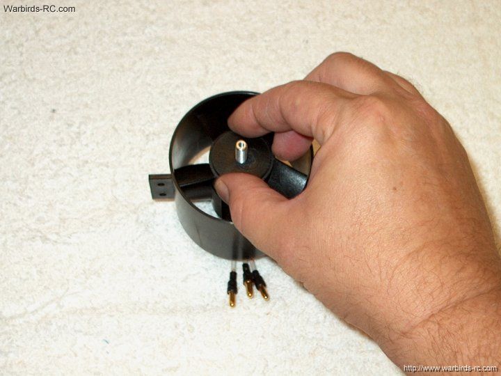
of the fuselage near the center. Leave it like this until
the epoxy cures.
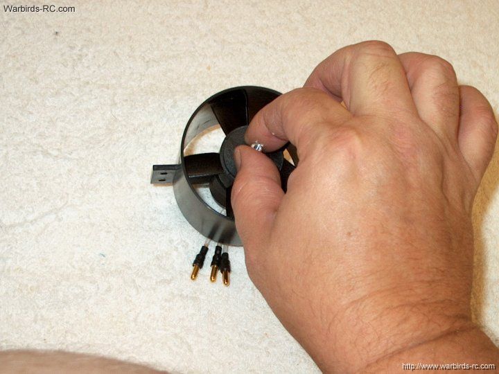
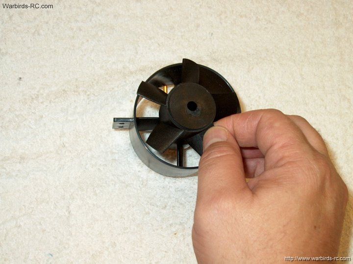
| |
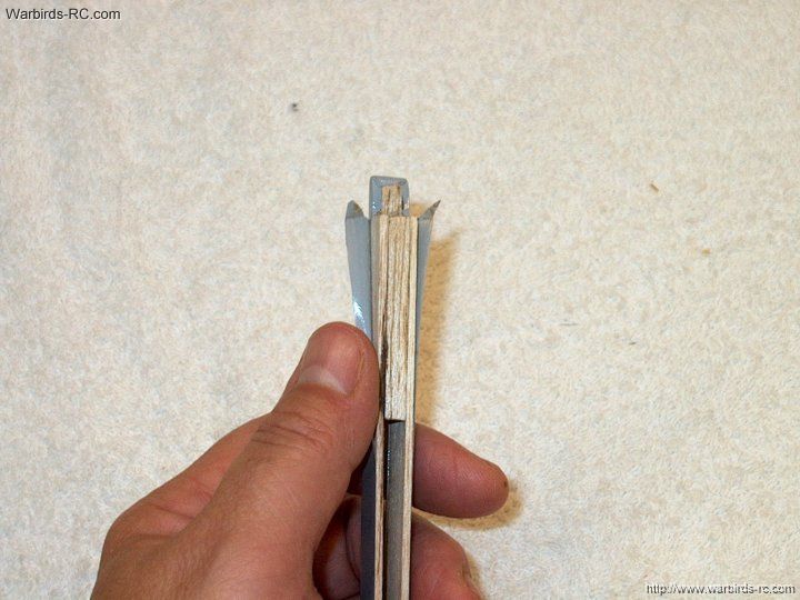
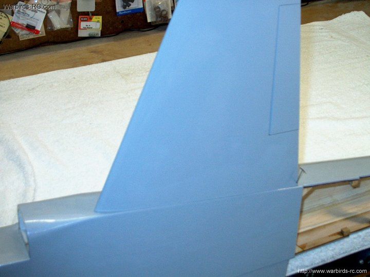
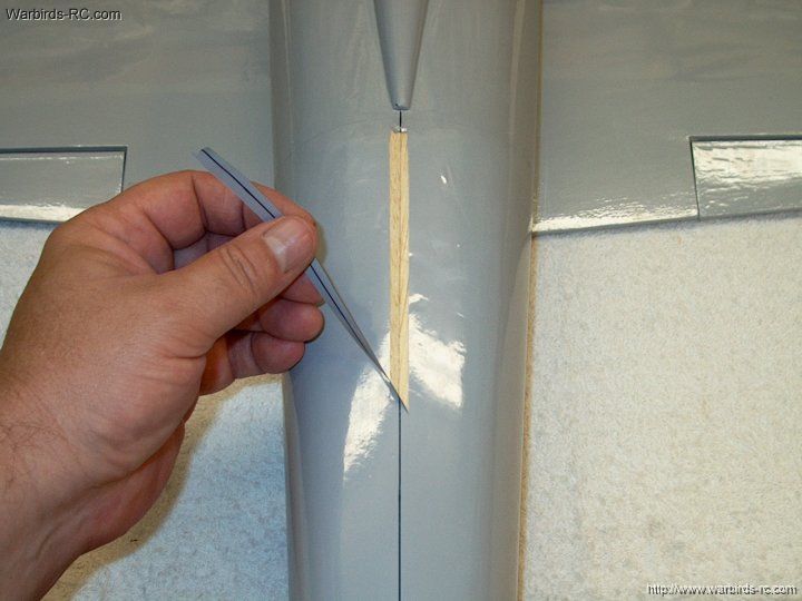
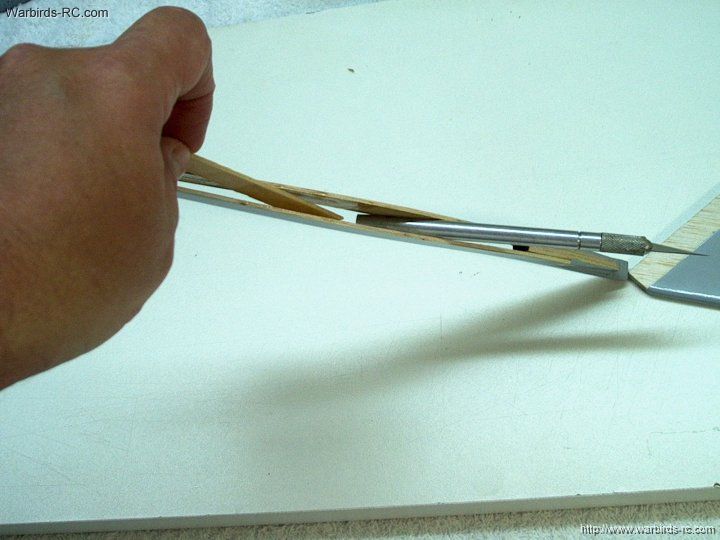
39 - The vertical Stab spar was not
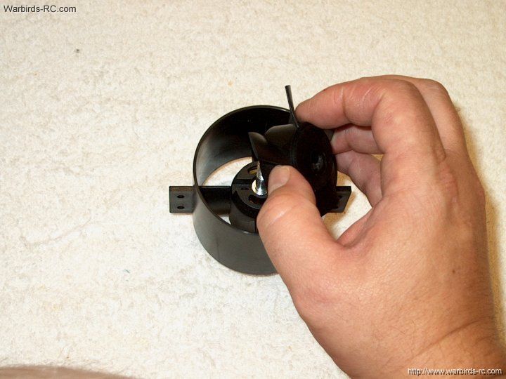
shaped correctly, so trim it to a taper at the forward
section. TIP: you can re-use old pieces of covering removed
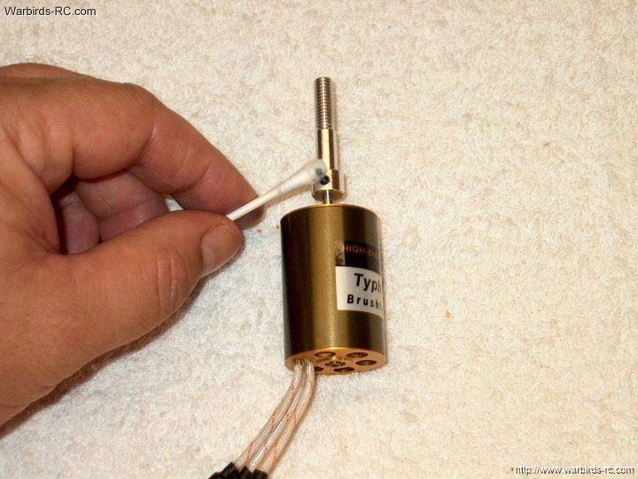
from wing chord to cover the re-shaped areas
| |
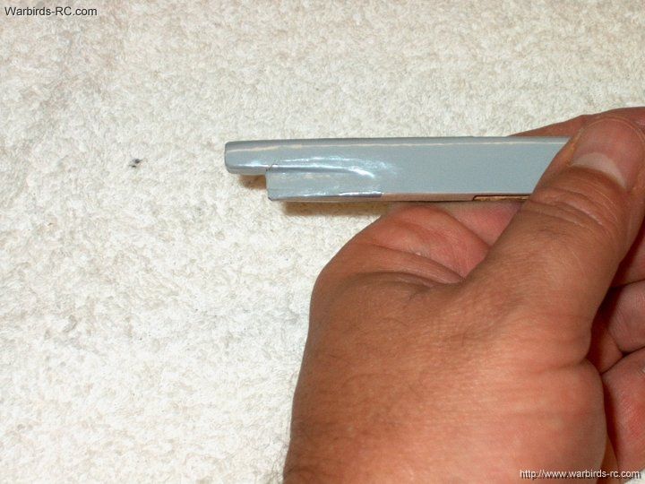
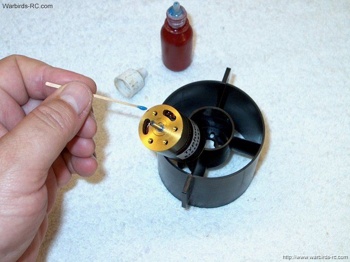
40 - The stab spar is shaped as shown
| |
41 - Mark the top of the fuselage for
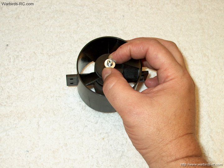
vertical stab installation
| |
42 - The mark should appear as shown
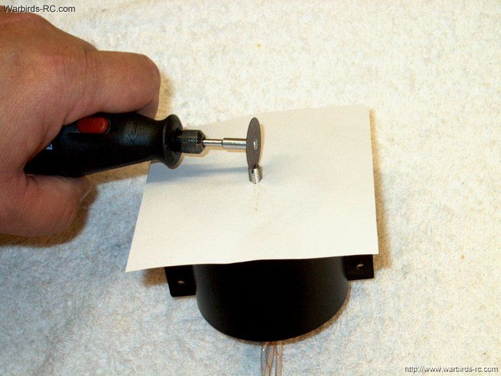
| |
43 - Mark the forward section of the
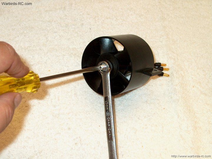
fuselage at the center of the turtle deck
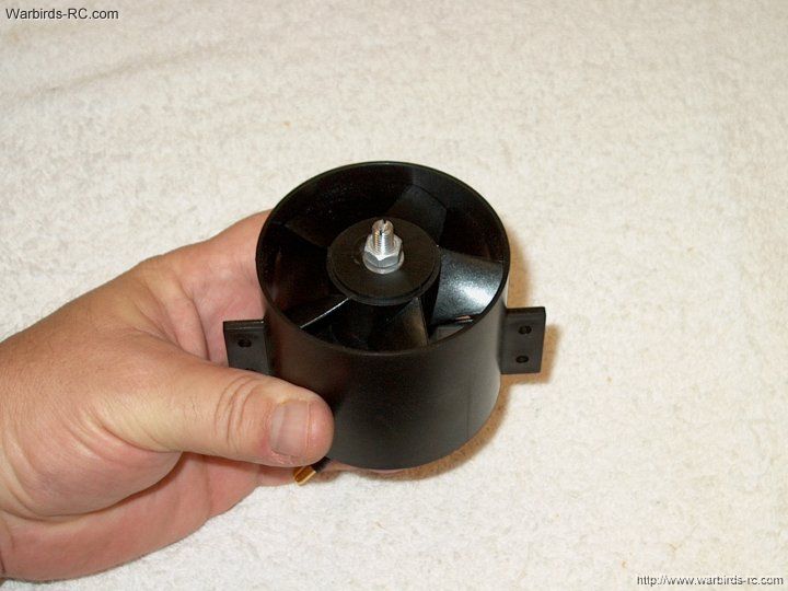
| |
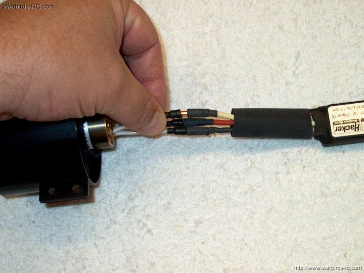
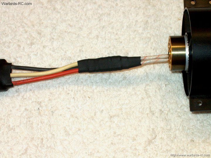
44 - Draw a line from the turtle deck
mark to the rear mark on the fuselage
| |
45 - Your center line should appear as shown
| |
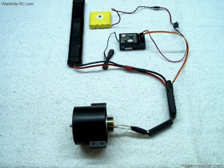
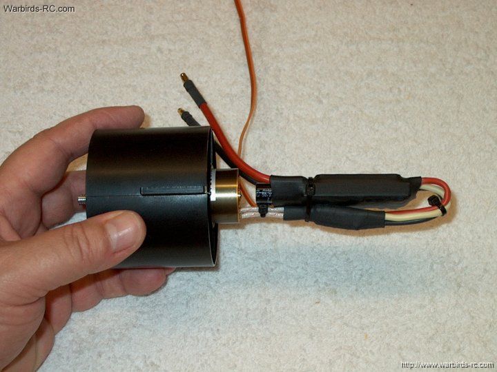
46 - Cut the covering about 1/8" wide
on each side of the center line
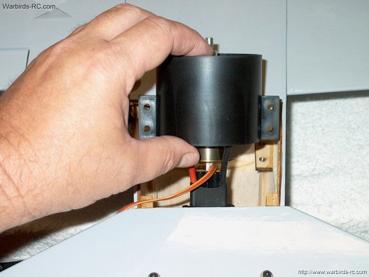
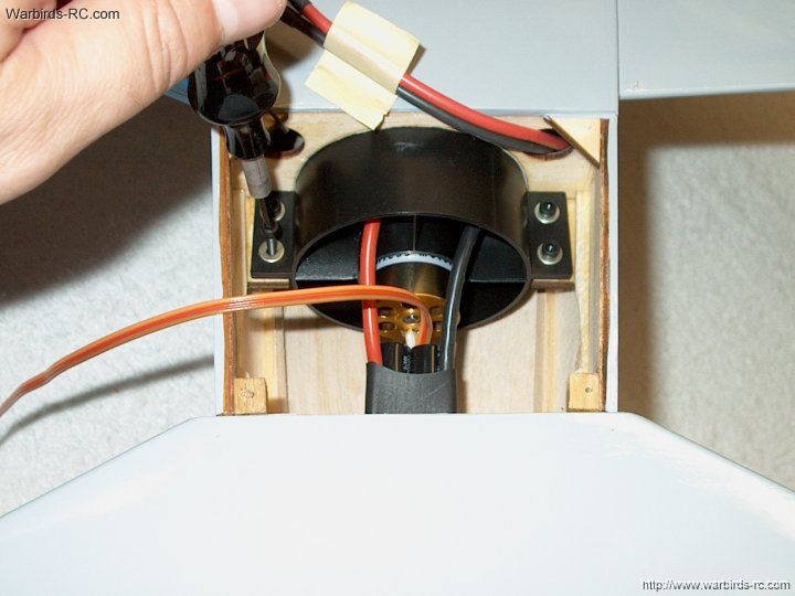
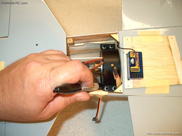
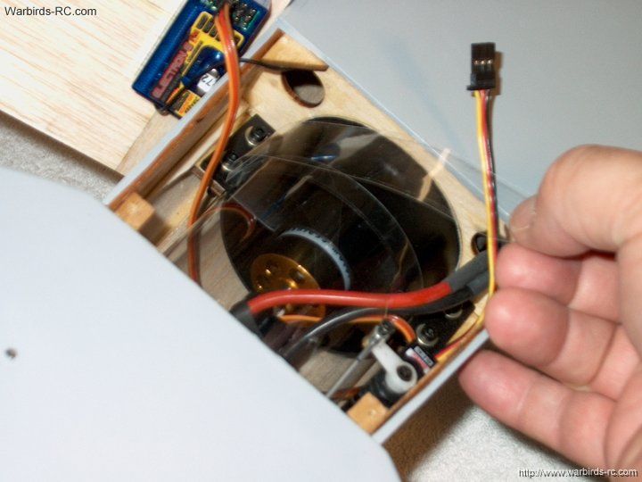
| |
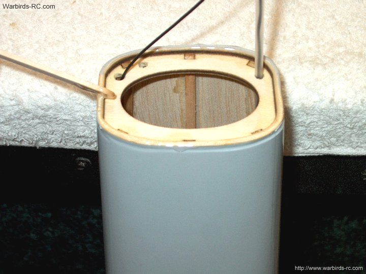
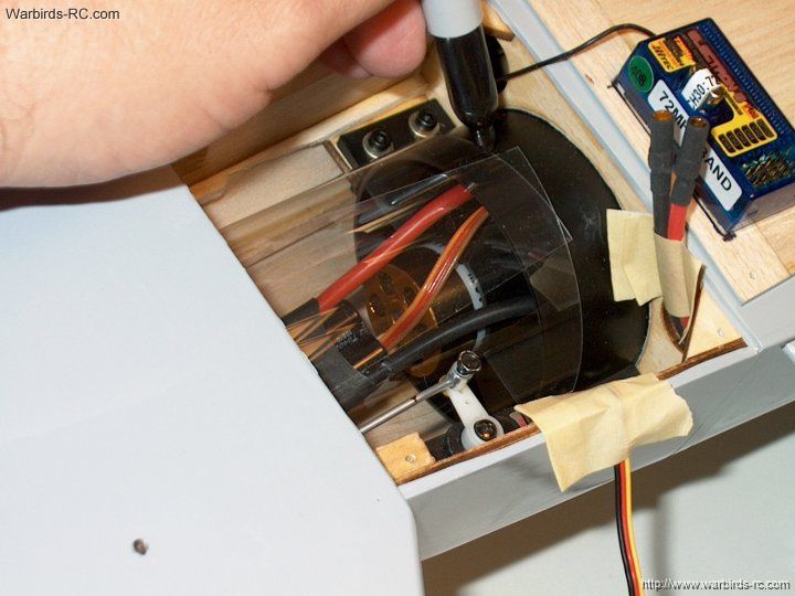
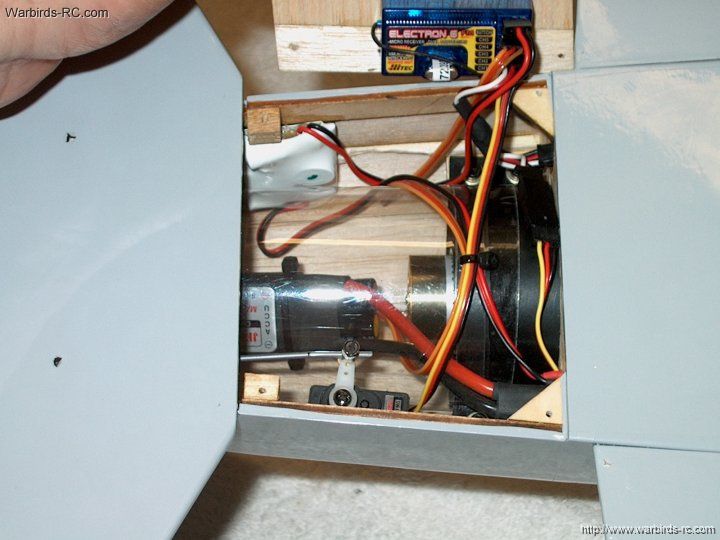
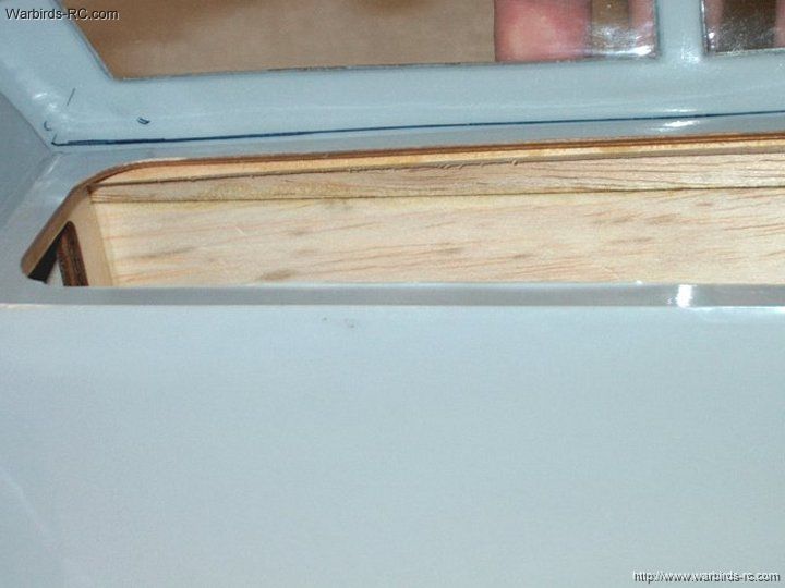
47 - Remove the covering
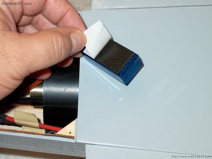
| |
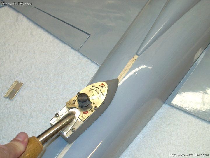
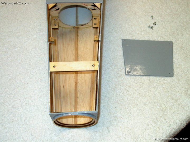
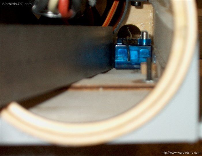
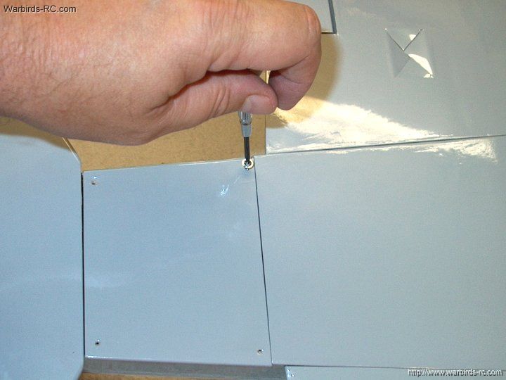
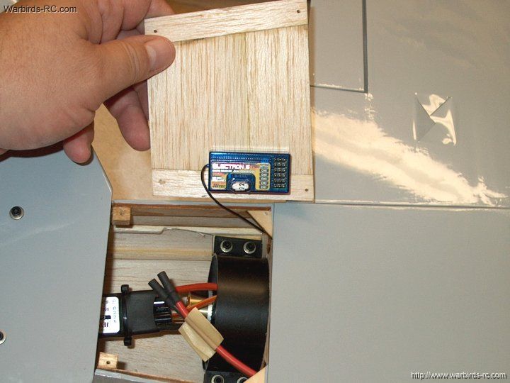
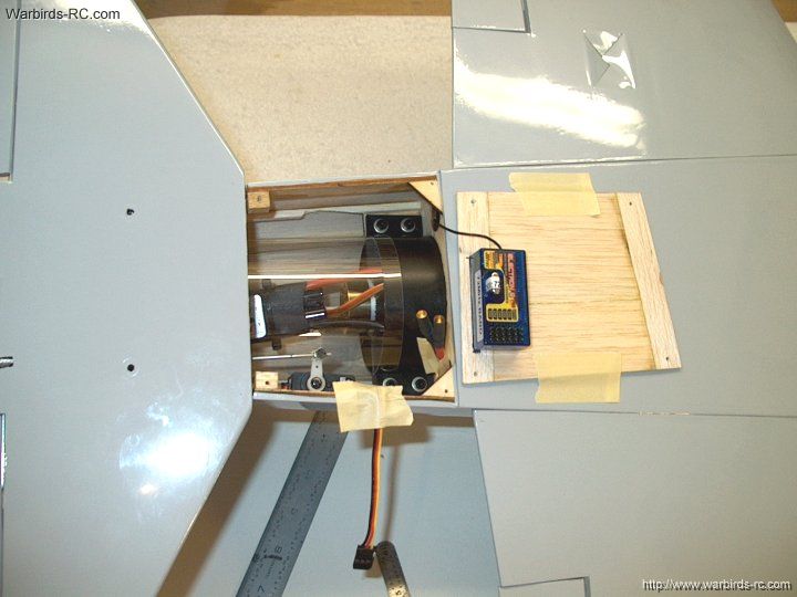
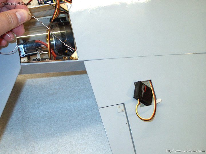
48 - Use an iron to seal the edges
| |
49 - Trim the stab covering 1/2" from
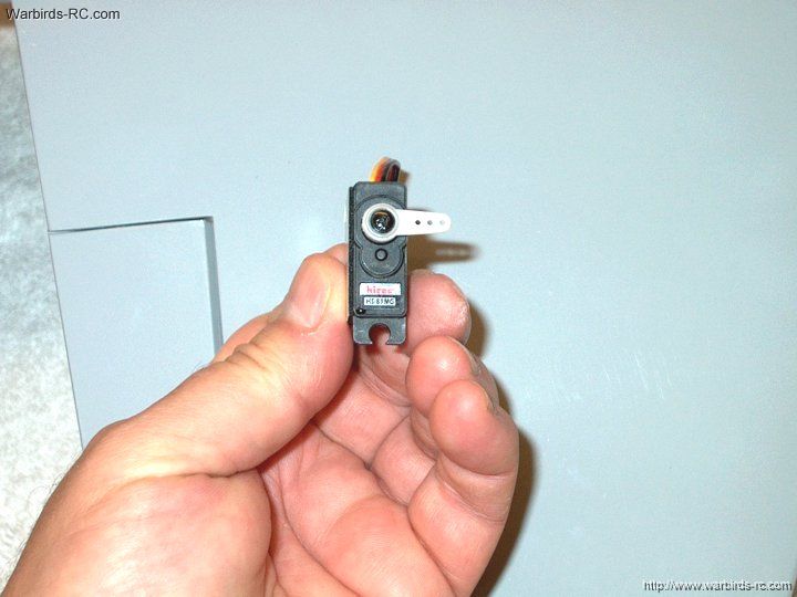
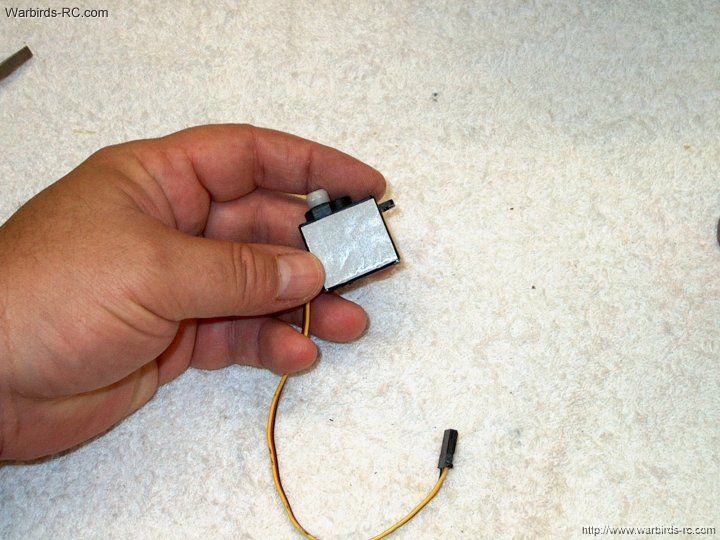
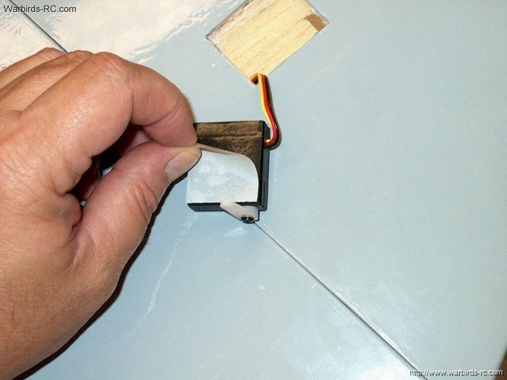
the bottom of the stab
| |
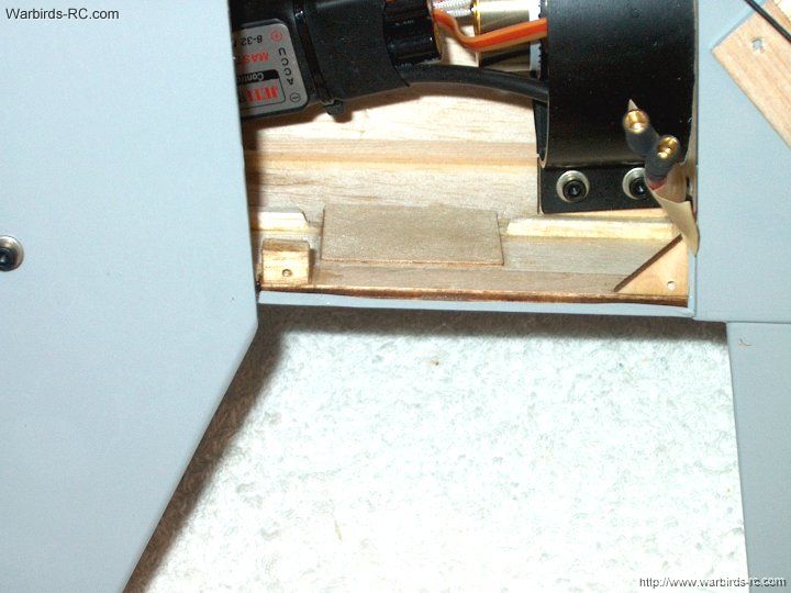
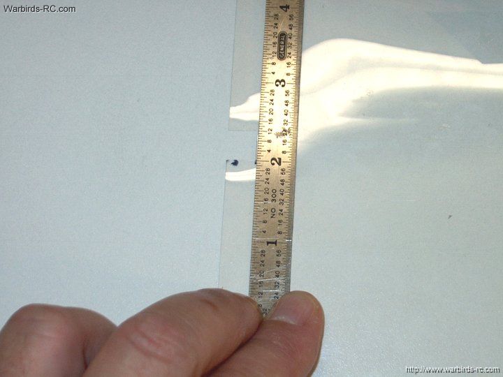
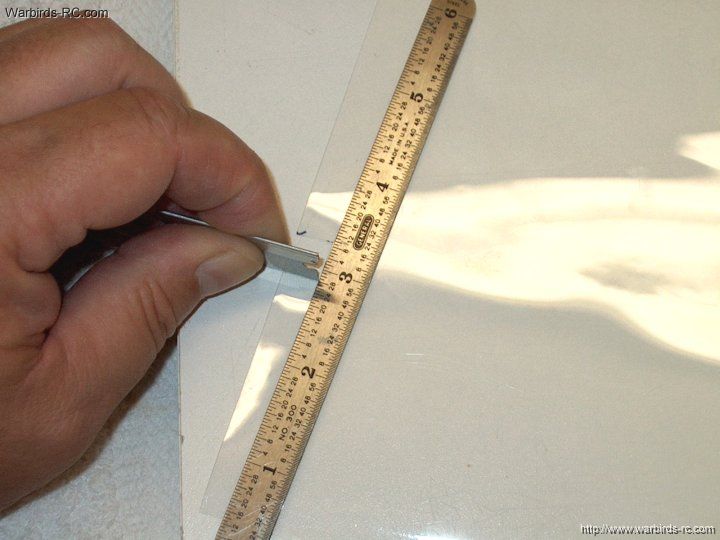
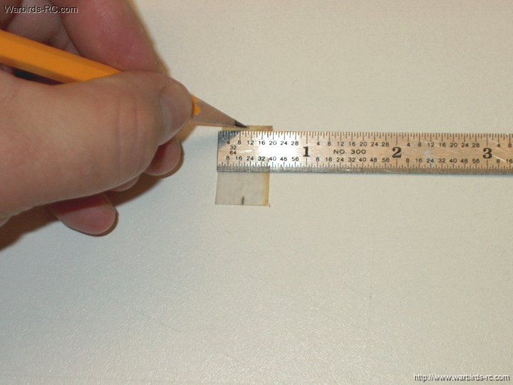
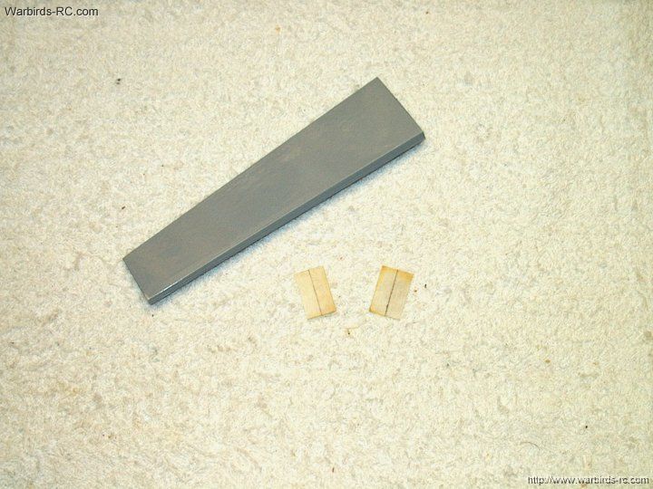
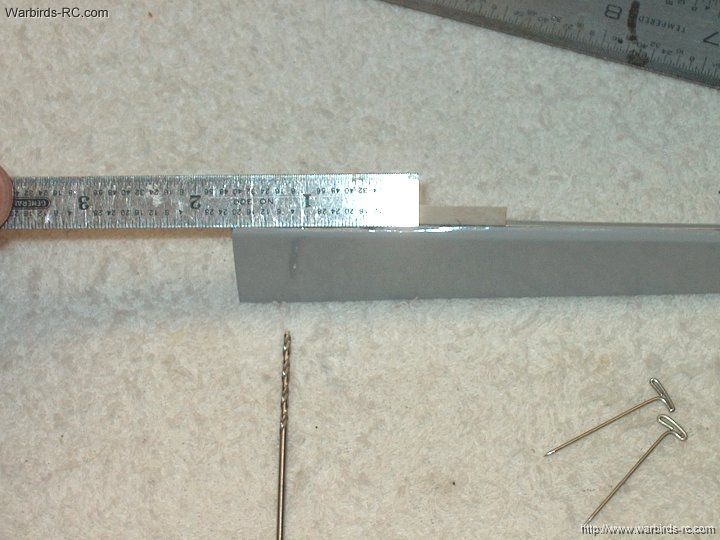
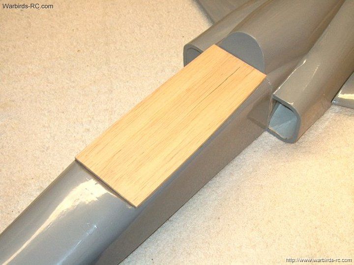
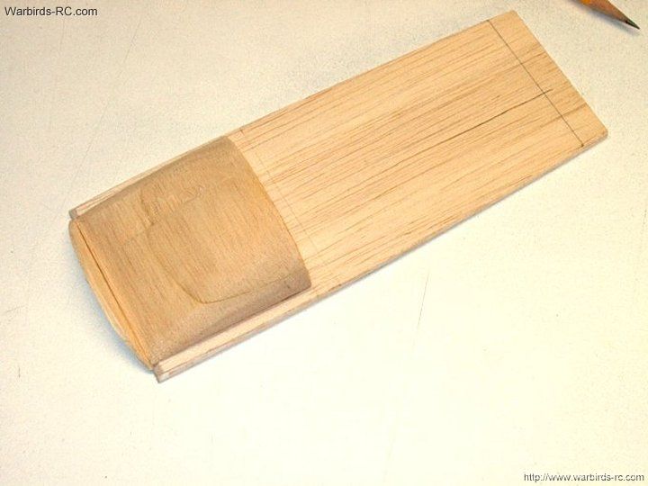
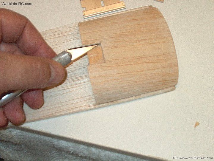
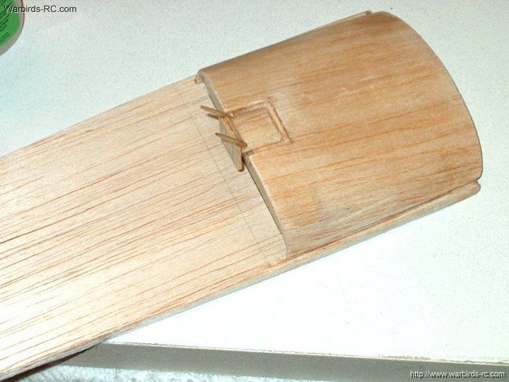
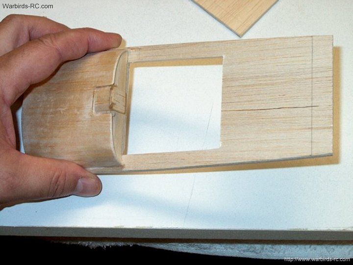
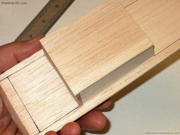
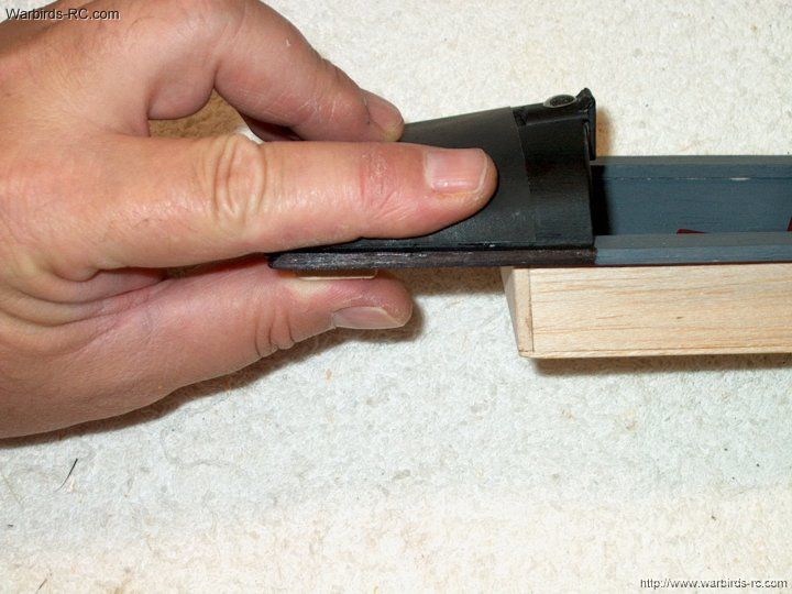
50 - Remove the covering
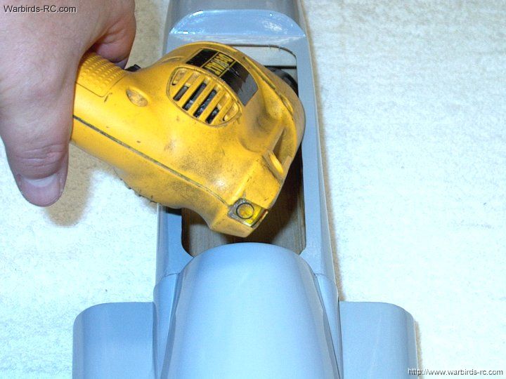
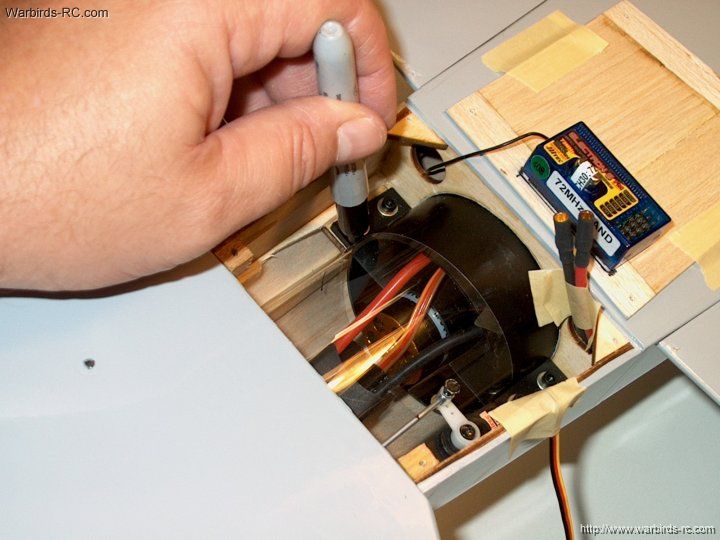
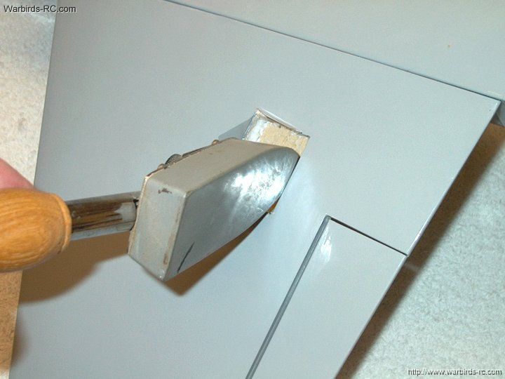
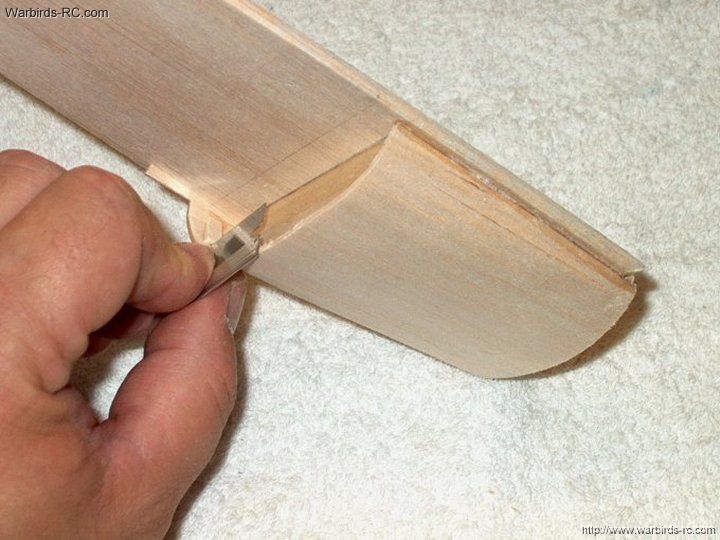
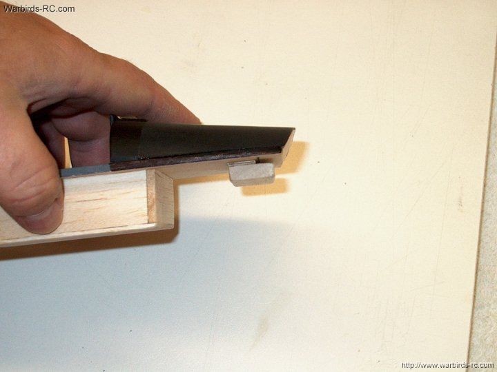
| |
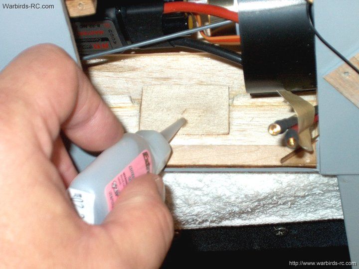
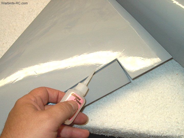
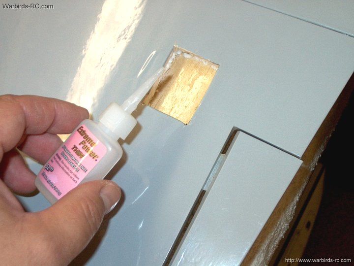
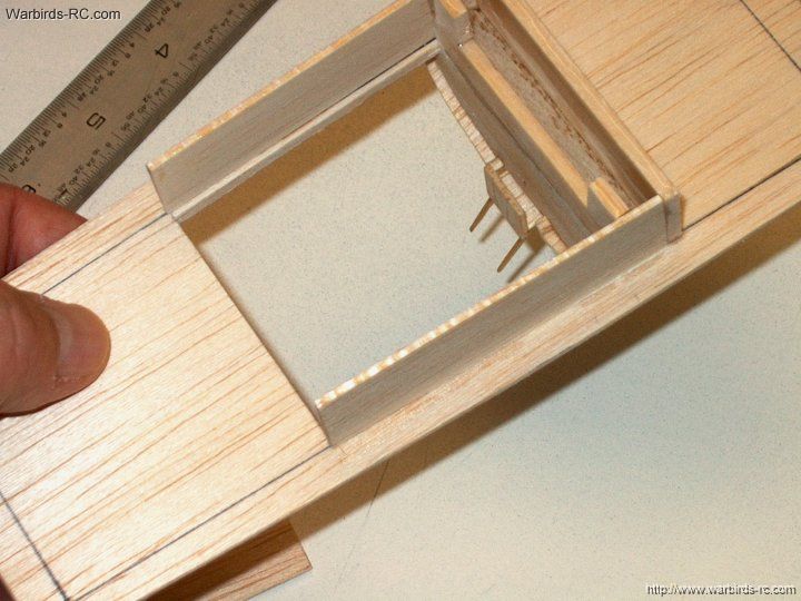
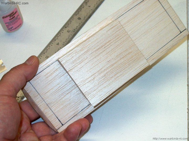
51 - Seal the edges of the covering with an iron
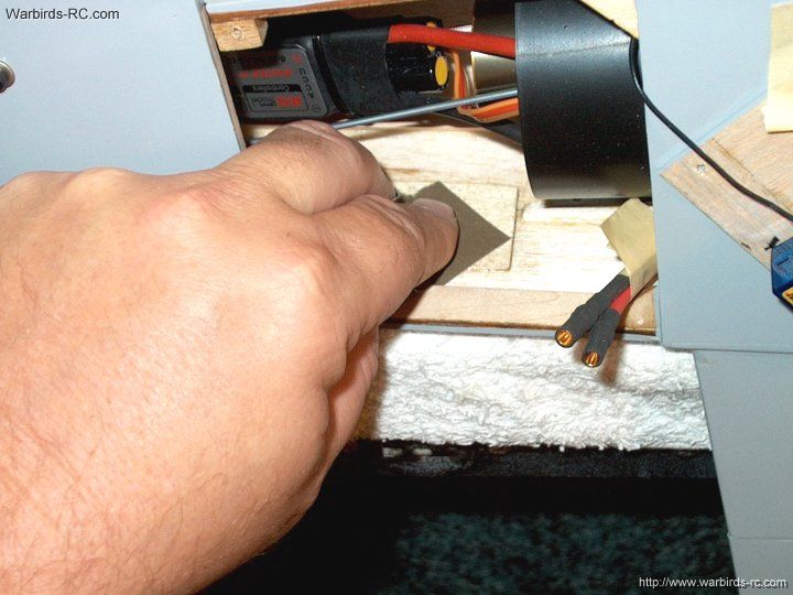
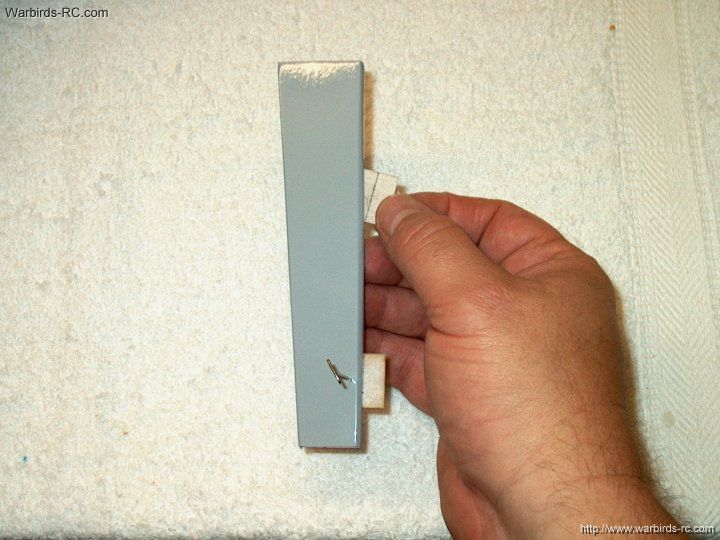
| |
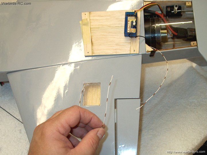
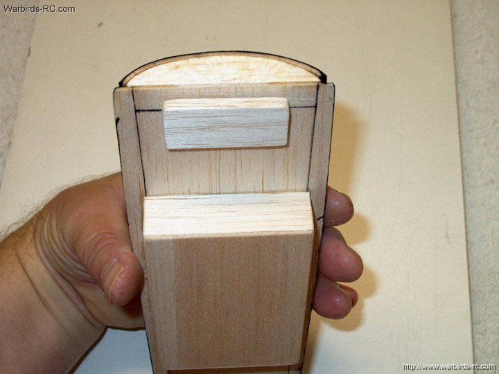
52 - Mark the front of the stab so it is
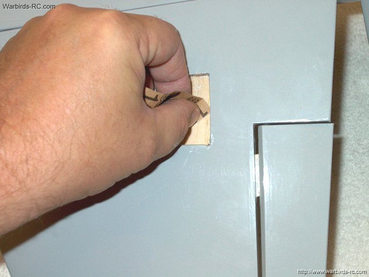
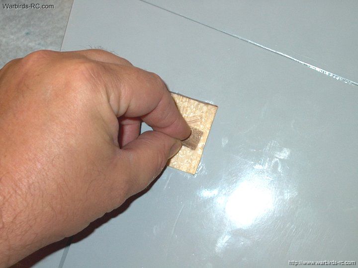
installed in the proper direction
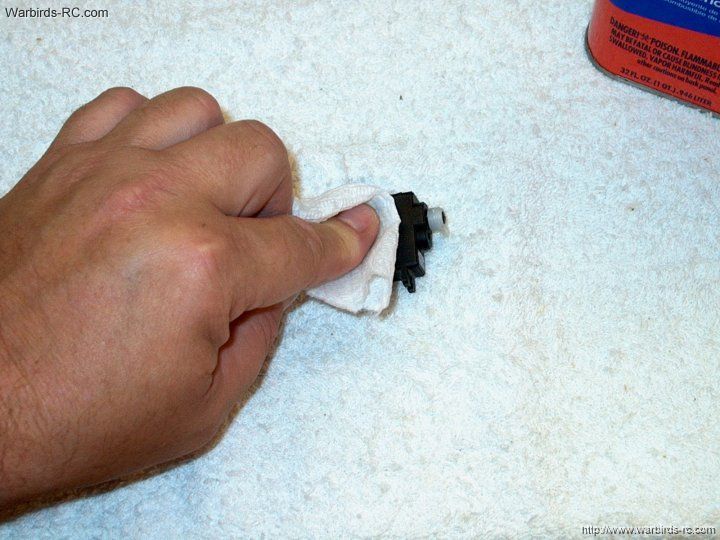
| |
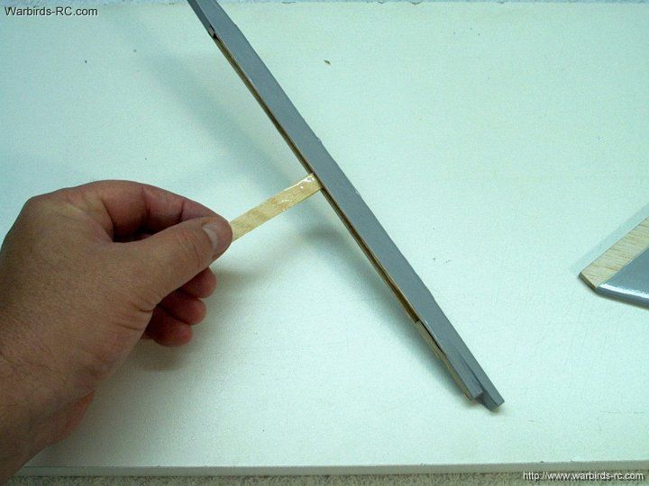
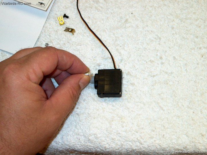
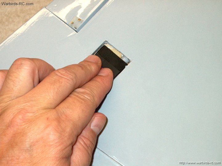
53 - Test fit the stab in the stake
| |
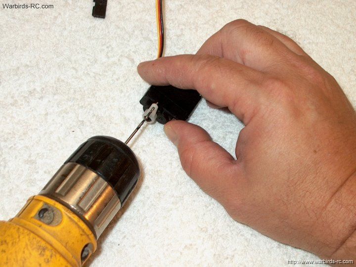
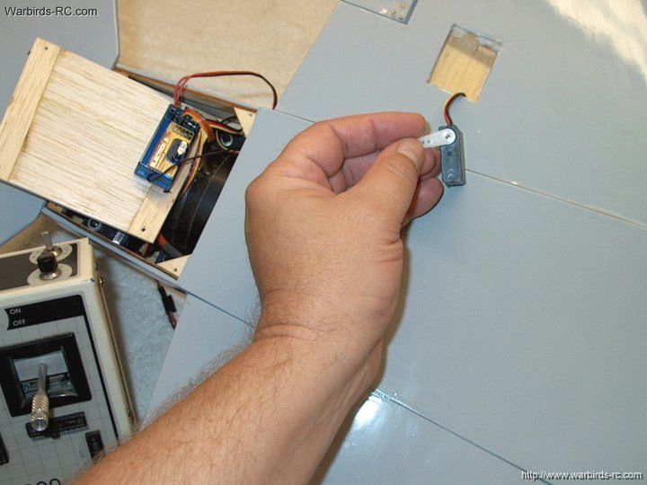
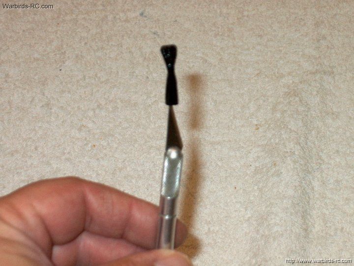
54 - Use a knife to hold the stake open
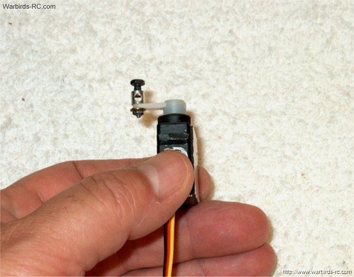
and apply epoxy to the inside of the stake
| |
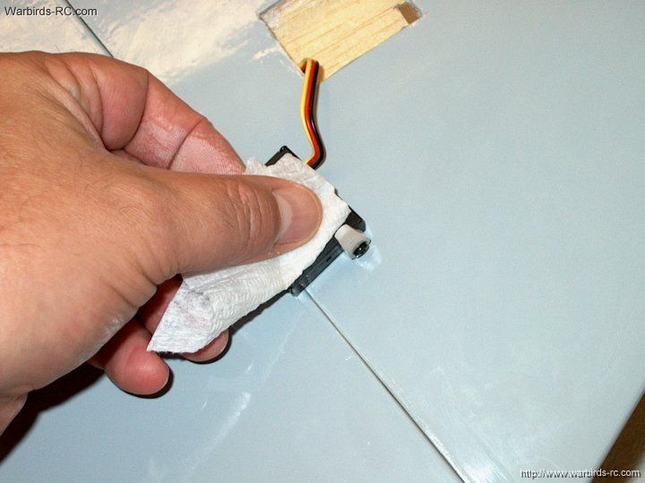
55 - Apply epoxy to the inside of the
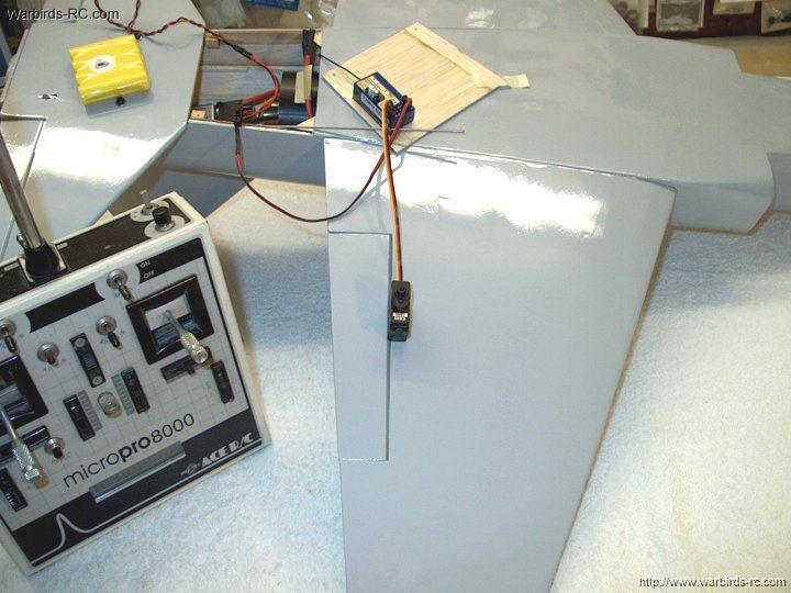
stake rather than on the Vertical Stab. This will keep the
upper seam clean and free of glue when the Stab is inserted
| |
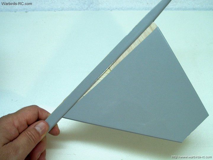
56 - Insert the vertical stab into the
stake and position it so it is flush to the bottom of the stake
| |
57 - Clamp the stake in place and use
alcohol to clean up the excess epoxy
| |
58 - Allow the epoxy to set and insure
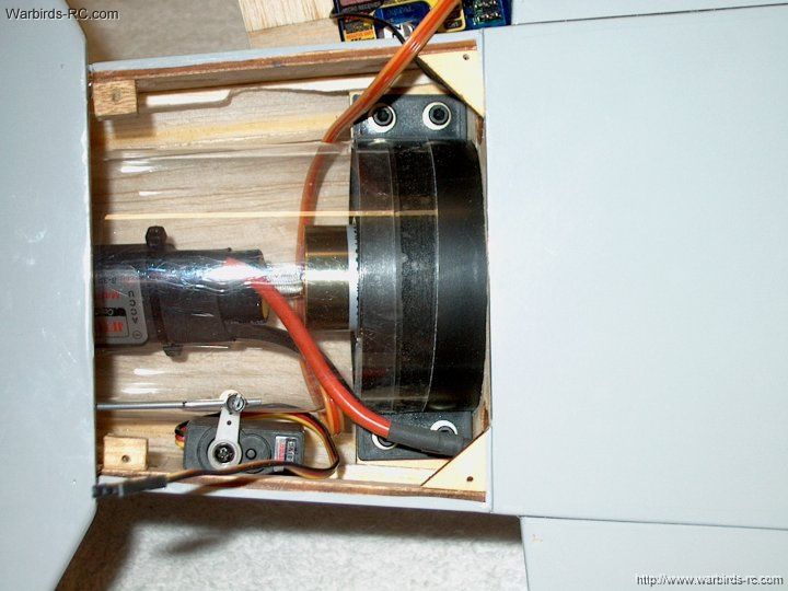
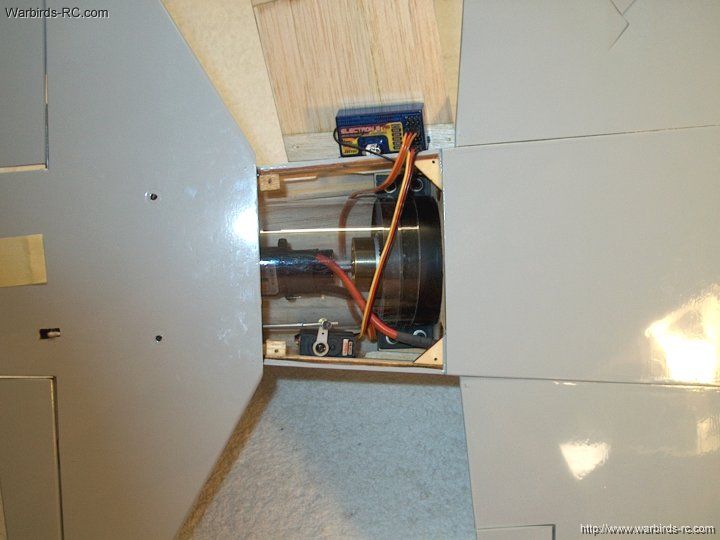
the front stake modification is at the front of the stab
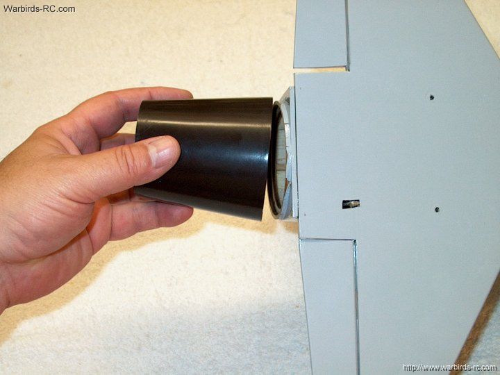
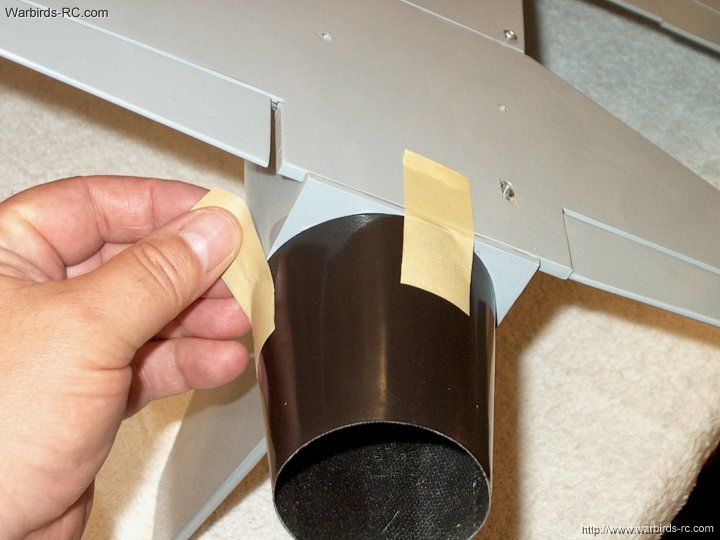
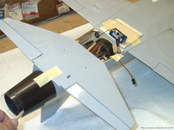
| |
59 - Make a mark at the underside of
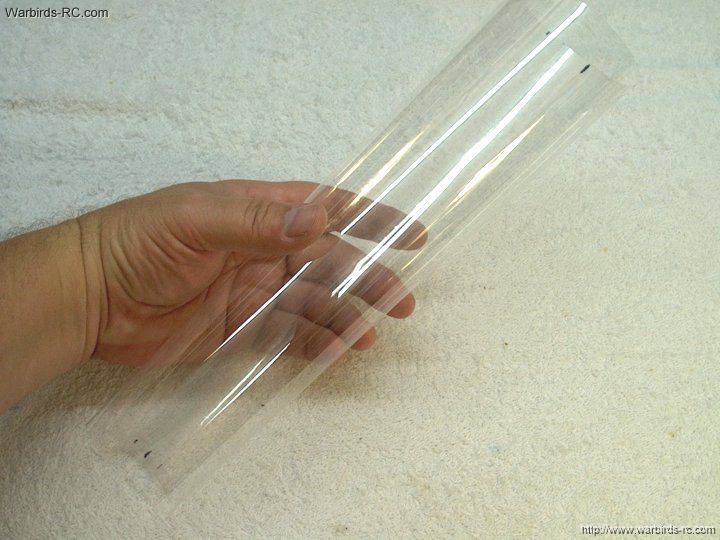
the center of the vertical stab
| |
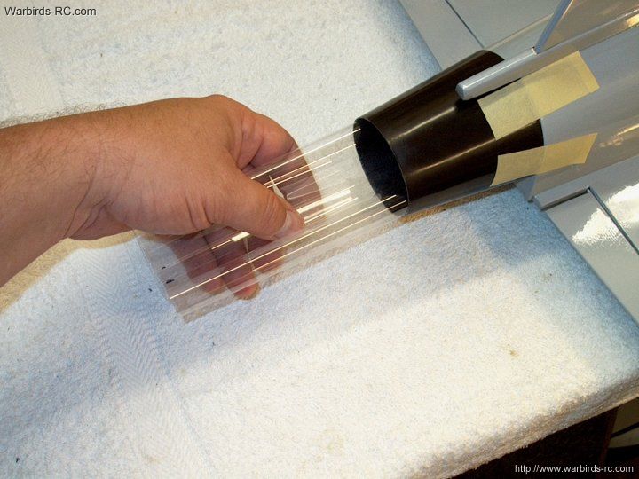
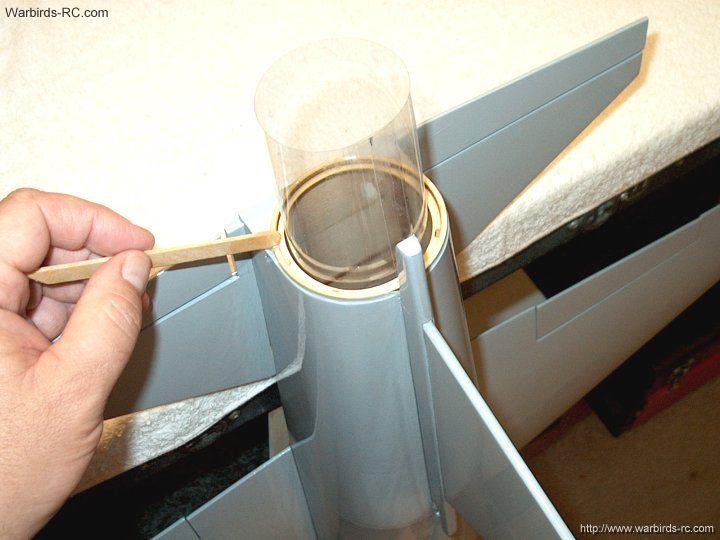
60 - Use pins to help keep the fin
aligned as shown and check the fit
| |
61 - Apply epoxy to the bottom of the
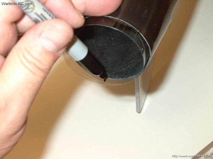
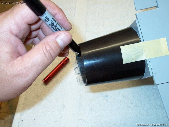
stab and on the fuselage
| |
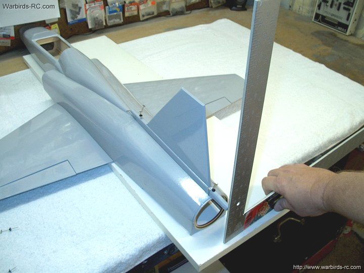
62 - Place the vertical stab assembly
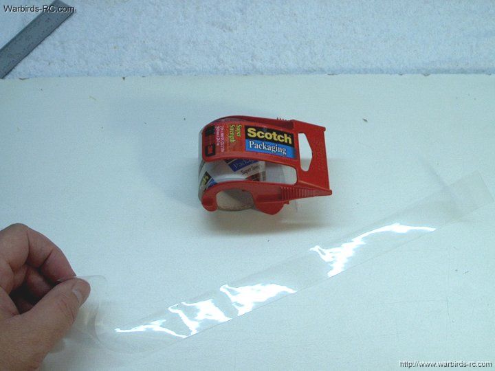
in position on the fuselage and pin it in place. Use a
square to align the stab perpendicular to the fuselage top
| |
63 - Use a pencil to locate and punch
through the pre-drilled holes in the horizontal stab
| |
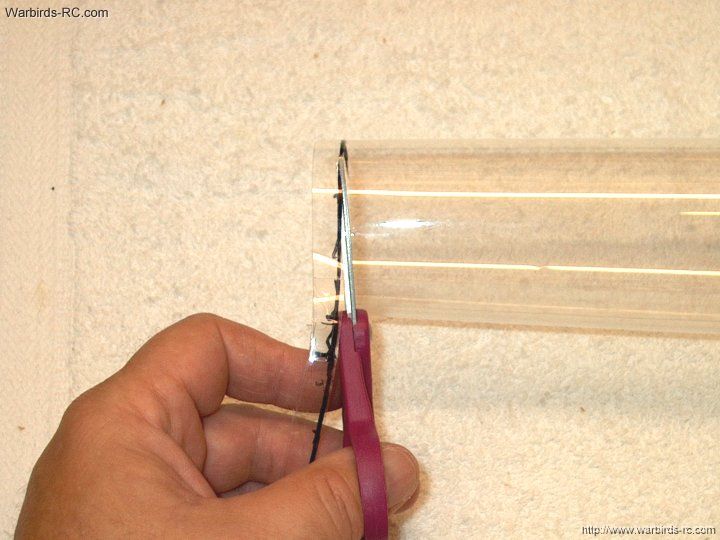
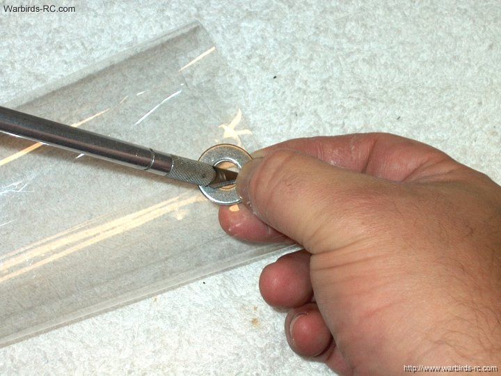
64 - Position the stab above its location
| |
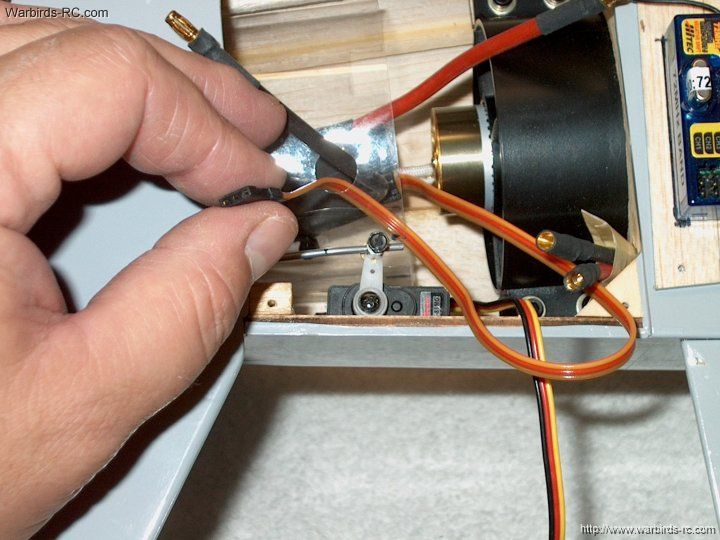
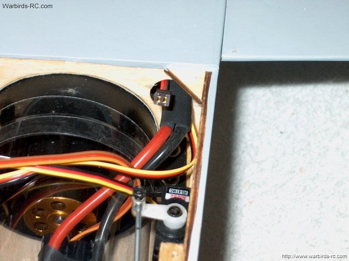
65 - Install the supplied bolts into
the stab holes
| |
66 - Temporarily install the horizontal stab
| |
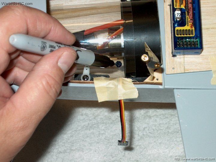
67 - Use a marker to mark the location
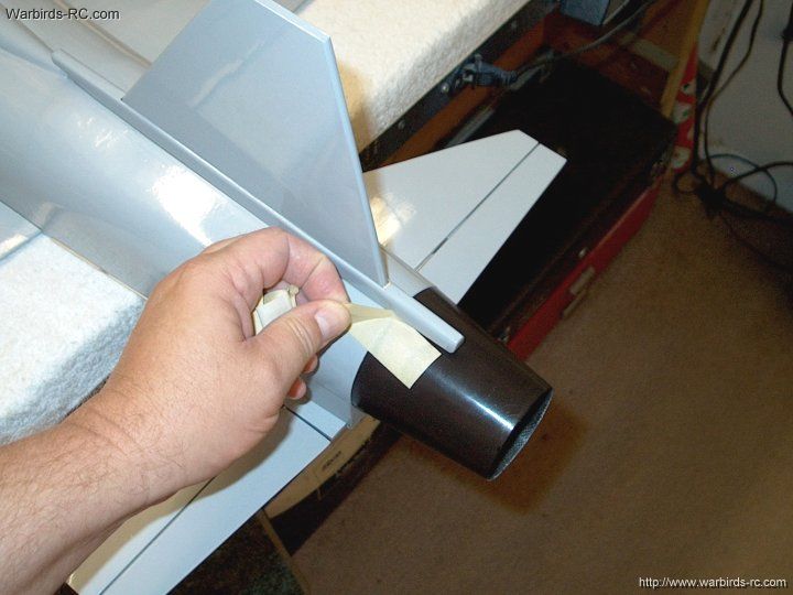
of the fuselage sides on the stab
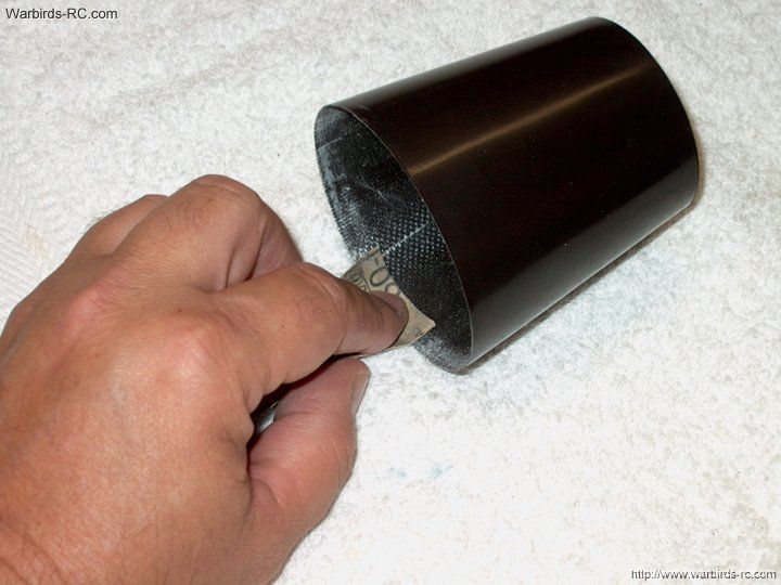
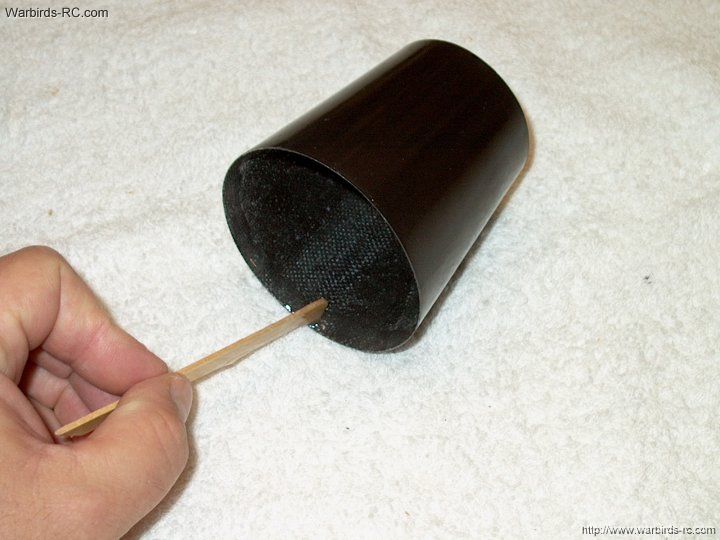
| |
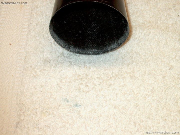
68 - Cut about 1/16" on the inside of
each line
| |
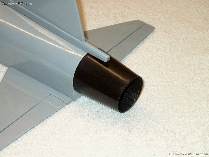
69 - Remove the center covering...SAVE
THIS COVERING! It can be reused to cover Aileron covers
later in the assembly
| |
70 - Remove the marker lines with alcohol
| |
71 - Seal the edges of the covering with an iron
| |
72 - The horizontal stab is ready to install
| |
73 - Trim the excess covering away
from the horizontal stab edges on the bottom of the fuselage
| |
74 - Remove the covering that was trimmed
fromt he top and front of the stab
| |
75 - Seal the edges of the covering
| |
76 - Apply epoxy to the bottom edges of
the fuselage
| |
77 - Apply epoxy to the trailing edge
of the horizontal stab
| |
78 - Install the stab on the fuselage
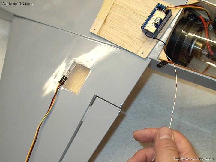
| |
79 - Use the stab bolts to hold it in
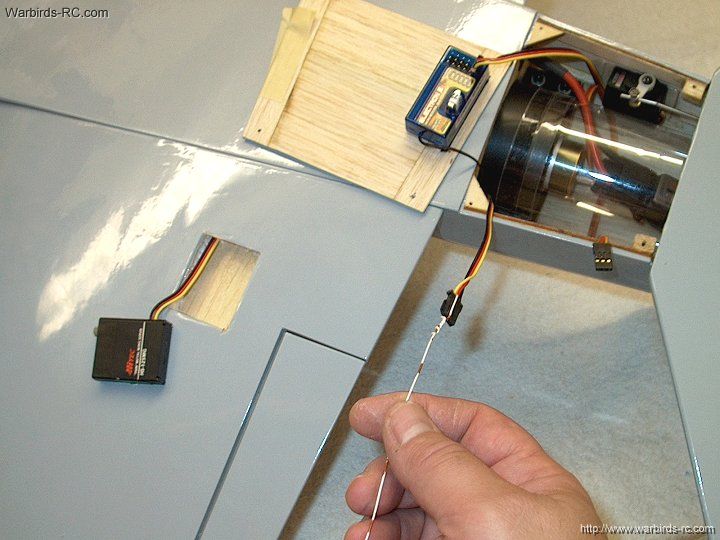
place while the epoxy sets. Check alignment of the stab
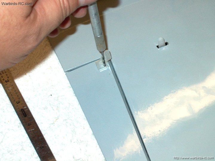
|
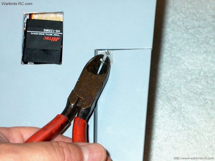
|
80 - Position the stab so it is flush
against the rear lip of the Fuselage, then use pins to hold
the Stab down to the Fuselage edges...this is important...make
sure the fit is flush with no gaps
|
|
81 - Remove excess epoxy from the bottom
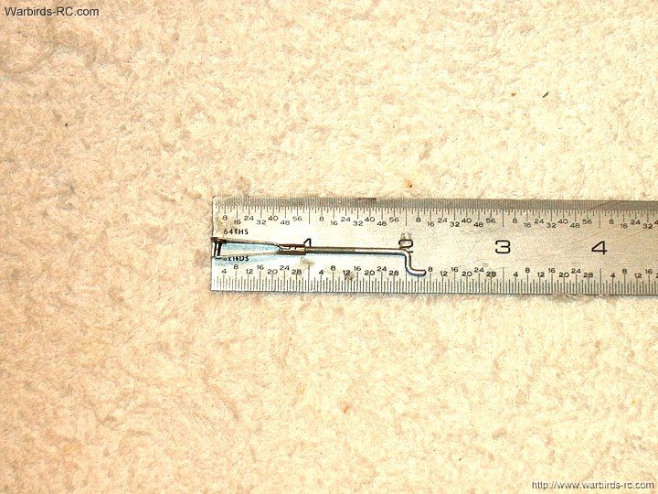
| |
82 - Remove epoxy from the fuselage joint
| |
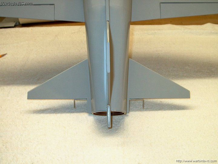
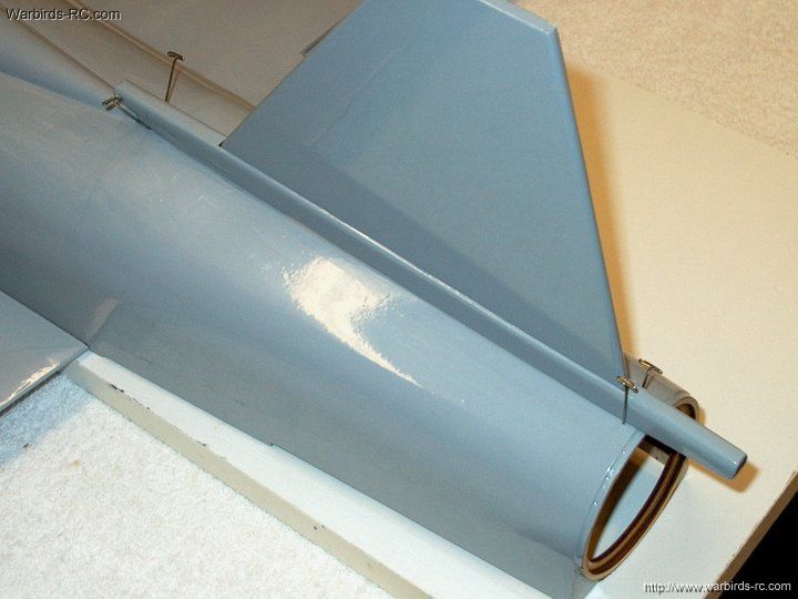
83 - Horizontal stab installation is completed
| |
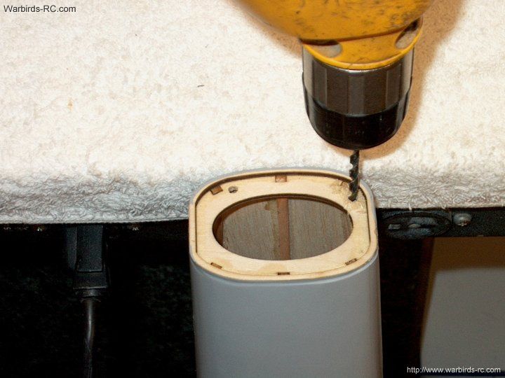
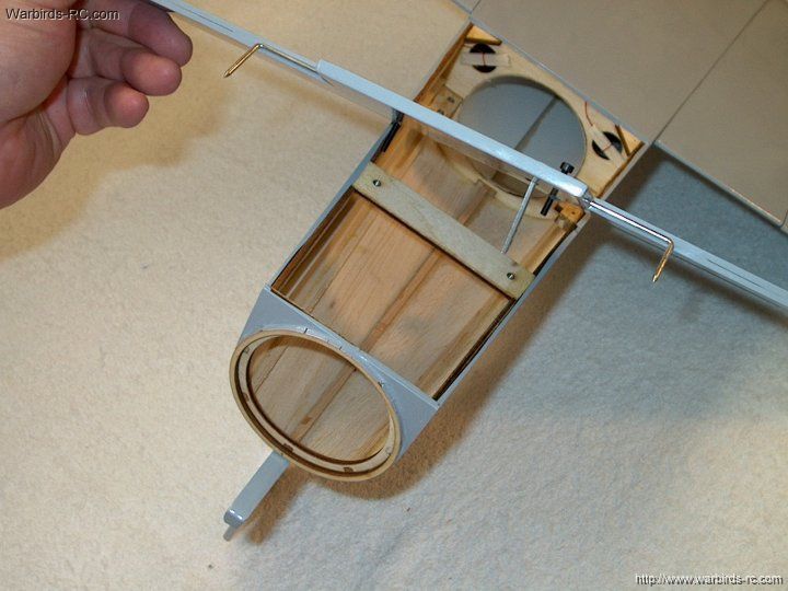
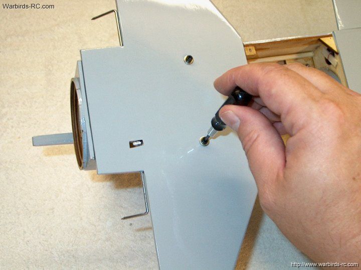
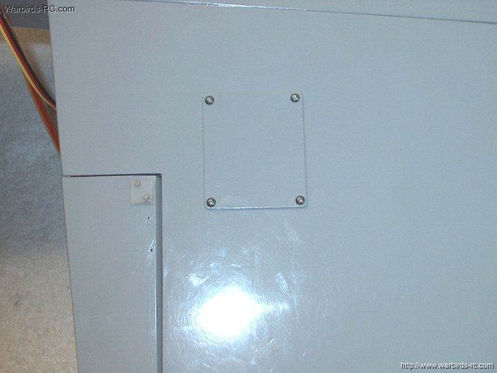
84 - Drill the fuselage front former for the
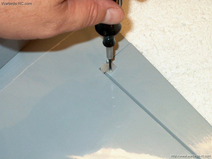
antenna tube
| |
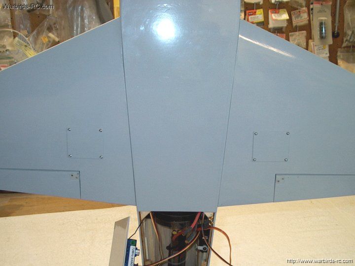
85 - Drill a hole in the rear firewall
former for the antenna tube.
| |
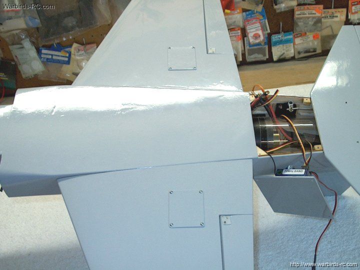
86 - The position of the antenna hole is shown
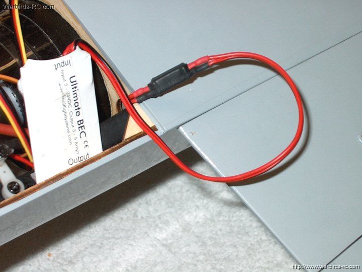
| |
87 - Drill a 1/8" hole in the rear of
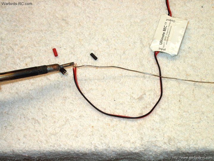
the fuselage for the antenna tube
| |
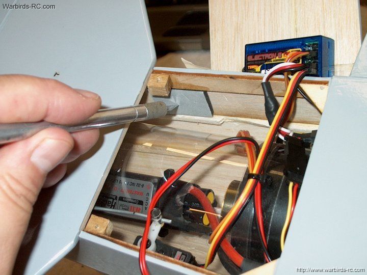
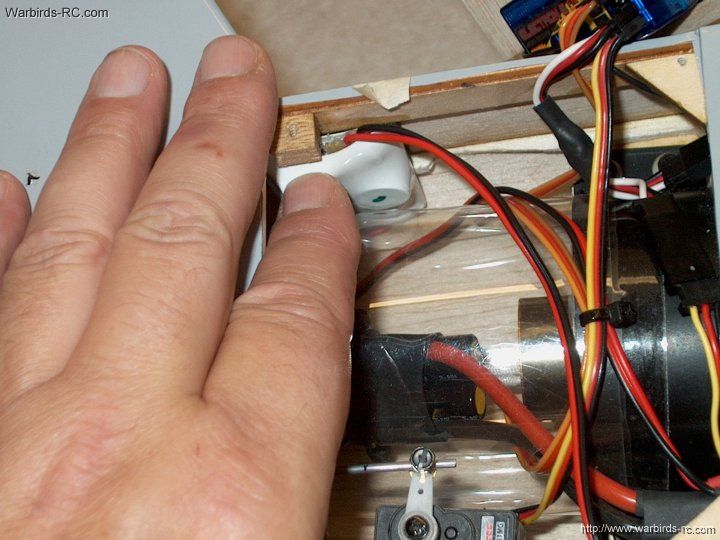
88 - Locate the red pull wires and
tape them out of the way to the bottom of the fuselage
| |
89 - Install the antenna wire tube
from the front
| |
90 - Ties the receiver antenna wire
to a string
| |
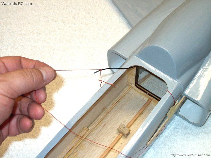
91 - Pull the antenna to the front
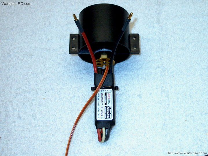
canopy area using the string | |
92 - slide the antenna tube rearward
over the wire. Mark the front of the tube for trimming | |
93 - Trim the antenna tube to length
| |
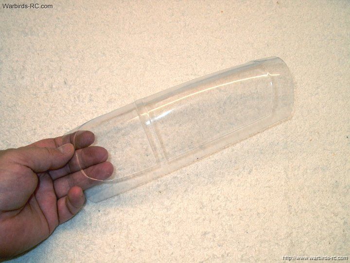
94 - Complete the antenna installation
| |
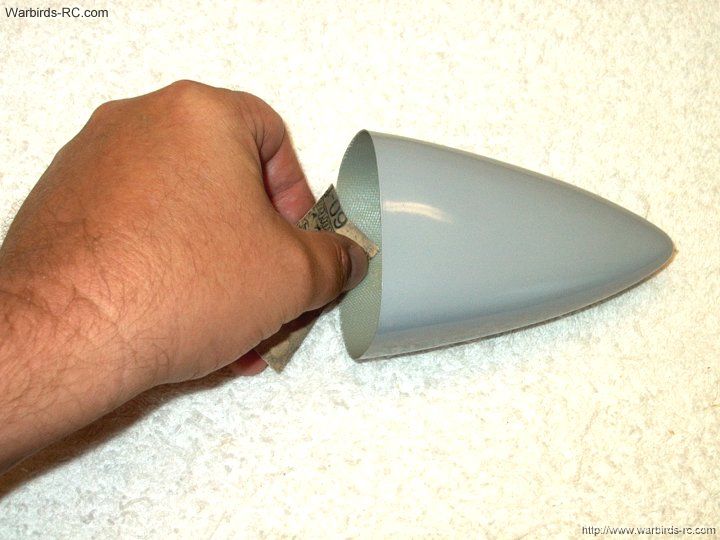
95 - Rough up the inside of the nose
with 60 grit sandpaper
| |
96 - The inside lip should be sanded
as shown
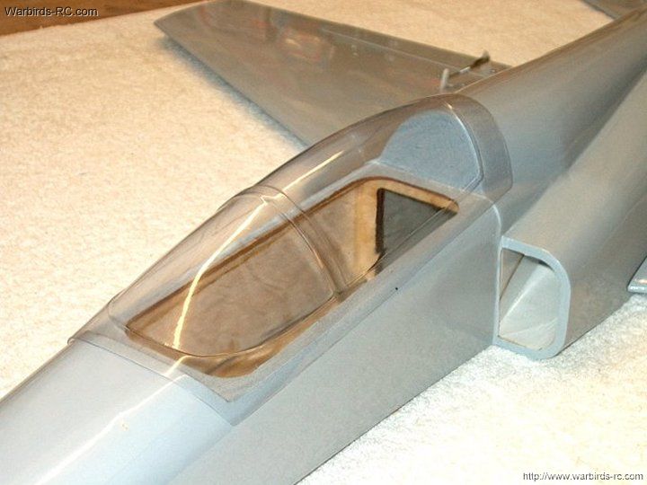
| |
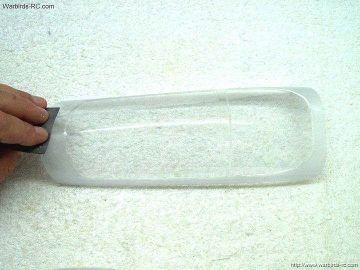
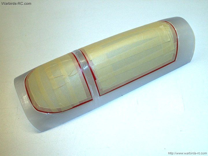
97 - Apply epoxy to the front edge
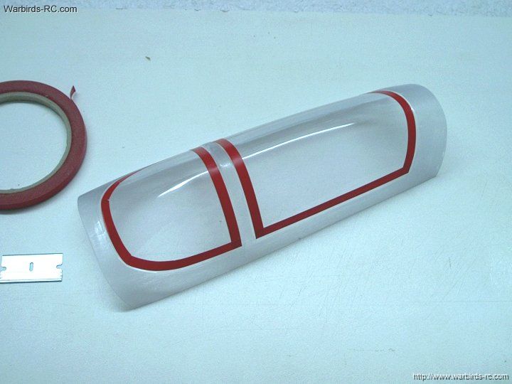
of the fuselage
| |
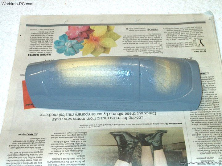
98 - Apply epoxy to the inside lip of
the nose
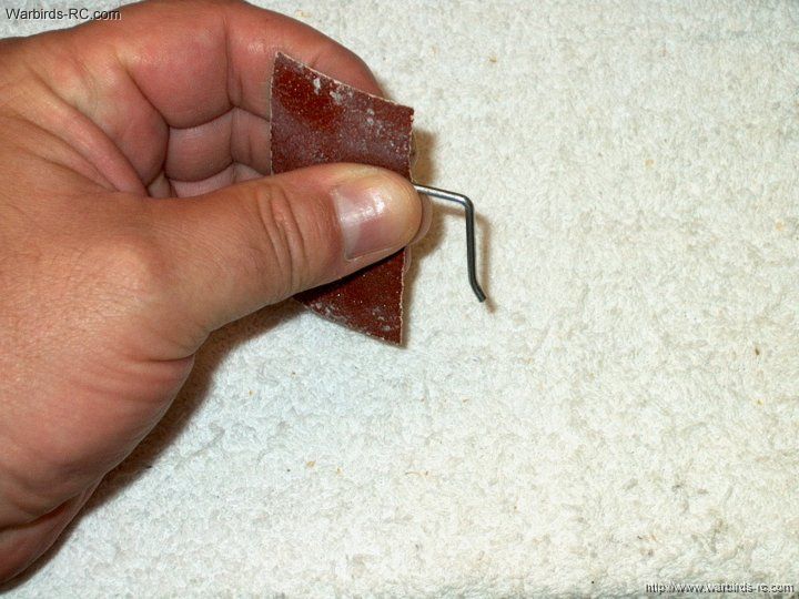
| |
99 - Install the nose on the front of
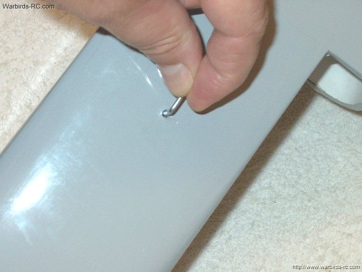
the fuselage
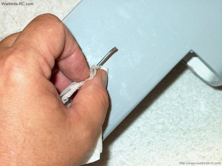
| |
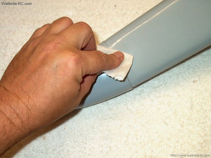
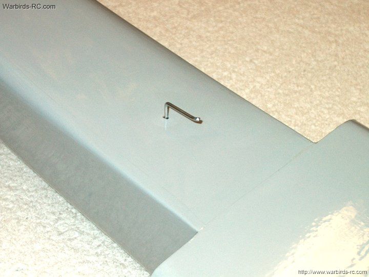
100 - Remove any excess epoxy with alcohol
| |
101 - Position the fuselage vertically
until the epoxy sets
| |
102 - The airframe build is completed
| |
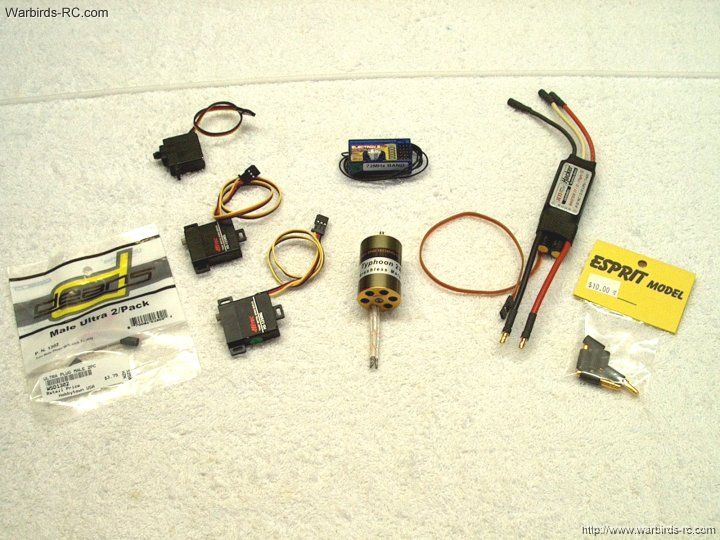
103 - Make sure you have all of the
parts you need to complete the electronics
| |
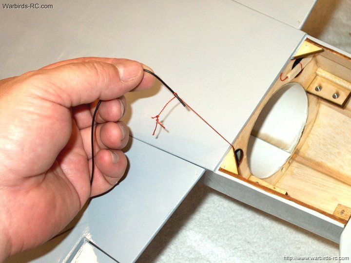
104 - Tie the black wire to the string
| |
105 - Pull the wire to the rear
| |
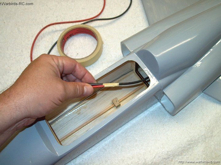
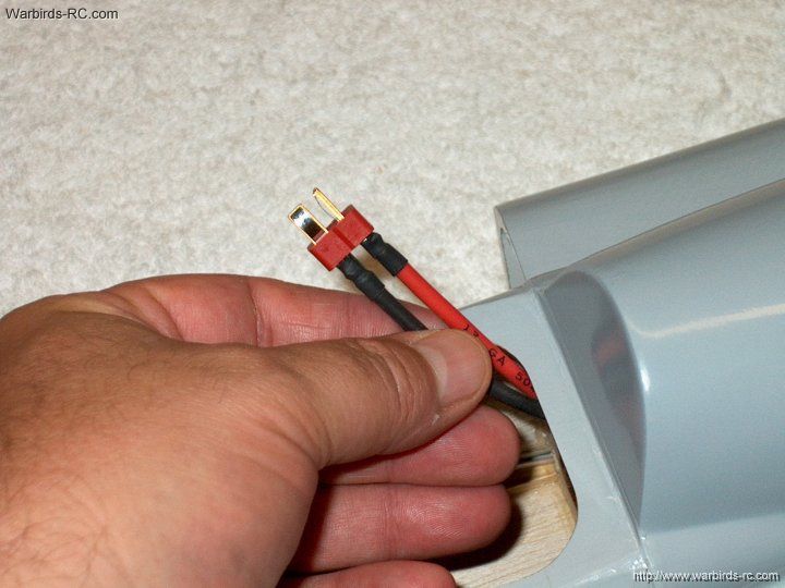
106 - TTape the red wire to the black
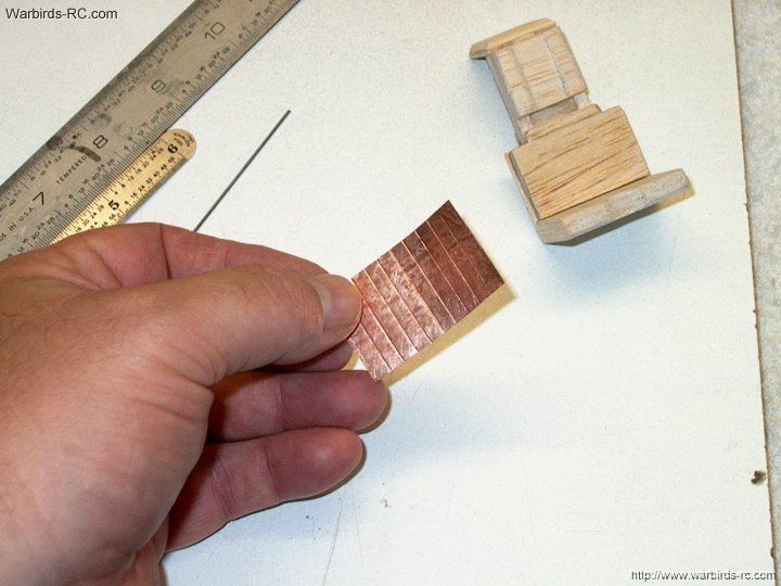
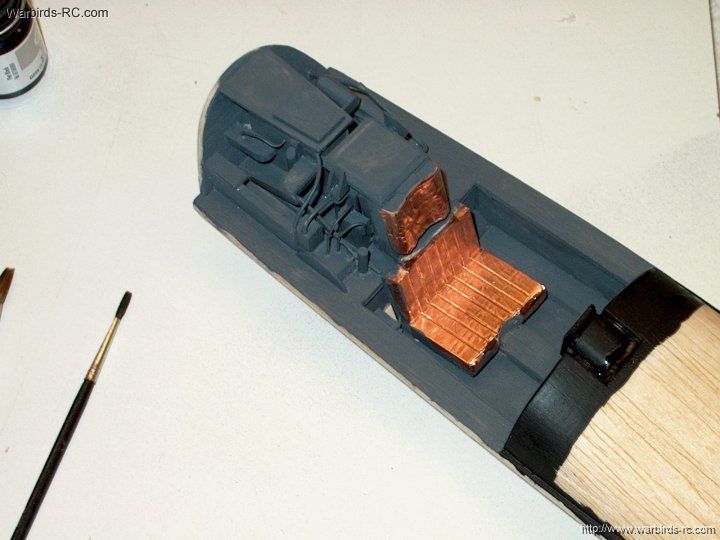
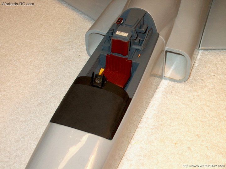
and pull them the rest of the way through to the rear
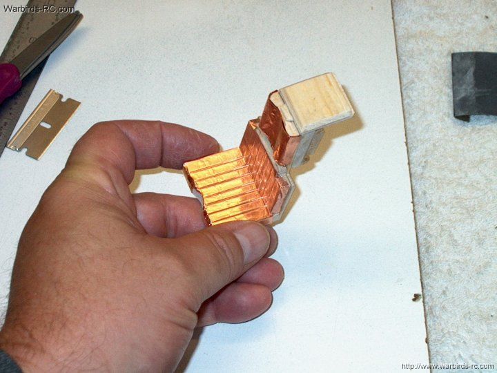
| |
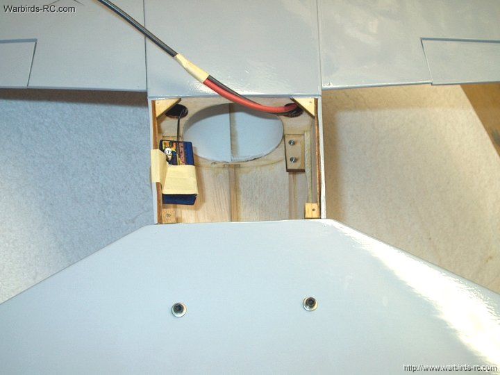
107 - The power wires should exit the
hole as shown
| |
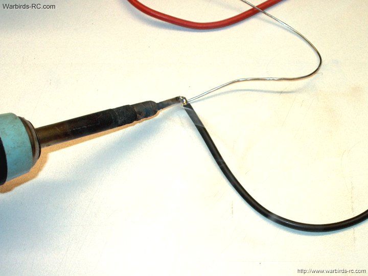
108 - Tin the end of both wires
| |
109 - Solder 3.5mm female barrel connectors
to each wire. Always install the sockets on the powered
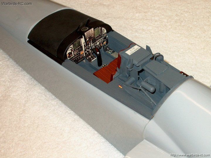
side so there are no plugs that can short together
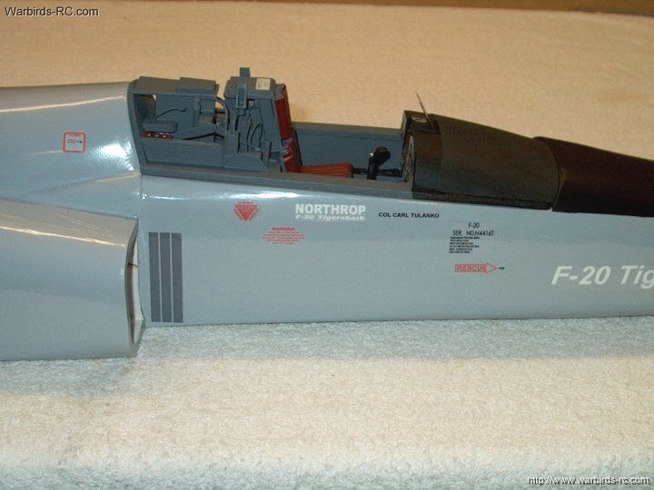
| |
110 - Use heat shrink to cover the sockets
| |
111 - Complete the installation for
both wires
| |
112 - Install 3.5mm female bullet connectors
on the powered side of the ESC and add heat shrink
| |
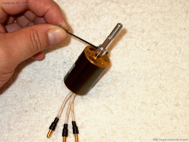
113 - Install male connectors to the motor leads
| |
114 - Apply heat shrink to cover the motor plugs
| |
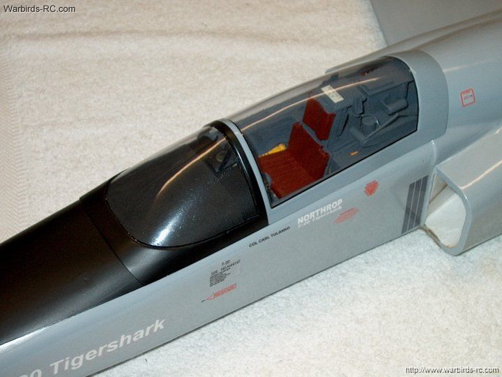
115 - The motor is shown completed
| |
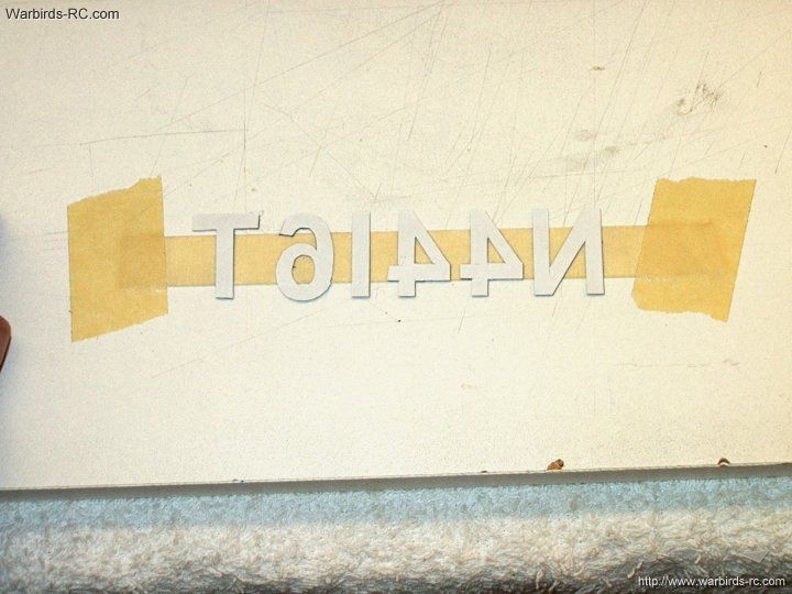
116 - Balance the fan rotor
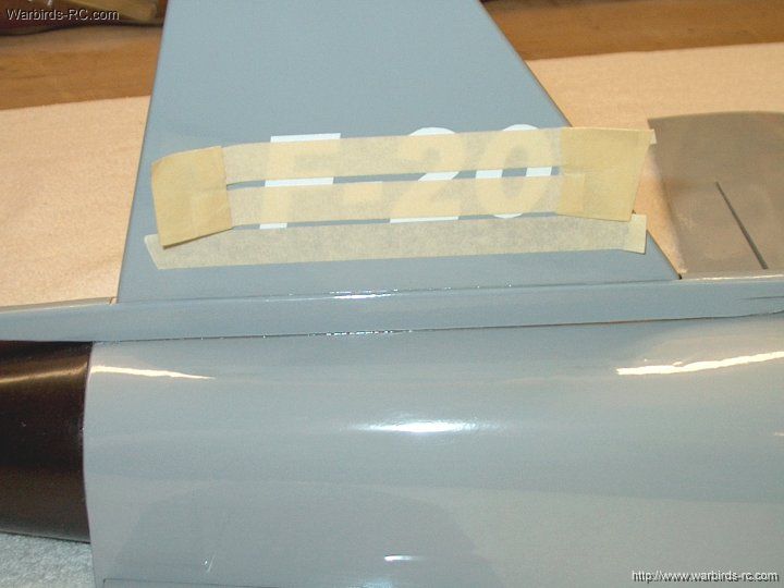
| |
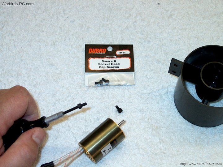
117 - Use 3mm x 6 bolts to mount the motor
| |
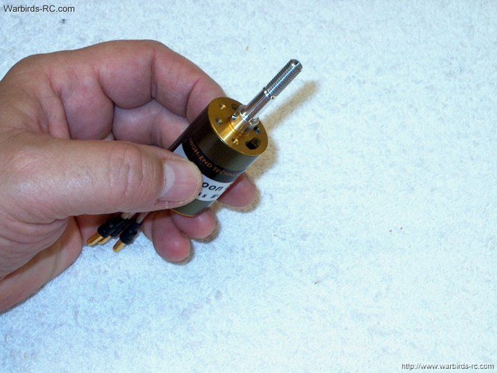
118 - Place the shaft adapter on the
motor shaft
| |
119 - Use the supplied set screw to apply
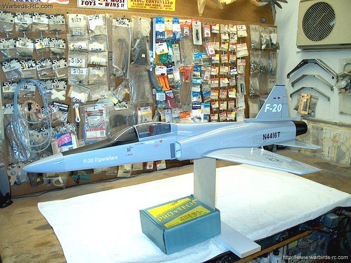
just enough drag to allow the adapter to be moved up and down
the shaft under some pressure
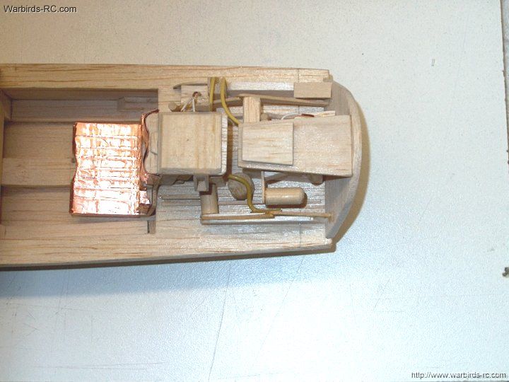
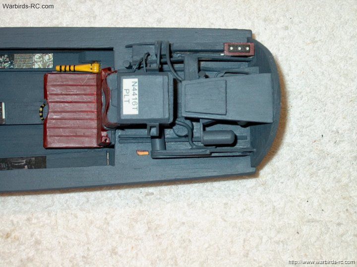
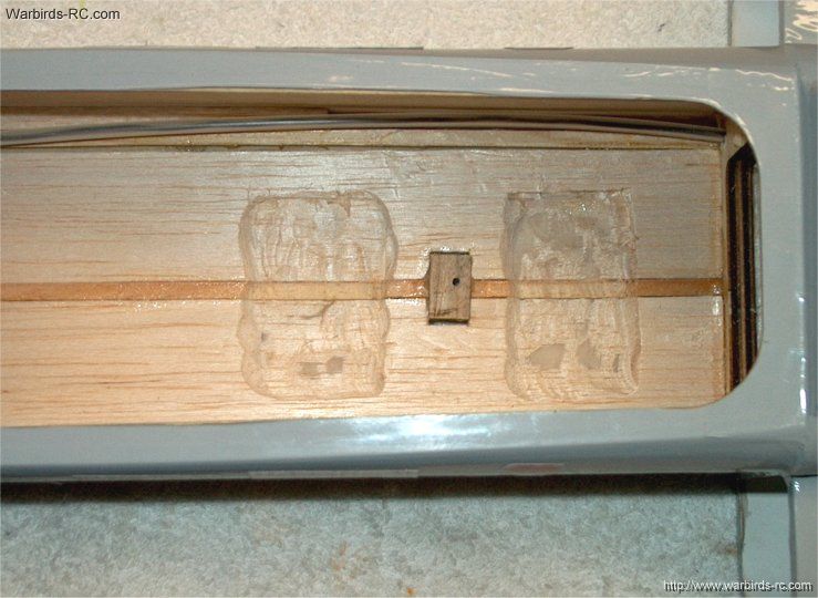
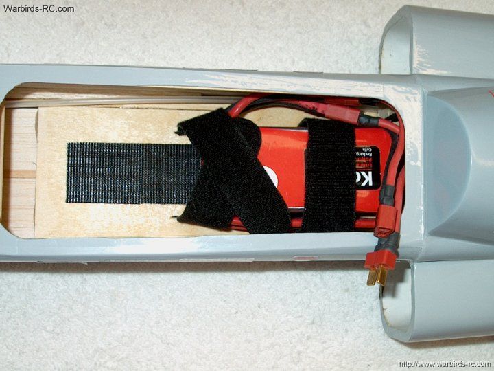
| |
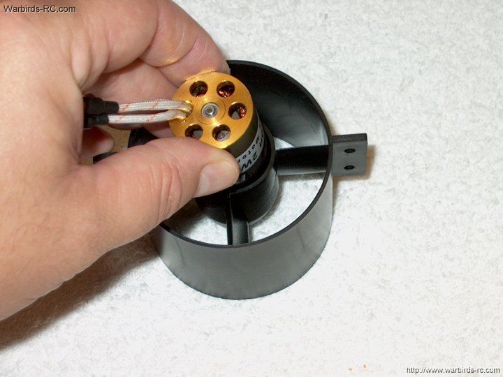
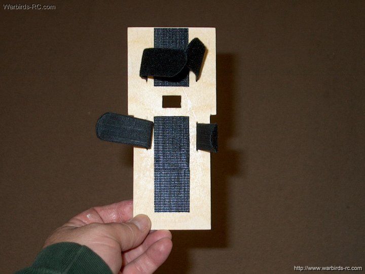
120 - Install the motor in the fan shroud
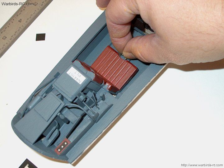
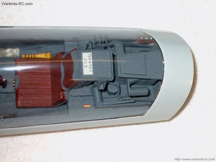
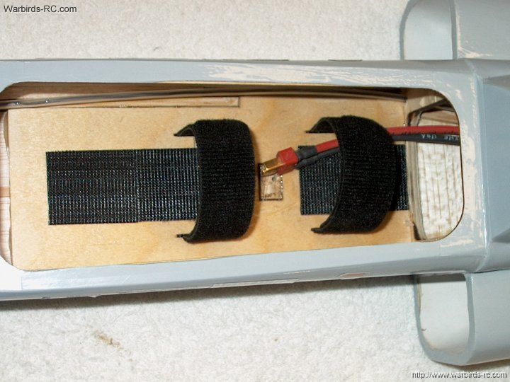
| |
121 - Temporarily install the 3mm bolts
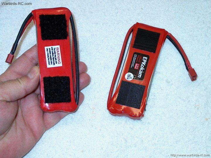
to hold the motor in place
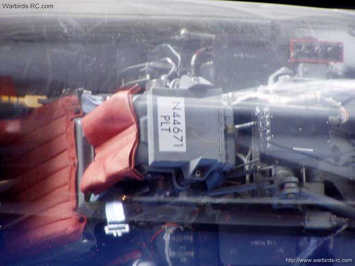
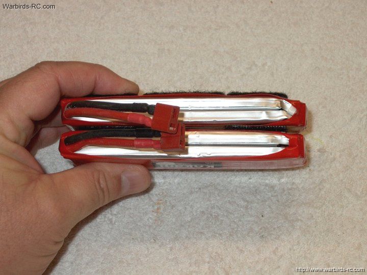
| |
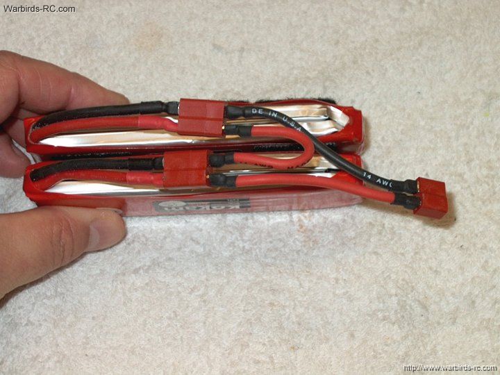
122 - Install the fan and push down until
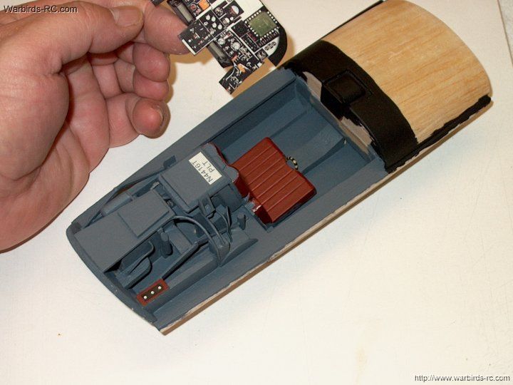
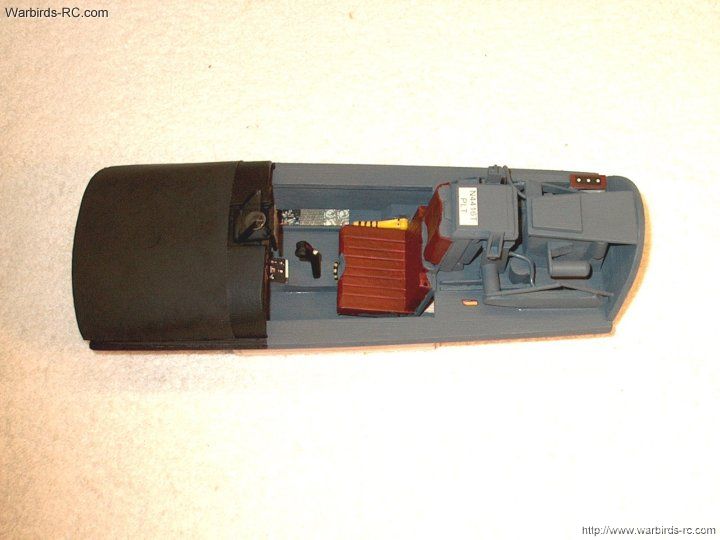
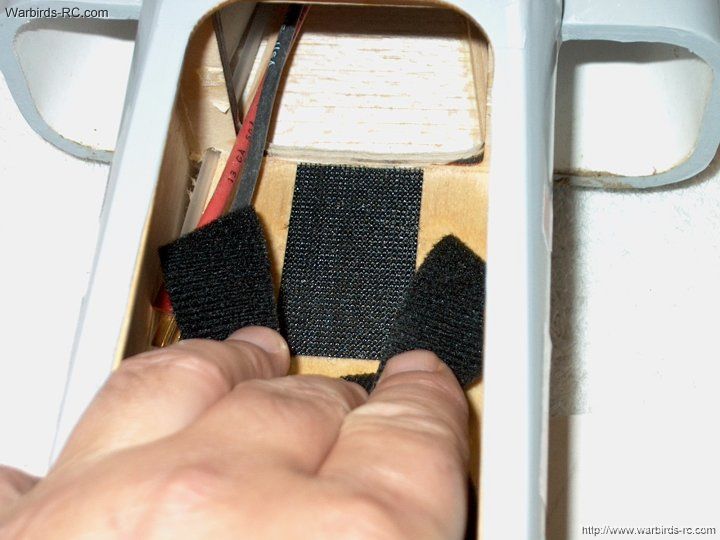
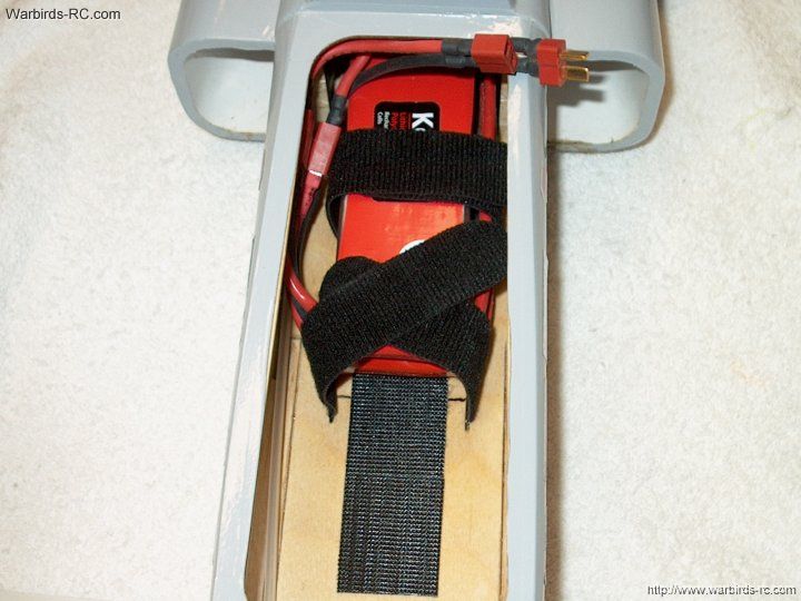
the fan bottoms out on the shroud area surrounding the motor
| |
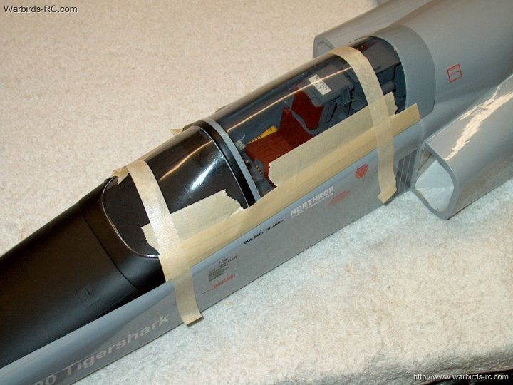
123 - Using your fingers, push against
the fan to keep it bottomed out on the Shaft Adapter. Pull
the Adapter out slightly to give about a 1/16" clearance
between the rear of the fan and the front of the motor housing
at the edges. This spacing will prevent the fan rear from
rubbing against the motor housing
| |
124 - Carefully remove the fan
| |
125 - Remove the motor from the fan
taking care not to disturb the shaft position
| |
126 - Apply Loctite to the set screws
and install them in the shaft adapter
| |
127 - Once the set screws are tightened,
use a Q-Tip to remove any excess Loctite
| |
128 - Apply Locktite to the motor threads
with a toothpick. Never apply Blue Locktite to the bolt threads,
or it can attack the plastic in the shroud. Another solution
is to use "Green" plastic safe Locktite
| |
129 - Install the motor in the fan shroud
| |
130 - Install and tighten the motor screws
| |
131 - Install the fan on the adapter shaft
| |
132 - Install the washer
| |
133 - Install the aluminum nut finger tight
| |
134 - Push the shaft through a piece of
paper, then a slot is cut dead center in the shaft with a
Dremel. The paper is used to keep any filings away from the motor
while cutting
| |
135 - The slot should be cut about 3/16"
deep in the threaded adapter
| |
136 - Use a flat bladed screwdriver
and wrench to tighten the fan nut
| |
137 - The fan assembly is completed
| |
138 - Slide a 2" long piece of heat shrink
over the three motor wires
| |
139 - Connect the ESC wires to the motor
| |
140 - Temporarily connect the receiver
and motor and test the fan direction. If it is spinning
the wrong direction, swap any two wires
| |
141 - Once you checked motor direction,
Finish heat shrinking over the connectors to hold them in place
| |
142 - Motor leads should look as shown
| |
143 - Tie wrap the ESC in place so
the assembly is semi-aerodynamic
| |
144 - A top view of the assembly is shown
| |
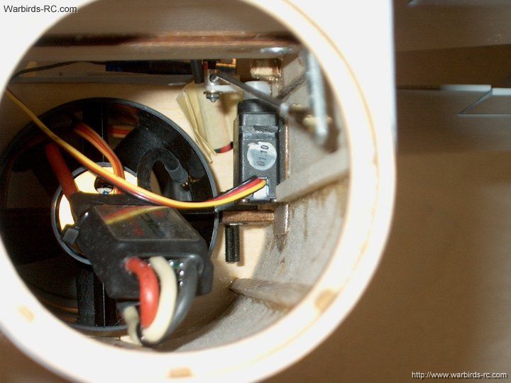
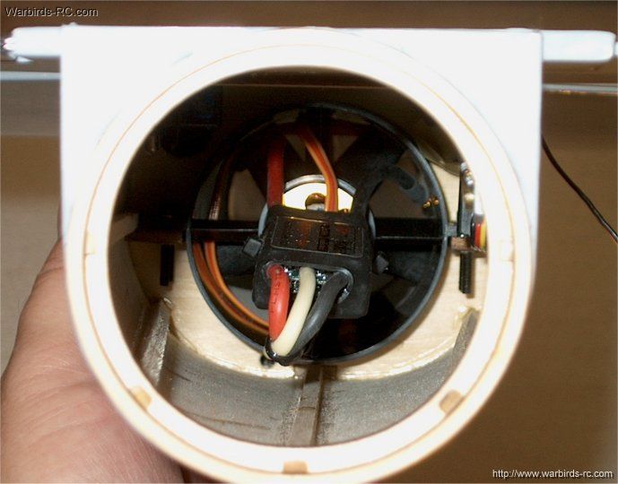
145 - Install the fan assembly in the fuselage
| |
146 - If you have difficulty sliding the
fan into the duct, slightly bell the mouth of the duct with
some fine sandpaper. Pic shows supplied mounting bolts being
installed. Note the inside where balsa was cut away on the
sides so the fan could be installed
|
|
147 - Apply double sided tape to the
bottom of the receiver
|
|
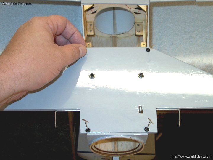
148 - Install the bottom cover plate
with screws, then used a ruler through the rear of the fuselage
to position the receiver and push it down in place. Note that
it has clearance so the Crystal and leads will not interfer
with the duct tube
|
|
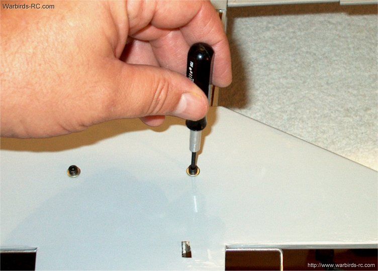
149 - Remove the bottom cover screws
|
|
150 - The cover shows receiver placement.
This is a good location as the receiver is not blocking access
to the Fan Assembly
| |
151 - Temporarily connect the HS81
servo to the receiver and turn on the radio to center the servo
| |
152 - Install the servo arm on the servo
| |
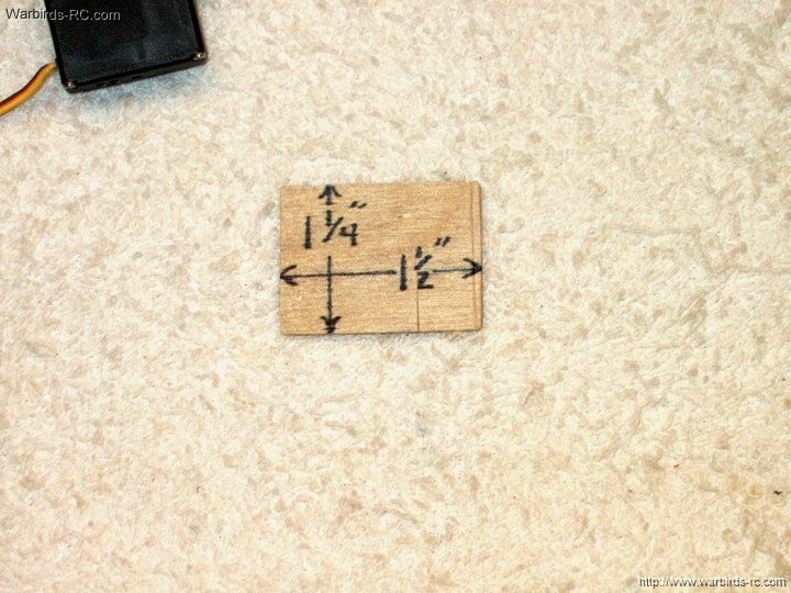
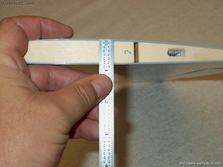
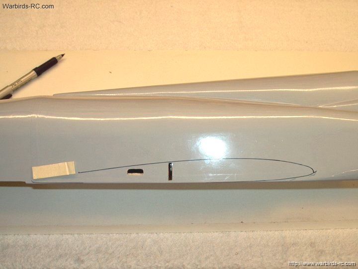
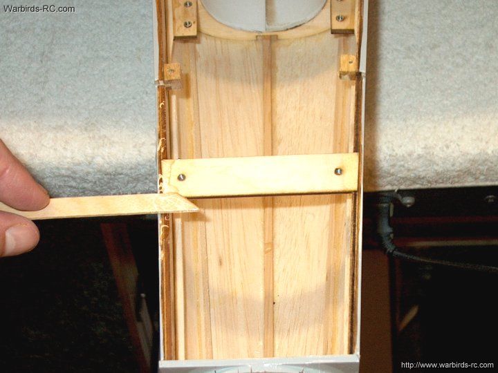
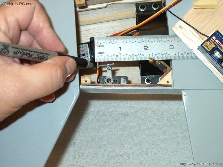
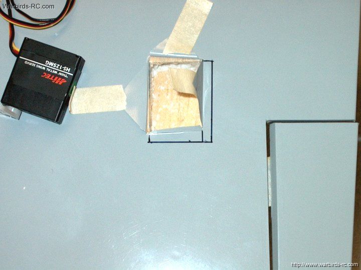
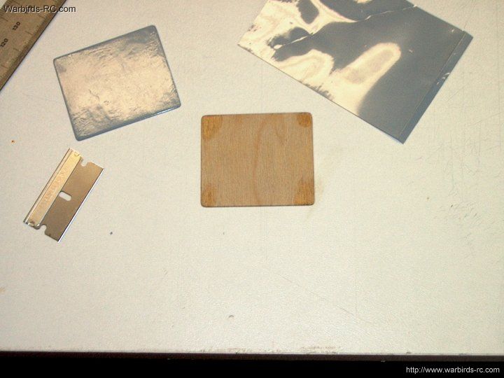
153 - Make a 1/32" thick plate with the
dimensions shown for mounting the elevator servo
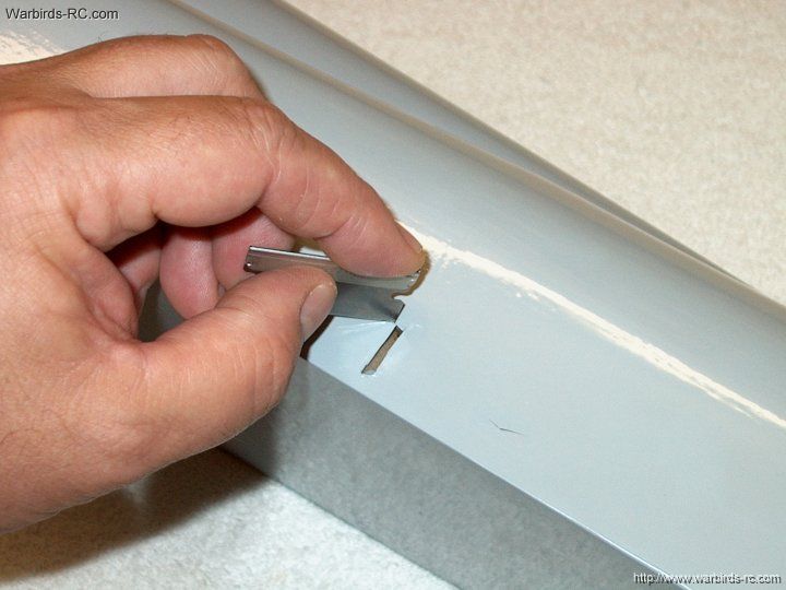
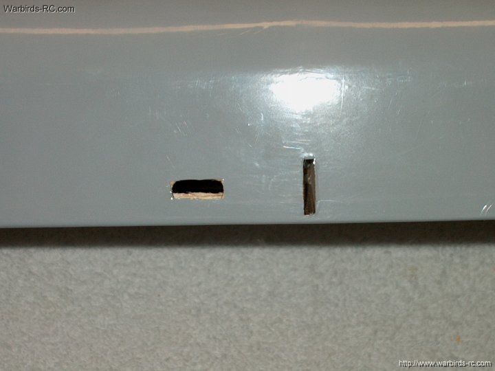
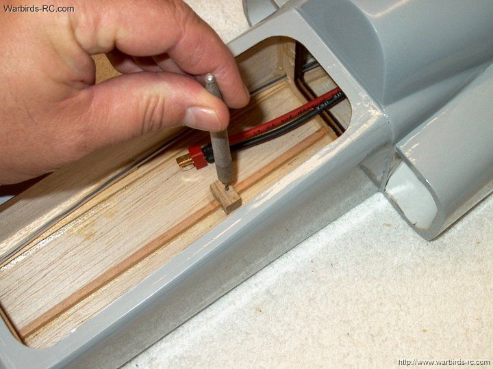
| |
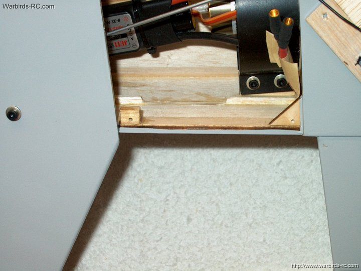
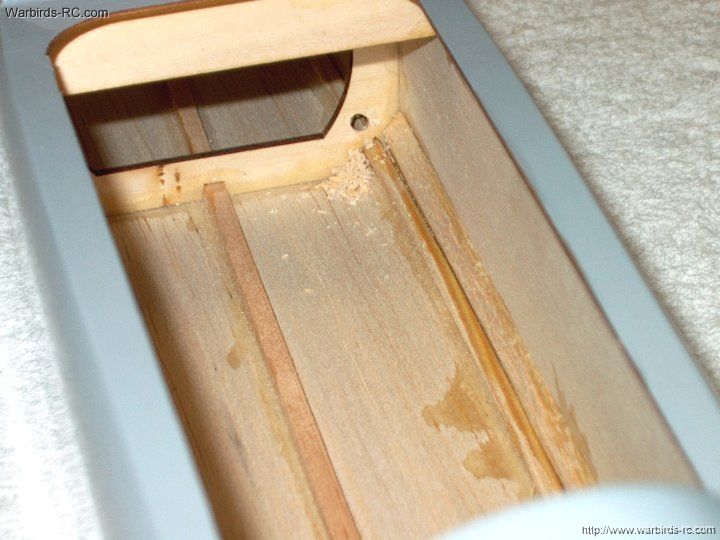
154 - Cut away the wood spar as shown
to make room for the elevator servo
| |
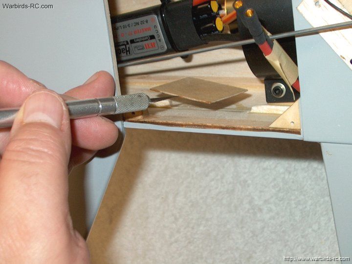
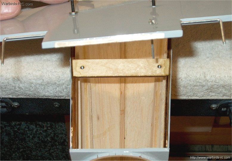
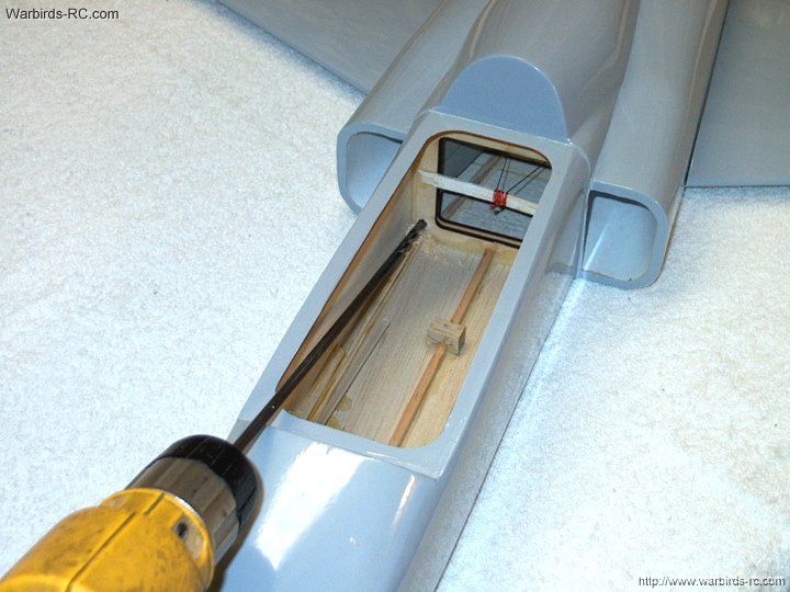
155 - Apply epoxy to the servo plate and
install it in place
| |
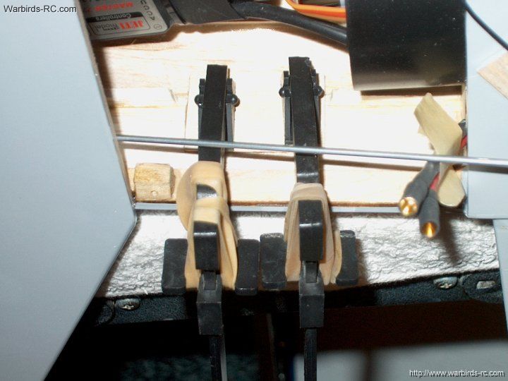
156 - Use clamps to hold the plate in
place while epoxy sets. Note the plate edge is about 1/4"
away from the ply supports near the fuselage opening
| |
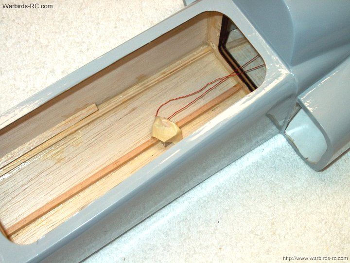
157 - The plywood plate is shown installed
| |
158 - Coat the plate with thin CA glue
| |
159 - Once the glue is dried, lightly sand
to a "plastic" feel for a good servo tape bond. Be sure to
clean the plate with denatured alcohol before mounting the servo
| |
160 - Clean the side of the servo with alcohol
| |
161 - Install double-sided servo tape
on the side of the elevator servo
| |
162 - Drill a 1/16" hole in the servo
arm to open it up for the pushrod
| |
163 - Install a Sullivan Pushrod
Connector #550 on the servo arm
| |
164 - Add a drop of CA on the bottom
threads so the nut will not come loose
| |
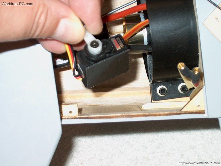
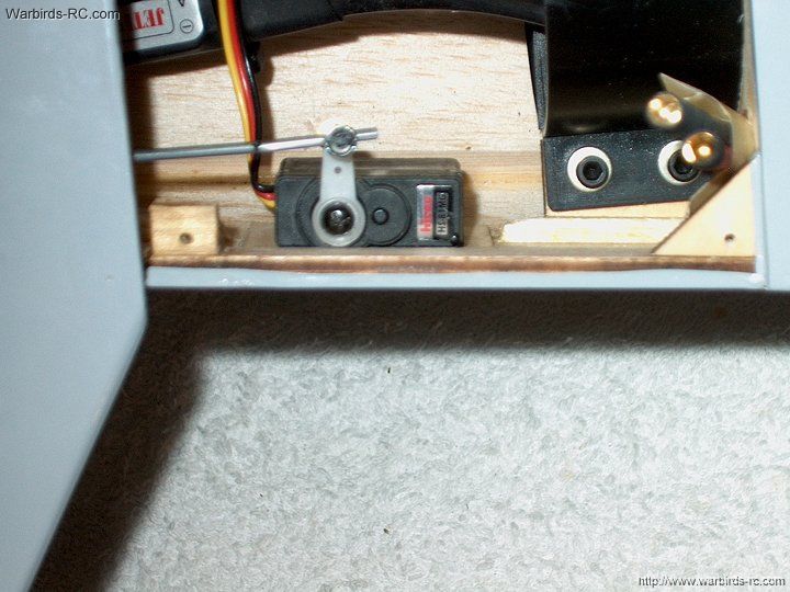
165 - Install the servo in the fuselage
| |
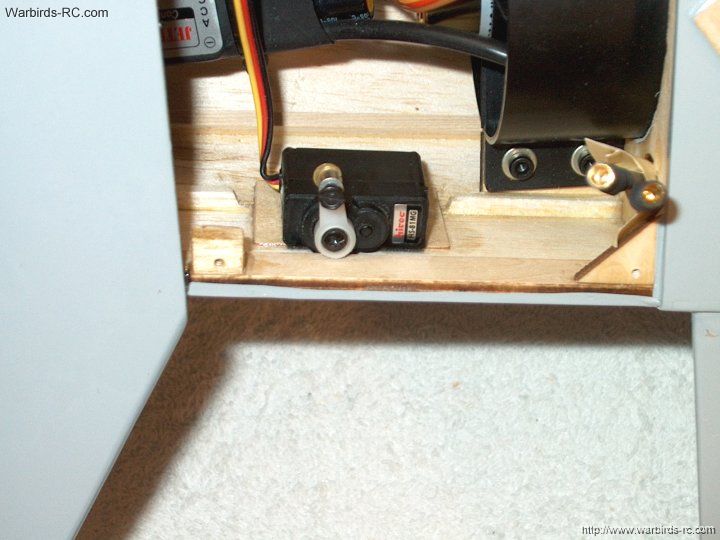
166 - The servo is shown installed
| |
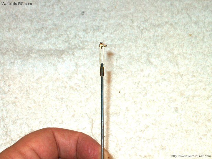
167 - Install a Sullivan Clevis on the
pushrod
| |
168 - Cut down the elevator horn one hole
as it is too long
| |
169 - Install the pushrod on the elevator horn
| |
170 - Mark the pushrod to length
| |
171 - Cut the pushrod at the mark
| |
172 - Make a mark on the pushrod
for bending, 1/2" from the servo arm center
| |
173 - Bend the pushrod to shape
| |
174 - Center the servo and elevators,
then install the pushrod and lock it in place with the screw
| |
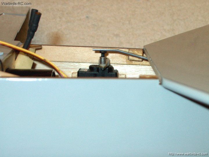
175 - The photo shows pushrod clearance
| |
176 - The fuselage rear assembly is
completed and ready for ducting
| |
177 - Temporarily mount the tailcone
| |
178 - Use masking tape to hold it in place
| |
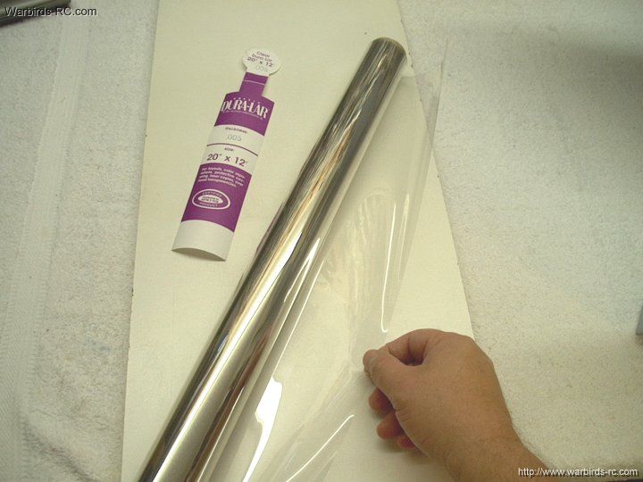
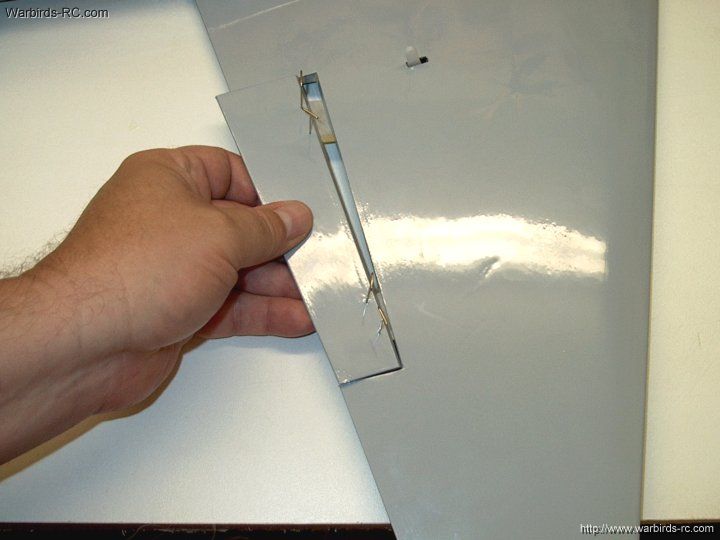
179 - Dura Lar is found at the craft
Hobby Lobby stores and a roll sells for about ten dollars.
I use the heavier .005 mil rolls and it makes excellent ducting
| |
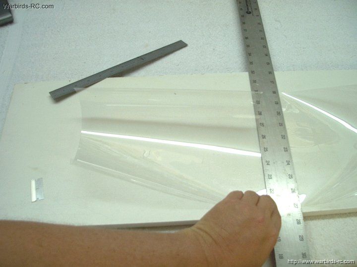
180 - Cut a duct sheet to 12" x 10"
| |
181 - Roll the sheet and install it
in the rear of the fuselage. Push it up against the fan
shroud and mark the shroud mount locations for cutting
| |
182 - Remove 3/8" squares from the sheet
| |
183 - Fit the duct and mark the other side
| |
184 - Cut the second mount out of the sheet
| |
185 - Re-insert the duct over the fan
shroud and make a center mark
| |
186 - The seam should be adjusted so
it is at the top of the fuselage and out of sight
| |
187 - Mark the rear of the duct at the end
| |
188 - Use heavy duty clear packing
tape to assemble the duct sheet
| |
189 - Tape the duct to shape
| |
190 - Fold the duct as shown and install
it in the fuselage | |
191 - A wood dowel can be used to ease
installation
| |
192 - Mark the tail end for cutting
| |
193 - Trim the tail to length
| |
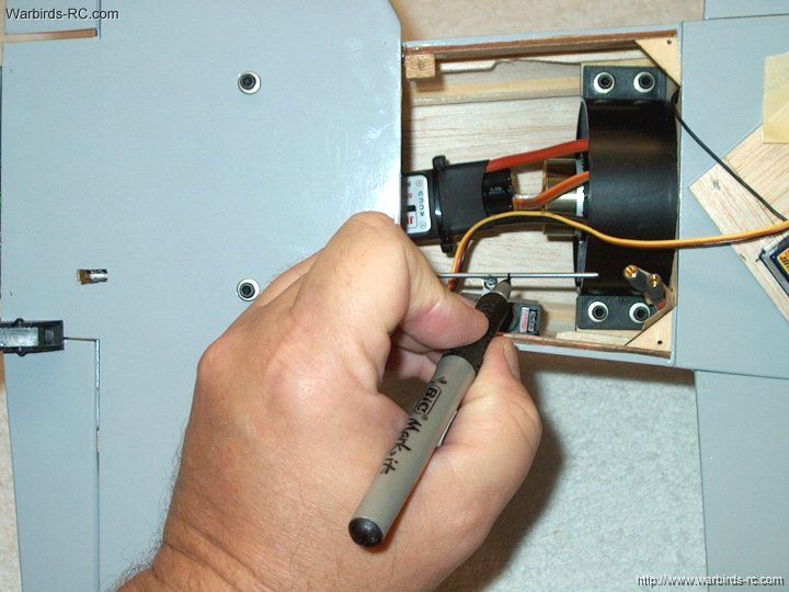
194 - Make a mark on the duct for the ESC wires
| |
195 - Sandwich the duct with a washer
on each side. Holding both washers tight, cut a perfect hole.
3/8" washers were used
| |
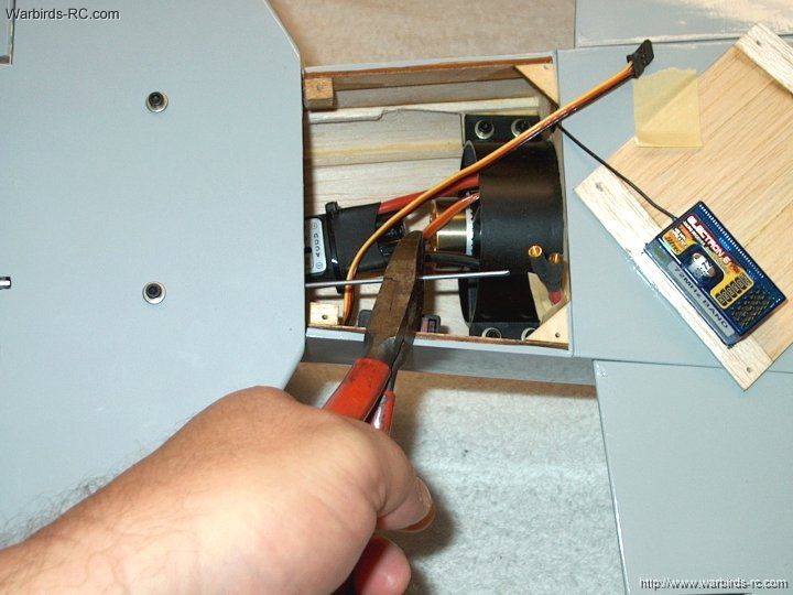
196 - Install the duct and feed the
ESC wires through the hole
| |
197 - Plug the ESC wires into the power harness
| |
198 - Cut a 3/4" wide of clear packing
tape and use it to hold the duct to the shroud
| |
199 - The duct should be taped as shown
| |
200 - Install the ESC receiver wire
| |
201 - The duct is shown installed
| |
202 - Remove the tail cone
| |
203 - Rough up the inside of the
tail cone with 60 grit sandpaper
| |
204 - The tailcone should be roughed
up about 1/2" deep in the tailcone
| |
205 - Add epoxy to rear of the fuselage.
As an alternative, you could use clear rtv silicon sealer
in four spots so tailcone could be removed later if ever needed
| |
206 - Apply epoxy to the inside of
the tail cone
| |
207 - Install the tailcone on the
rear of the fuselage and position the fuselage vertically
while the glue sets
| |
208 - Mark the center on each hinge
| |
209 - Draw centerlines down the hinges
| |
210 - Install a hinge 1/2" from the
inside end of each aileron
| |
211 - Use pins to hold the hinges in place
| |
212 - Install an aileron on the wing
| |
213 - Make sure both ends are evenly
spaced from the wing side area
| |
214 - Push the aileron down at least
15mm to allow it to space itdelf from the root
| |
215 - Use thin CA to glue the hinges.
Apply CA from both the top and bottom and immediately
clean up any drops of glue
| |
216 - Remove the pins and iron out the holes
| |
217 - Install the second aileron as the first
| |
218 - Use thin CA to glue in the second
aileron
| |
219 - Install and pin hinges in the elevator
| |
220 - Space a hinge 1/2" from the
control wire
| |
221 - Use pins to hold the hinges in place
| |
222 - Install the elevator
| |
223 - Make sure the tip of the elevator
is flush with the horizontal stab
| |
224 - Push the elevator down at least
15mm to allow it to space itdelf from the root. Glue
the hinge in place
| |
225 - Install hinges in the second elevator
| |
226 - Make sure the elevator is flush
at the end
| |
227 - Apply thin CA to glue the hinges
| |
228 - Cut open the Aileron servo
area in the wing. Open it up id necessary to fit your servo
| |
229 - Use an iron to seal the edges of
the servo bay
| |
230 - Sand the wing sheeting with 100
grit sandpaper
| |
231 - Use thin CA to coat and strengthen
the bay bottom
| |
232 - Use wire or string routed
to the receiver for the aileron wire
| |
233 - Tie the wire to the servo lead
| |
234 - Pull the servo lead to the rear
| |
235 - Cut a horn slot and temporarily
install the aileron. Install a horn to line up with the aileron
| |
236 - Trim off any excess bolt length
| |
237 - Route the second aileron wire
| |
238 - Sand the aileron bay smooth
| |
239 - Connect the aileron to the
receiver and center it
| |
240 - Clean the servo with alcohol
| |
241 - Apply double sided tape to the aileron
| |
242 - Install the servo in th bay
| |
243 - Install the second aileron horn
| |
244 - Make two aileron pushrods to
the dimensions as shown
| |
245 - Install a pushrod on the Aileron
| |
246 - Both pushrods are shown installed
| |
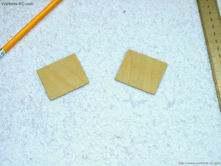
247 - Use some scrap 1/32" ply to make
the servo Aileron bay covers. They should be cut to 2"
x 1 3/4" in size
| |
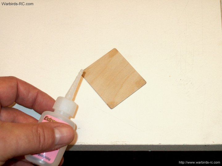
248 - Apply thin CA to both sides of
each cover ath the ends that will be drilled for mounting
| |
249 - Use the covering you saved from
the horizontal stab to cover the Aileron covers. Both panels
can be covered with the left over scrap
| |
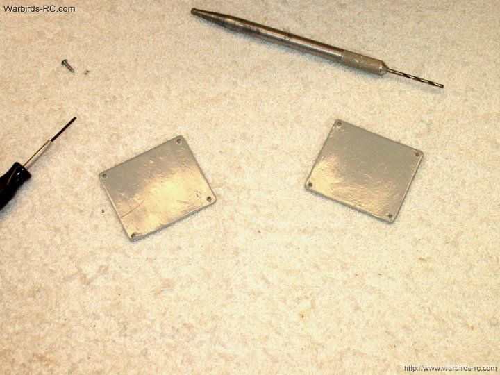
250 - The panels shown covered and
drilled with a 3/32" bit for #2 screws. Drill Matching holes
in the fuselage with a 1/6" drill bit using the panel as
a guide. Reinforce fuselage holes with a couple drops of CyA
| |
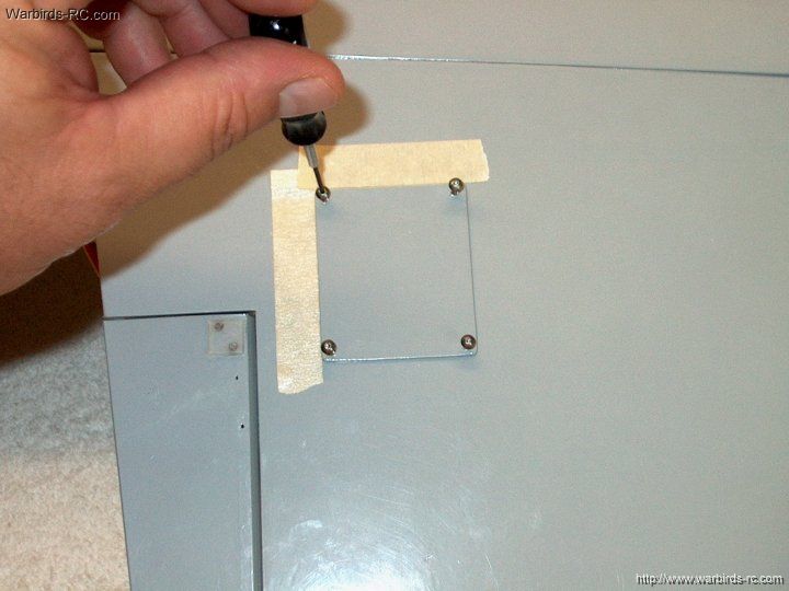
251 - Use button head screws to install
the panels
| |
252 - The second cover panel should be installed
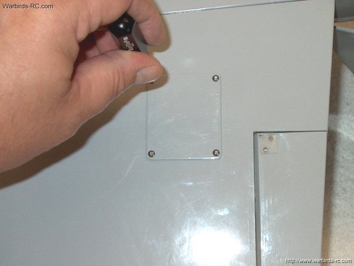
| |
253 - The panel should sit flush to the bottom
| |
254 - Panel installation is now completed
| |
255 - Side view of the panels
| |
256 - If you plan on using a U-BEC,
installa small set of power wires and micro Deans as shown
| |
257 - Heatshrink the connectors and
connect the main wires, then use heat shrink to cover them
| |
258 - A U-BEC was used, as
my ESC was an Opto version, requiring external power
for the receiver. Solder micro Deans on the U-BEC
| |
259 - Plug in the wire harness and
cover it with heatshrink so it doesn't pull apart
| |
260 - Install double sided, double thick
servo tape for the U-BEC
| |
261 - Install the U-BEC and plug it
in the receiver
| |
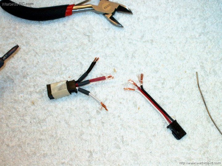
262 - A Y-Connector is required for the
Aileron servo's connection. You can either purchase a
connector or make one as shown
| |
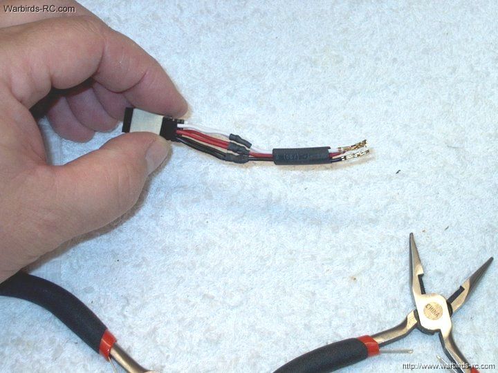
263 - Splice, solder and heat shrink the wires
| |
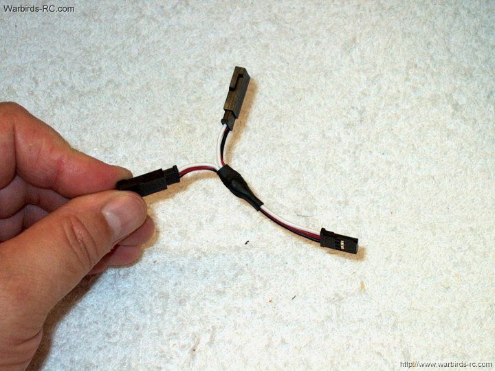
264 - Cover the center with heat shrink
| |
265 - Install all connectors in the receiver
| |
266 - Strip the power wires in the
battery area
| |
267 - Solder a Deans Ultra Connector
to the leads
| |
268 - Push on the heat shrink
| |
269 - Shrink the tubing to complete
the power wiring
| |
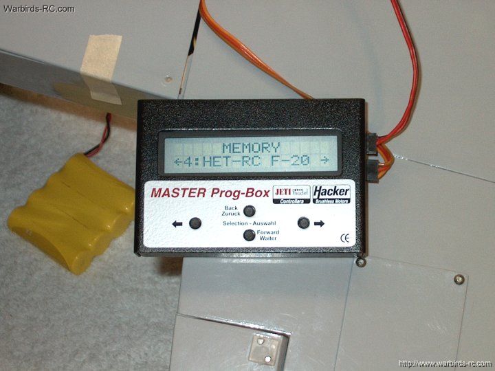
270 - I used a Hacker 77 Opto ESC
and programmed it for the HET 2W-20 motor and 4S Lipo
pack. Settings are as follows for the benefit of those
that use this ESC:
Type- AIRPLANE
Controller Type-
M-77-O
Brake- OFF
Timing- 18 DEGREES
Frequency- 16KHZ
Accelleration- MEDIUM
Accumulator Type- Li-Ion/LiPo1
Number of Cells- 4 LiIo/Po Lipo
Cutoff V Per Cell-
3.1
Cut Off- SLOW DOWN
Initial Point- AUTOMATIC
End
Point- AUTOMATIC
Throttle Curve- LINEAR
Rotation-
LEFT
Timing Monitor- ON
| |
271 - Set aileron throws to 12mm
| |
272 - Set elevator throw to 10mm Up
| |
273 - Set elevator throw to 5mm down
| |
274 - Set CG to 67-70mm behind the
root tip of the wing
| |
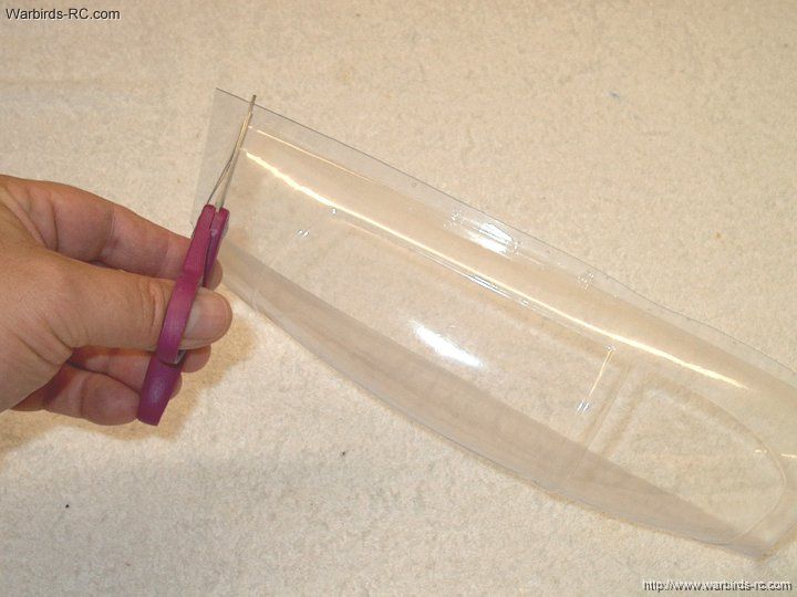
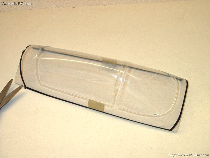
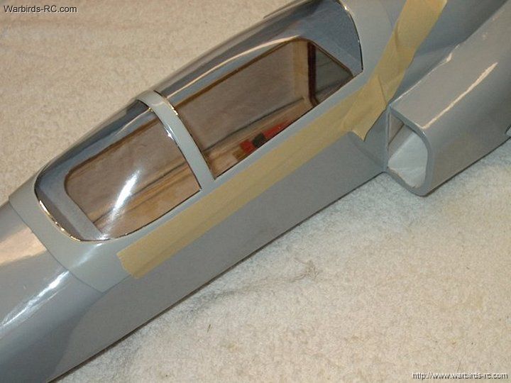
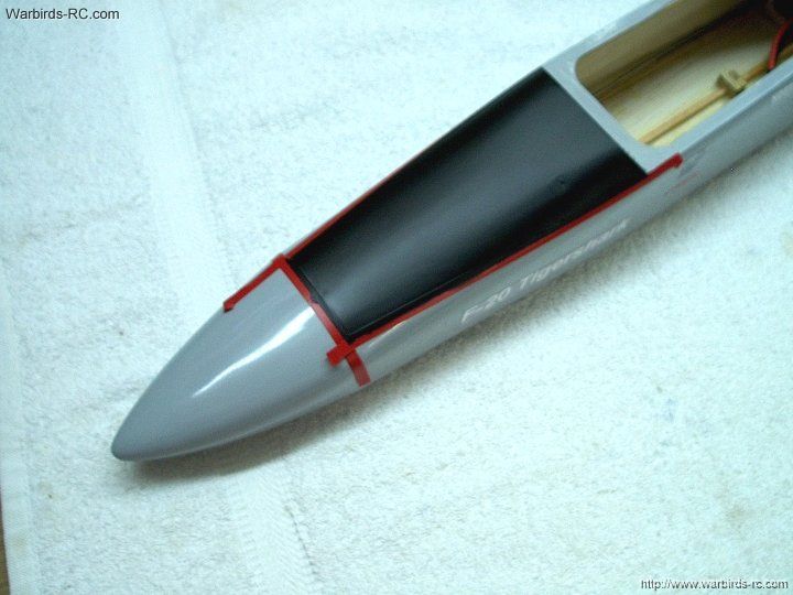
275 - Trim the ends of the canopy
| |
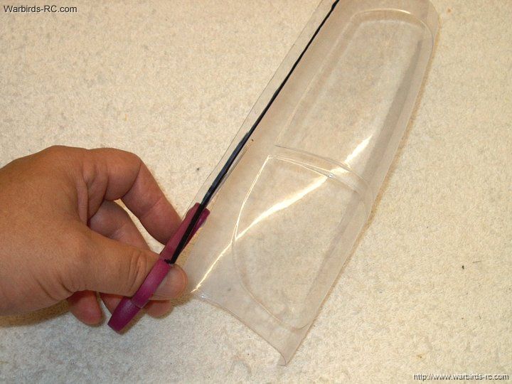
276 - Mark the bottom lip of the
canopy and trim it
| |
277 - Place the canopy on the center
of the fuselage, even on both sides
| |
278 - Use tape or a marker to evenly
lay a curve on the canopy front, and to mark the sides
and rear for final trimming
| |
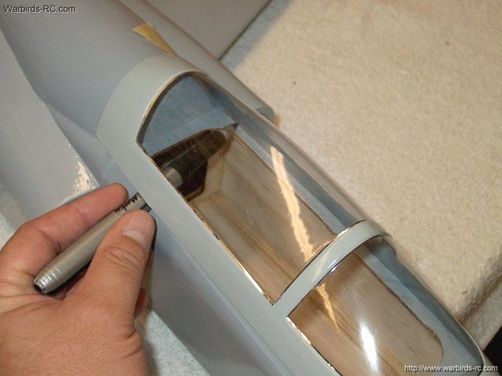
279 - Use trim tape to mark the final
shape of the fuselage
| |
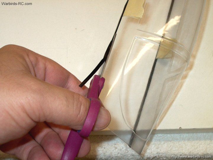
280 - Cut the canopy along the inside
of the tape or marker line
| |
281 - Canopy is ready for installation
| |
282 - Canopy is shown fitted to the fuselage
| |
283 - Lightly sand the areas to be
painted to a dull finish
| |
284 - Trim tape the inside window edges
| |
285 - Mask off the window area
| |
286 - Use a couple light coats of paint
| |
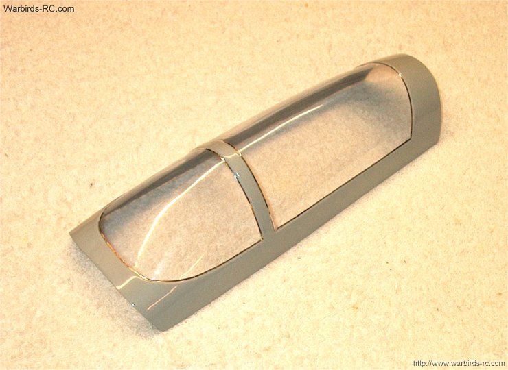
287 - Remove the tape from the canopy.
you can screw it on, use velcro or build a cockpit deck
| |
288 - Clean out the bungee hook hole
| |
289 - Rough up the first 1/2" of
the hook
| |
290 - Apply epoxy to the hook hole
with a toothpick and install the hook
| |
291 - Clean up excess epoxy with alcohol
| |
292 - Bungee hook installation is completed
| |
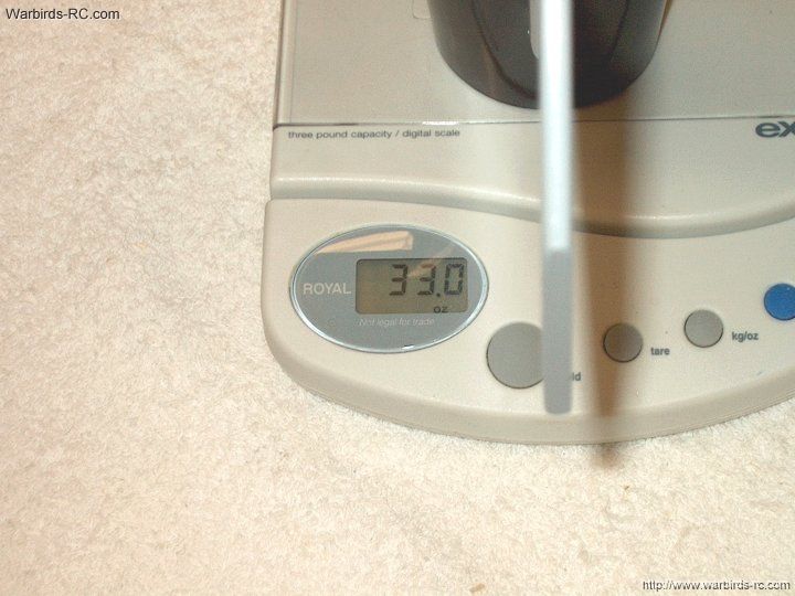
293 - Model with 4S electronics weighs
in around 33oz without batteries
| |
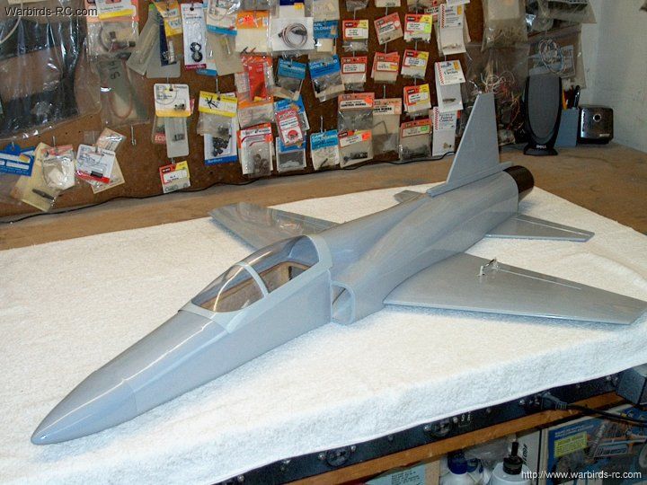
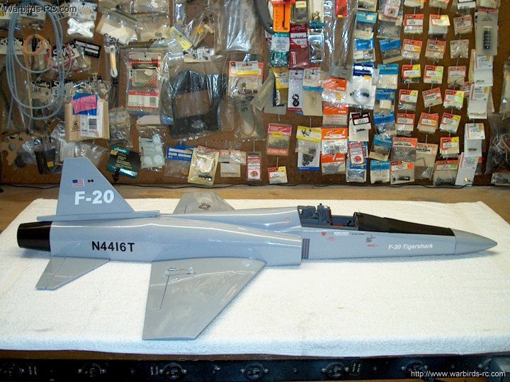
294 - The basic F-20 is shown completed
| |
295 - Hinge the canopy to the side
of the fuselage with masking tape
| |
296 - Use a marker on the inside of
the canopy to make a line showing where it sits flush
to the deck
| |
297 - Trim the canopy on both sides at
the line
| |
298 - Use a piece of 1/8" balsa for
the cockpit
| |
299 - Carve a piece of balsa for the
front deck
| |
300 - Add a 1/16" thick x 1/2" wide strip of
balsa sheeting to make an overhang for the instrument panel
| |
301 - Remove balsa for the HUD
| |
302 - Make the keypad plate and HUD
rails as shown
| |
303 - Cut a hole for the cockpit area
| |
304 - Use 3/32" balsa to frame up the area.
Be sure it is not too wide and clears the fuselage opening
| |
305 - Add a 1/16" thick balsa floor
| |
306 - Sand the floor flush on all sides
| |
307 - I have a roll of thin, stick
back copper sheeting, 2" wide. Use a similar material
to make a seat cushion . A small thin steel rule can
be used to make cushion marks
| |
308 - Apply the cushion to the seat
and form it around the corners to shape
| |
309 - Detail the rear of your cockpit area
| |
310 - Paint the interior as shown
| |
311 - Make an ejection seat pull from
a piece of yellow wire. Stripe it with paint or a marker
| |
312 - Make a label for the instrument panel
| |
313 - Glue a piece of black card stock from
a department store arts area over the deck as shown
| |
314 - Add a front hook to bottom of the
cockpit. The 1/4" balsa hooks under the front deck of the fuselage
| |
315 - A front view shows the width of
the 1/4" balsa hook
| |
316 - Make a joystick carved to
shape froma balsa stick
| |
317 - Apply your decals to the cockpit area
| |
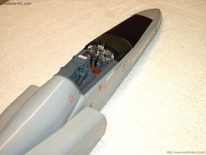
318 - USe this photo as a reference
when detailing the cockpit
| |
319 - This is a photo of a real F-20
cockpit. Use it to as details as desired
| |
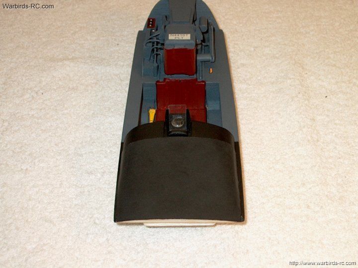
320 - Cockpit Walk Around - Pic 1
| |
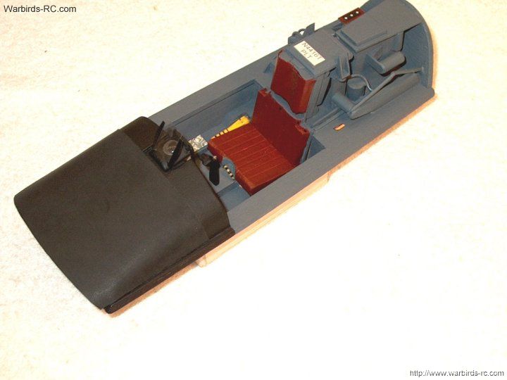
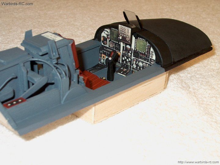
321 - Cockpit Walk Around - Pic 2
| |
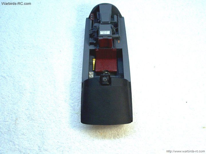
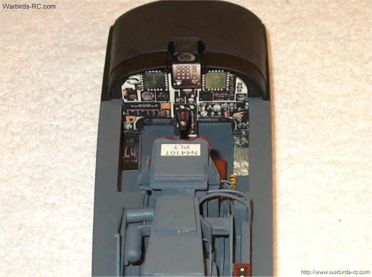
322 - Cockpit Walk Around - Pic 3
| |
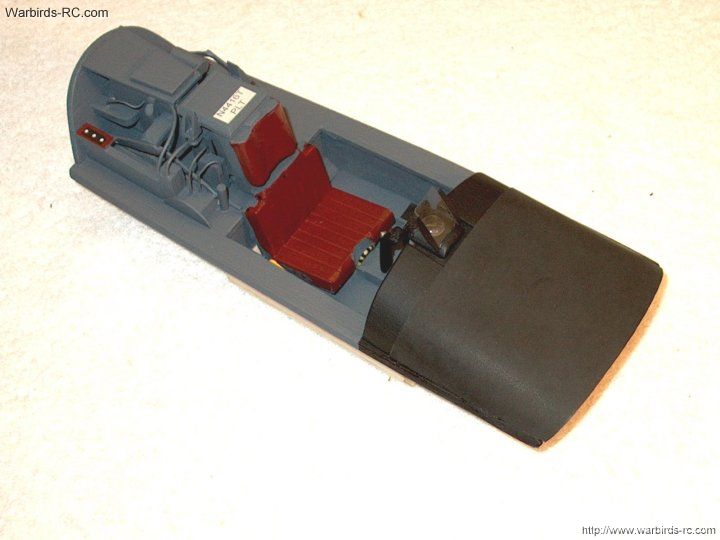
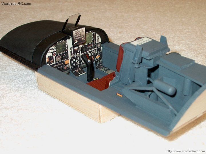
323 - Cockpit Walk Around - Pic 4
| |

324 - Cockpit Walk Around - Pic 5
| |
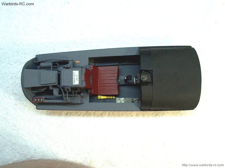
325 - Cockpit Walk Around - Pic 6
| |
326 - Cockpit Walk Around - Pic 7
| |
327 - Instrument Panel Walk Around - Pic 1
| |
328 - Instrument Panel Walk Around - Pic 1
| |
329 - Instrument Panel Walk Around - Pic 1
| |
330 - Install your cockpit in the fuselage
| |
331 - Rear view of the installed cockpit
| |
332 - Since I didn't have the sheets of
decal printed on clear peal like you will receive from the
mfgr, I had to make my own. Cut the F-20 out and apply it
| |
333 - Use tape to keep individual
letters in alignment
| |
334 - Place masking tape across the
bottom to apply the decals straight and even on both sides
| |
335 - Apply your rear decals as shown
| |
336 - Mask off the top deck and
paint it semi flat black. Flat black tends to crack,
so semi flat is a better choice. You can use a couple
light coats of dull-coat to flatten out the color
| |
337 - Use the cockpit when masking
to insure the tape lines up with the cockpit
| |
338 - Side view shows the cockpit with
paint and decals
| |
339 - Your model should have all
decals applied as shown
| |
340 - The F-20 Tigershark is
shown with detailing completed
| |
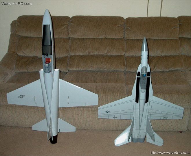
341 - The F-20 is huge in size compared to
the HET-RC FA-18
| |
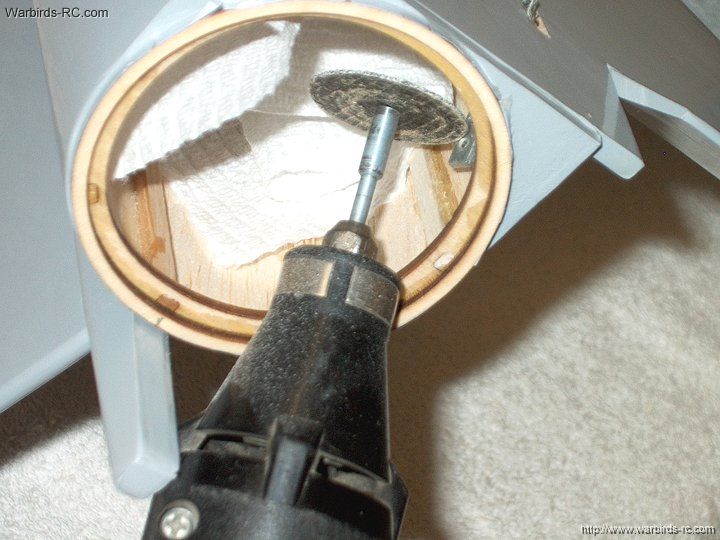
342 - There are many ways to
make a battery tray and this is just one of them. Note
that this method will add about 2 oz in weight. Cut two
1/8" planks of balsa and glue them in on each side of the
center spar to raise the deck. Shorten the The hook block
about 3/32" with a cutting wheel; you can see where the
newly installed balsa planks were carved out to make room
for velcro straps
| |
343 - Make a battery tray from 1/8"
plywood...you could probably shorten the front by 2"
from my pics to save some weight. Velcro is applied to
the battery packs and the plate bottom as shown, while
the straps hold the packs down to the plate
| |
344 - Epoxy the plate in place as shown.
the battery may have to recess into the rear opening for
proper balancing
| |
345 - Carve the former flush for the battery
| |
346 - Apply velcro to your battery | |
347 - I used two 2S Lipos that were
sandwiched to the velcro
| |
348 - Use a Y-connector of you use
2S packs. It is recommend you use sufficient packs for
your power requirements. These Kokam 3200's were rated at 64 amps
| |
349 - Install the battery in place.
Note that if you make one of these trays, it should be
made shorter at the front and extend slightly into
the rear for less weight and better balancing. This one was
a test tray, so it would be different if done again.
Also note the two black lines on each side of the velcro pad
at the bottom. This was a marker to place the packs so CG
would be at 67mm
| |
350 - Top view of the pack is shown
| |
351 - Paint and glue your canopy on
the cockpit using RC-56 canopy glue. Use tape to hold
it in place until the glue sets
| |
352 - Remove the tape and check the fit
| |
353 - Check the balance on your model
| |
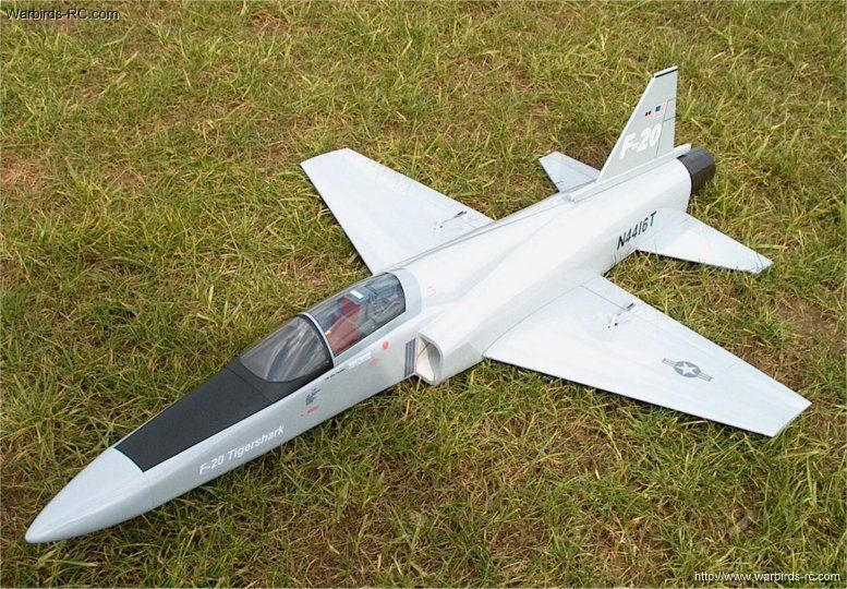
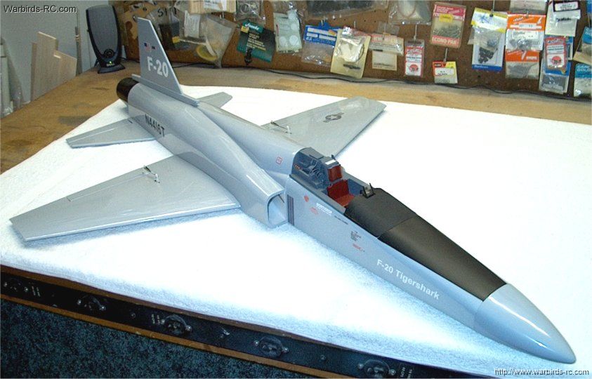
354 - The HET-RC F-20 Tigershark EDF Jet
| |

This Website and all documents herin are Copyright © 2012 www.scalerocketry.com -
All rights reserved.
| |