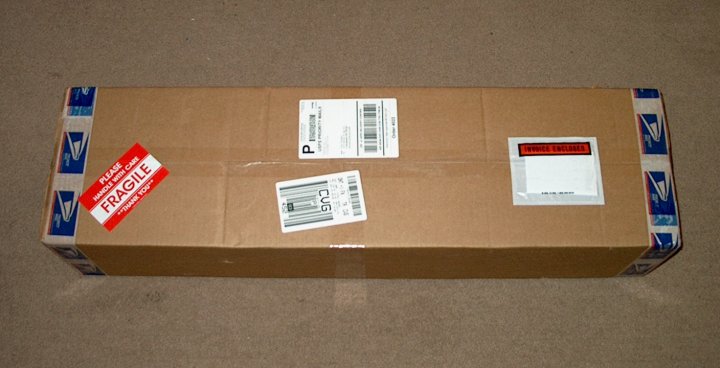
01 - The F-16 as it arrives well packed
from Markos at Warbirds-RC | |
02 - The model is double boxed and all
parts are wrapped for protection | |
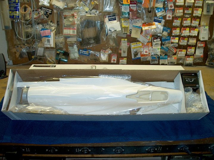
03 - The HET-RC F-16 Falcon ARF Minifan
480 Jet out of the box | |
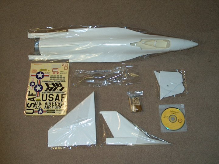
04 - The major components of the model. It
is very similar to the HET-RC FA-18 in construction and
covering | |
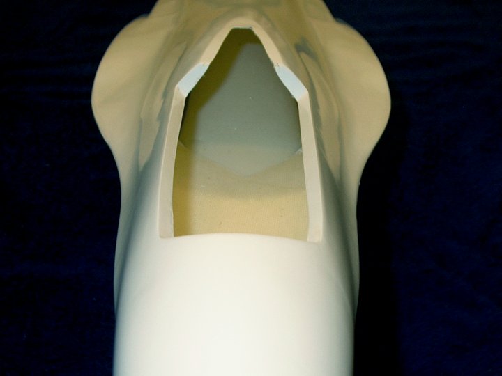
05 - Front view of cockpit area. The glass
work is very well done | |
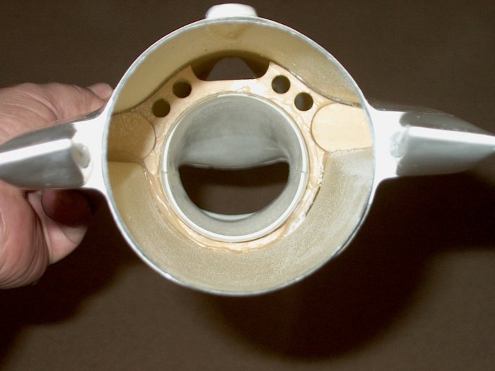
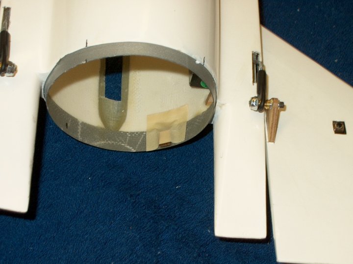
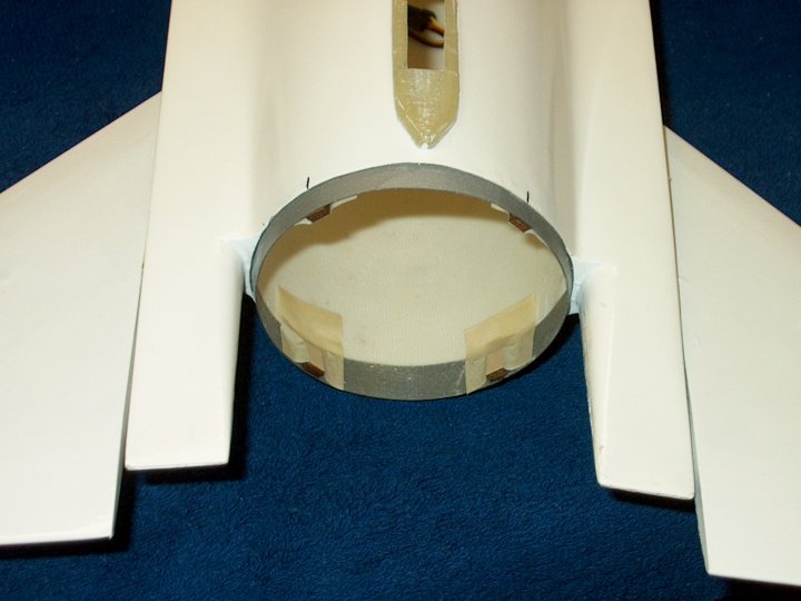
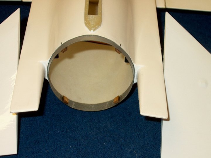
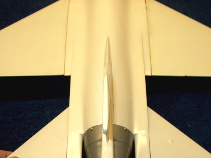
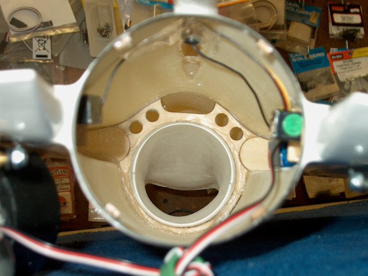
06 - Rear view showing pre-installed
Fiberglass Intake and formers | |
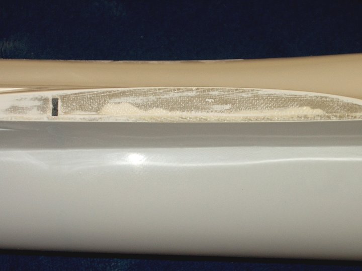
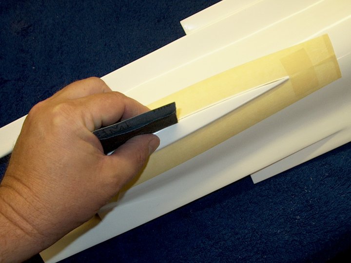
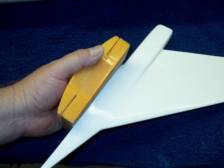
07 - Construction: Sand the wing saddle on
the fuselage for good glue purchase
| |
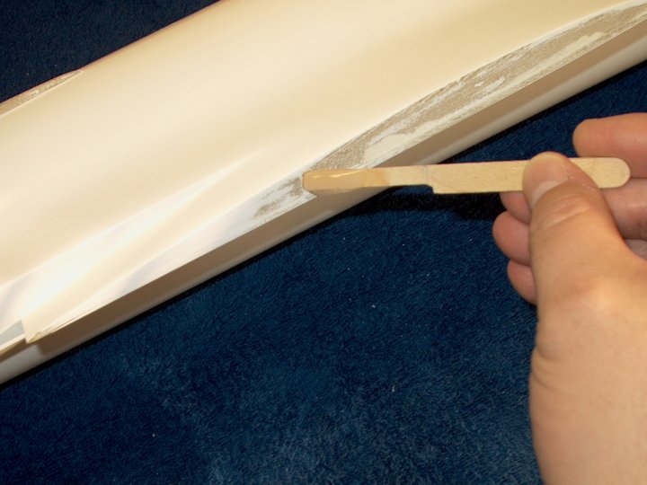
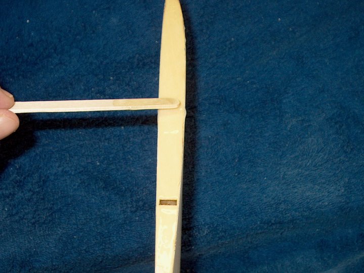
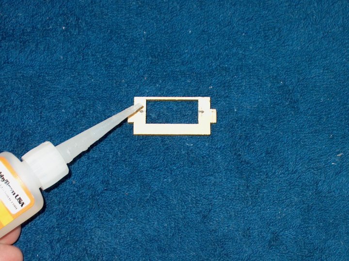
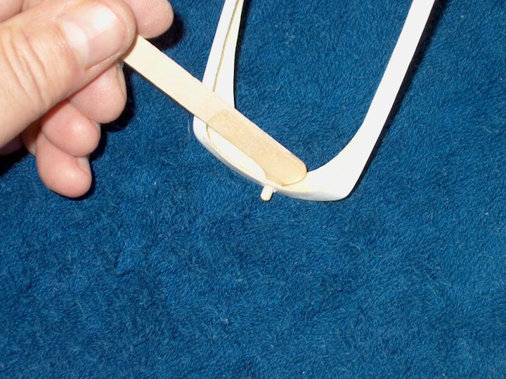
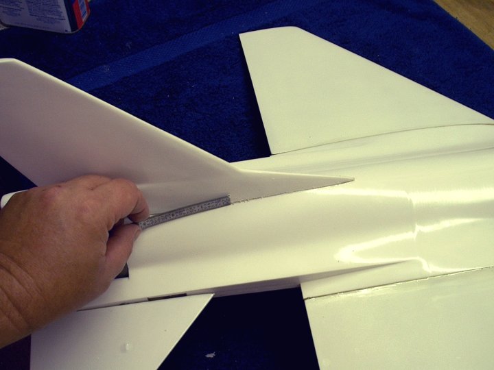
08 - Five Minute Epoxy is applied in the
wing spar hole using a cut down mixing stick to fit the
slot | |
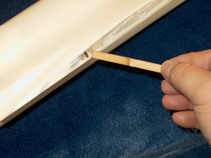
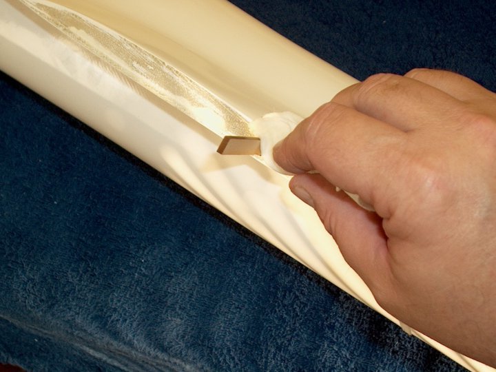
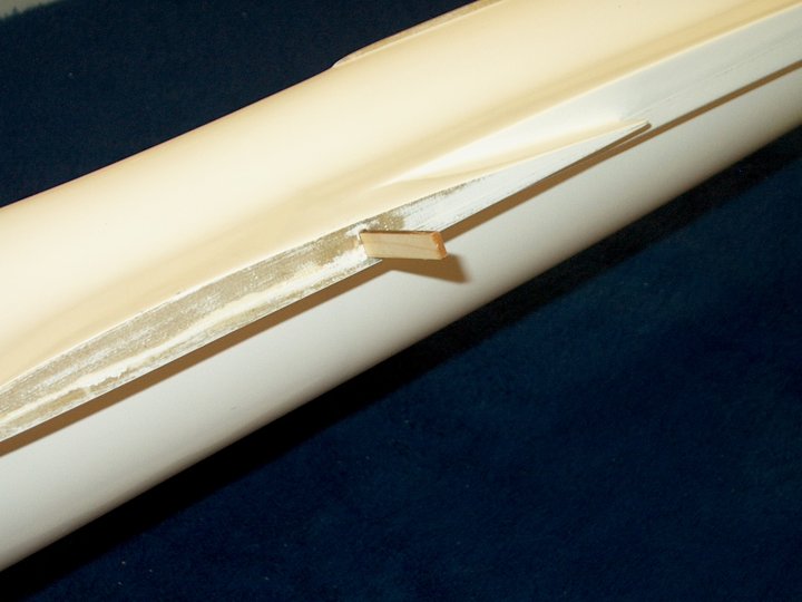
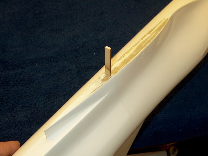
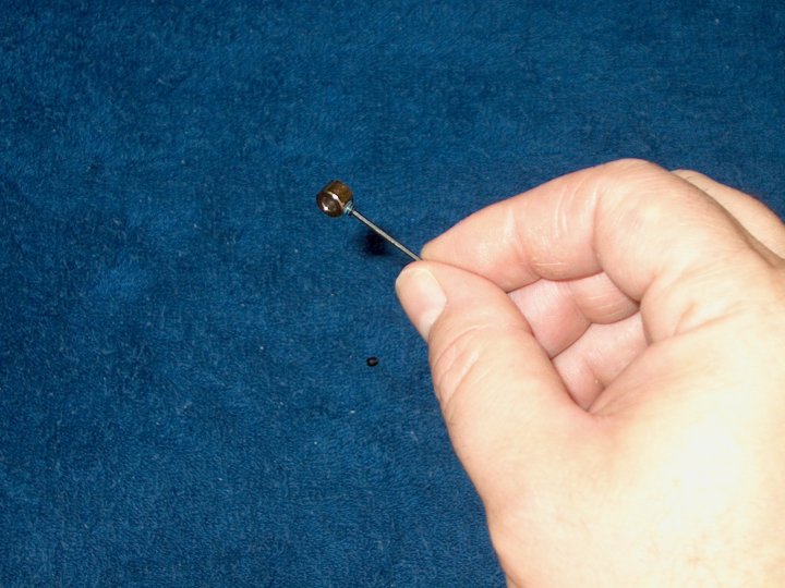
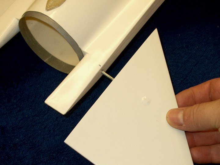
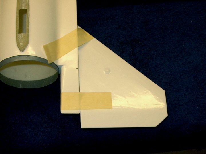
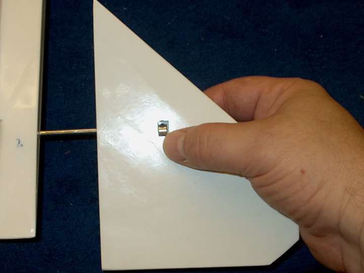
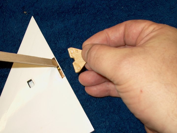
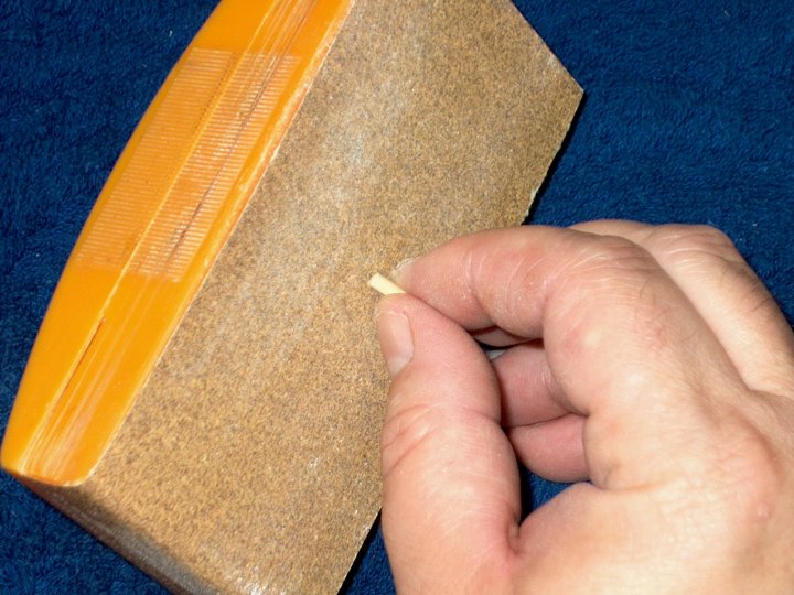
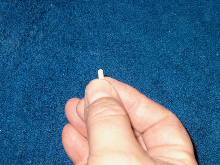
09 - Next, insert a wing spar until it
bottoms out in the slot | |
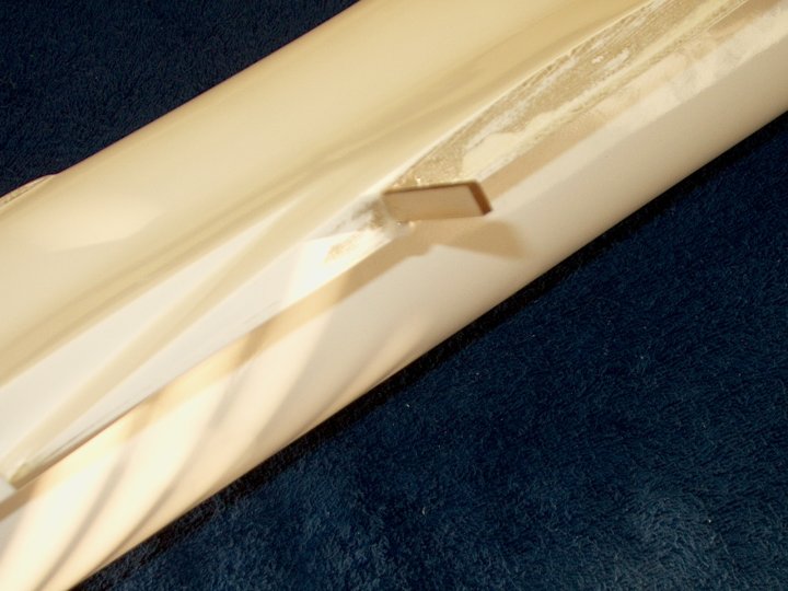
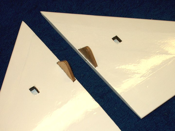
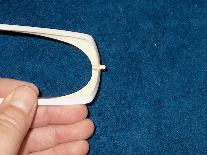
10 - Spar shown installed
| |
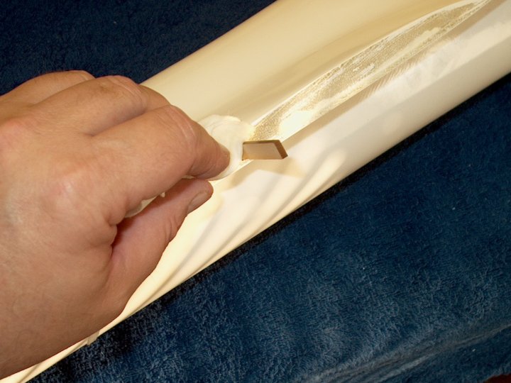
11 - Clean up excess epoxy with some paper
towels and denatured alcohol | |
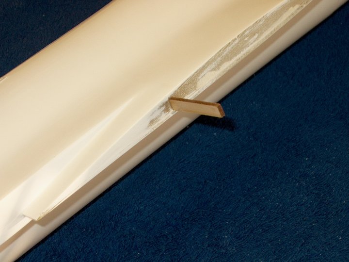
12 - Spar installation shown
completed | |
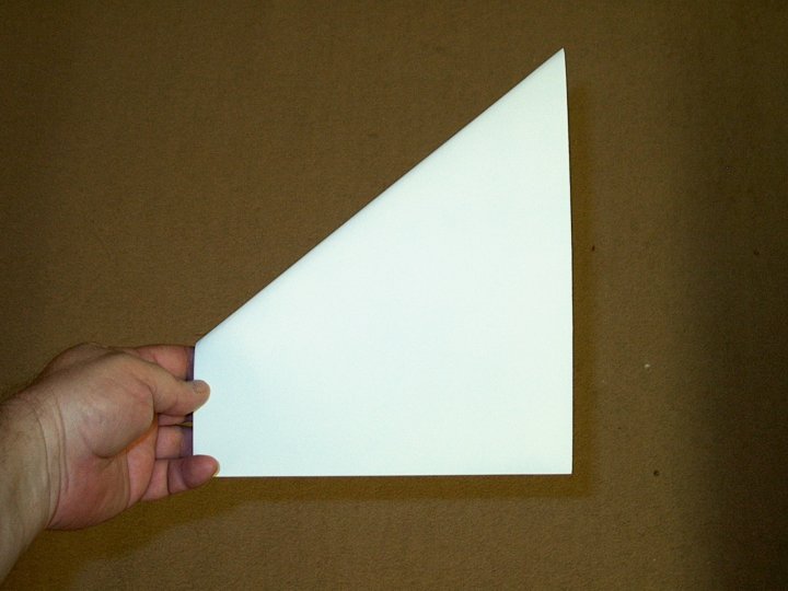
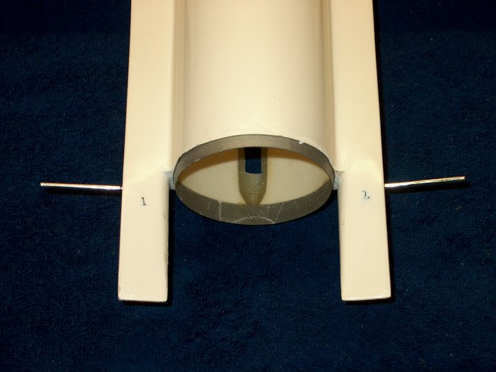
13 - There is a left and right wing. The
side with less curve is the bottom, so mark them "left" and
"right" | |
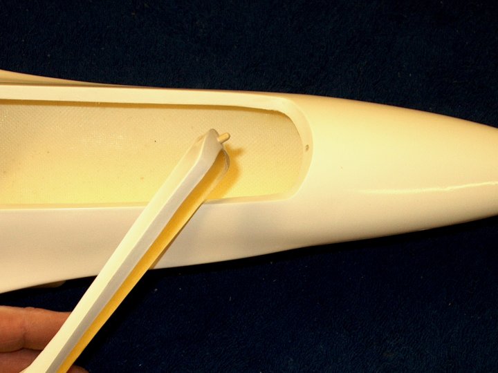
14 - The wing is placed over the spar and
adjusted so it is centered in the rear and the front of the
fuselage. This will adjust the spar to the correct position.
Carefully remove the wing and let the spar glue set
| |
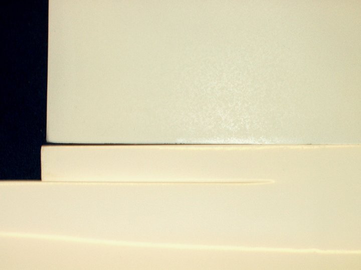
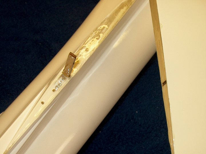
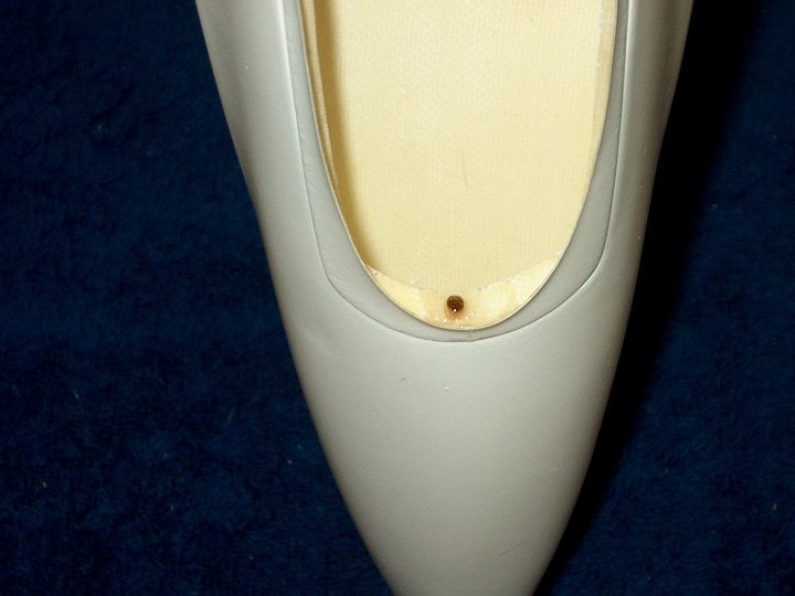
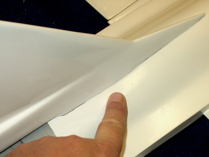
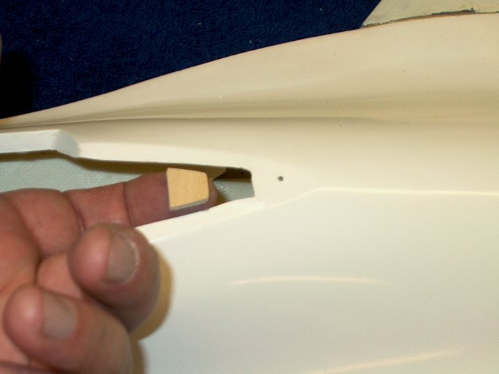
15 - The wing shown installed and flush in
the front of the fuselage shows a gap at the rear. This will
be filled with Epoxy when the wing is mounted
| |
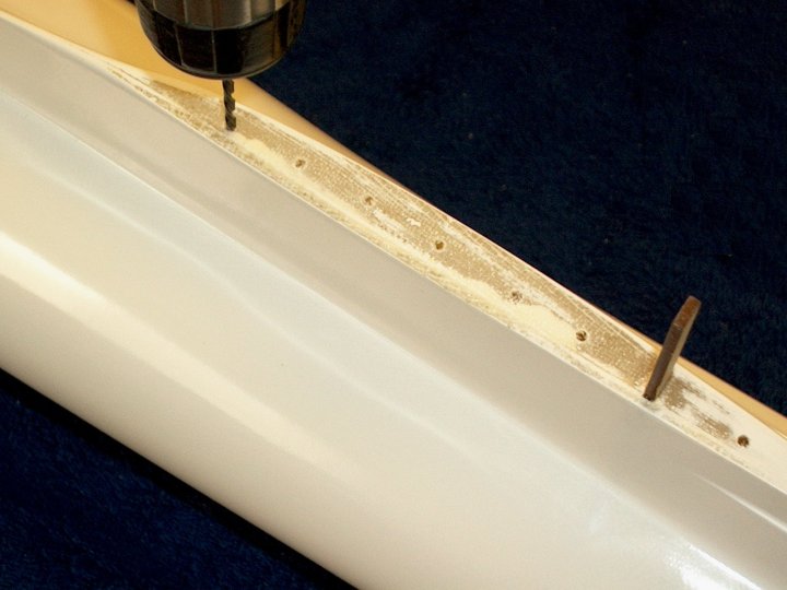
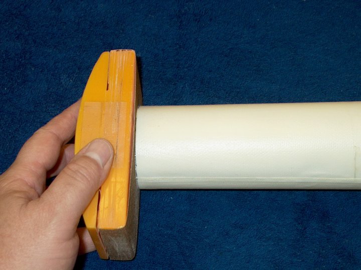
16 - A 1/8" drill bit is used to make some
holes in the fuselage. This will allow the epoxy to create
"rivots" inside the wing saddle for a stronger joint. Lightly
sand after drilling to remove burrs
| |
17 - Fifteen minute Epoxy is applied to
the wing root | |
18 - Fifteen minute Epoxy is applied to
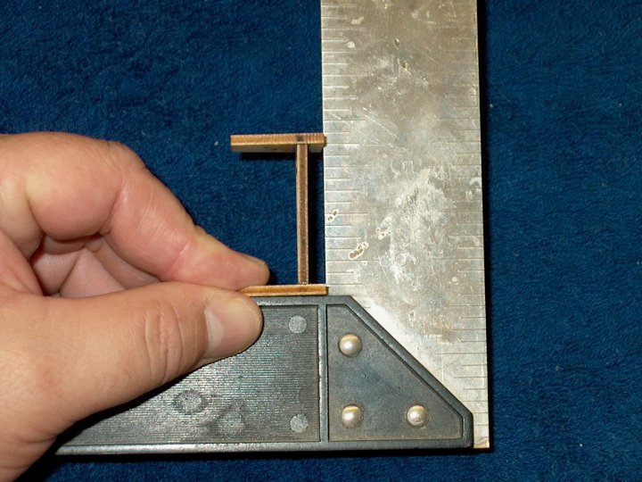
the wing root. | |
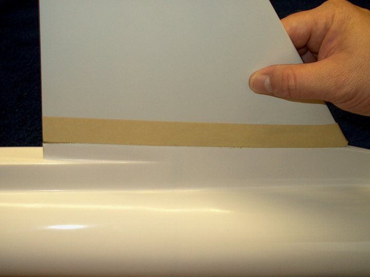
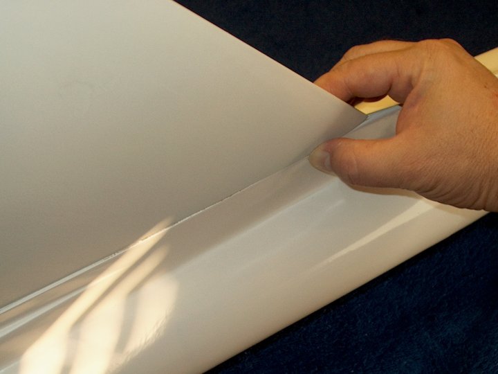
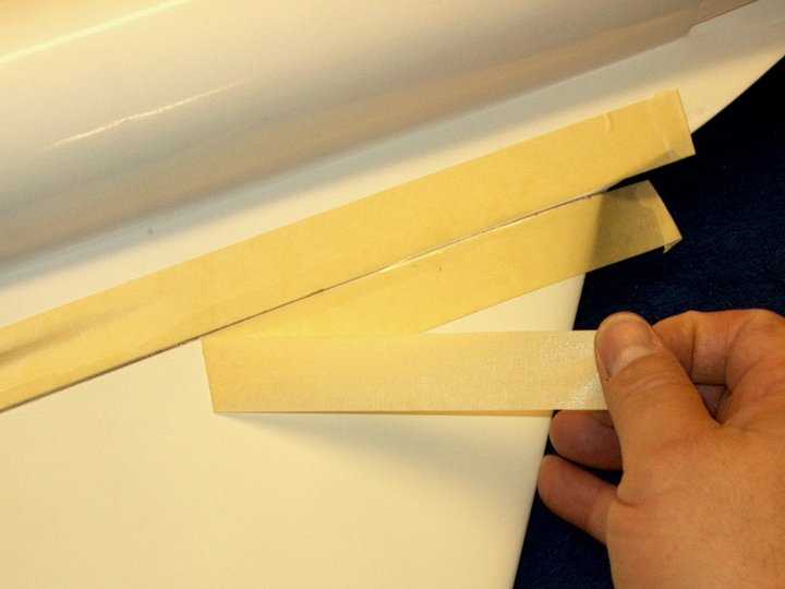
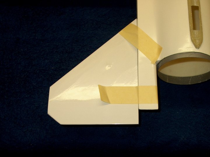
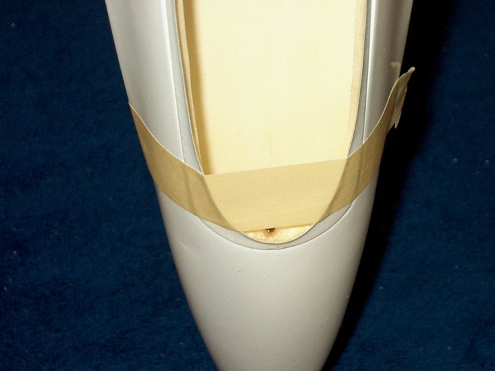
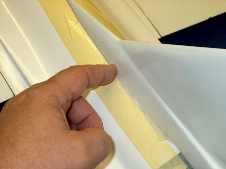
19 - The wing is set in place. If you
fiberglassed your wing, masking tape is used to keep excess
epoxy from adhering to the finished surface. Make sure the
wing is centered and the bottom of the wing is flush with the
root molding of the fuselage. Keeping the bottom of the wing
flush with the bottom of the fuselage will insure correct
incidence without any twist for the wing position.
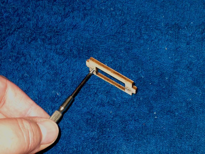
| |
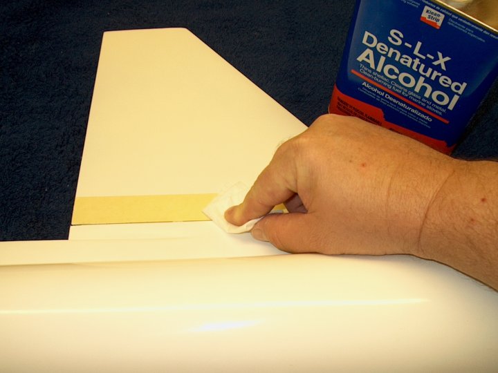
20 - Denatured alcohol is used to remove
the excess epoxy | |
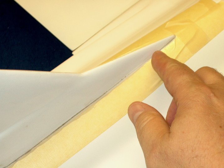
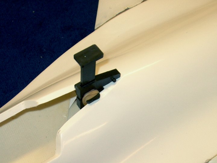
21 - The front of the wing is centered and
held in place with masking tape. The rear is centered and held
in place with a clamp and left to set
| |
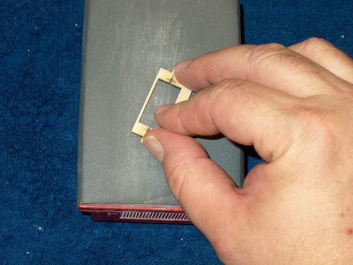
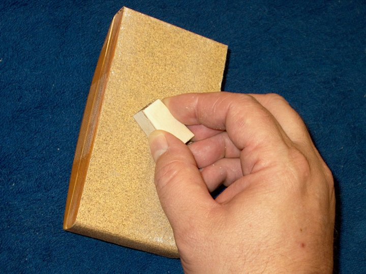
22 - The other wing saddle is sanded for
better glue purchase. A small piece of 60 grit sandpaper makes
quick work of it, but be careful not to oversand
| |
23 - Epoxy is applied to the spar slot
with a cut back mixing stick | |
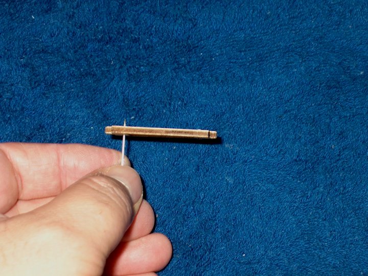
24 - Epoxy is applied to the spar and the
wing spar is installed until it bottoms out in the slot
| |
25 - Excess glue is cleaned up with
denatured alcohol and a paper towel
| |
26 - Spar is installed
| |
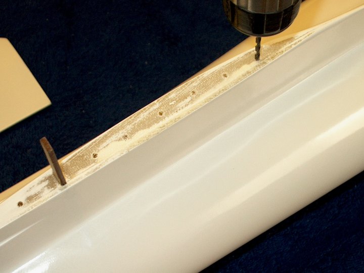
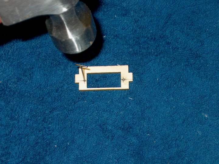
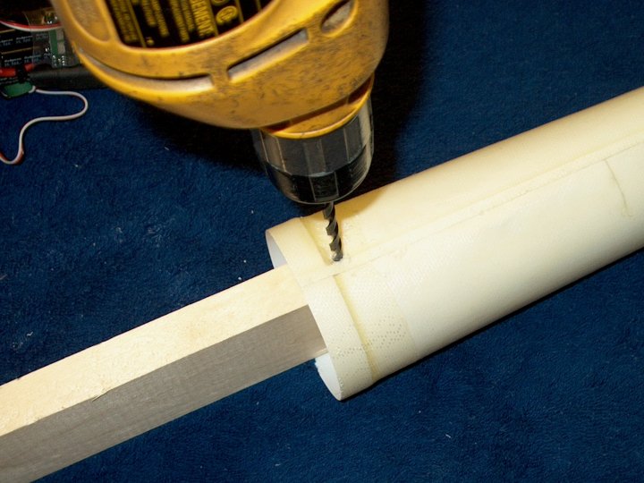
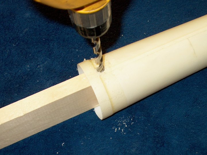
27 - Wing is placed in position and
centered in the front and back to correctly position the spar,
then it is carefully removed before the epoxy sets, then the
spar is drilled for rivot holes | |
28 - Epoxy is applied to the wing
root | |
29 - Next epoxy is applied to the fuselage
wing saddle and spar | |
30 - The wing is installed on the saddle
and centered. Excess epoxy is removed with denatured alcohol
and a paper towel. Then tape is used to keep the front of the
wing centered and the bottom of the wing flush to the fuselage
root while a clamp keeps the rear centered until the epoxy
sets | |
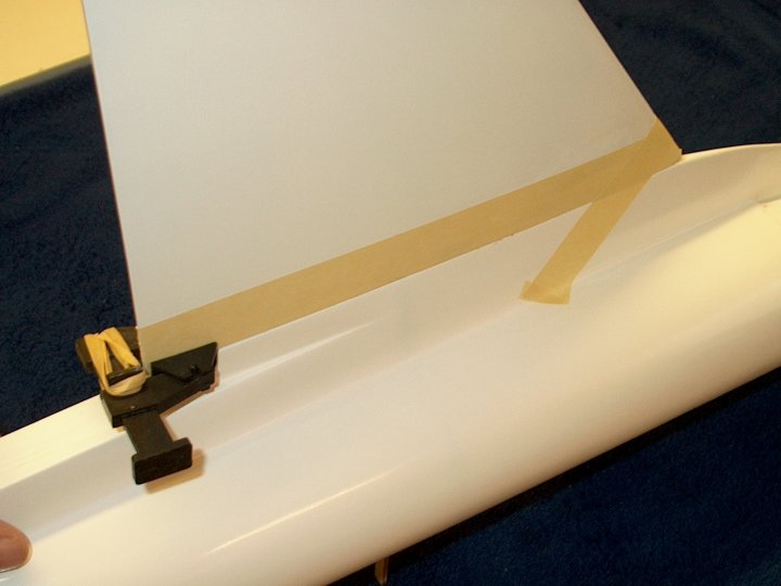
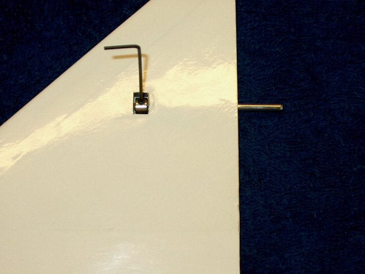
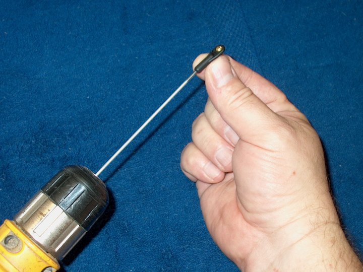
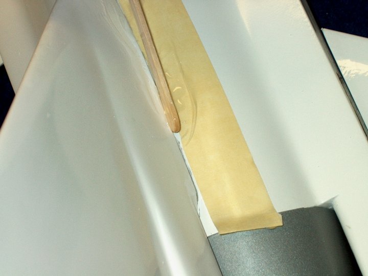
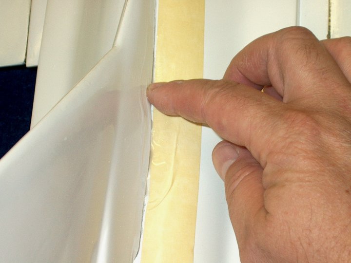
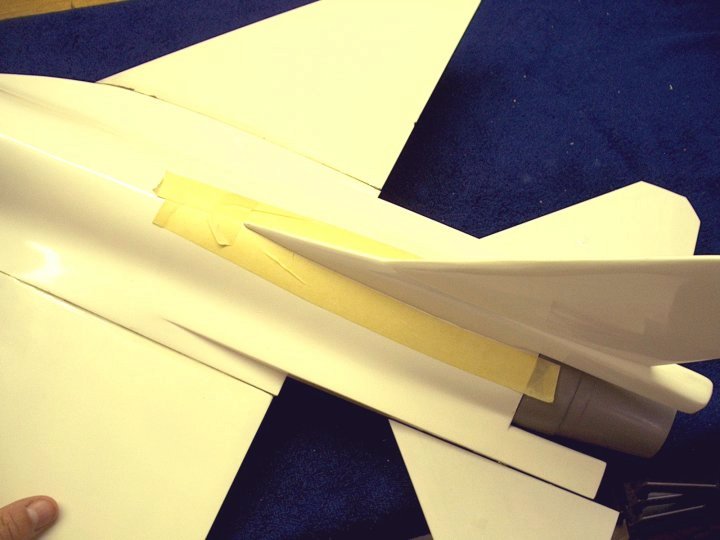
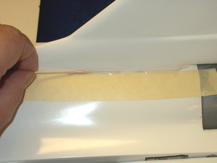
31 - Epoxy is applied to the joint as a
fillet. A toothpick is used to apply it and the tape was place
on the surfaces to catch the overflow
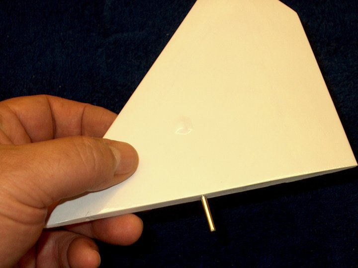
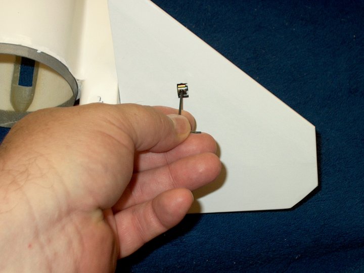
| |
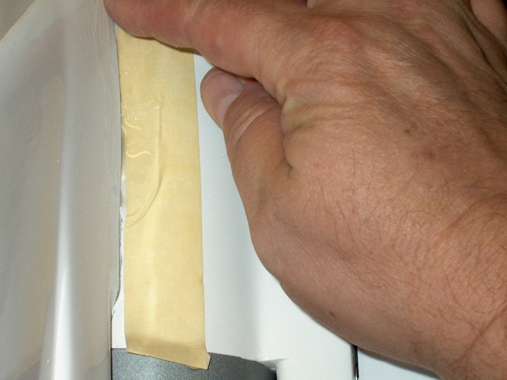
32 - The excess epoxy is wiped off and
overflow lands on the tape | |
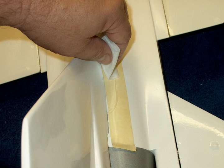
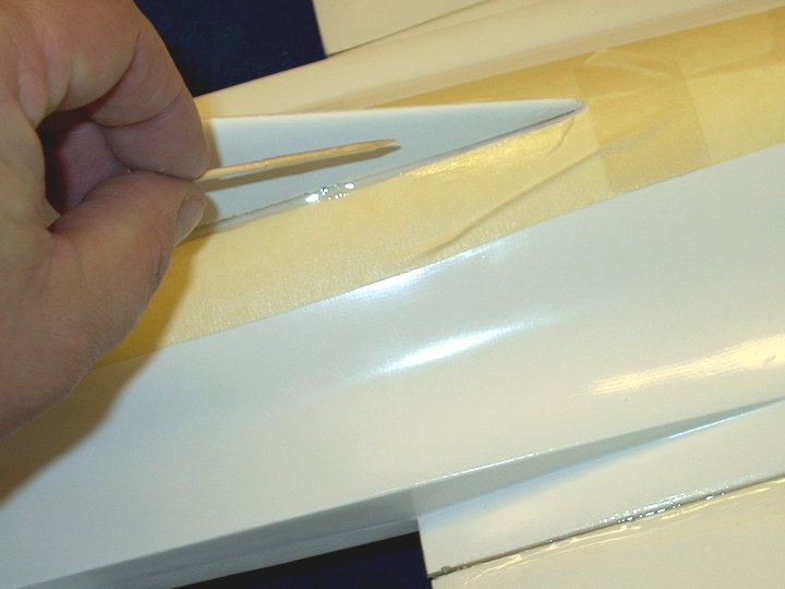
33 - The tape is removed, revealing a
clean joint. Repeat and do the same on the other side of the
model | |
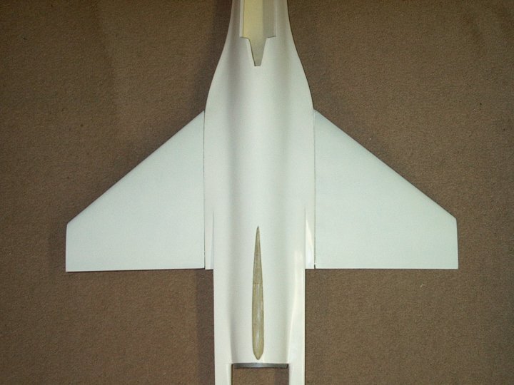
34 - Wings are shown installed on the
fuselage | |
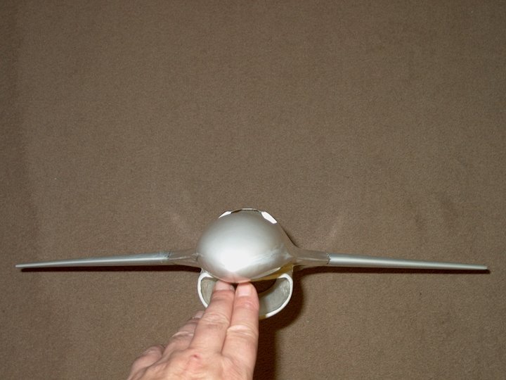
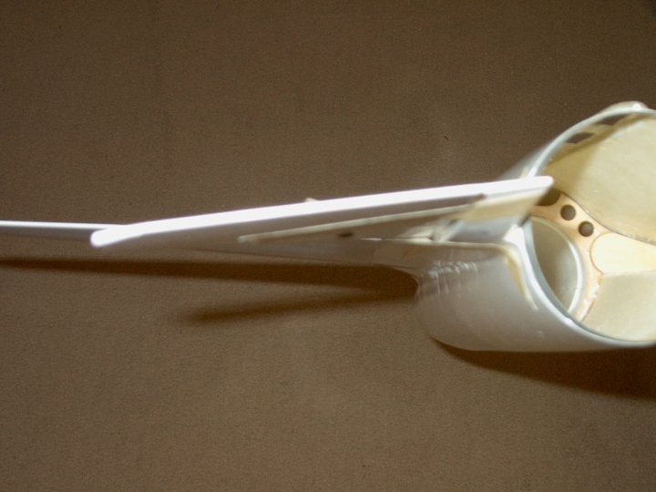
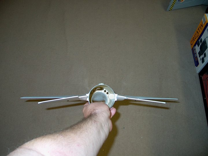
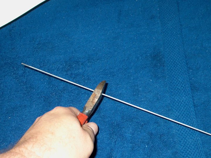
35 - Front view of wing installation shows
wings with a couple of degrees on anhedral. This was due to
the design of the fuselage | |
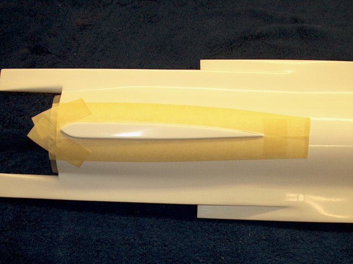
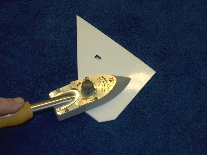
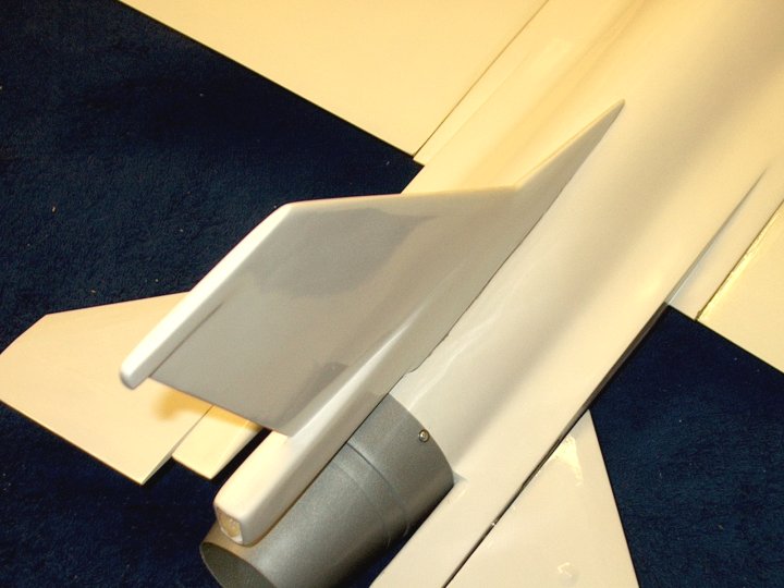
36 - The vertical stabilizer area of the
fuselage is taped off so sandpaper does not mar the
finish | |
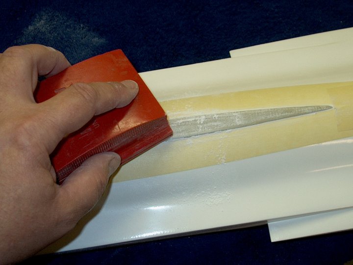
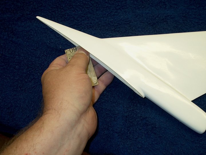
37 - Sand the sides of the saddle with
80-100 grit sandpaper. Be very careful as to not oversand as
you could cut through the glass | |
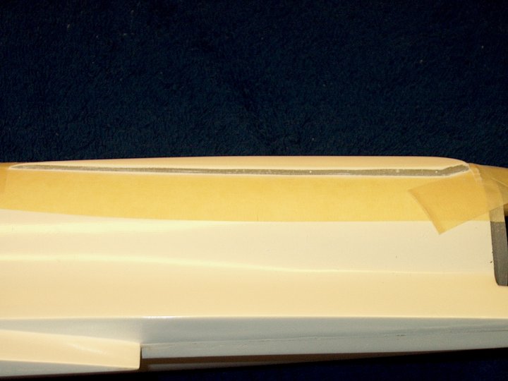
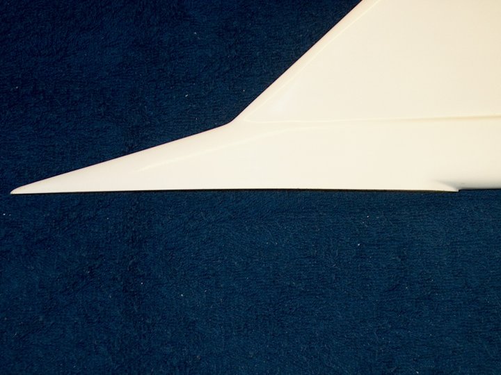
38 - Side view shows edges sanded and
ready for epoxy | |
39 - The top outside edges were sanded so
any excess glue would adhere well and form an internal fillet.
While it is not necessary, the entire top of the saddle area
was sanded in the pic | |
40 - Stab area sanded. Be careful to not
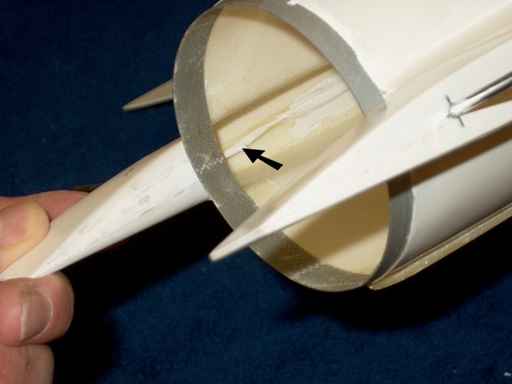
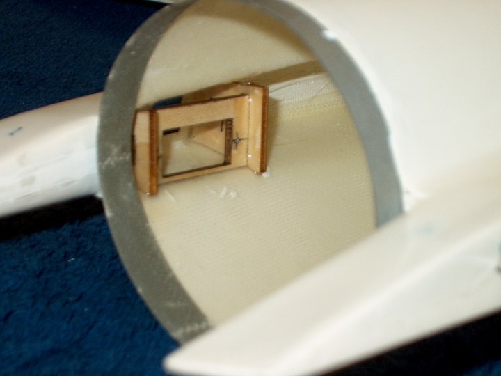
oversand...if you do, simply apply a coat of epoxy on the
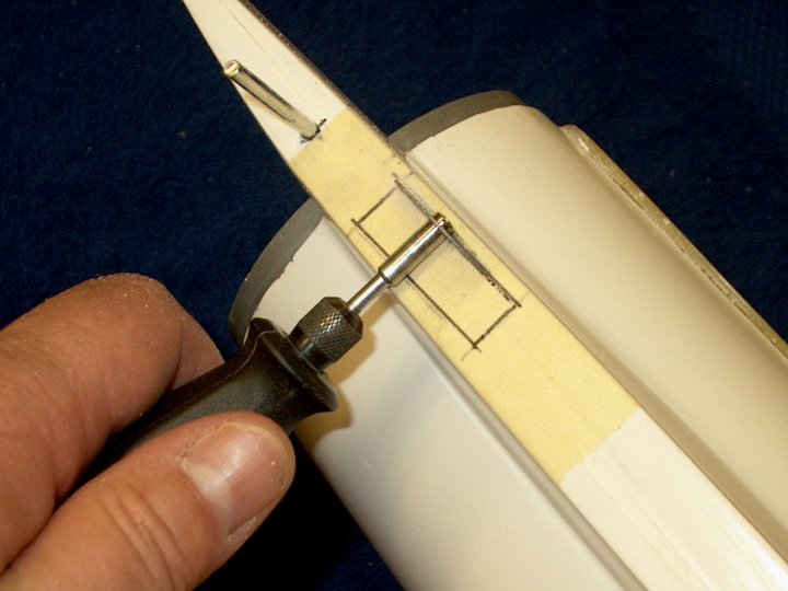
inside area of the fuselage to strengthen
| |
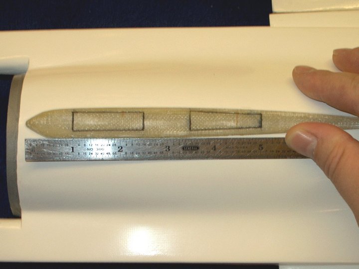
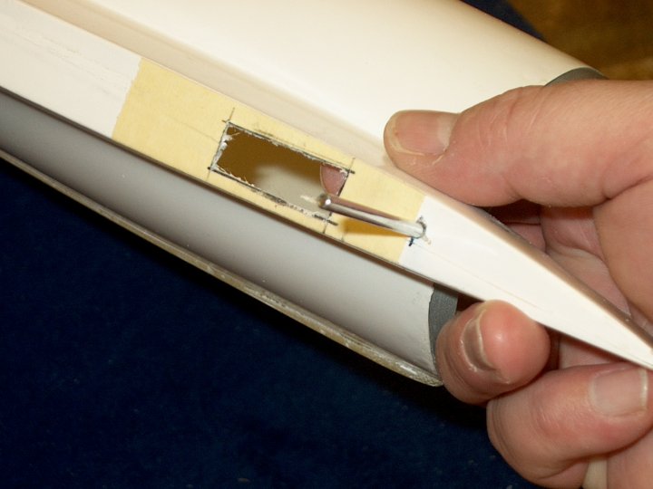
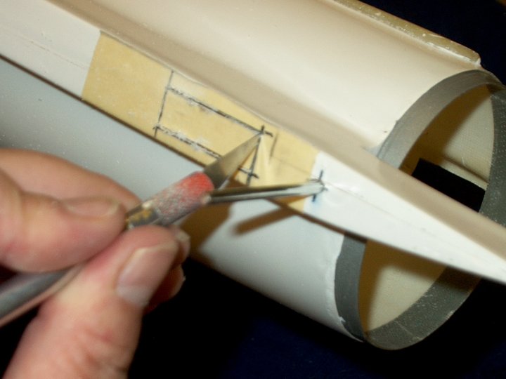
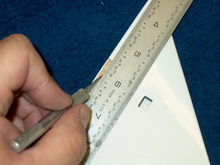
41 - Marks were made in order to cut two 1
1/2" long slots in the vertical stab area that are used for
both cooling and the receiver antenna
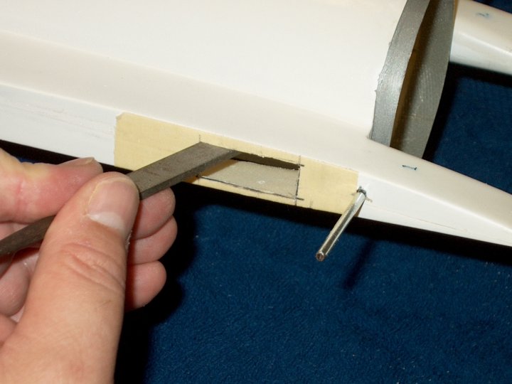
| |
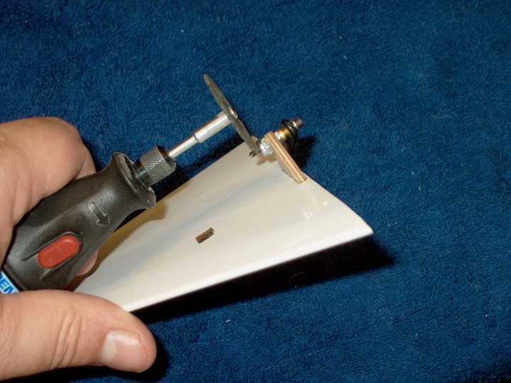
42 - A Dremel with a stone cutting wheel
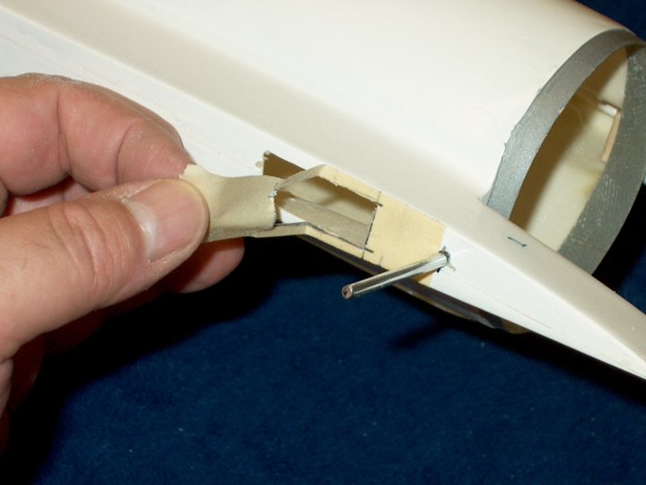
was used to open the slots | |
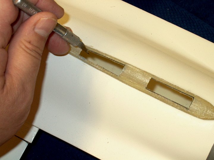
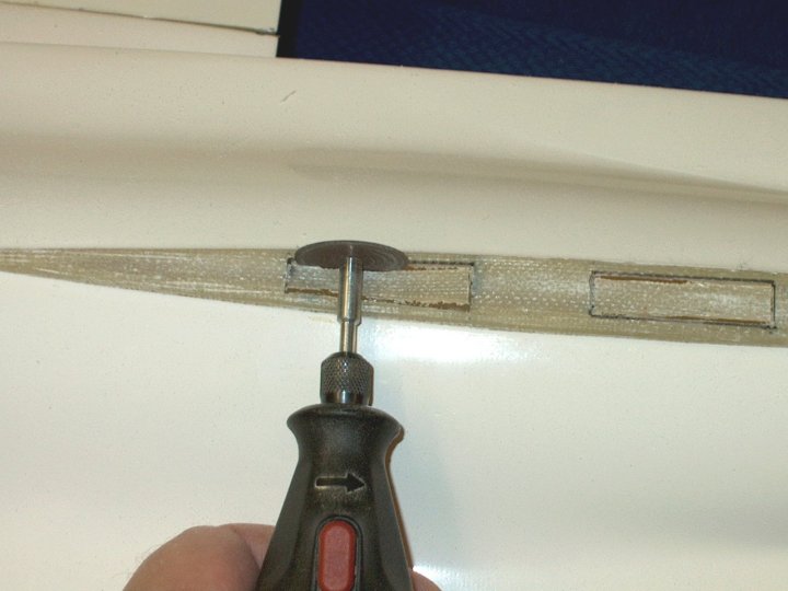
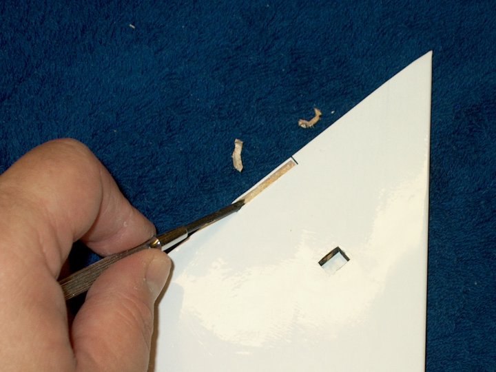
43 - A hobby knife is used to clean the
corners and remove large burrs | |
44 - Some 400 grit sandpaper is used to
smooth the edges inside and out | |
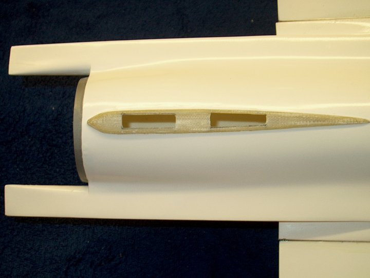
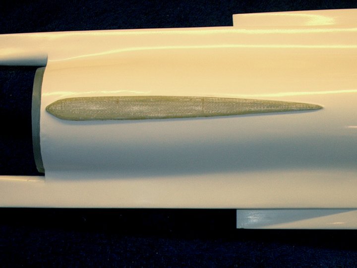
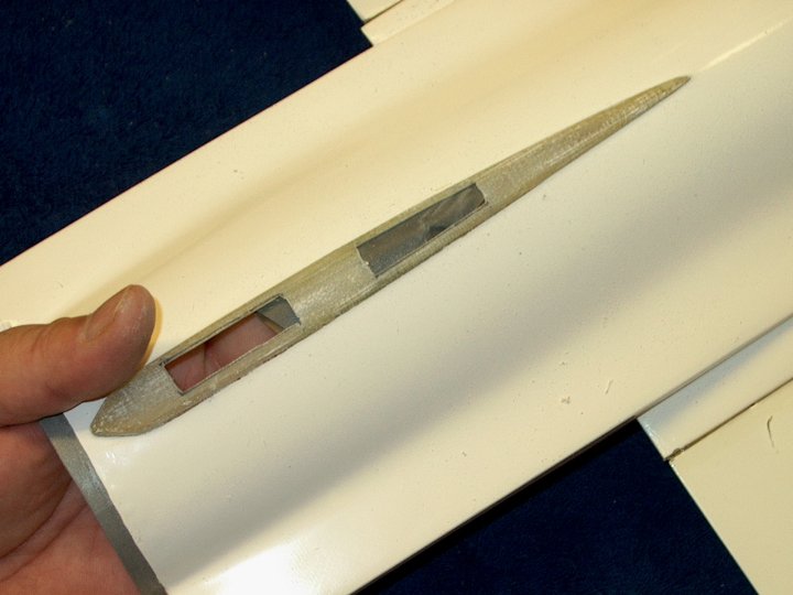
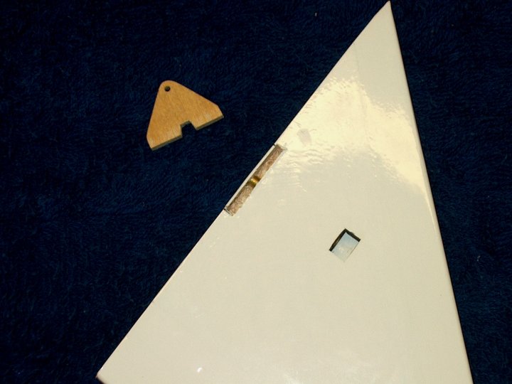
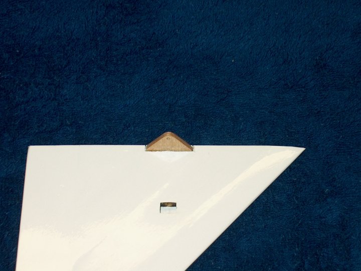
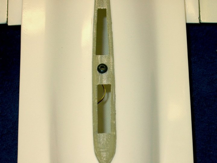
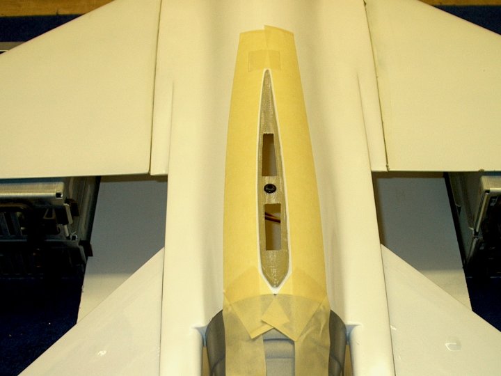
45 - The two slots are shown finished.
This completes the Vertical Stab pre-assembly
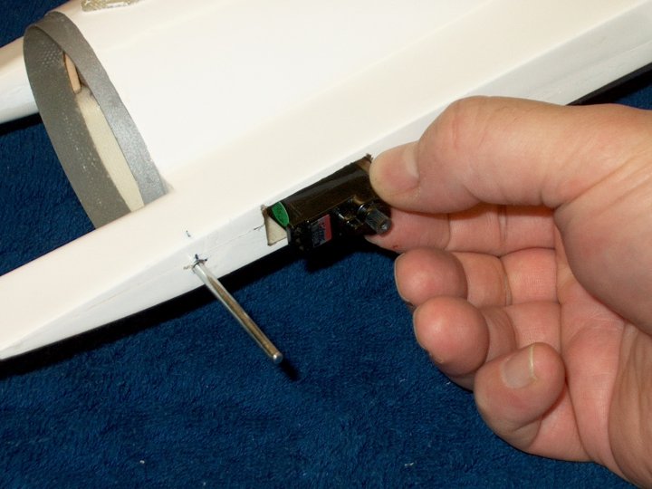
| |
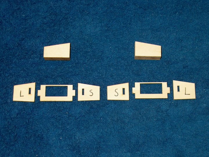
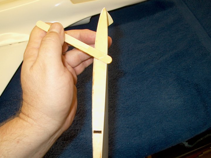
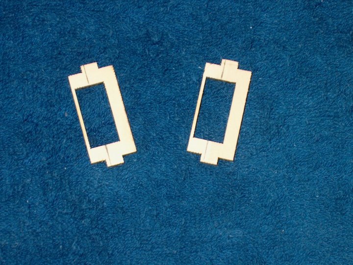
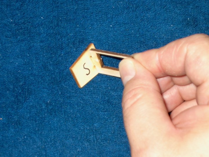
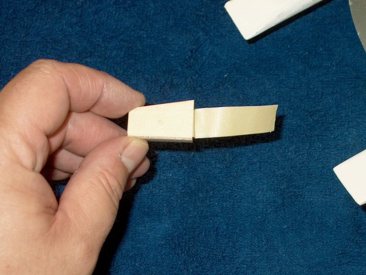
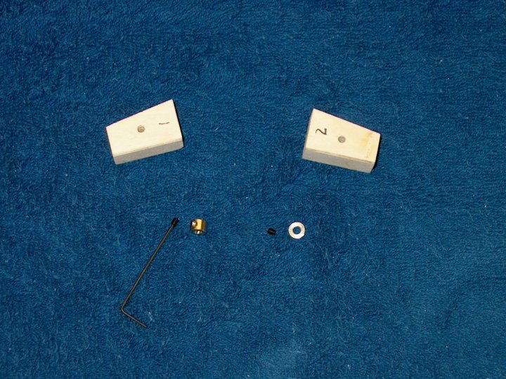
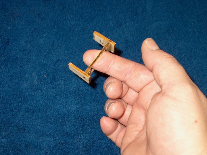
46 - The wood pieces that are needed for
Taileron assembly. Make sure you make two opposite/mirrored
trays, one for the left and one for the right. The side plates
are labeled S for Short and L for Long with the long side
facing the front of the fuselage when installed
| |
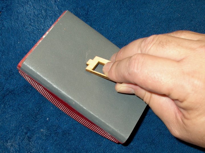
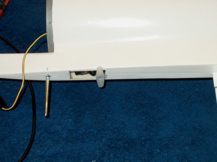
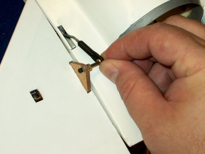
47 - The two ends of both servo trays were
lightly beveled with 400 grit so they could fit in the slots
of the side plates | |
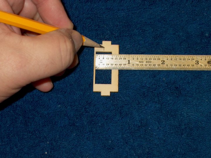
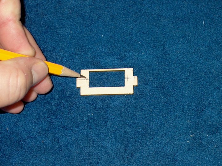
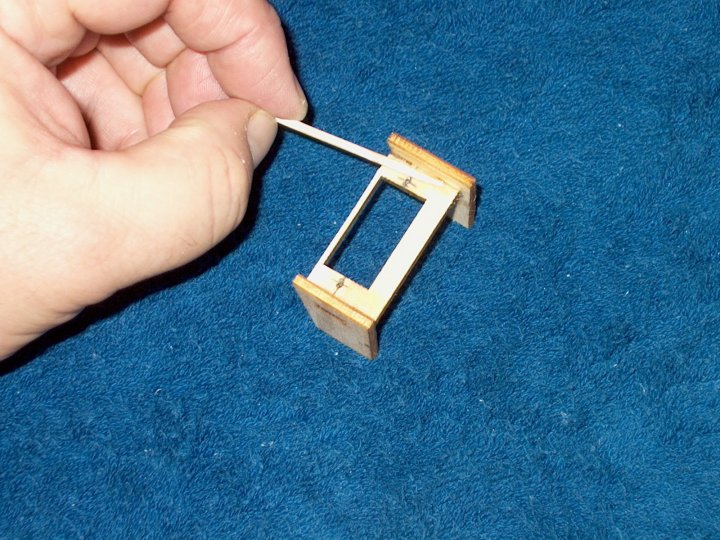
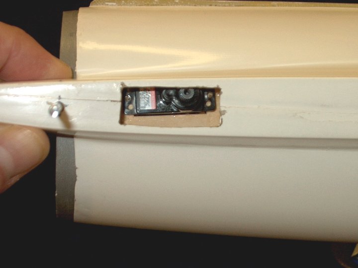
48 - Use a ruler to mark center on the
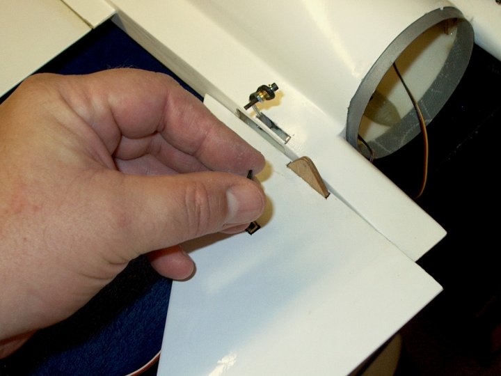
servo tray | |
49 - Mark both trays with a center line
for your servos | |
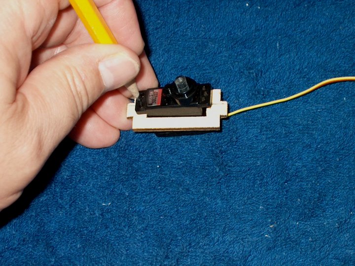
50 - The HS65 servos are a perfect fit and
were inserted in their tray to mark for drilling. The was some
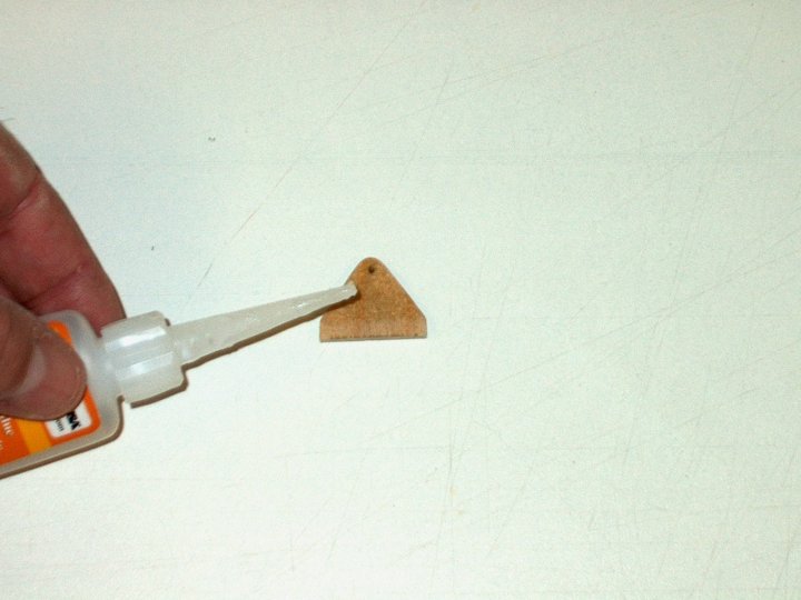
play in the tray, so the servo was pushed flush against the
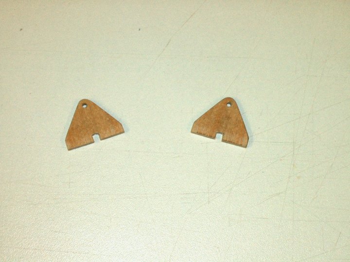
left side, then holes were drawn on both ends. It was then
pushed flush to the right side and marks were made
again | |
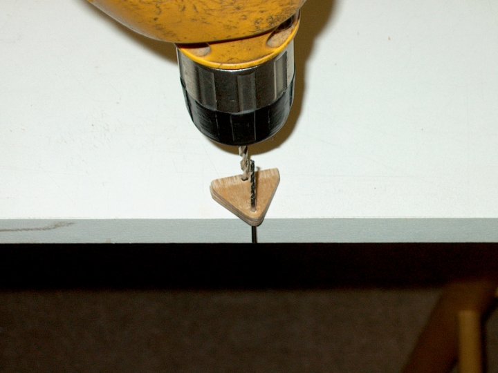
51 - You can see the two marks made at
each end. Draw a line between them for a perfect center
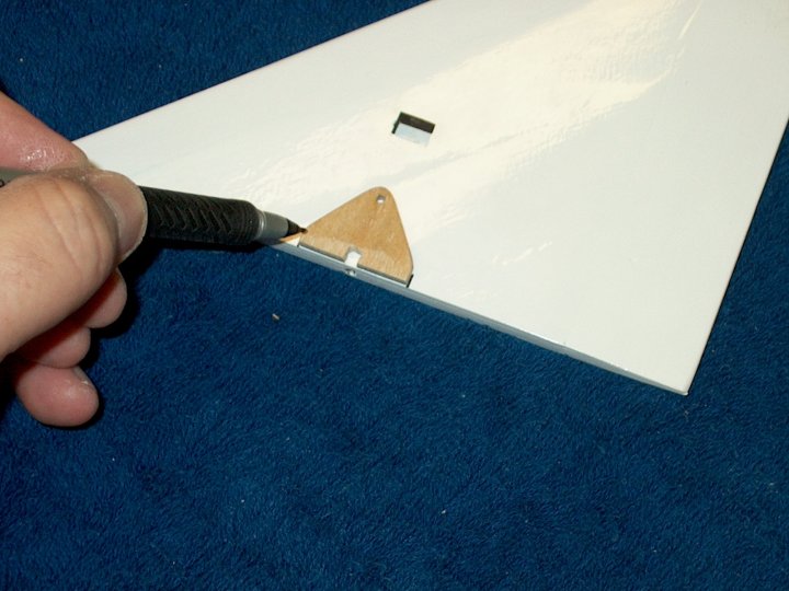
| |
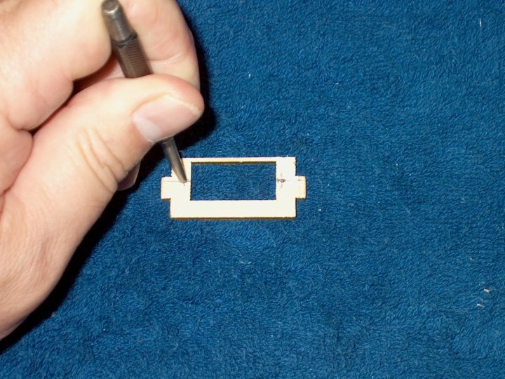
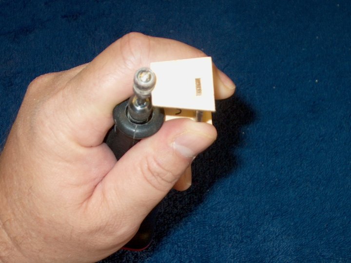
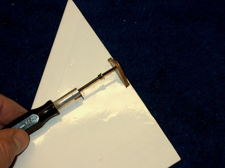
52 - Use a punch to mark where the holes
need to be made | |
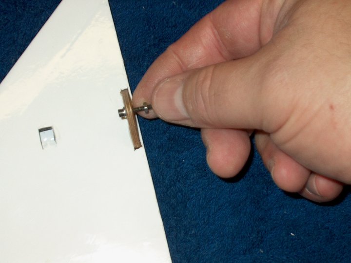
53 - Use thin CA to coat each mounting
hole area on both sides of the tray. This will prevent
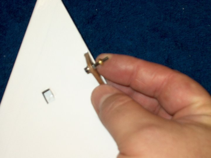
cracking and splintering when drilled
| |
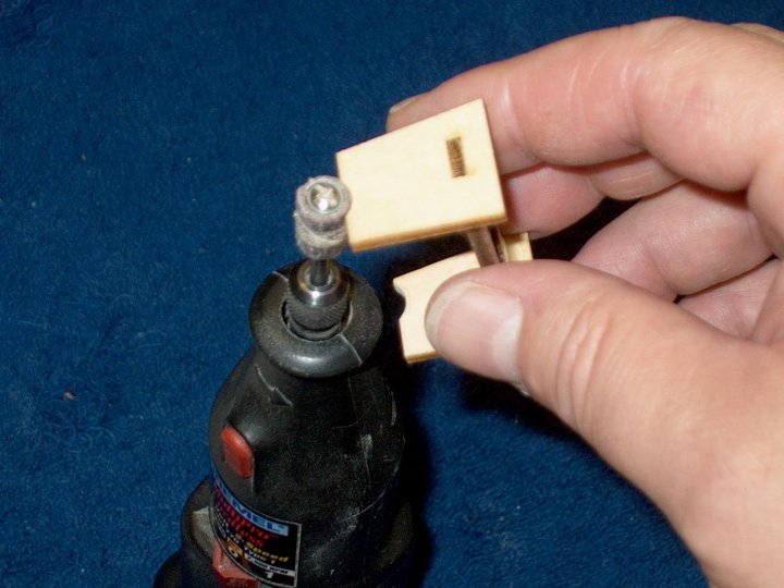
54 - The tray is lightly sanded to smooth
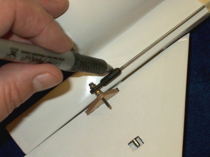
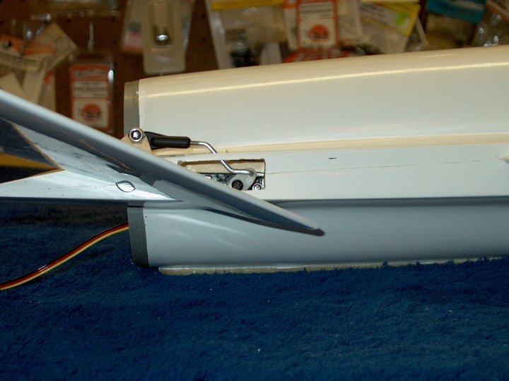
out the CA glue area | |
55 - You need a hobby drill smaller than
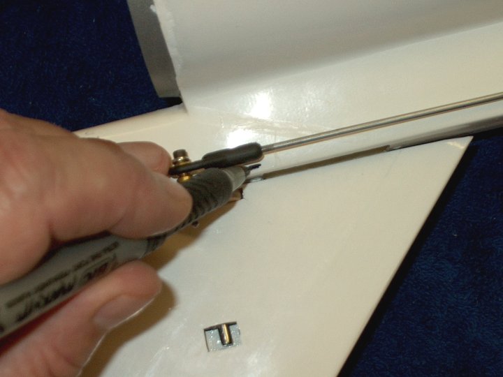
the standard US 1/16" because the servo mounting screws are so
small, so I found that a medium hobby push pin would work. Use
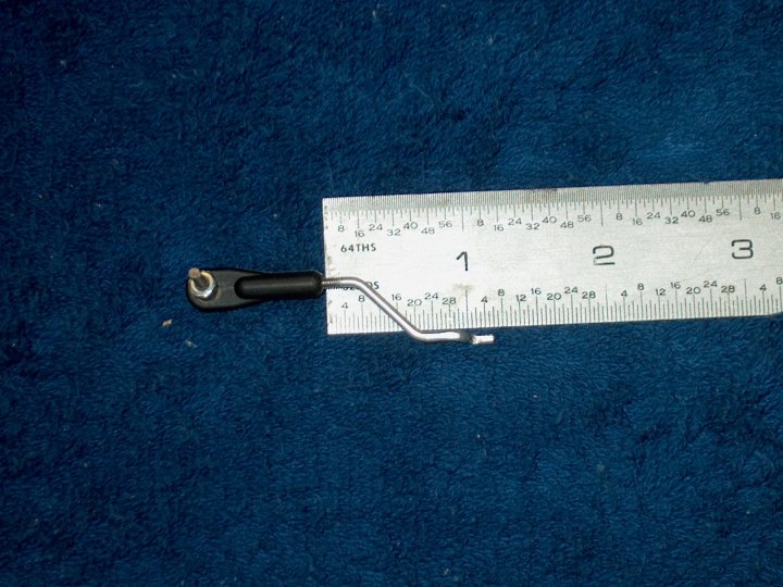
a hammer and carefully drive it through the tray like a nail,
being careful to keep it straight. Remove the pin and insert
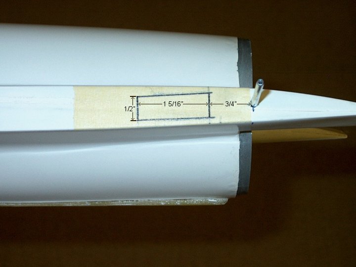
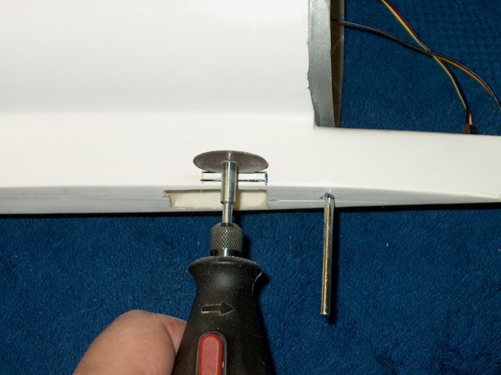
it in the back side of the tray to open the hole a bit
| |
56 - Photo shows the pin driven through
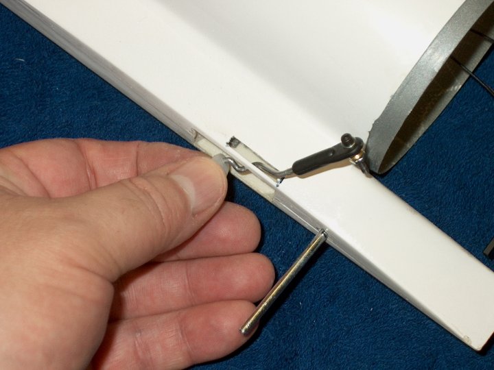
the plate | |
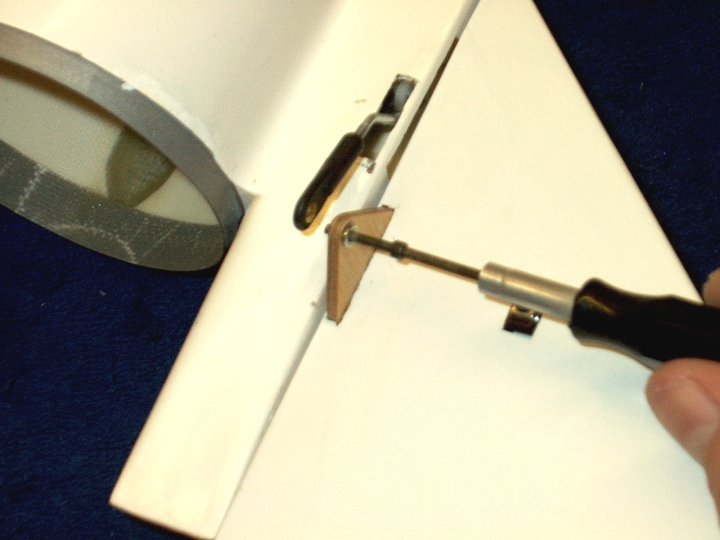
57 - Servo mounting screws are installed
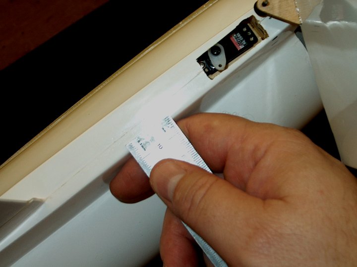
to "cut" threads in the wood | |
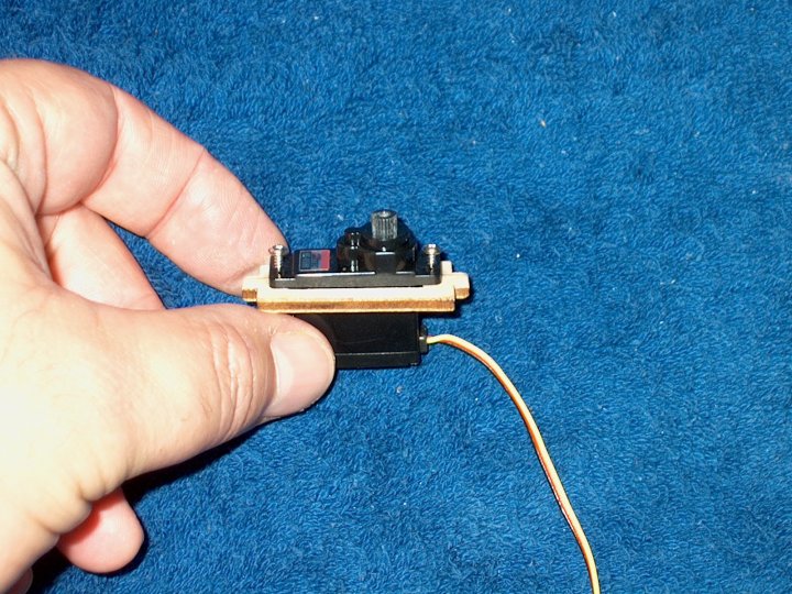
58 - Temporarily install the servo...the
screws should match up with the holes and the servo should be
centered in the tray | |
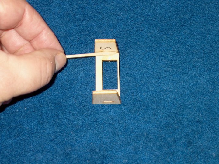
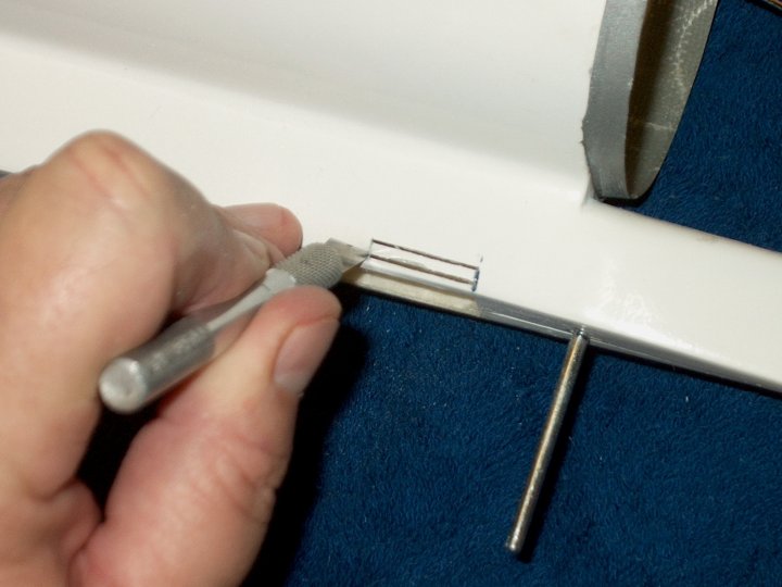
59 - Insert a tray into a side plate. Note
that the thin side of the tray faces upward toward the angled
side of the plate. Do not push in all the way
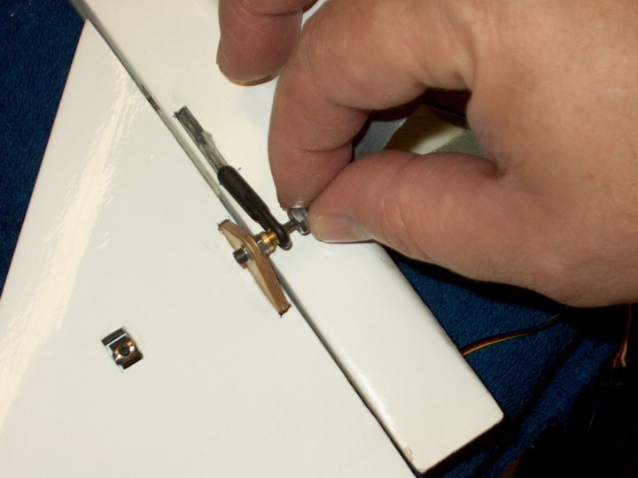
| |
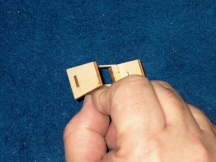
60 - Install the other end of a tray into
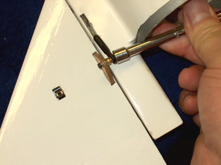
a plate, with the angled side of the plate facing the thin
side of the tray. Be sure to use a short plate on one end and
a long plate on the other end | |
61 - Mix some 5 minute epoxy and use a
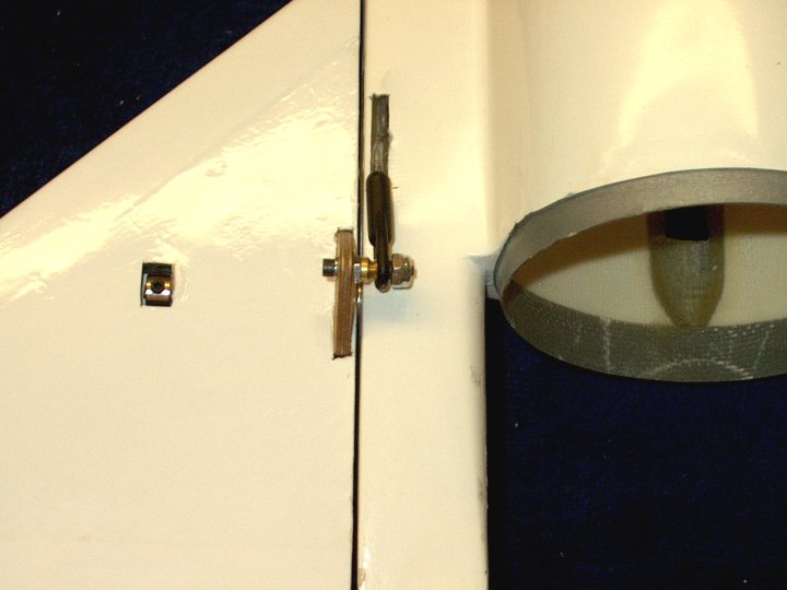
toothpick to roll it into the joint at both ends
| |
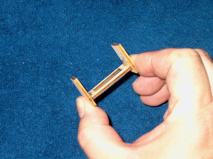
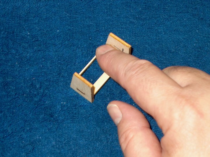
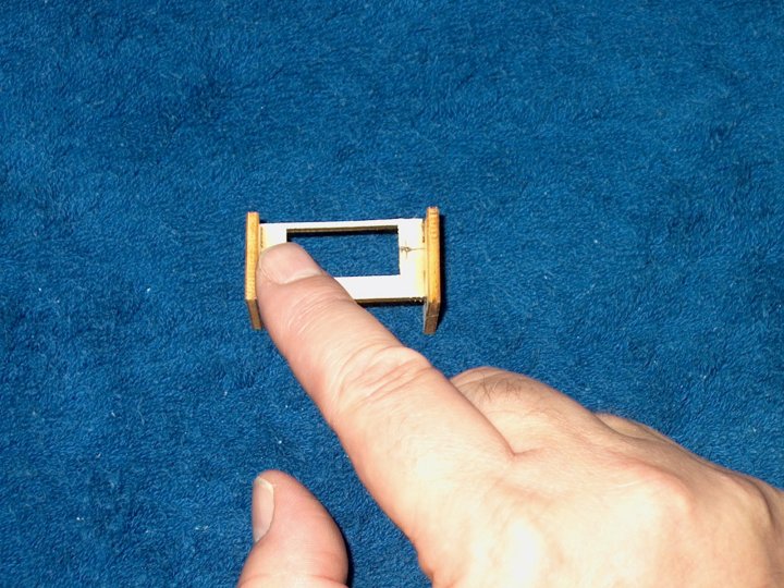
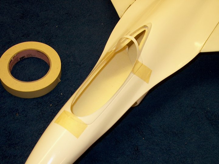
62 - Squeeze the plates in place and
flush | |
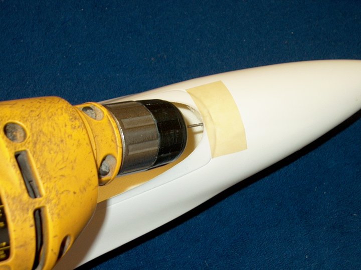
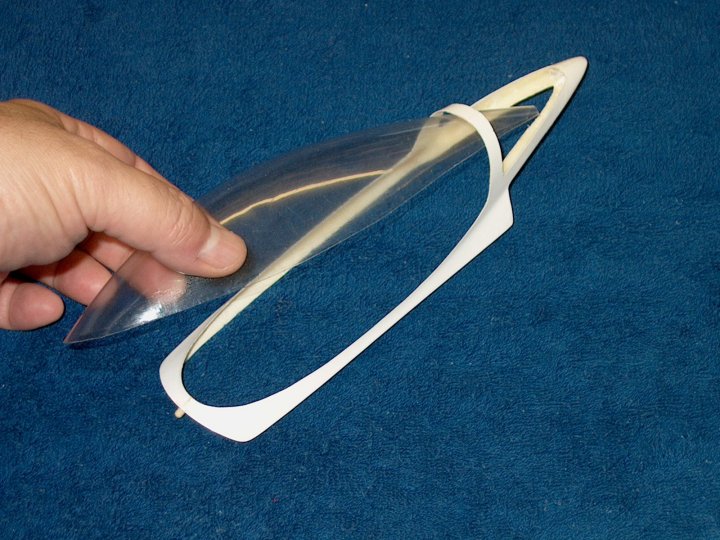
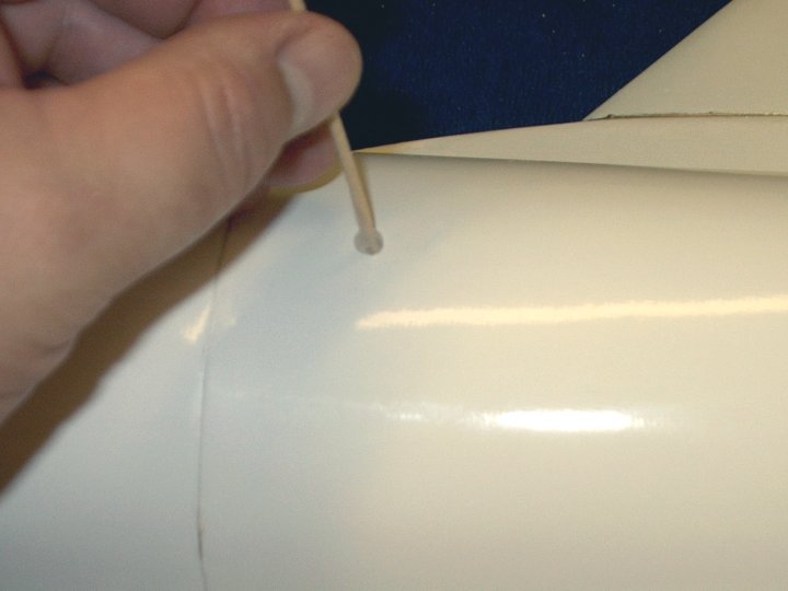
63 - Remove the excess epoxy that could
prevent the servos from sitting flush
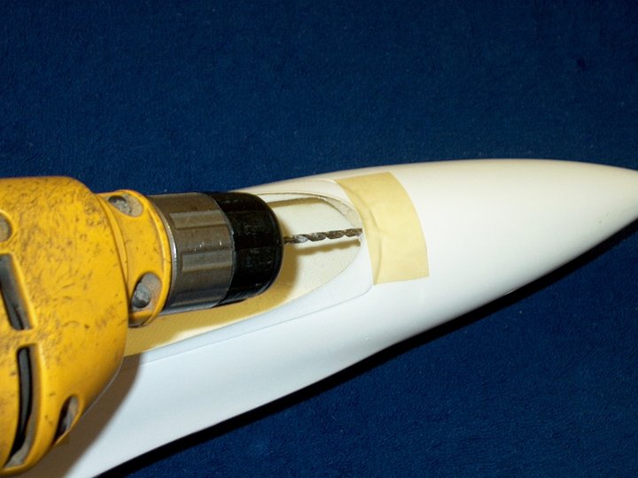
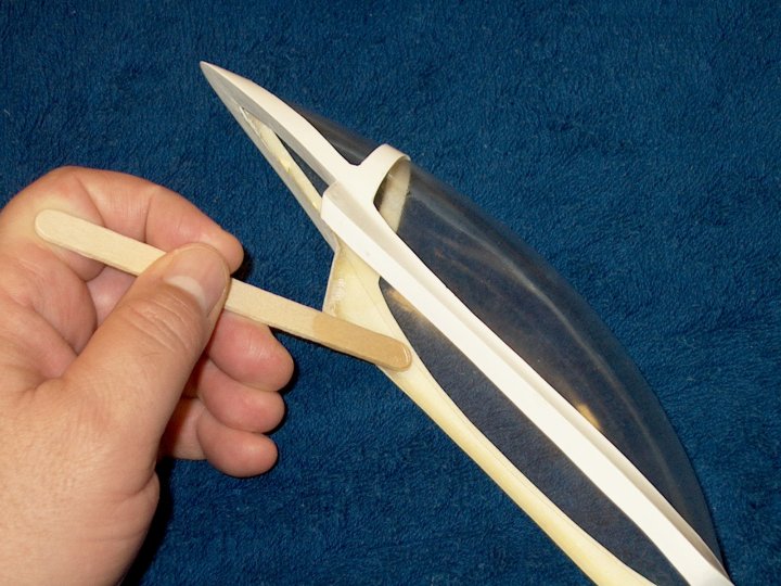
| |
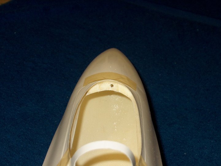
64 - Removing the eopxy leaves a very fine
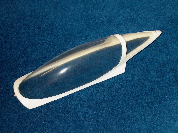
fillet | |
65 - Square up the tray before the epoxy
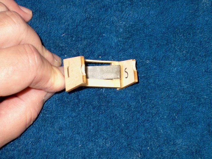
sets | |
66 - Build the other tray and make sure
you make two opposite "mirrored" trays
| |
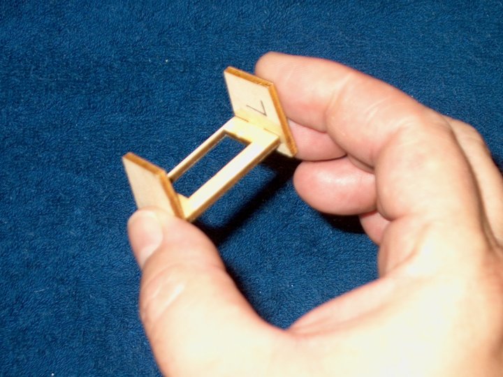
67 - Once both trays are completed, add a
fillet of epoxy to the rear for added strength
| |
68 - Remove the excess epoxy so a nice
fillet is made | |
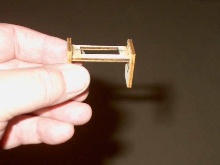
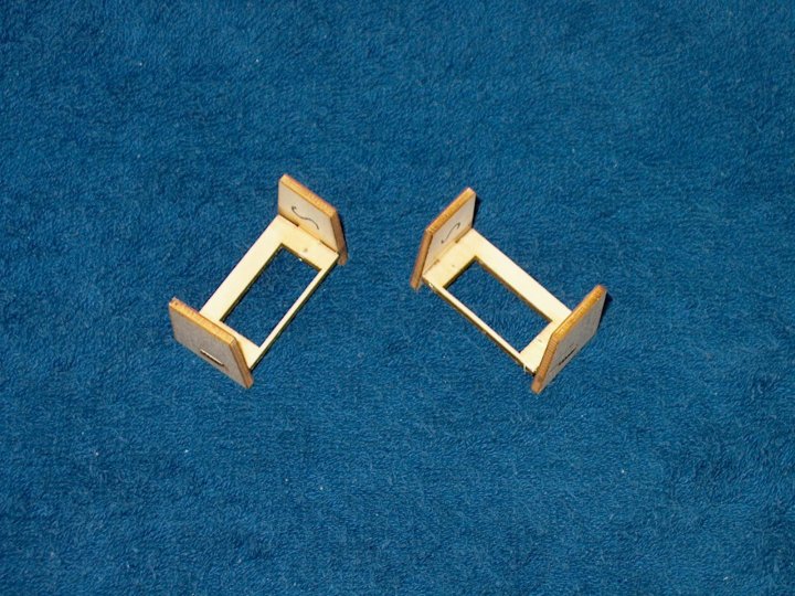
69 - Servo Tray construction completed and
showing fillets at rear side | |
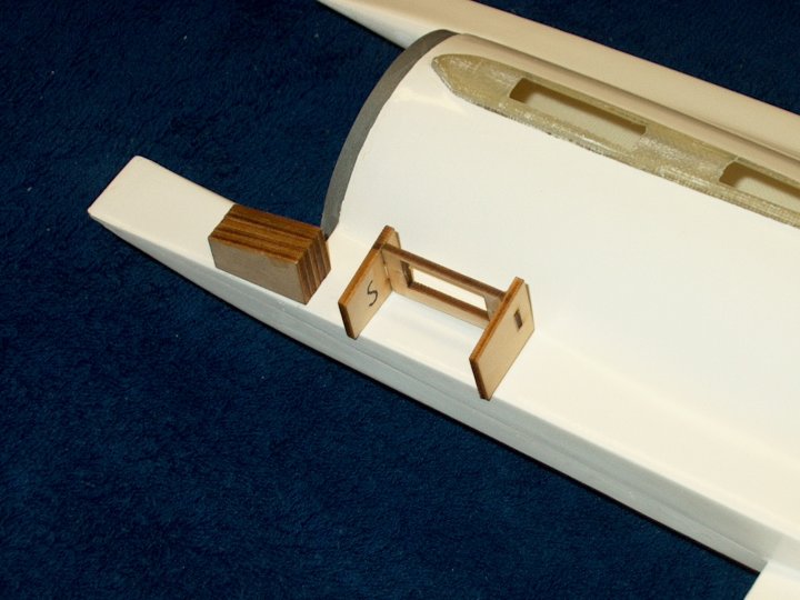
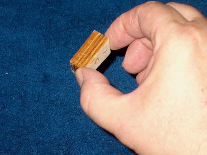
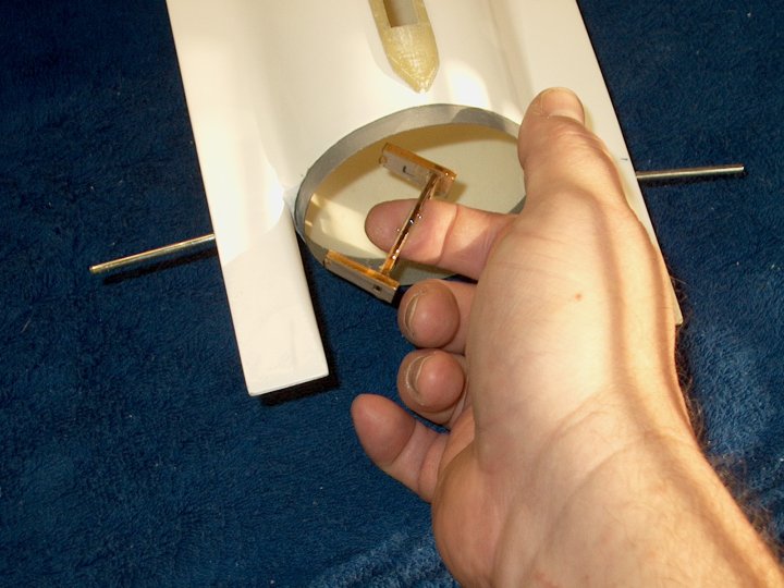
70 - From the top of the fuselage- The
stab block and servo tray are shown near the positions where
they will be installed in the fuselage. Note that the block
tapers rearward and that the tray has the "Shorter" side to
the rear with the thin part of the tray pointing to the top
side of the fuselage | |
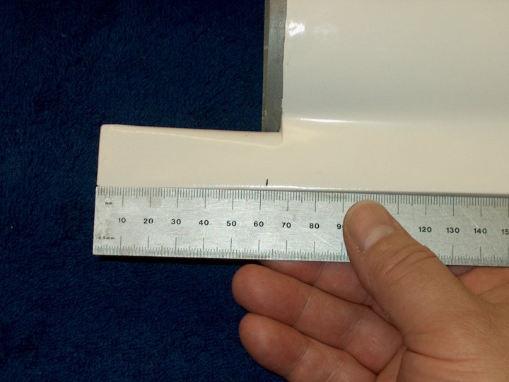
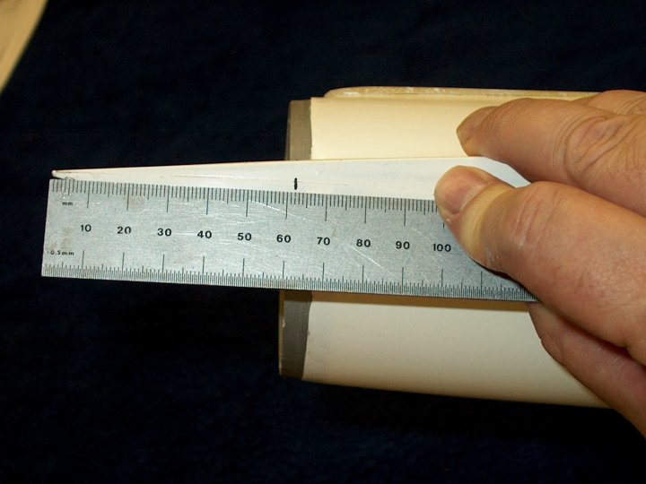
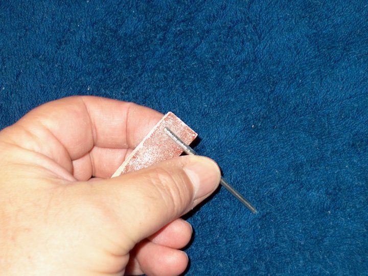
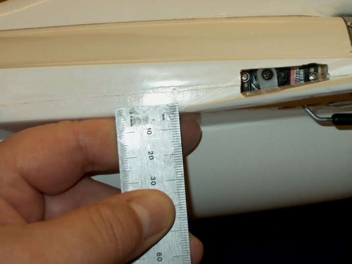
71 - The position for the Horizontal Stab
rods is 62mm from the rear | |
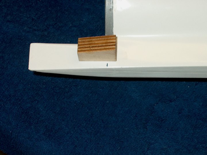
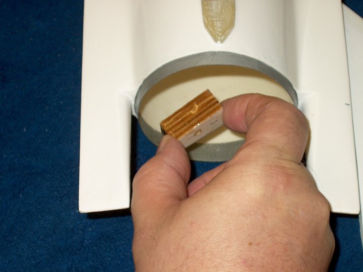
72 - When first installed inside the
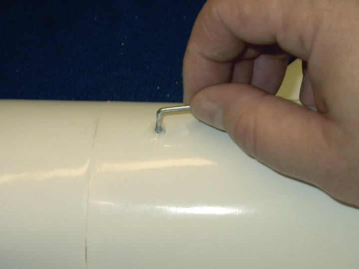
fuselage, the blocks were set too far back and not centered
over the mark | |
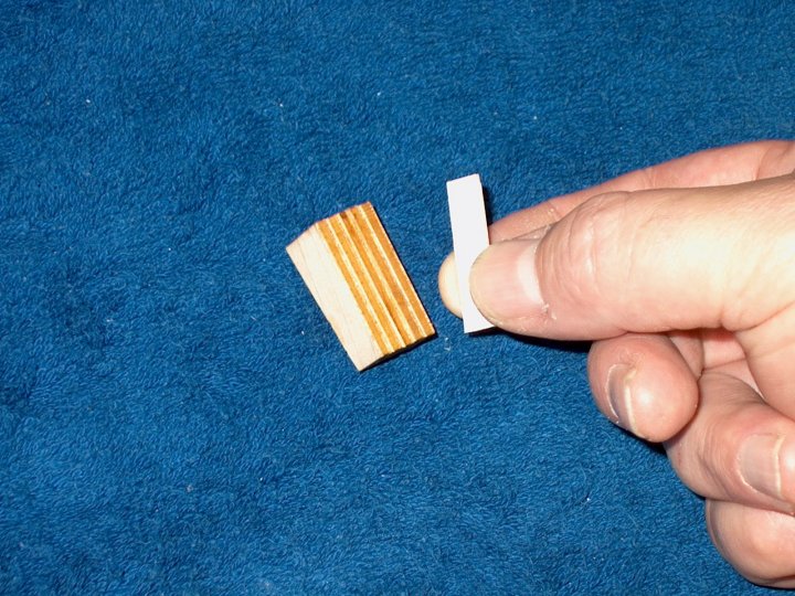
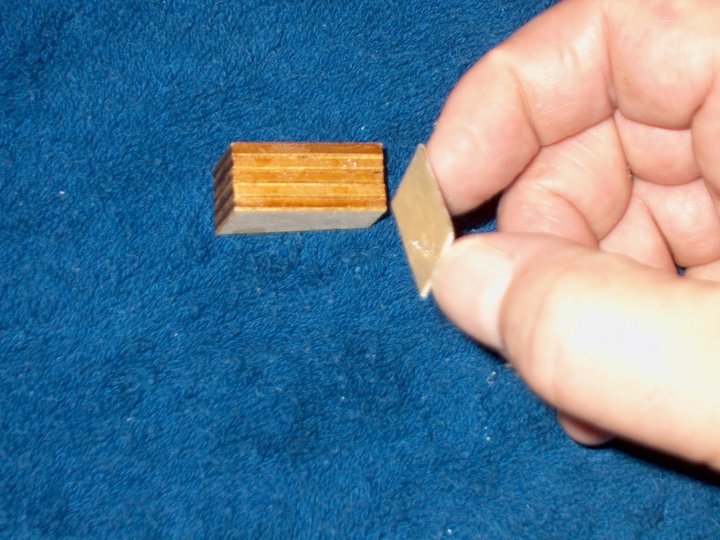
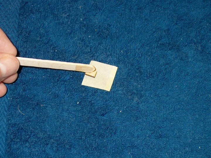
73 - A piece of 1/32" ply was cut as a
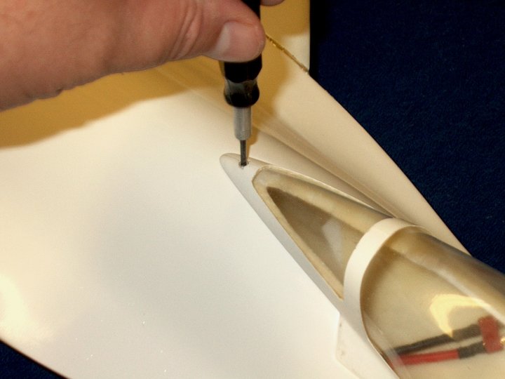
shim to make the block thicker | |
74 - The shim is epoxied to the bottom of
the block | |
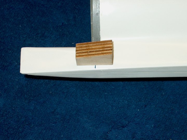
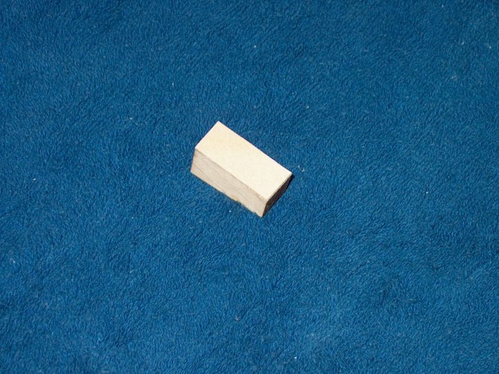
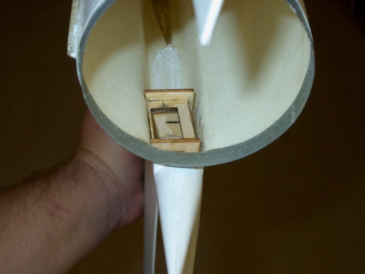
75 - With the addition of the shim, the
block is inserted and the photo shows where it now would sit
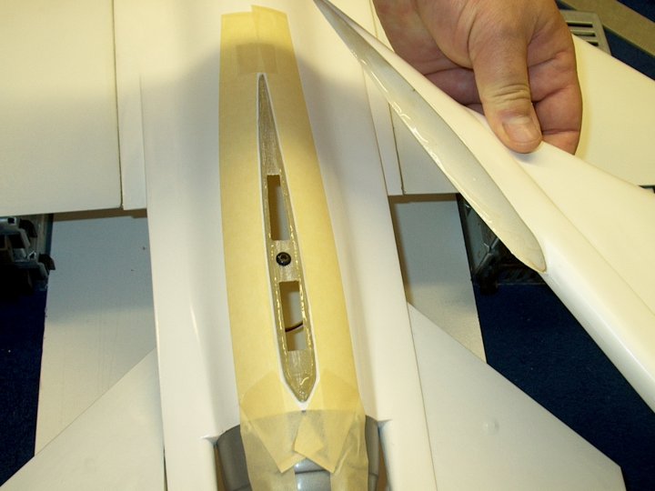
inside the fuselage | |
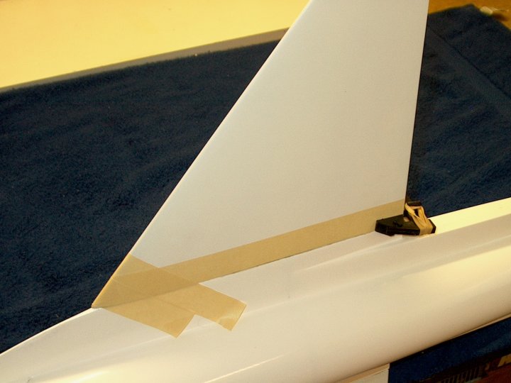
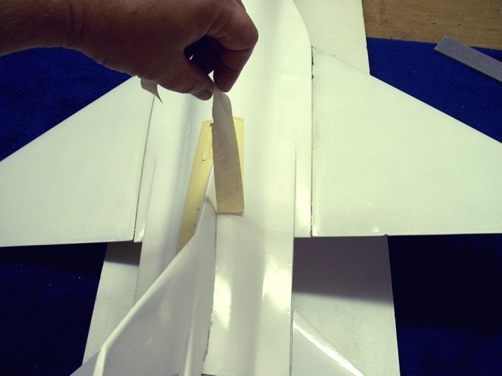
76 - The second block shim is added using
5 minute epoxy | |
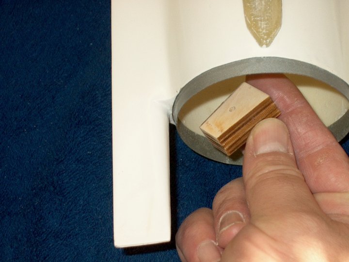
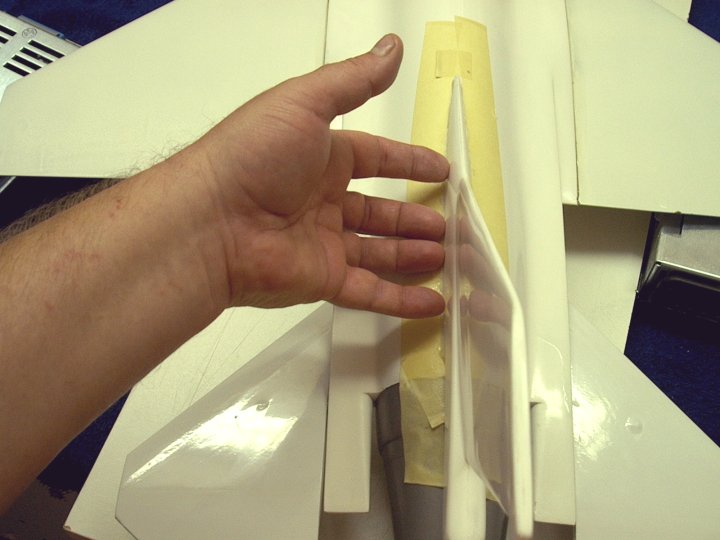
77 - Lightly sand the edges to even out
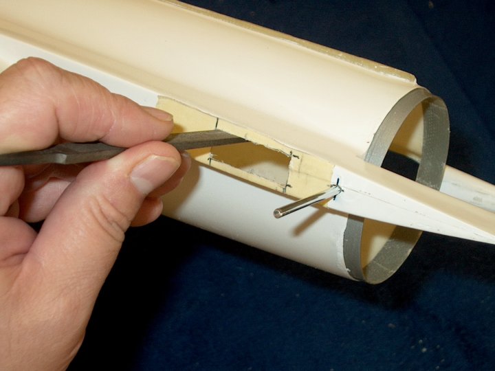
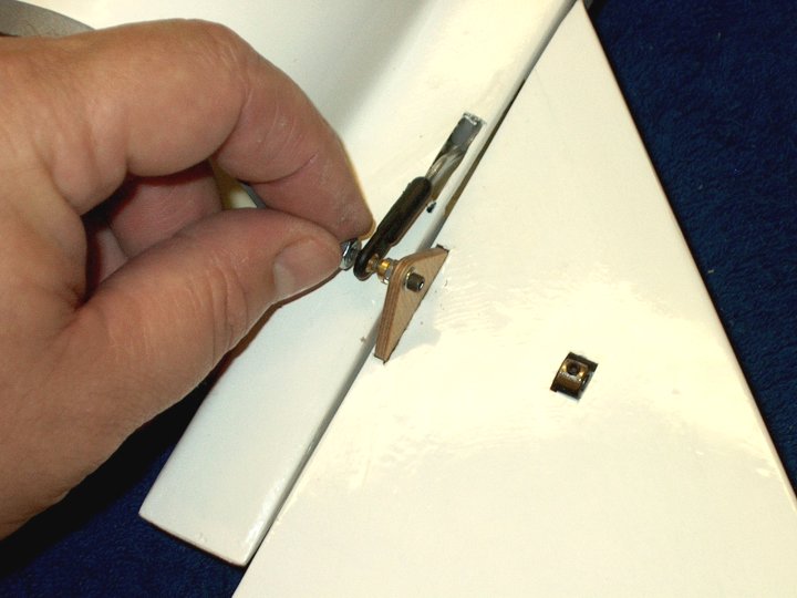
the shim with the block sides | |
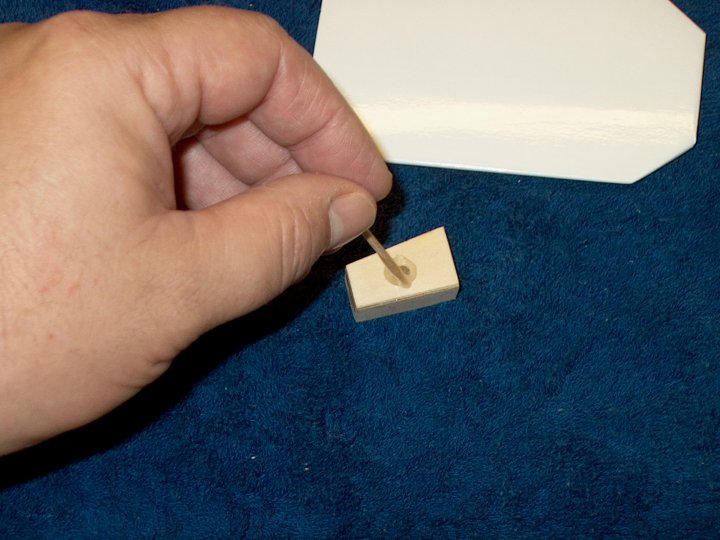
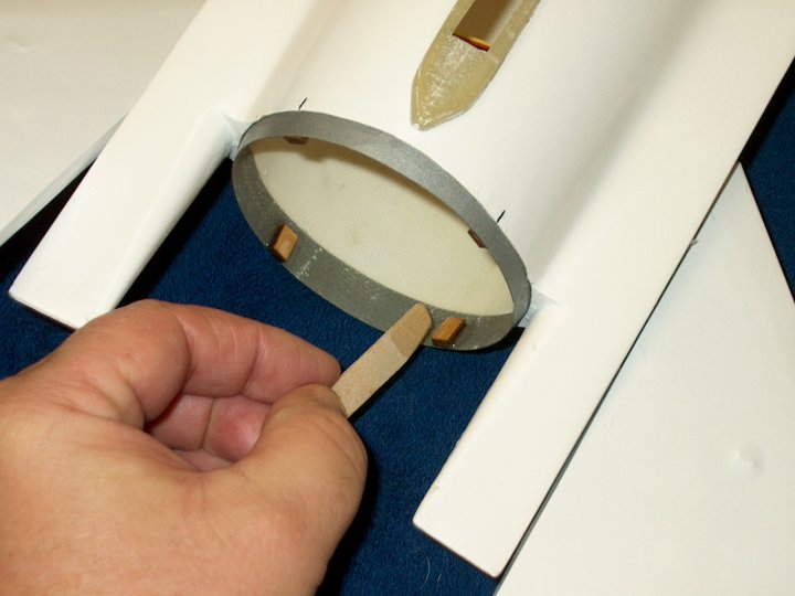
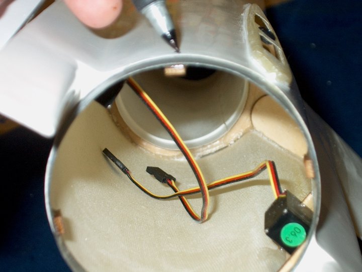
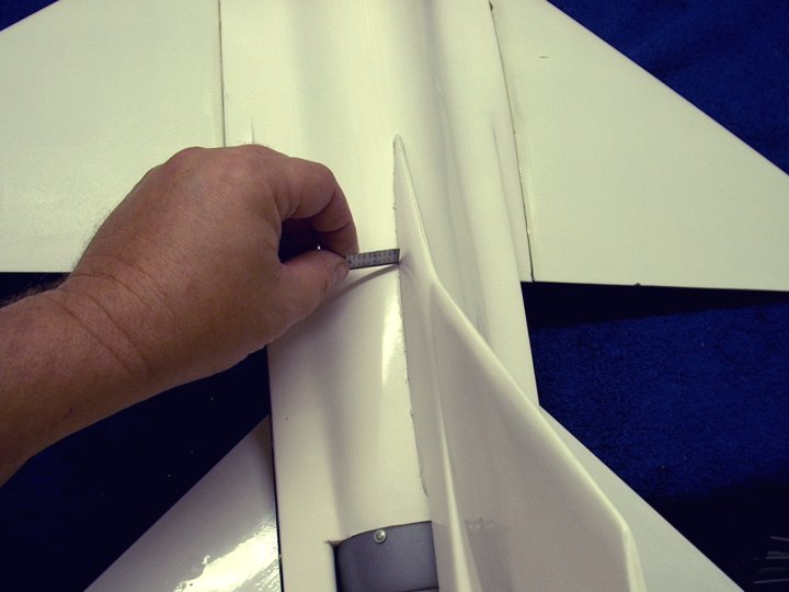
78 - A Warning...the manufacturing process
left some strands of fiberglass that were sharp as needles and
located where the pencil is pointing. If you have these,
carefully break them off inside so you do not get cut
| |
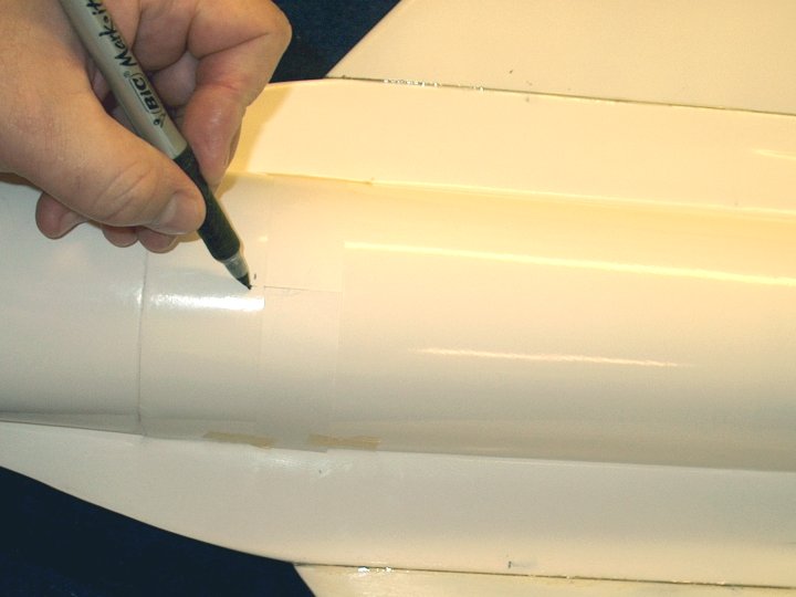
79 - A mark is made on the outside of the
fuselage at 62mm | |
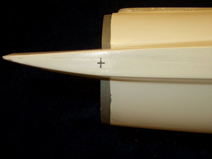
80 - A second horizontal mark is made at
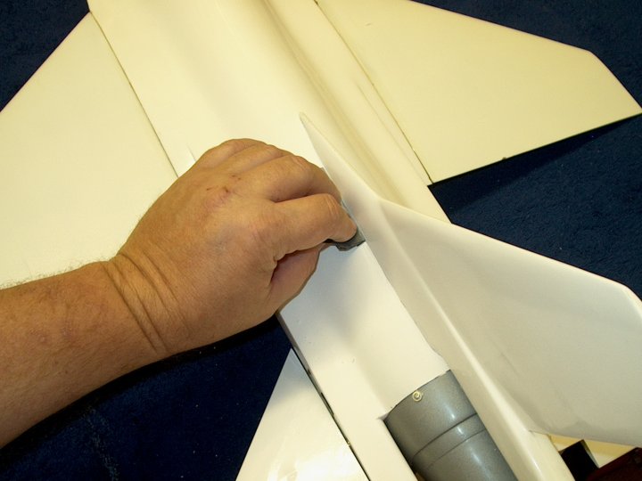
the center of the fuselage | |
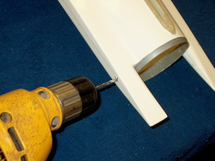
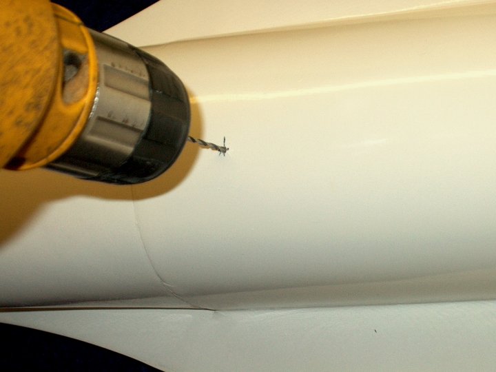
81 - A 1/8" Drill is used to open the
holes at the crosshairs. You may want to use a small bit to
make a starter hole first | |
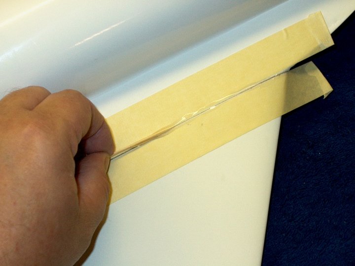
82 - Masking tape is used to wrap around
the block so it can be removed easily later
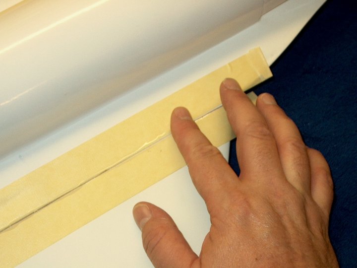
| |
83 - The block is temporarily installed in
the fuselage | |
84 - Keeping the drill square, make a
small mark on the ply inside but do not drill through
| |
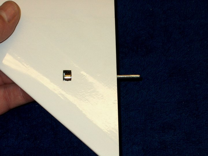
85 - The drill mark is shown centered in
the block | |
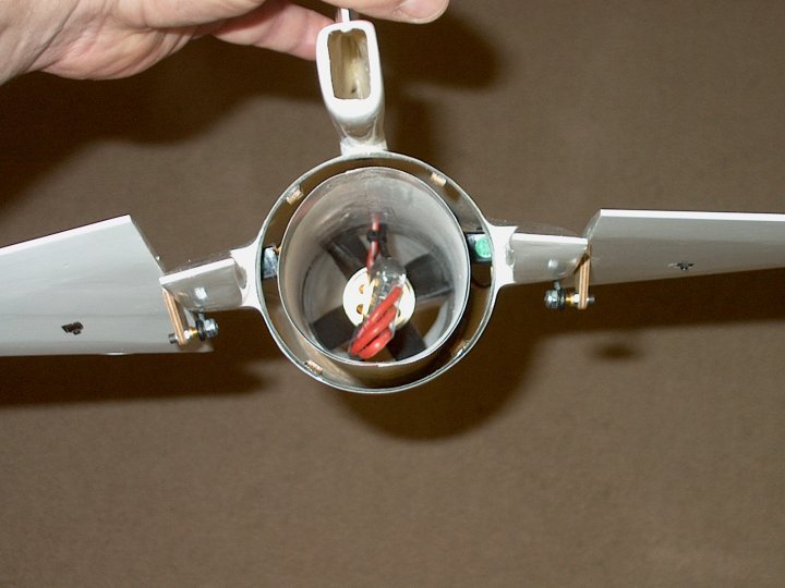
86 - The other block is installed and
marked the same way. Use the masking tape tab to easily remove
the block once it is marked | |
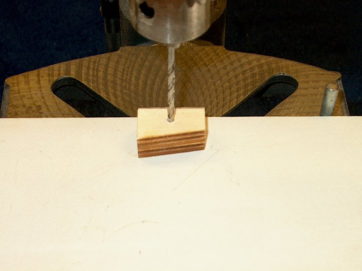
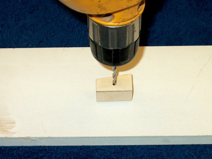
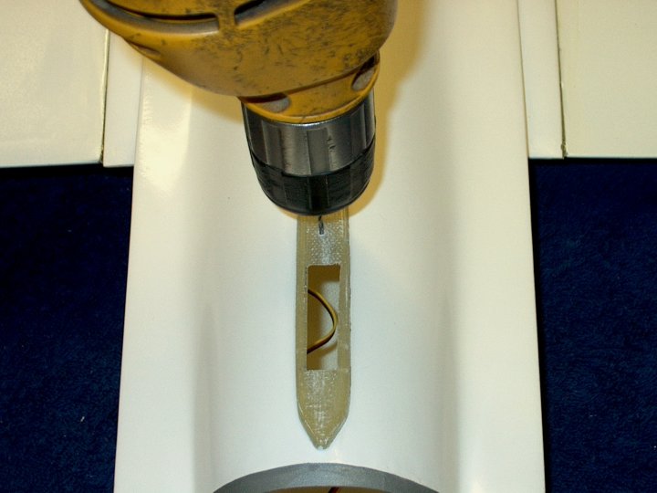
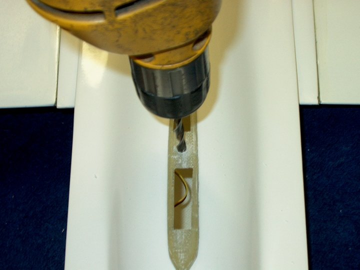
87 - A drill press is used to drill
through the block and keep the hole square
| |
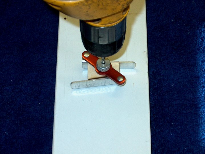
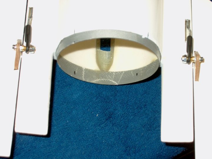
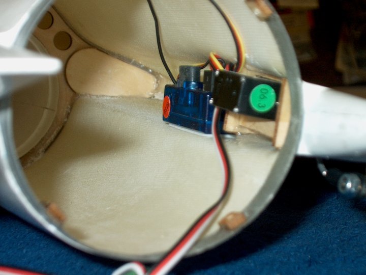
88 - A Hinge drilling jig can also be used
to drill a square hole | |
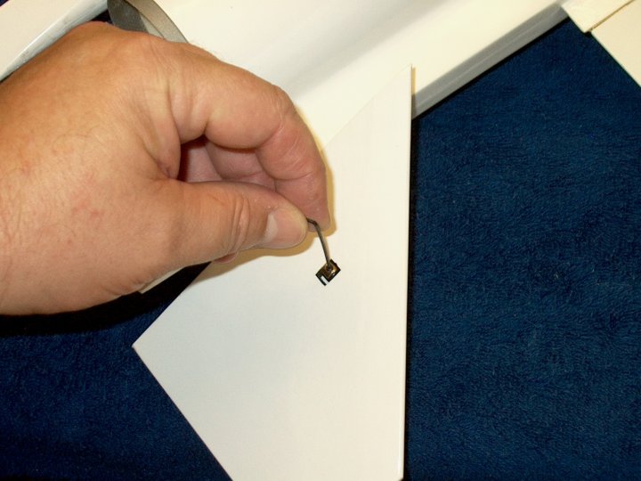
89 - If you do not have a drill press or
hinge jig, the the hole can be carefully drilled by hand. Do a
little at a time making sure the bit stays square both
horizontally and vertically | |
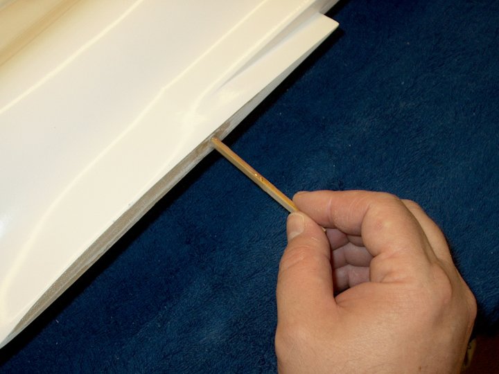
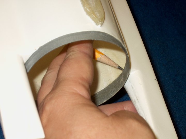
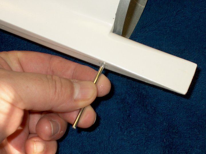
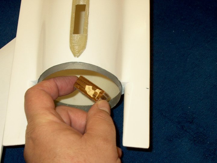
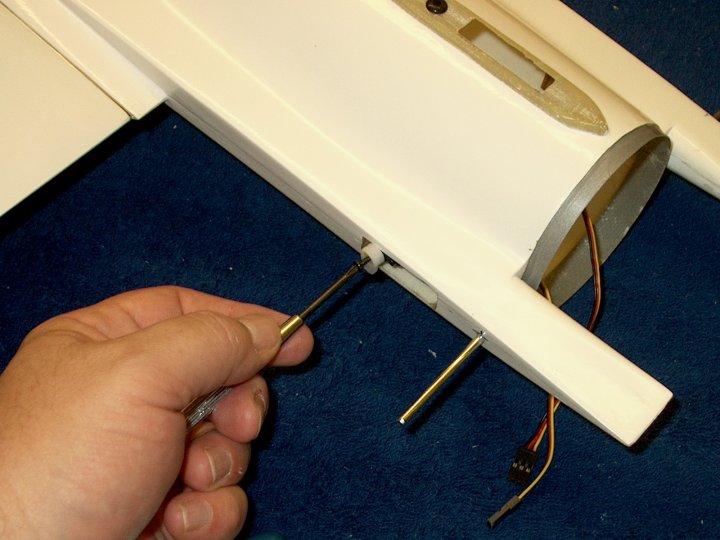
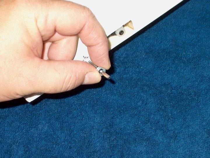
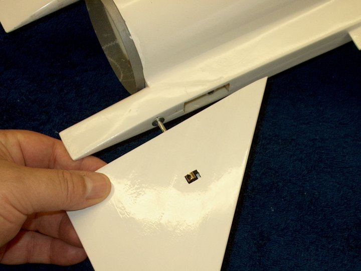
90 - Trial fit the Elevon Rod and use the
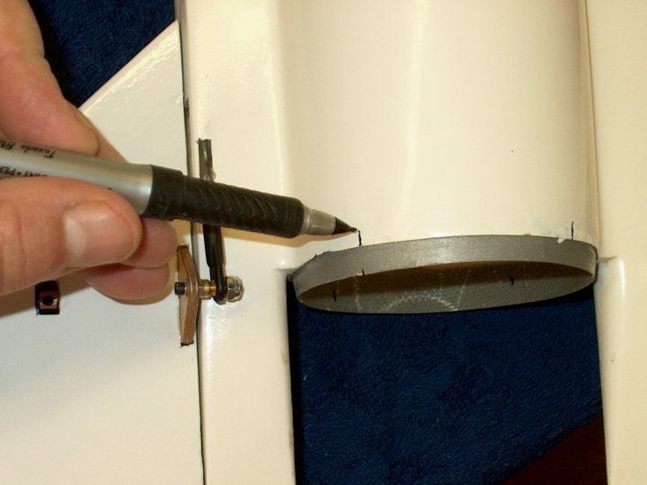
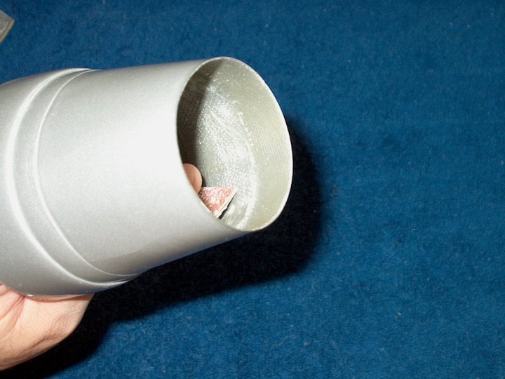
drill to open the hole if necessary so the rod moves in and
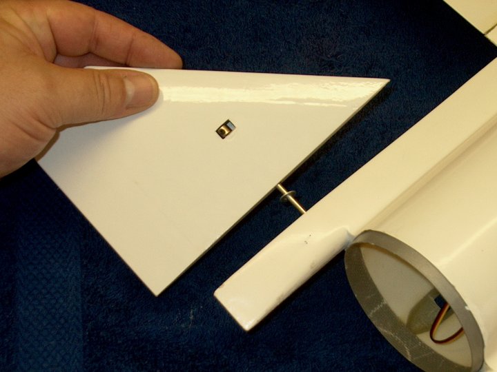
with little effort | |
91 - Install the block in the fuselage
with the angled side toward the top. Do not glue the block in
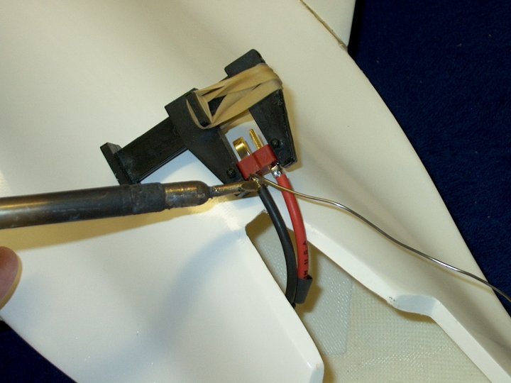
place yet | |
92 - Make sure the hole is aligned and
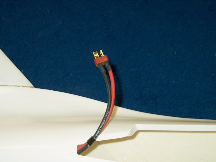
centered on the markers | |
93 - Temorarily install a Elevon rod to
check the angle | |
94 - Rod shown in correct position,
perpendicular to the fuselage where it exits. Note that the
fuselage is molded to include a downward angle on the rod when
compared to the wing...this is normal
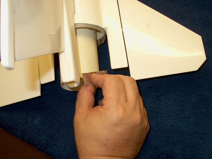
| |
95 - Two 1/8" wheel collars are required
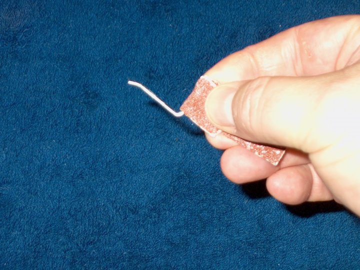
to retain the horizontal stabs. You may have to purchase a set
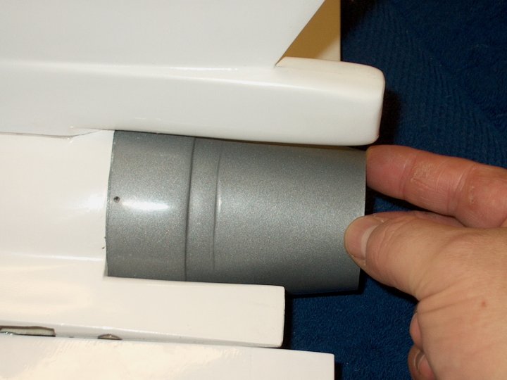
as they were not in the kit | |
96 - Apply some blue Loktite on the
setscrew for the wheel collar | |
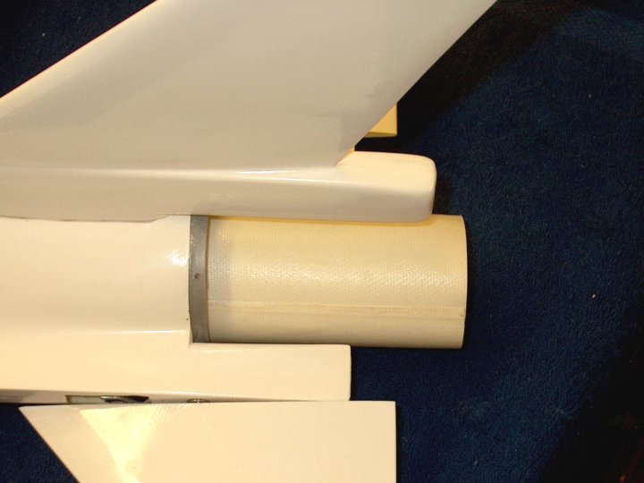
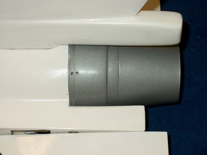
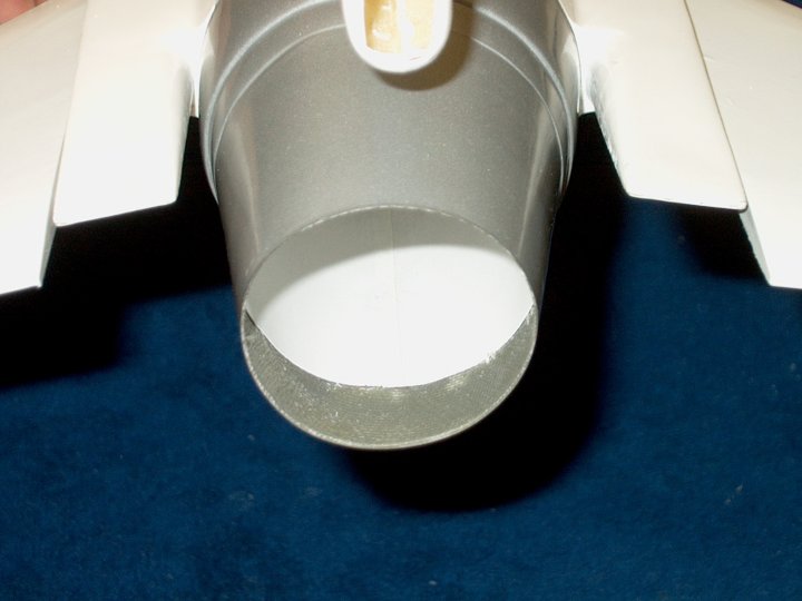
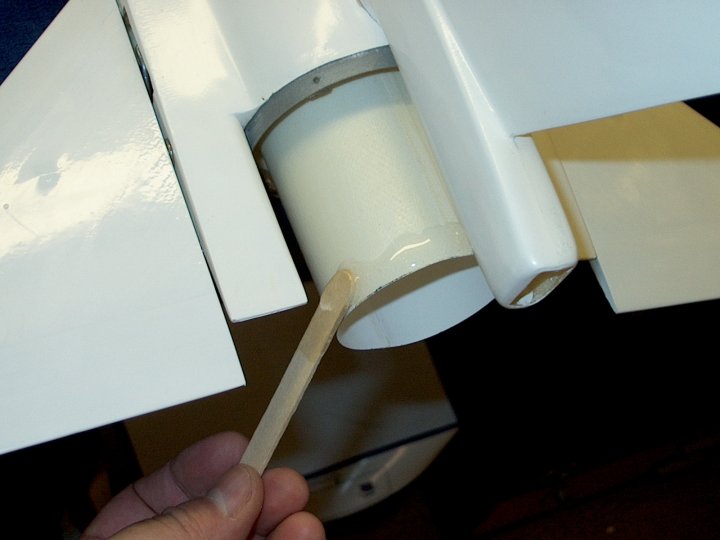
97 - Install the setscrew in the wheel
collar | |
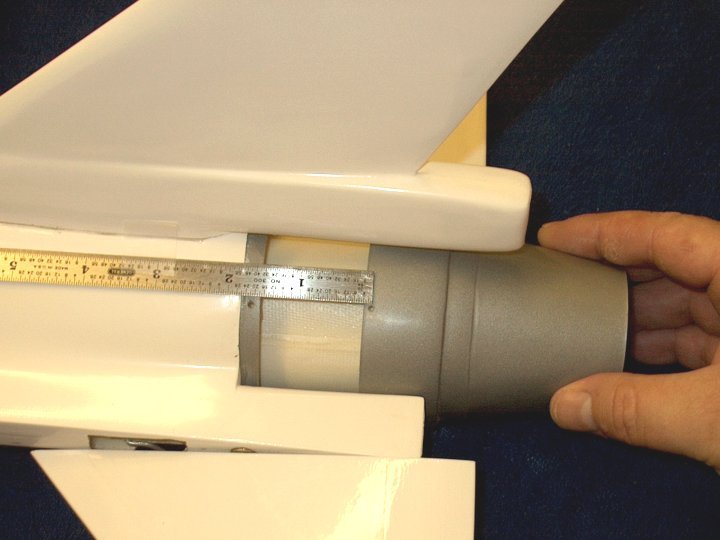
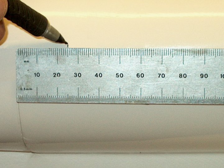
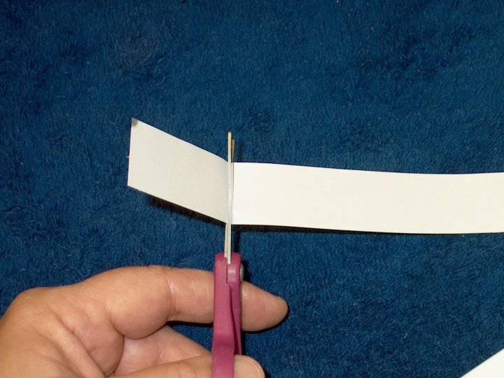
98 - The Horizontal Stabs may need to be
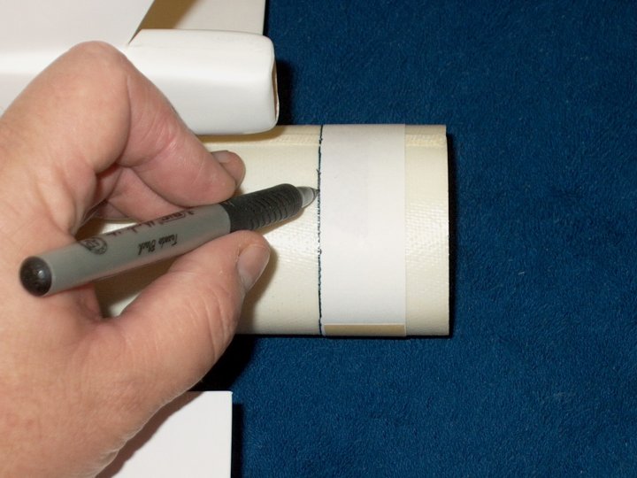
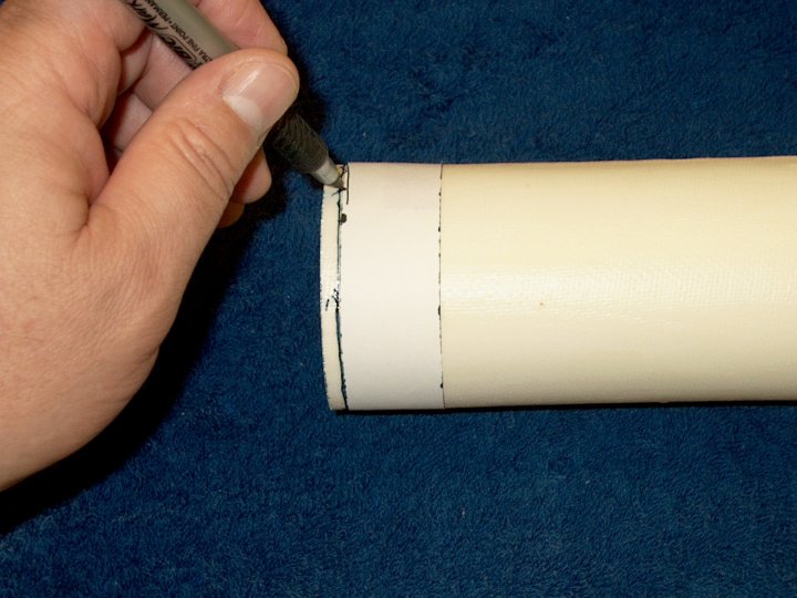
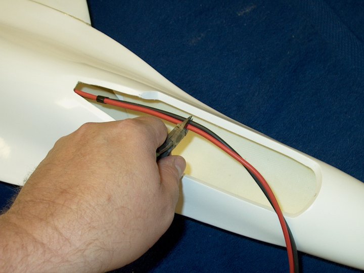
ironed to remove wrinkles | |
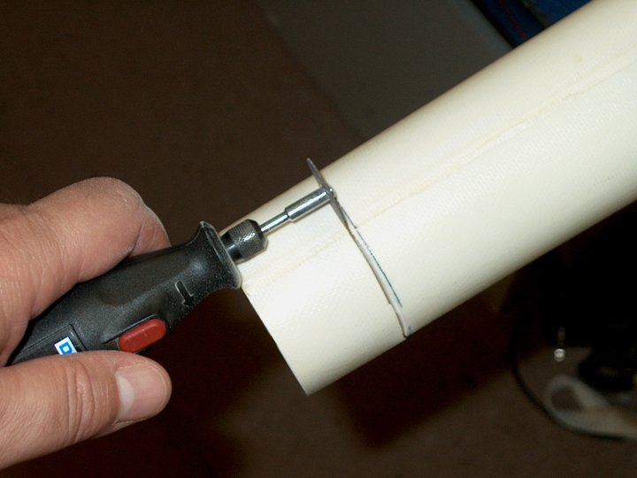
99 - The wheel collar is shown installed
where it is used to mount the stab | |
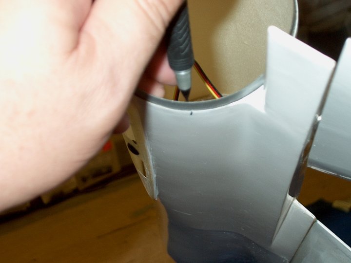
100 - The wheel collar deforms the top of
the monokote | |
101 - the first 1/2" of the Horizontal
Stab rod is roughed up with 60 grit
| |
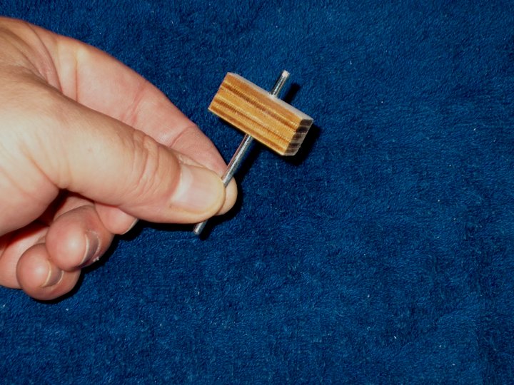
102 - Install the rod in the horizontal
stab and lock it in place with the wheel collar. Make sure
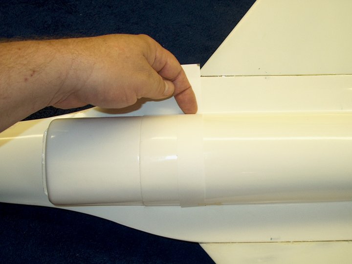
that the rod extends past the collar and butts against the
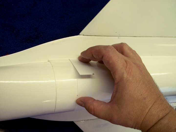
left wall as shown. Also, note that the side of the rod that
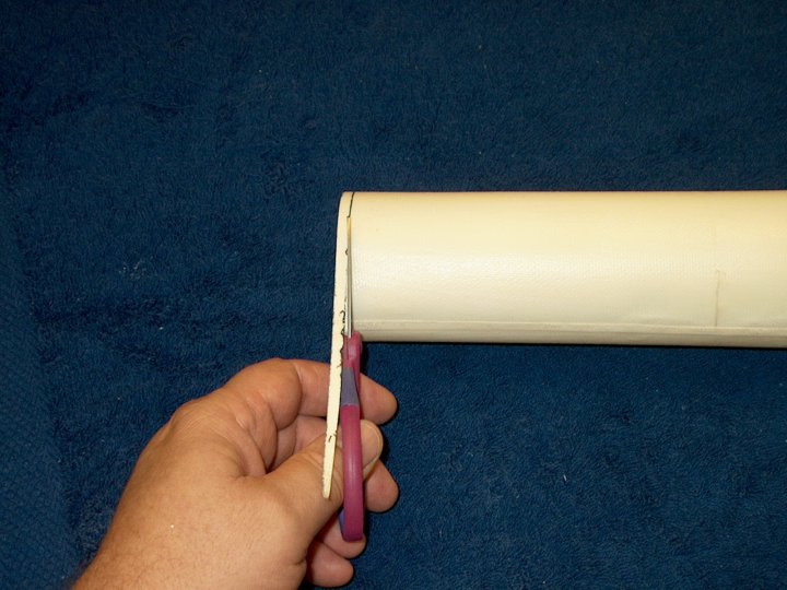
was sanded is shown to the right and will be glued into the
fuselage block | |

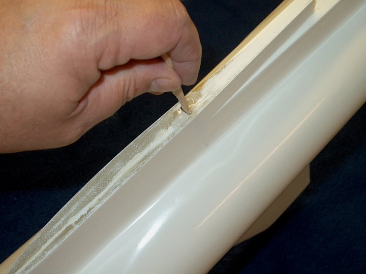
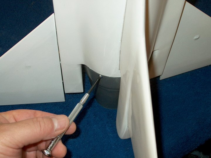
103 - Apply epoxy inside the hole with a
toothpick | |
104 - Apply epoxy to the top and bottom of
the block | |
105 - Install the block in the
fuselage | |
106 - Install the Horizontal stab into the
inner block hole until the root butts against the side of the
fuselage. This will keep the block aligned inside. Put your
finger inside the fuselage and make sure the block is settled
in its location. Hold the stab tight in place with masking
tape | |
107 - Check stab position from the rear to
make sure the angle is aligned with the fuselage trailing
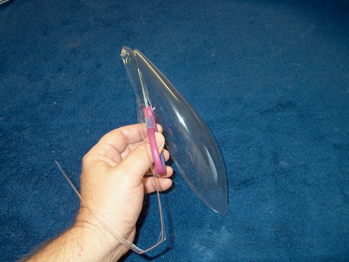
tip | |
108 - Epoxy is applied with a toothpick to
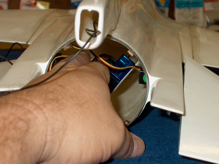
the second block hole | |
109 - Epoxy is applied to the top and
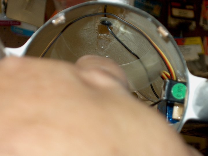
bottom of the block, then it is installed
| |
110 - Horizontal Stab is installed through
the hole and into the block | |
111 - Masking tape is used to hold the
stab flush to the fuselage side. Check your rear angle as you
did with the first stab and make sure it aligns with the
fuselage trailing edge | |

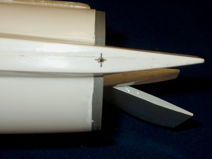
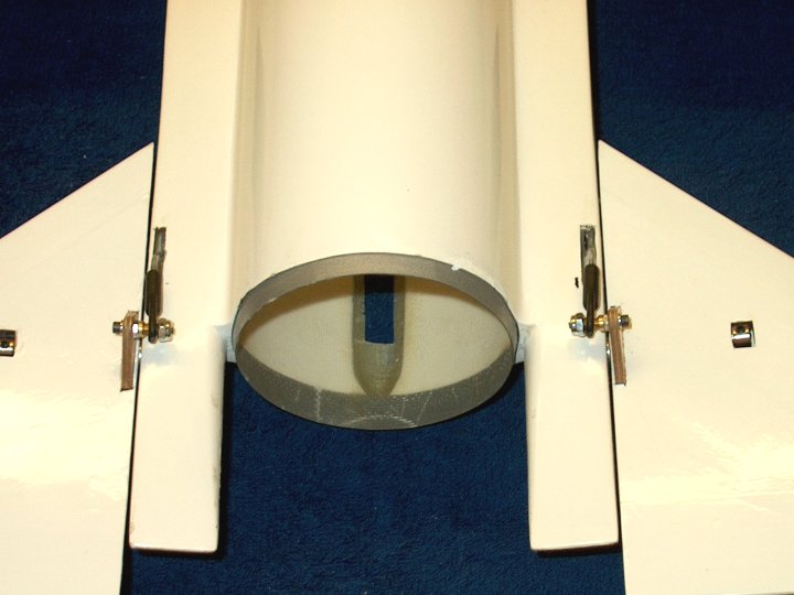
112 - Horizontal Stabs shown installed and
in place | |
113 - The stabs have a slight downward
angle from the rear, which should be even on both sides
| |
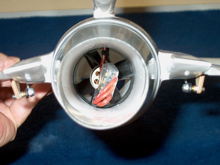
114 - Use a hex wrench to loosen the
retaining wheel collar | |
115 - Remove the stab and wing collar from
the fuselage | |
116 - Horizontal Stab rod installation
completed | |
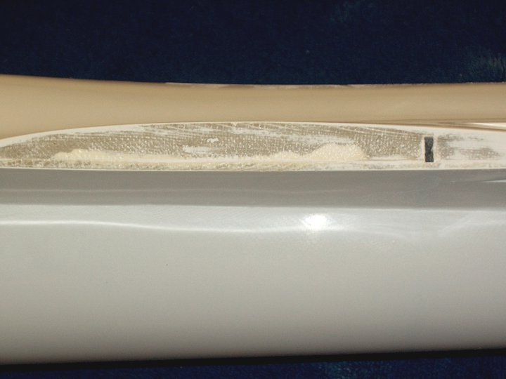
117 - The fuselage halves were assembled
using what appears to be Aeropoxy, as shown by the arrow. This
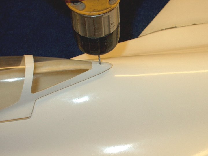
will prevent the servo trays from seating all the way into the
fuselage area. It cannot be easily reached to be sanded
| |
118 - Masking tape is applied to the side
of the fuselage area and marked for servo cutout
| |
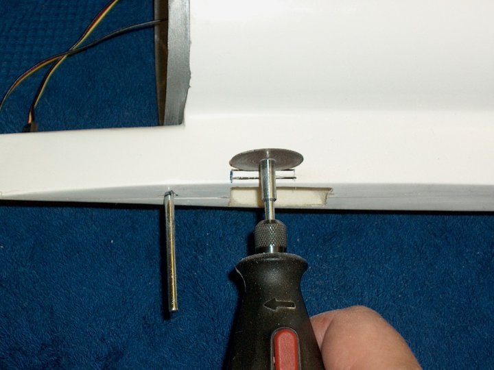
119 - A Dremel with a stone wheel is used
to cut out the opening | |
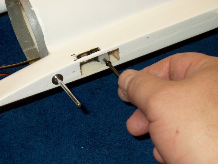
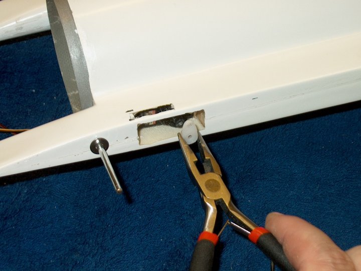
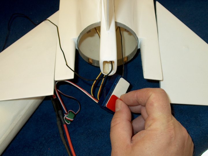
120 - Opening is shown rough cut. It was
very difficult to cut through the Aeropoxy ridge inside. I
used a pair of 90 degree long nosed pliers to break
through | |
121 - The opening is filed until the servo
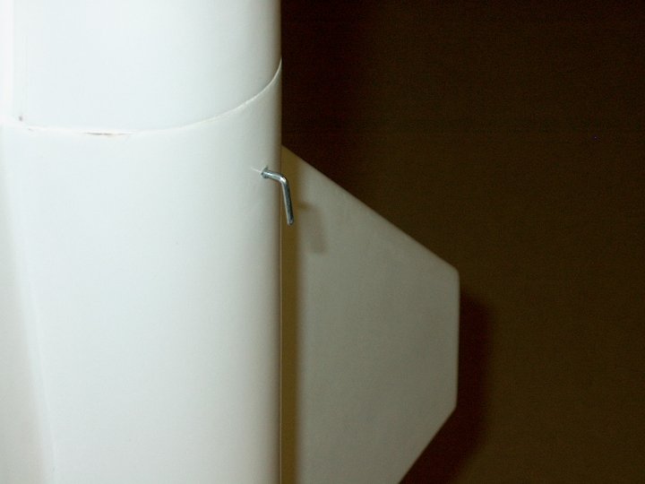
can pass through easily | |
122 - The tape is removed from the
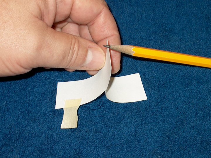
opening | |
123 - The other side is cut with a dremel
and corners are cut with a hobby knife
| |
124 - The opening is filed until the servo
can pass through easily | |
125 - A notch is cut in the area where the
Aeropoxy seam hits so the tray will sit flush with the outer
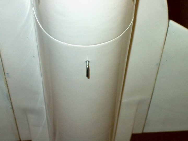
wall | |
126 - A slight bevel was added to the tray
for easier insertion of the servo | |
127 - Epoxy is applied to all edges of the
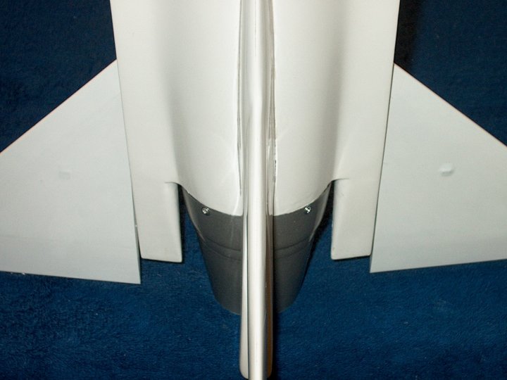
tray, both top and bottom | |
128 - The tray is inserted into the
fuselage and placed in position | |
129 - The tray is shown set in place; make
sure it is centered over the cutout you made for the servo.
Add fillets of epoxy as necessary | |
130 - The second tray is prepared for
installation | |
131 - The second tray is installed
| |
132 - Trial fit a servo into the
tray | |
133 - Servo set in place...do not screw in
place yet | |
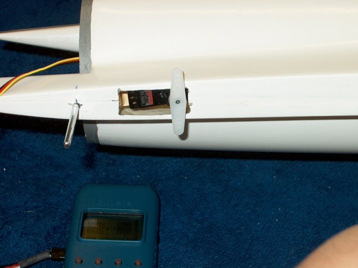
134 - Push the servo out of its tray from
inside and using your radio or a servo tester, center the
servo, then temporarily install the horn
| |
135 - Install horn so it is perpendicular
to the fuselage | |
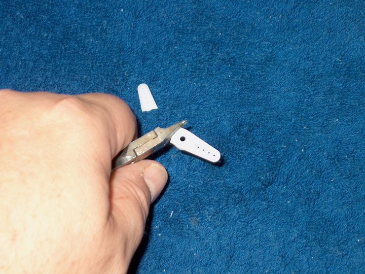
136 - Remove the upper portion of the horn
and sand to round it out | |
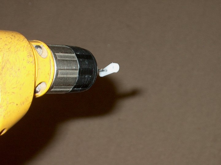
137 - A 1/16" drill bit is used to drill
the hole that is closest to center | |
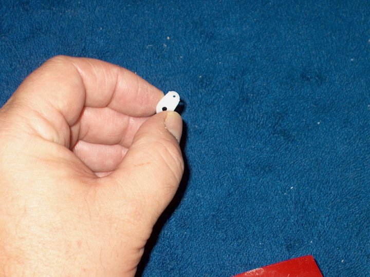
138 - The horn is cut at the second hole
and rounded as shown | |
139 - Install the sevo horn pointed down
and centered, then use the servo horn retaining screw to
premanently fasten the horn | |
140 - Perform the same steps to the other
servo horn, cutting to length and shaping. Install the horn
pointing downward | |
141 - Install the servo horn retaining
screw | |
142 - The servo is mounted in position
using the supplied mounting screws | |
143 - Slide one of the two washers in the
kit over the Stab shaft. This will act like a bearing for the
stab and prevent rubbing on the sides of the fuselage
| |
144 - Install the stab and retaining wheel
collar | |
145 - Holding the stab tight against the
fuselage, tighten the wheel collar | |
146 - Install the other washer, stab and
wheel collar, then tighten | |
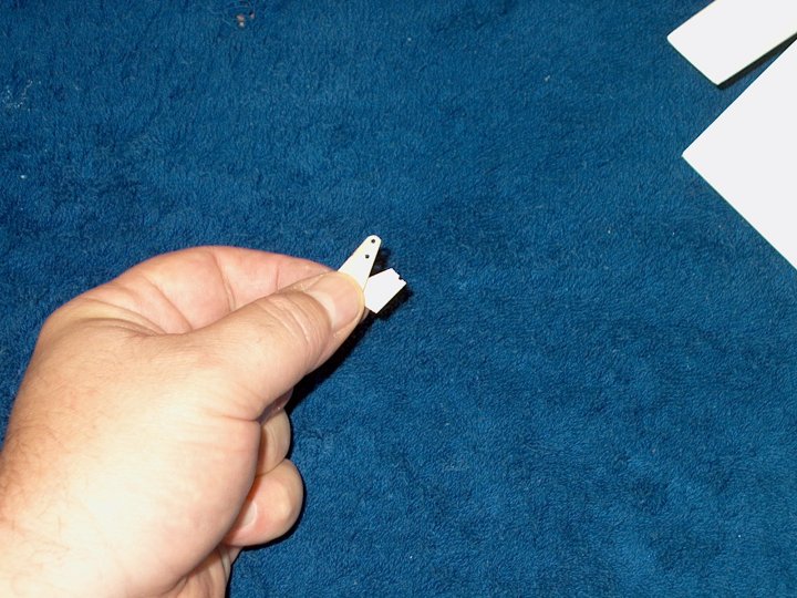
147 - The ply stab horns that come with
the kit are cut wrong, very flimsy and could be dangerous if
installed. Do not use these plywood horns
| |
148 - New horns are cut from 1/8" aircraft
plywood | |
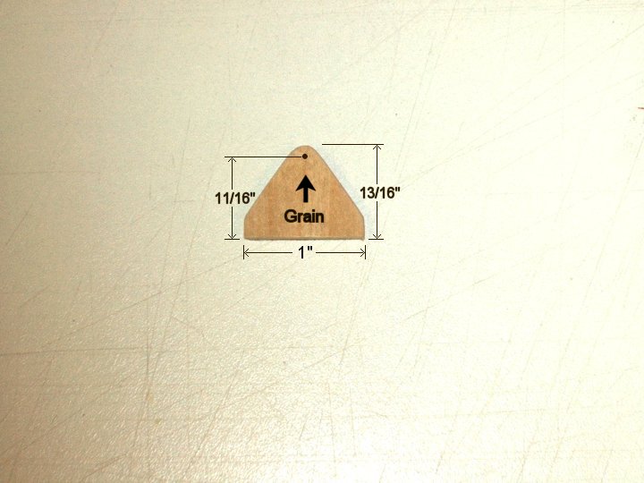
149 - Dimensions and shape of the new
stronger control horn. If you wish to buy them instead, you
can use nylon control horns. Make sure you cut it in the
proper grain direction | |
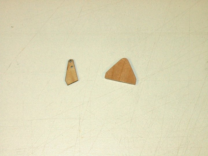
150 - Shape of old control horn compared
to the new one | |
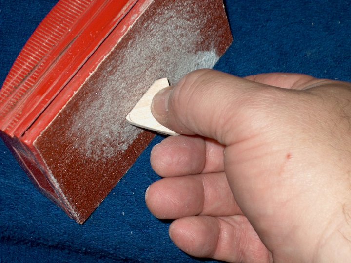
151 - Strengthen the horn by coating it
with thin CA. Do not coat the bottom 3/16" as it will be
epoxied in place | |
152 - Horns are stacked on top of
eachother. A hole is drilled for the pushrod, then a 1/8" hole
is drilled at the bottom center to clear the stab pivot
rod | |
153 - Matched horns are now ready for
final fitting | |
154 - The horn slot is positioned over the
stab rod hole, then the sides are marked to cut to correct
length | |
155 - A slot is cut vertically 1/8" wide
and 1/32" from end, just inside the spar cap as shown
| |
156 - A small flat screwdriver is used to
clean out the slot | |
157 - Slot ready for horn install
| |
158 - Horn is epoxied in place. Make sure
it stays vertical and does not lean
| |
159 - Epoxy is applied and the second
control horn is installed | |
160 - Excess epoxy cleaned up with
denatured alcohol and horn installation is shown
completed | |
161 - A 12" long piece of 2-56 single end
threaded pushrod is cut to about 4" in length
| |
162 - A drill is used to ease the
installation of the rod in the Ball Clevis
| |
163 - The rod is temporarily installed and
a mark is made on the inside for the slot
| |
164 - A mark is made on the outside for
the slot | |
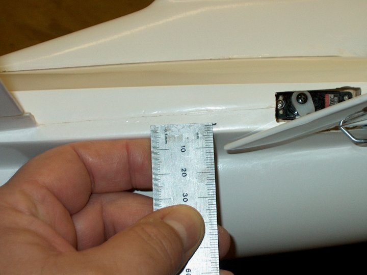
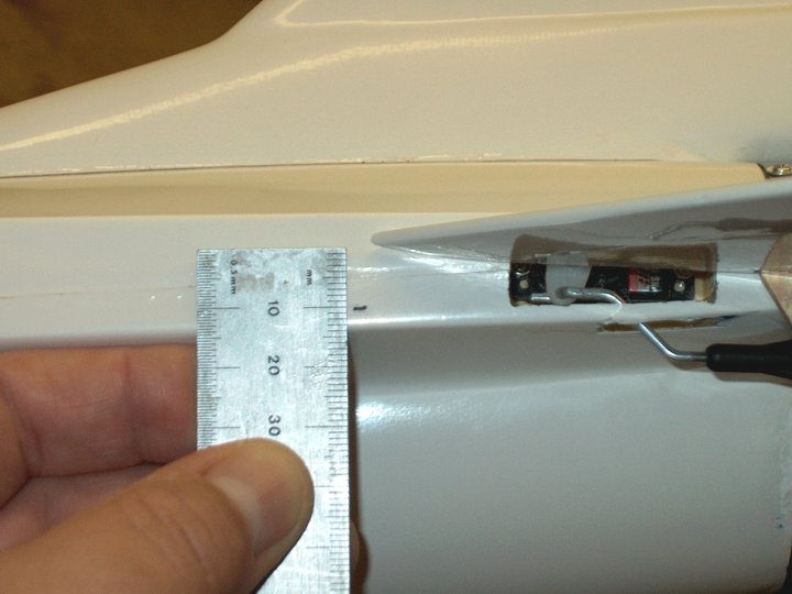
165 - A mark is made on the fuselage 3.5mm
from the bottom front | |
166 - The poshrod is bent as as
shown...make sure you make two opposite pushrods of the same
shape and bend | |
167 - A longer 3/4" bolt had to be used,
so it was cut flush to the nut | |
168 - The rod slot is cut out at the marks
you made. The back part of the slot (the left side) is flush
to the servo tray inner wall and the slot is 7/8" in
length | |
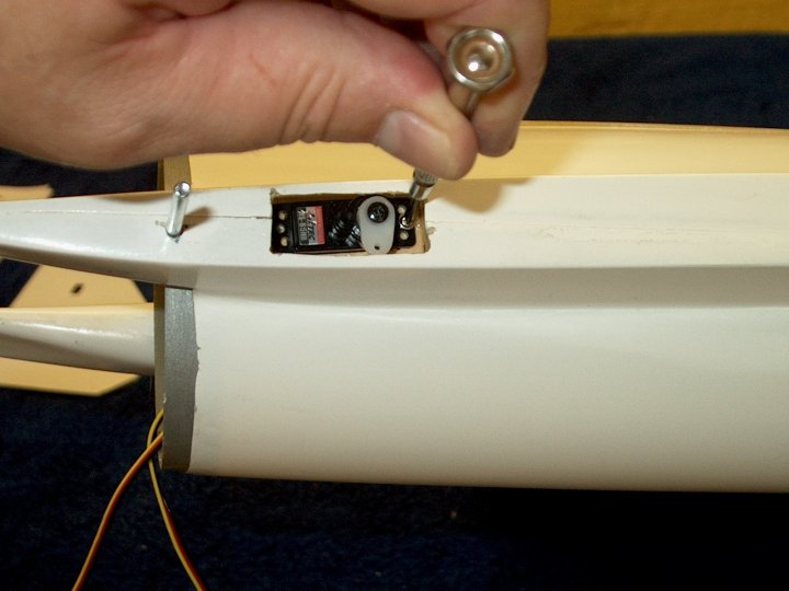
169 - The servo arm screw is
removed | |
170 - Next, the servo arm is
removed | |
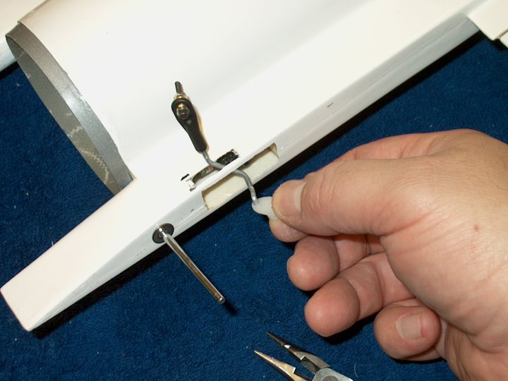
171 - The pushrod is fed through the slot
and the servo arm is installed on the Z-Bend
| |
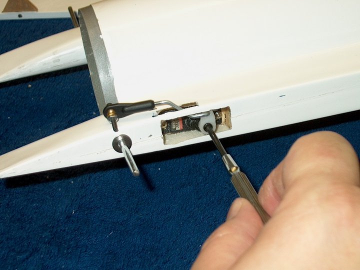
172 - The servo arm and screw are
re-installed. Make sure the arm is placed back in the same
position | |
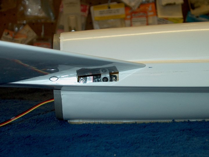
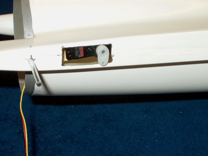
173 - Servo at center and fin 3.5mm from
bottom mark is shown to the right | |
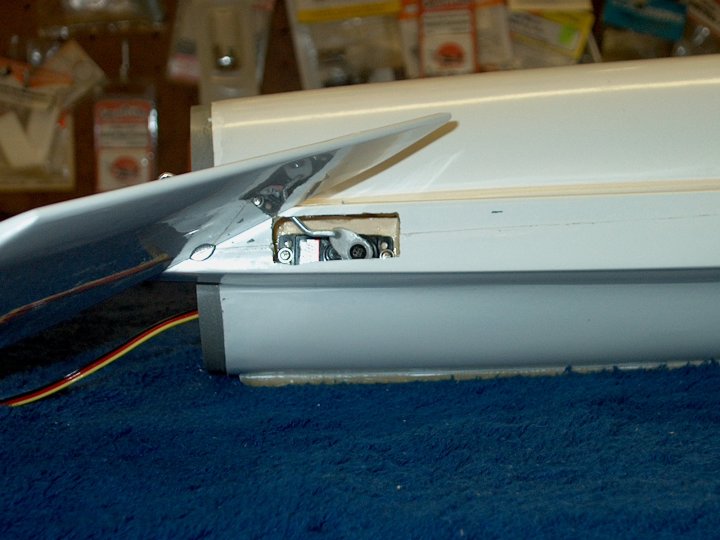
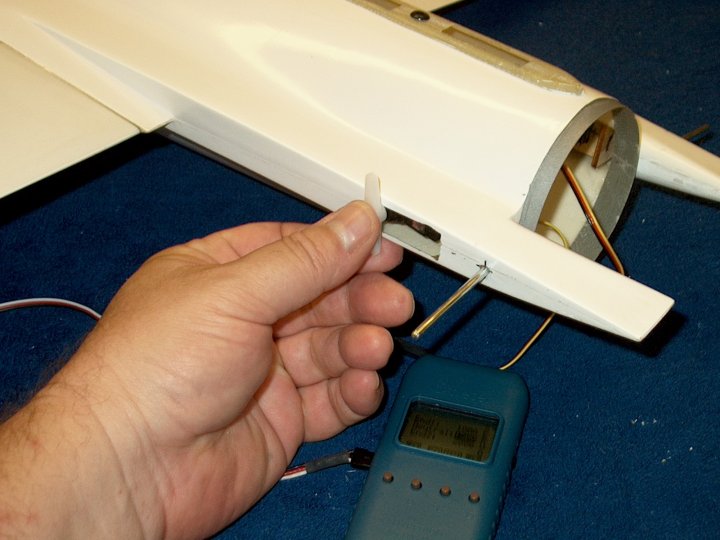
174 - Full up travel on servo
| |
175 - Full down on servo...pleanty of
travel | |
176 - The slot for the servo pushrod is
cut out on the other side of the fuselage
| |
177 - A hobby knife is used to cut the
short ends | |
178 - Once again, the servo arm is
removed, the pushrod is fed through the slot and the servo arm
is installed at the Z-Bend | |
179 - Elevon is installed and tightened in
place | |
180 - Final installation of control
arm...the bolt with flat washer is threaded into the control
horn | |
181 - A 2-56 nut is installed to lock the
bolt in place | |
182 - The supplied brass bushing spacer
that comes with the ball clevis is installed
| |
183 - The ball clevis is installed on the
bolt | |
184 - The clevis is retained using a
nylock nut. Note that final assembly shows the nylock nut on
the inside, which allows for easy removal and adjustment of
the clevis | |
185 - Nut is tightened
| |
186 - Pushrod installation on one side
shown completed | |
187 - Bolt is installed in second Elevon
control horn | |
188 - Washer, brass spacer, ball clevis
and nylock nut are installed | |
189 - Pushrod installation
completed | |
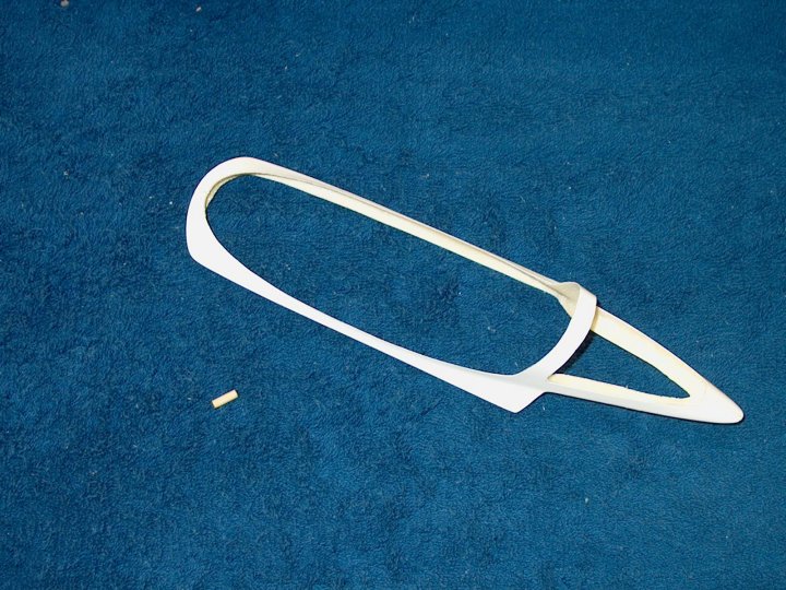
190 - The Canopy and supplied wooden dowel
are ready to install | |
191 - Tape the canopy in place so it is
even front and back | |
192 - A 1/16" pilot hole is drilled in the
front center | |
193 - The hole is opened up with a 1/8"
drill. It should be centered in the front
| |
194 - Photo shows hole drilled
| |
195 - The wood dowel is rounded at the tip
using 100 grit sandpaper. This will ease installation when in
use | |
196 - Pic shows rounded tip
| |
197 - The dowel is installed in the canopy
frame with rounded end forward | |
198 - Pic shows position of dowel
| |
199 - Epoxy is applied to glue the dowel
in place | |
200 - While the epoxy is still wet,
install the canopy and keep it centered while the glue
sets | |
201 - Tape is used to hold the canopy in
place | |
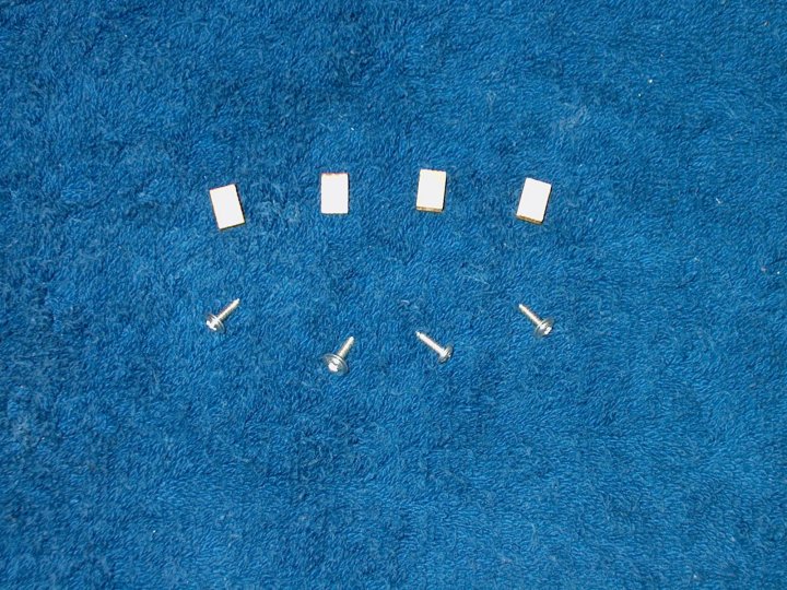
202 - Tailcone Installation: Shown are the
tailcone ply retention plates and screws
| |
203 - Marks are made on the fuselage for
plate location | |
204 - Marks are made inside for the
location of the ply plates | |
205 - Marks are shown...rough up the
inside areas with 60 grit sandpaper
| |
206 - Plywood Plate is installed on a
piece of masking tape and epoxy is applied to the facing
side | |
207 - Plate is positioned over the mark
and held in place with the tape until the glue sets. This is
repeated for all four plates | |
208 - All plates installed and glue is
left to set | |
209 - All plates installed and glue is
left to set | |
210 - All four plates are shown
installed | |
211 - Marks are made again on outside of
fuselage dead center of each plate | |
212 - The tailcone is installed. Place the
best looking side up | |
213 - Masking tape is used to hold the
tailcone in place | |
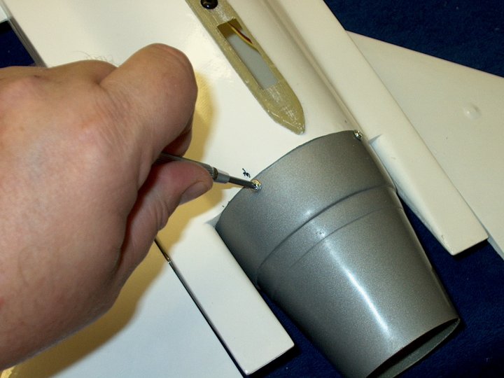
214 - Holes are drilled, first with a
1/16" bit, then a 3/32" bit | |
215 - A mark is made inside the tailcone
and fuselage to be used as alignment marks when re-installing
the tailcone | |
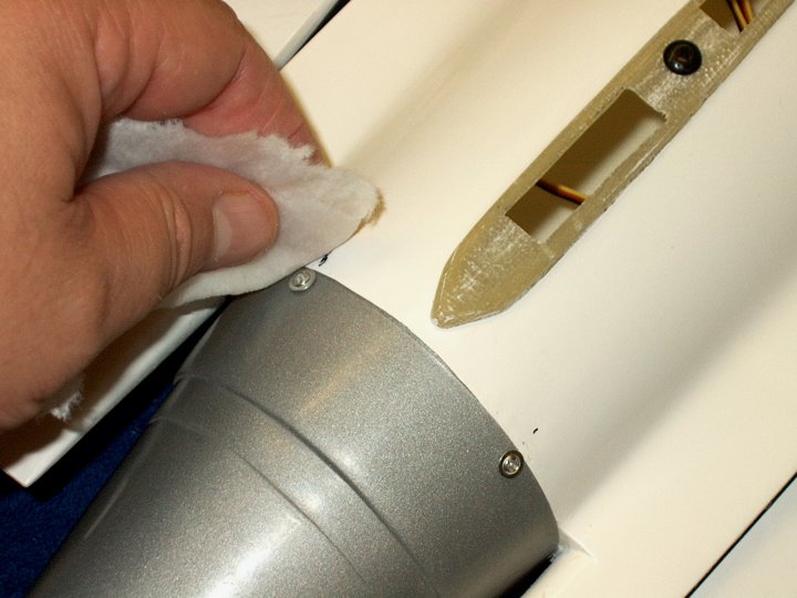
216 - Easily thread the screws in the
first time as they are cutting threads into the ply plates.
Install them until flush | |
217 - Use denatured alcohol and a paper
towel to remove the marks | |
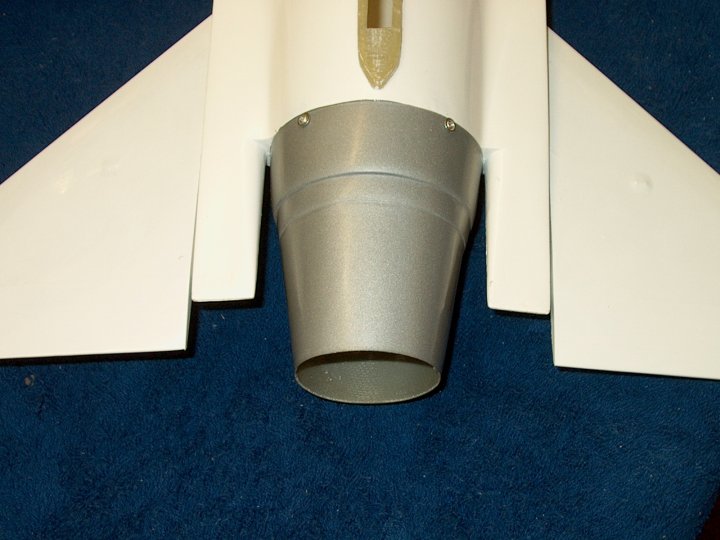
218 - Tailcone assembly completed
| |
219 - A 1/16" pilot hole is drilled in the
center of the vertical stab area | |
220 - The hole is opened with a 1/4" drill
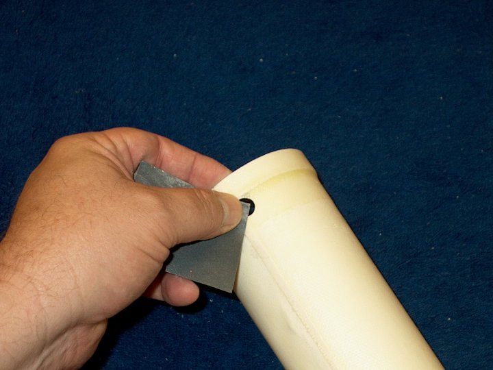
bit | |
221 - A small rubber grommet is installed
for the antenna wire to pass through
| |
222 - The inside of the vertical stab is
sanded with 60 grit for better glue purchase
| |
223 - The rear is heavily sanded to try
and make it even. The one in the box had a warped bottom cut
to the stab | |
224 - The front also needed sanding but
care was taken as to not take off too much. The Vertical Stab
is ready to install | |
225 - Tape is placed around the vertical
stab area to keep it clean from epoxy
| |
226 - Epoxy is applied to the vertical
stab inside and the fuselage area. Use only 5 minute
epoxy! | |
227 - This is the difficult part. You need
to hold the fin in place while the epoxy sets...this is why
you need to use 5 minute epoxy. Keep plenty of paper towels
and denatured alcohol available, install the fin, squeeze in
the sides, then use an alcohol soaked paper towel to clean up
the excess and hold in place. Make sure the fin remains
vertical. As stated, there is a lot to do, so be sure you know
the steps and have it all planned ahead of time
| |
228 - Once the epoxy sets but is still
soft, remove the masking tape | |
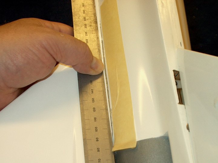
229 - A ruler is used to scrape away any
excess soft epoxy | |
230 - If you plan on painting your model,
you can use fine sandpaper to lightly sand the fin area. Skip
this step if yours is pre-painted | |
231 - The other side is scraped of soft
epoxy | |
232 - A spot in the fin below did not
adhere do to the way the fin was cut
| |
233 - Masking tape was added to minimize
the mess and fresh epoxy was scraped under the seam
| |
234 - The excess epoxy is removed
| |
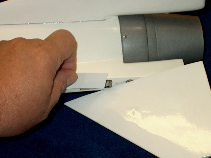
235 - The side is shown being pushed in to
indicate the spot that did not adhere
| |
236 - A towel with alcohol was used to
clean up the excess epoxy | |
237 - A ruler is used to hold the side
against the molded fuselage former while the epoxy sets
| |
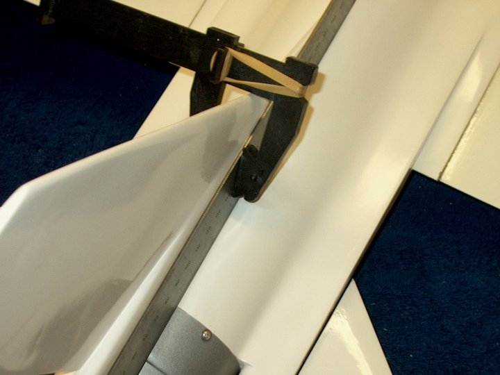
238 - A clamp was used to hold the ruler
in place | |
239 - Vertical Stab installation
completed | |
240 - The Stab should be perpendicular to
the fuselage | |
241 - Tape is once again added to the
fuselage around the stab area | |
242 - A fillet of epoxy is applied with a
toothpick | |
243 - Use your finger to make a nice
fillet around the stab | |
244 - The other side is done
| |
245 - Excess epoxy is removed to form a
small fillet. Remove the tape when finished and before the
epoxy sets | |
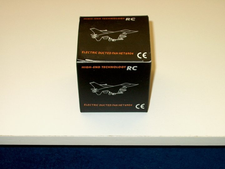
246 - The HET-RC EDF 6904 Minifan
| |
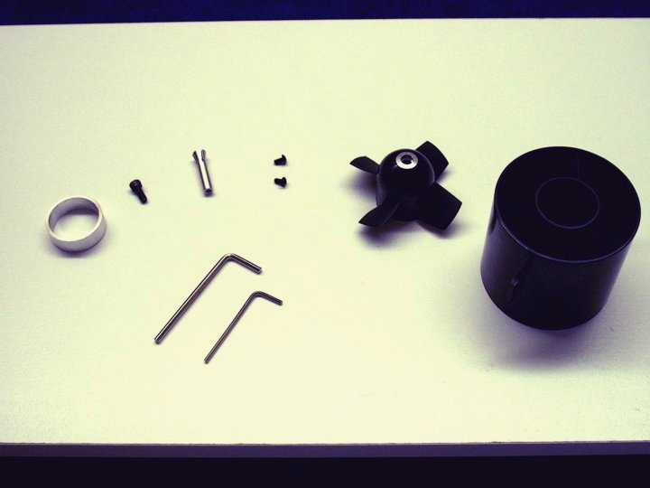
247 - The components of the HET minifan
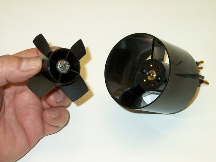
| |
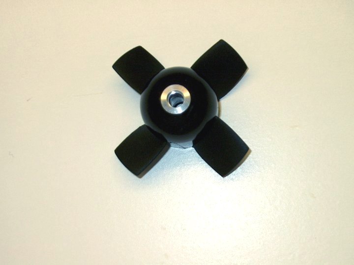
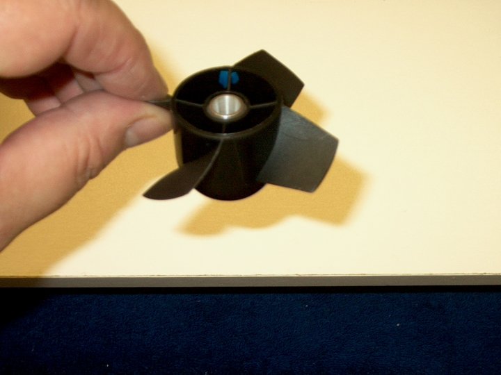
248 - The fan comes with the hub molded
together as one piece | |
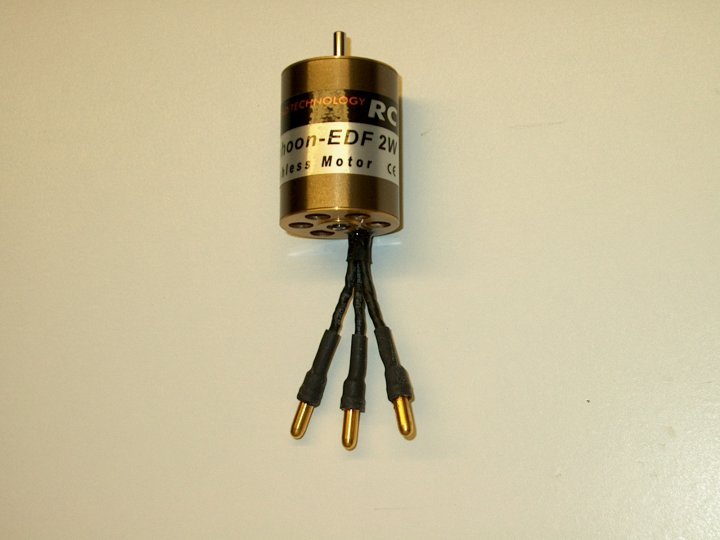
249 - A HET-RC 2W motor will be used to
power the model | |
250 - The ring that comes with the fan can
be placed over the rear. Note that the inner lip will insert
into the back of the fan housing. The ring was not used in
this build | |
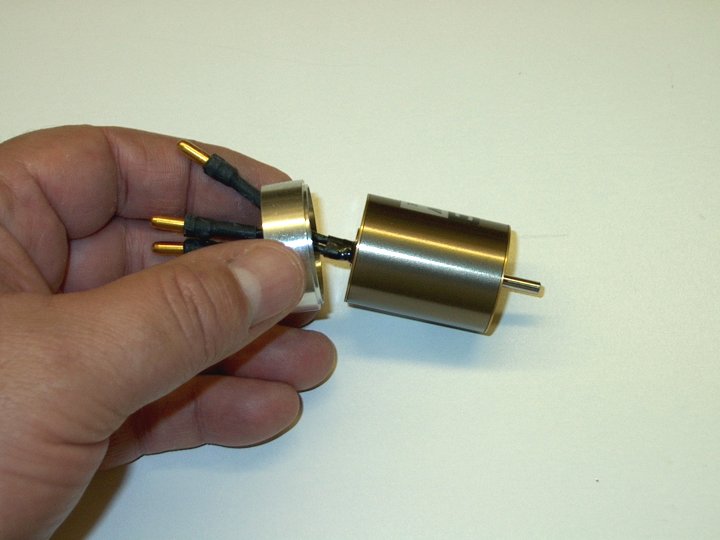
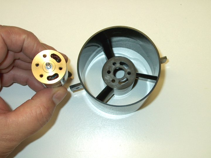
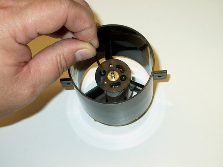
251 - Motor is test fit in the fan housing
and fit well | |
252 - As you can see, the housing was made
for this motor. Note the two kidney shaped slots in the motor
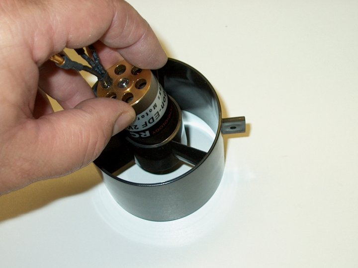
and the housing | |
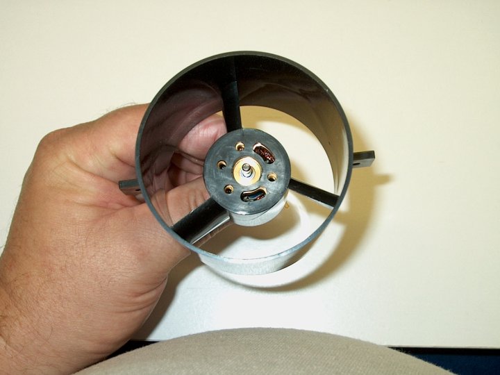
253 - The motor is installed with the
slots aligned with the motor. these will help provide some
cooling | |
254 - Some blue Loktite is applied to the
motor threads only and then wiped clean on the surface. Do not
apply Loktite to the bolts as it can touch the sides of the
mounting holes when installed and attack the plastic
| |
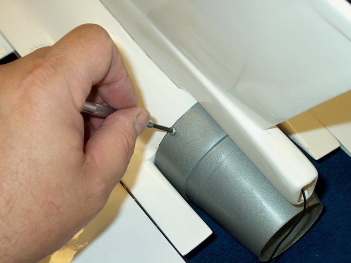
255 - The 3mm x 6mm bolts that came with
the fan are installed to retain the motor and tightened using
the supplied allen wrench | |
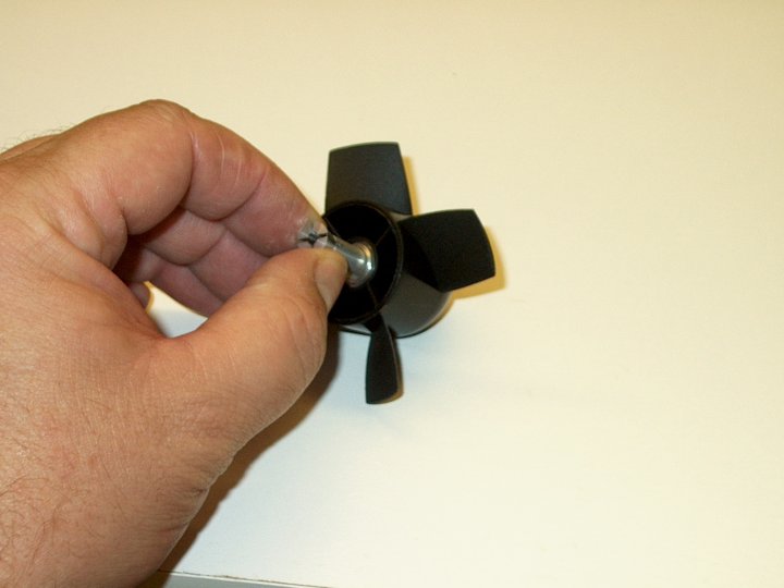
256 - Photo shows the shaft adapter and
how it fits inside the fan unit | |
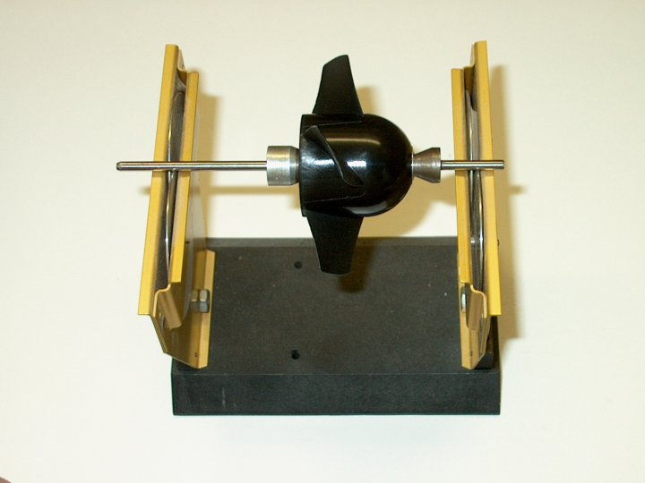
257 - The fan comes pre-balanced but was
still checked to confirm | |
258 - The blue spot shows the area that
was pre balanced at the factory | |
259 - The fan and housing prior to
installation | |
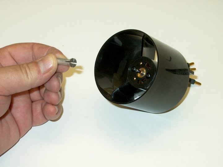
260 - Install the shaft adapter
first | |
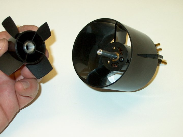
261 - Next, install the fan unit
| |
262 - Seat the fan flush for now
| |
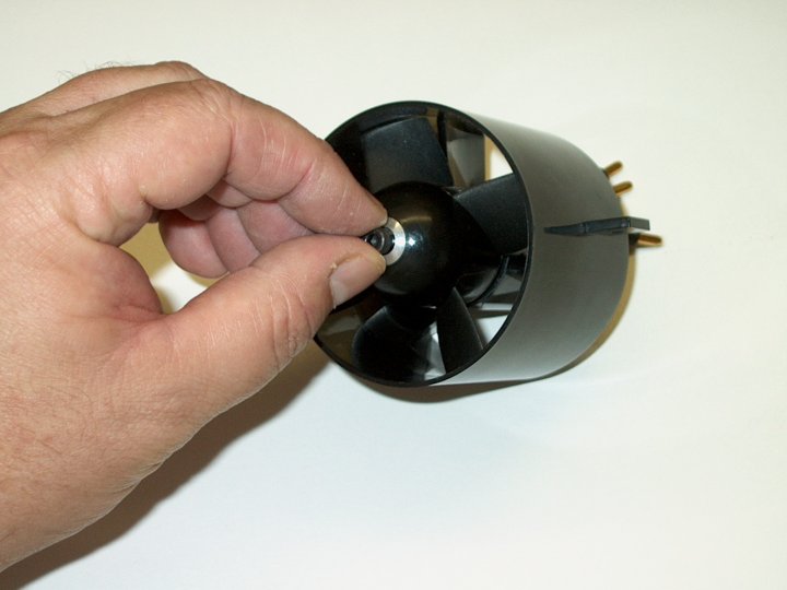
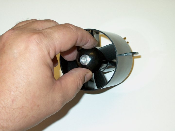
263 - Install the front hex bolt that
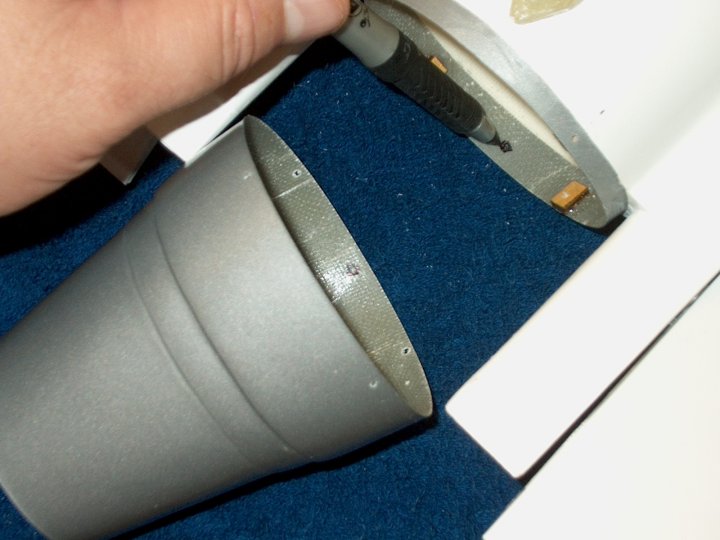
retains the fan | |
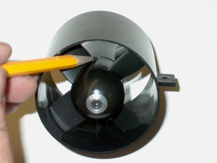
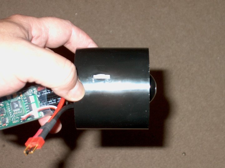
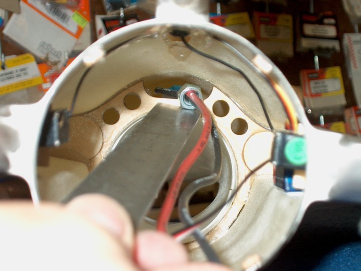
264 - Before tightening, pull the fan unit
away from the rear of the housing as shown by the pencil so it
will not rub | |
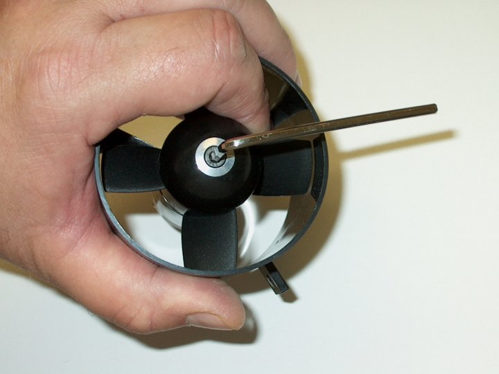
265 - Tighten the bolt with the supplied
wrench and check the fan to make sure it is not rubbing on the
housing | |
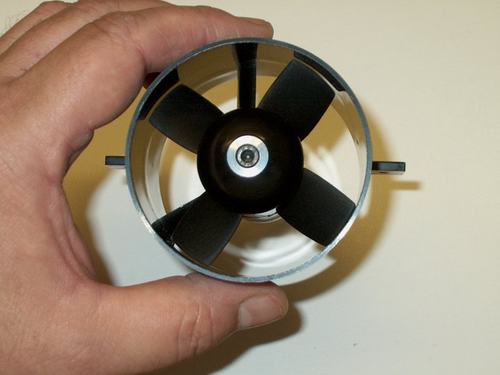
266 - Make sure the clearance appears even
on all fan blades and check for rubbing
| |
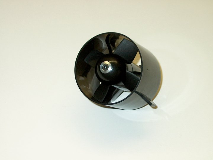
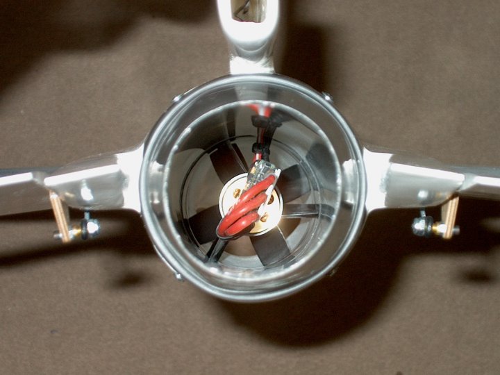
267 - The HET-RC 6904 mini Fan
Assembled | |
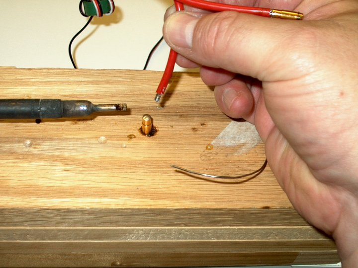
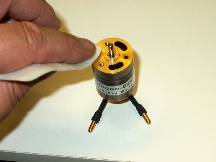
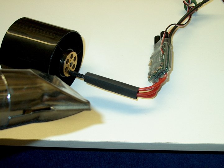
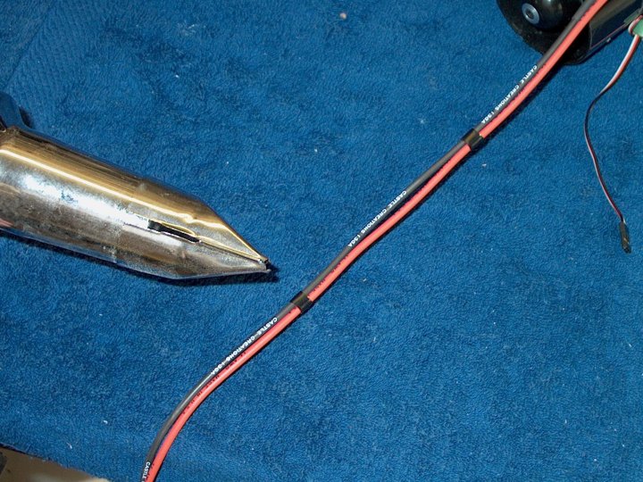
268 - Connectors are soldered to the motor
and ESC. This allows you to swap your motors and ESCs around
easier without taking apart your model
| |
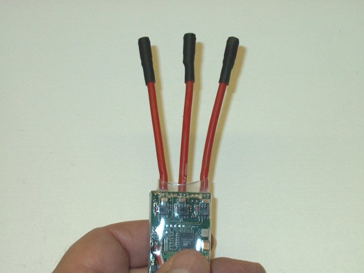
269 - Motor ends of the ESC are covered
with heatshrink to prevent shorts | |

270 - Power wires for the ESC also have
connectors installed | |
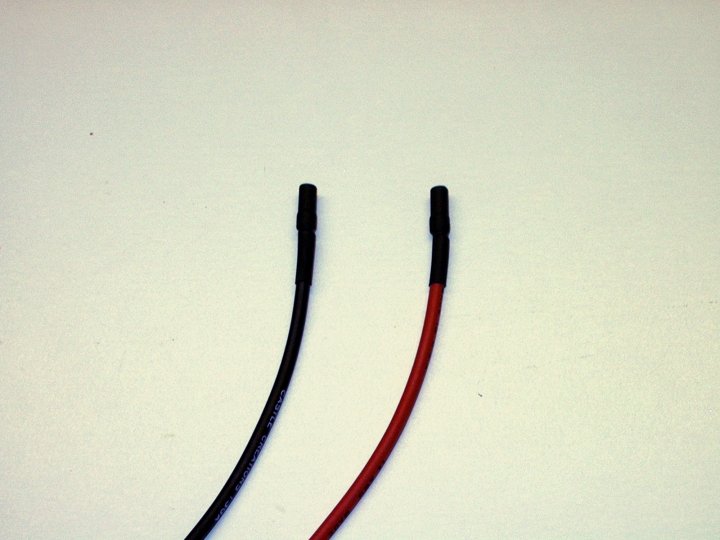
271 - Power wires to the battery with
connectors and heatshrink. Always install so the sockets such
as those shown below are coming from the battery source. This
way, no matter where you disconnect down the line, you will
not risk a short like you would if plugs were
substituted | |
272 - Plug in the three wires of your
motor into the ESC sockets. A large piece of heatshrink is
then installed over these wires at the plug asssemblies To
prevent them from coming apart in the air turbulence
| |
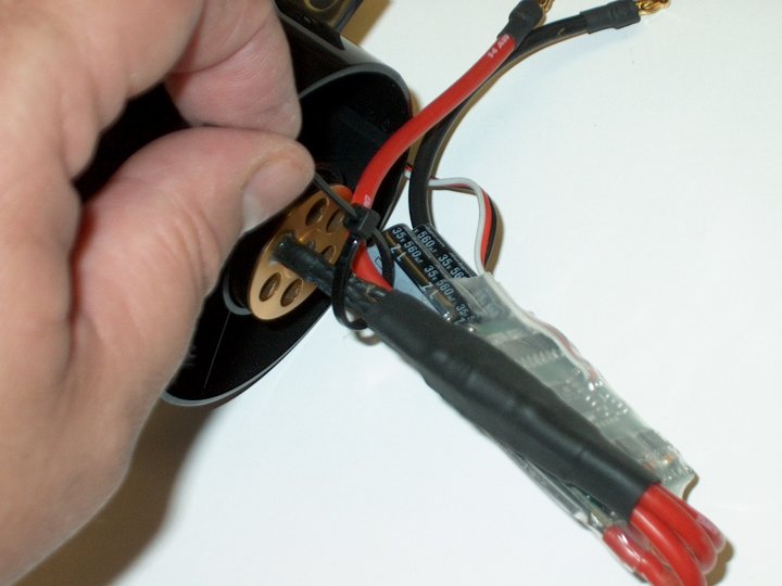
273 - A wire tie is used to secure and
anchor the front of the ESC | |
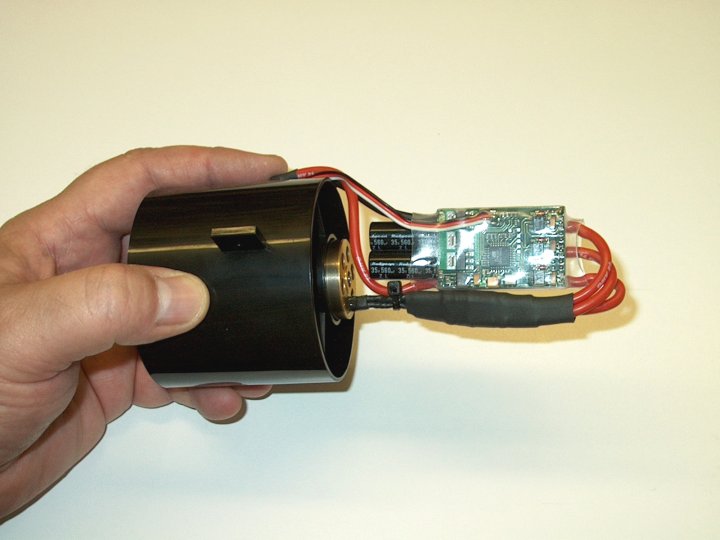
274 - Fan, Motor and ESC assembly
completed and ready to install in the Jet
| |
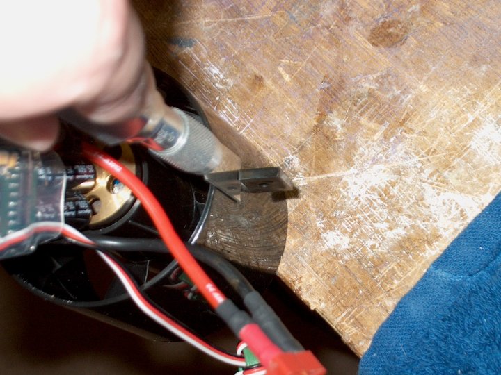
275 - The instructions call for you to
remove the mounting tabs of the fan as seen in the pic
| |
276 - Tabs have been removed
| |
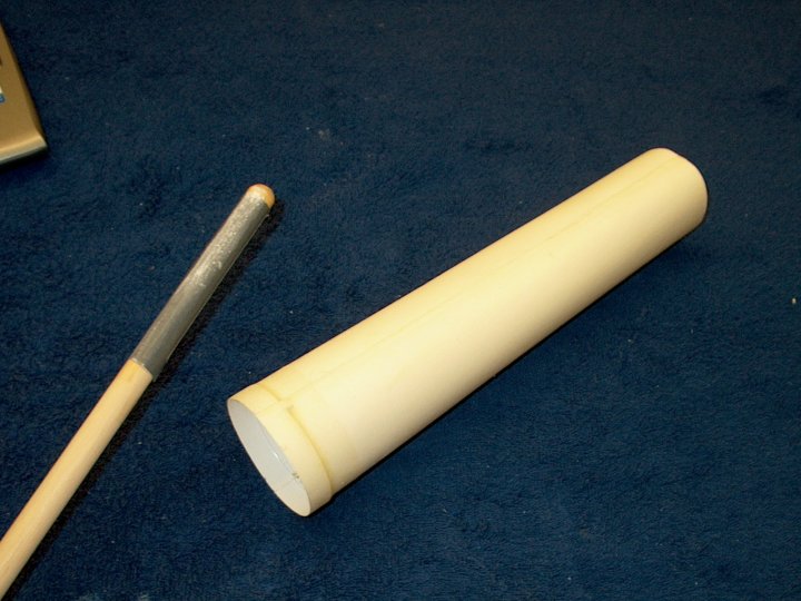
277 - Fine grit sandpaper was wrapped
around a dowel and used to smooth the rough spots in the
fiberglass exhaust duct | |
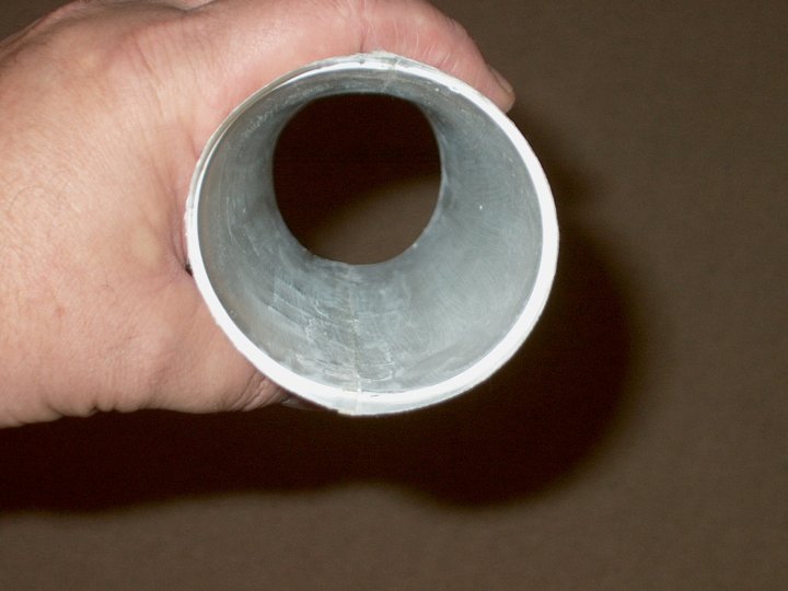
278 - Exhaust duct after sanding
| |
279 - The outside lip of the fan is sanded
to round the edge and make it easier to install
| |
280 - Fiberglass duct is temporarily
installed to the fan assembly | |
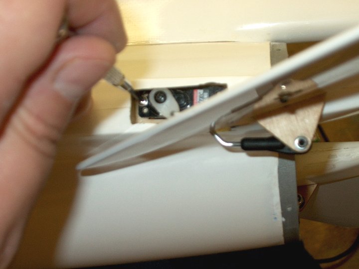
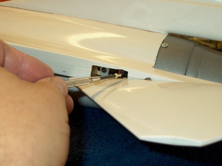
281 - A servo had to be loosened so the
fan and duct could pass by from the rear
| |
282 - Work the fan past the servos
| |
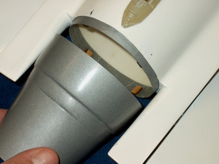
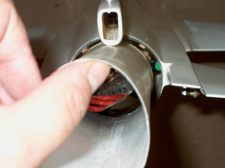
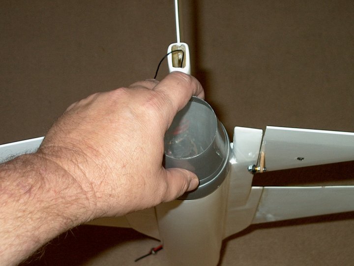
283 - Insert the fan into the forward
intake duct. It may seem a bit difficult at first to get it to
engage the intake duct. Keeping the bottom of the exhaust duct
low enabled it to slide in better | |
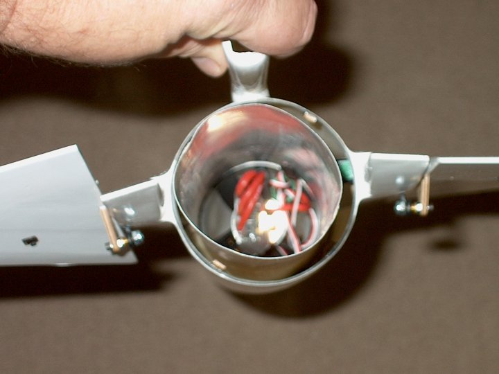
284 - Pic shows duct fully seated in the
intake. It will need to be trimmed to length
| |
285 - Keep the Tailcone centered and
measure the difference between the mounting holes on the
fuselage and the tailcone. This is how far you will need to
trim the exhaust duct | |
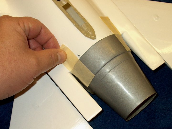
286 - A 1" wide strip of paper is wrapped
around the exhaust tube and a mark is made at a distance from
the end that you measured in the previous step
| |
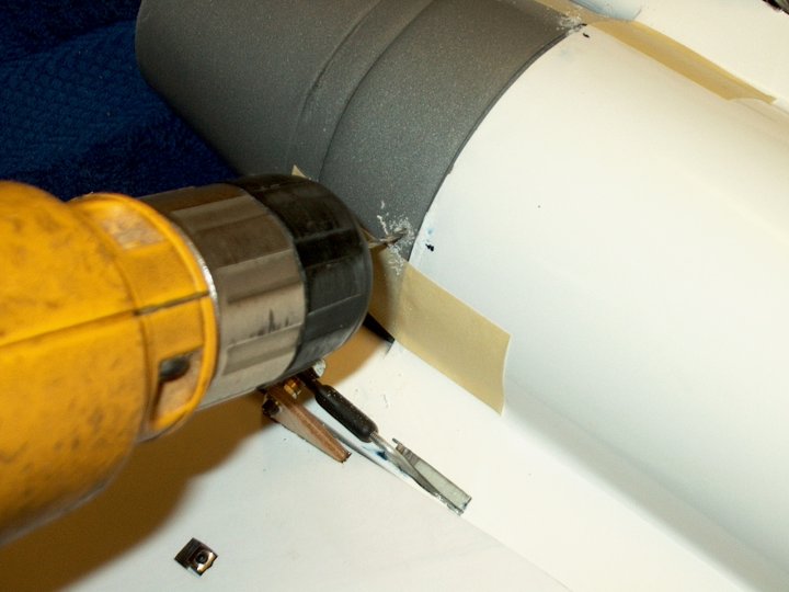
287 - A cutting tool or knife can be used
to trim the exhaust tube. Cut it a bit short of the line so
you can fine sand the excess tube to the line
| |
288 - Sand the tube to the line
| |
289 - Drill a hole in the front of the
tube at the top location | |
290 - Open the hole up to about 3/8" for
your ESC wires to pass | |
291 - The hole should be sanded to remove
sharp areas | |
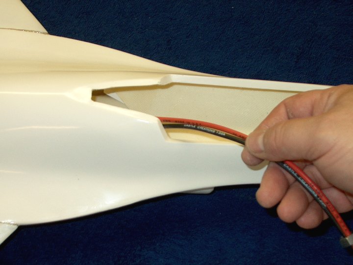
292 - The ESC wires are passed through the
hole | |
293 - Packing tape is used to fasten the
exhaust tube to the fan assembly | |
294 - Fan and exhaust tube shown with
wires coming from the top. Notice there is a slight upward
angle , which was required to have the exhaust center in the
fuselage rear | |
295 - Tape is used to secure the ESC
wires | |
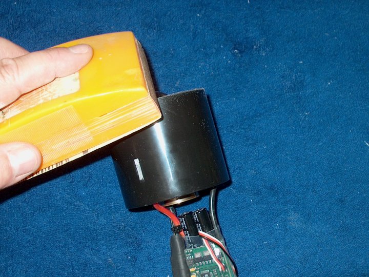
296 - Temporarily fit the unit in the
fuselage. Make sure the exhaust rear is centered in the
fuselage. If not, remove the unit, loosen the tape on the fan
and re-adjust/tilt slightly until centered
| |
297 - Check the fit of the tailcone. The
Exhaust tube may still need some fine trimming
| |
298 - Make a mark on the exhaust tube
again for final trimming | |
299 - Scissors are used to fine trim the
exhaust tube | |
300 - Check the tailcone fit and make sure
it is flush | |
301 - Check for buckling in the exhaust
tube and sand more if needed. It should be a nice tight
fit | |
302 - Rear exhaust area of the fuselage
shown | |
303 - The inside of the tailcone is
roughed up with 60 grit in the area where the exhaust tube
will touch | |
304 - Lightly rough up the outside of the
exhaust tube | |
305 - Apply a heavy coat of epoxy and
quickly install the tailcone | |
306 - Keep the fuselage vertical so the
epoxy runs down to the exhaust tube joint inside. Quickly
install the screws so the glue sets while the tailcone is in
the correct position | |
307 - Leave the fuselage in a vertical
position until the epoxy sets | |
308 - Once the epoxy has set, remove the
assembly | |
309 - Photo of the completed Fan
Assembly | |
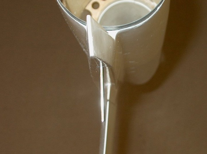
310 - Some additional epoxy was mixed and
poured in the tailcone joint for added strength
| |
311 - The power wires are installed and
heatshrink is added | |
312 - A couple small slices of heatshrink
are used to dress the cable | |
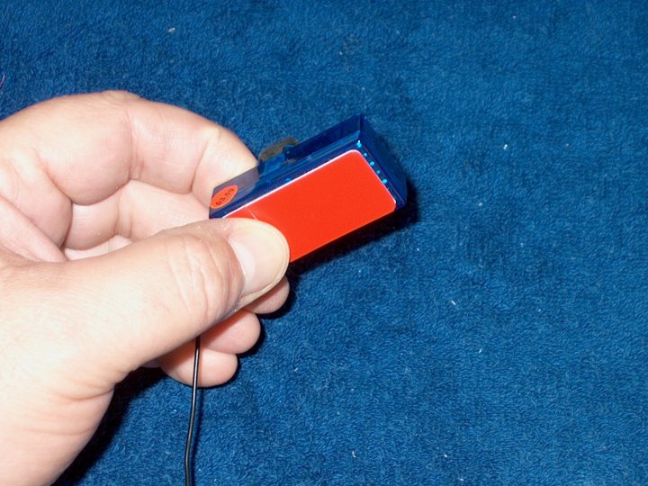
313 - Servo tape is added to the radio
receiver | |
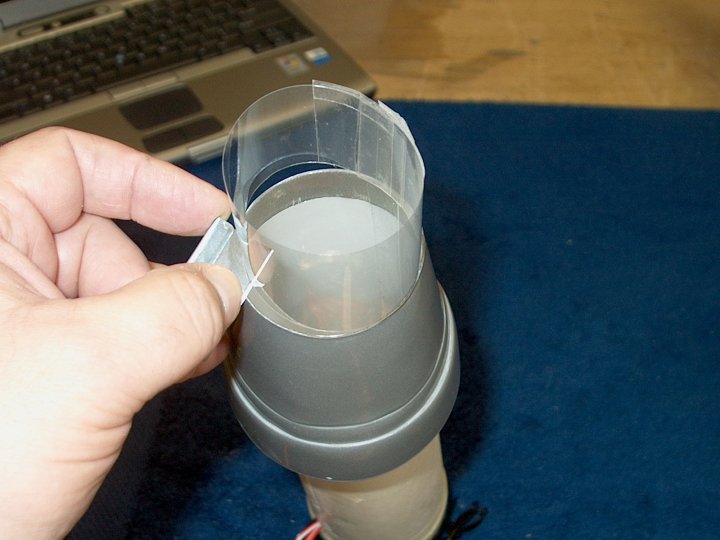
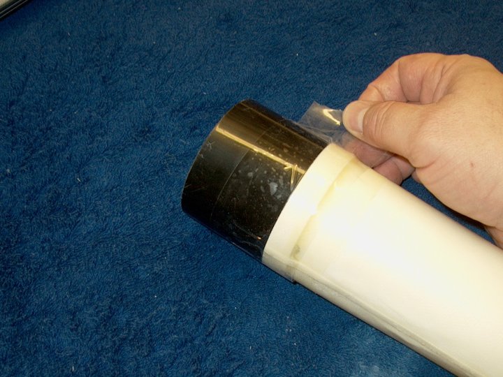
314 - This step is not necessary, but I
added a inner lexan thrust tube as it made for a smoother
walled exhaust, a more even transition to the tailcone and
should provide more efficient airflow
| |
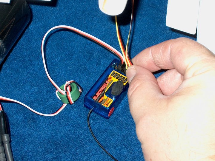
315 - Servo cables are installed in the
receiver | |
316 - The receiver antenna wire is run
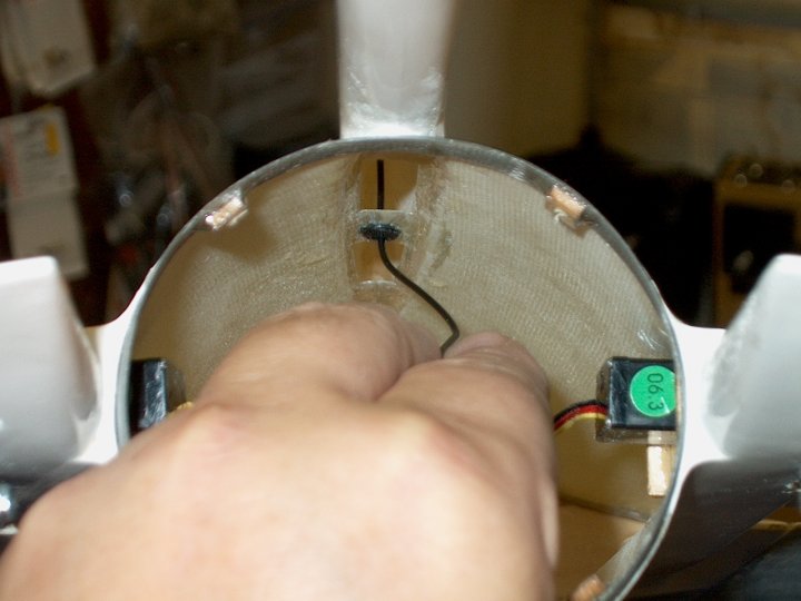
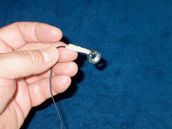
through the grommet | |
317 - A nut is taped to the wire to help
with routing | |
318 - The wire nut is installed in the
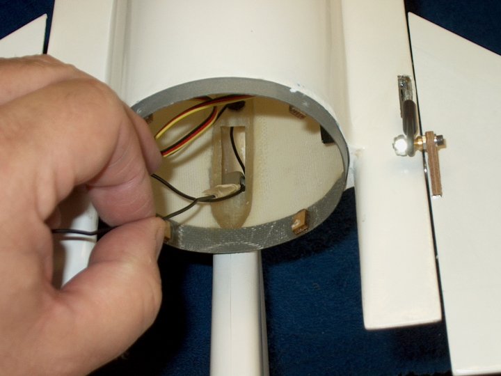
vertical stab area | |
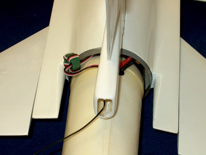
319 - The nut helps route the wire out the
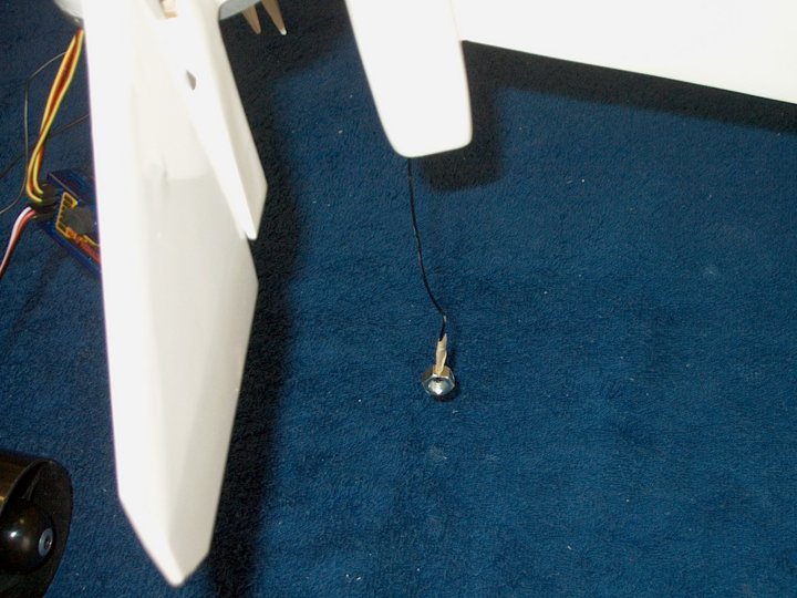
rear of the vertical stab | |
320 - The receiver is prepared for
installation | |
321 - The receiver is installed on the
right side of the fuselage just in front of the servo tray. It
is a bit tight, but can be reached | |
322 - Receiver installed in place
| |
323 - Tape is used to retain the servo
wire on the other side | |
324 - Tape is shown retaining the servo
wire so it doesn't snag when the fan assembly is
installed | |
325 - A nut is used to help route the
power wires to the front of the fuselage
| |
326 - Install the fan assembly in the
fuselage, taking care to route the wires
| |
327 - Keep removing the slack out of the
power wires during installation | |
328 - Set the fan assembly in the forward
intake | |
329 - Installed the tailcone screws to
hold the fan assembly in place | |
330 - Re-install the screws for the servo
that was loosened | |
331 - Fan Assembly installed in
fuselage | |
332 - Trim the excess length from power
wires | |
333 - An Ultra Plug is installed on the
power wires | |
334 - Power plug installation
completed | |
335 - The canopy is trimmed with a pair of
scissors | |
336 - Trim a little at a time and check
the fit. Leave enough on the sides for gluing
| |
337 - Use epoxy or canopy glue to mount
the canopy to the frame. DO NOT glue the canopy in place if
you plan to paint it | |
338 - Canopy assembly completed
| |
339 - The model comes with magnets for the
canopy, but I opted for a more secure mount. Make sure the
canopy is centered in the rear and drill a 1/16" pilot hole
through the rear of the canopy and into the fuselage
| |
340 - A small piece of wood should be
epoxied under the fuselage area for more grip from the
screw | |
341 - A clamp is used to hold the ply
plate in place until the glue sets | |
342 - Only the top section of the canopy
is opened with a 1/8" drill and a #2 hex screw is used to
secure it | |
343 - A mark is made at 3.5mm from the
bottom of the fuselage and is the center for the Elevons.
Adjust the ball links so that they center at this mark
| |
344 - Elevator up is 11mm from the center
mark. The same applies for Aileron movement
| |
345 - Elevator down is 11mm from the
center mark. The same applies for Aileron movement
| |
346 - The servo openings are covered with
a piece of self stick monokote | |
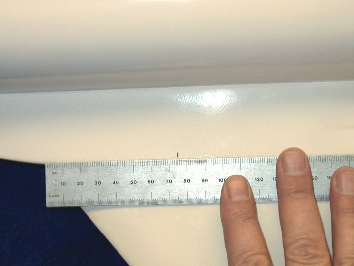
347 - CG for the model is set at 75mm
behind the wing root. Make sure your model balances before
flying | |
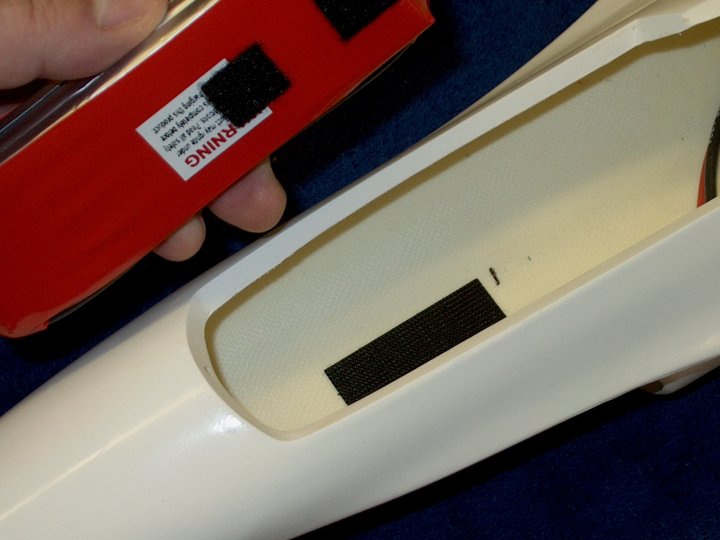
348 - Place your battery in the opening
and install the canopy. Move the battery around until CG is
found. Add a black mark to show the rear location of the
battery for the model to balance at CG. A small strip of
velcro is used to hold the battery in place. Do not use large
strips as you can damage Lipos when removing them
| |
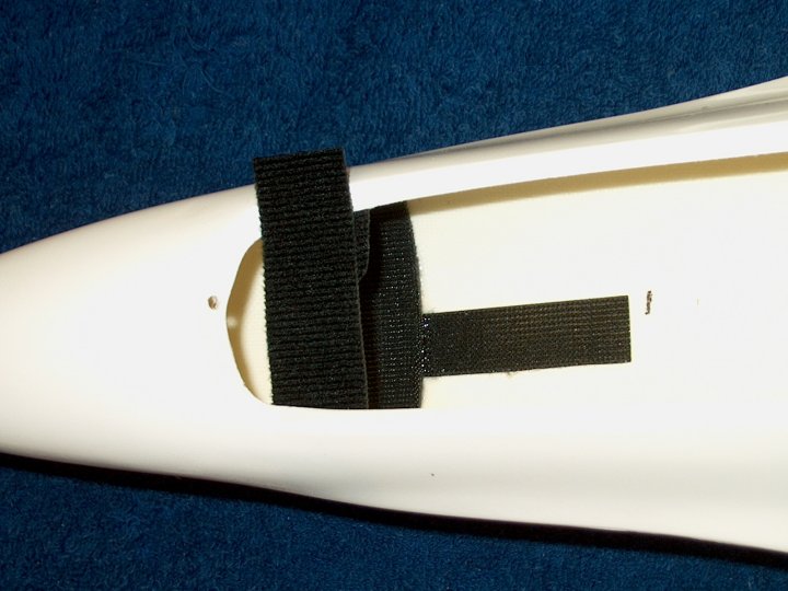
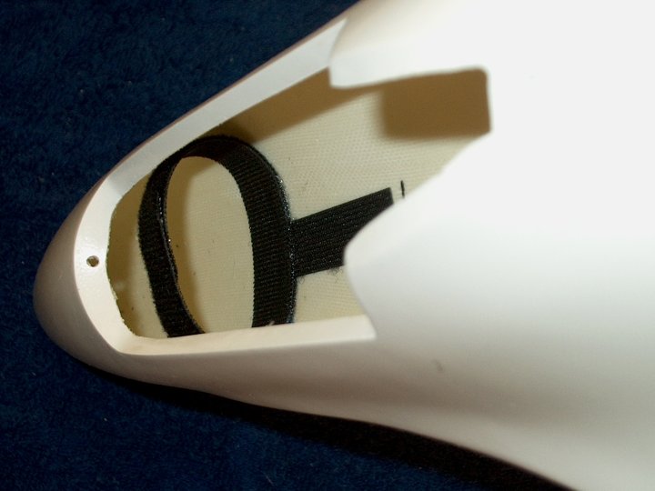
349 - A velcro strap is epoxied to the
bottom of the fuselage and actually retains the battery, while
the small velcro strip prevents it from shifting around
| |
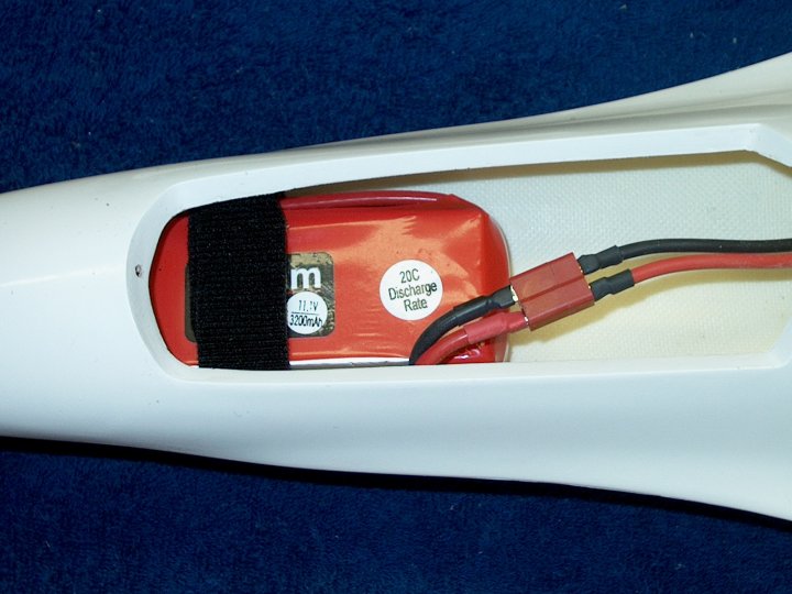
350 - Battery shown installed in
place | |
351 - Battery retention completed
| |
352 - The bungee hook is roughed up with
60 grit at the end that glues into the fuselage
| |
353 - A mark is made 25mm from the intake
seam on the bottom of the fuselage. This is the location of
the ply plate for the bungee hook | |
354 - A 1" strip of paper is anchored with
tape flush to the bottom of the fuselage and shown at the
bottom, then it is creased at the bottom on the other
side | |
355 - The paper is folded back so it is
flush to the bottom of the fuselage
| |
356 - The excess strip is removed
| |
357 - The strip is folded in half, then a
pencil is used to mark it at the fold
| |
358 - The strip of paper is taped to the
fuselage at each end and a mark is made for the hook at the
dead center mark on the paper | |
359 - A hole is drilled at the mark with a
5/64" drill bit | |
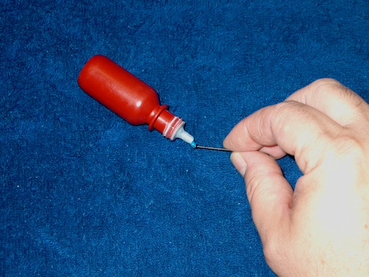
360 - A toothpick is used to push epoxy
into the drilled hole | |
361 - The hook is installed as shown and
the excess epoxy is removed | |
362 - Bungee hook shown installed
| |
363 - Make sure the hook is pointing
rearward and let the epoxy set | |
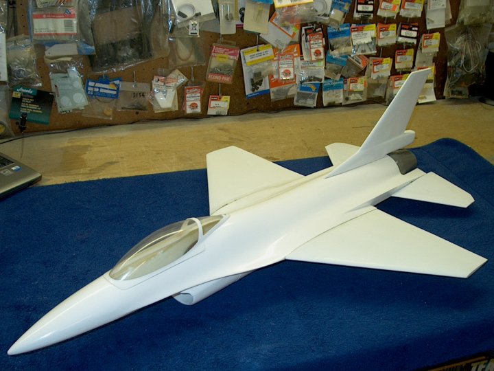
364 - The HET-RC F-16 Falcon from
Warbirds-RC Just add decals and paint(if necessary) and it's
ready to fly! | |
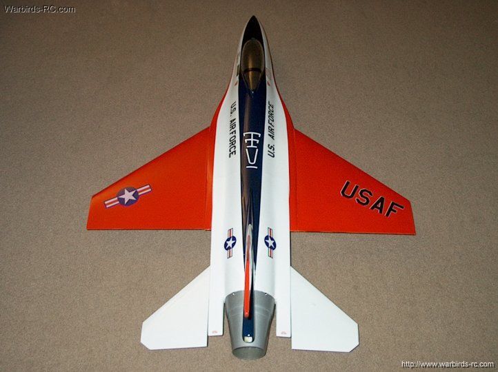
365 - Paint scheme used was for the F-16
Prototype, making it very visible in the air
| |
366 - Rear View showing decal
placement | |
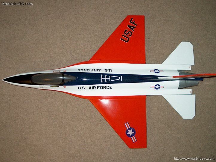
367 - Top View | |
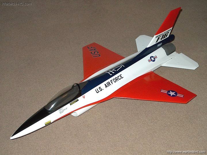
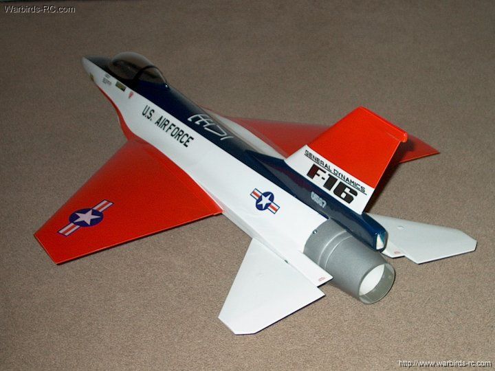
368 - The HET-RC F-16 Falcon EDF Jet
| |
|