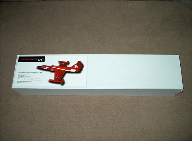
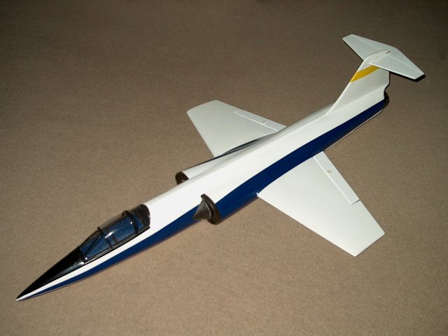
The HET-RC F-104 Starfighter Minifan EDF
as it comes from Markos at Warbirds-RC
| |
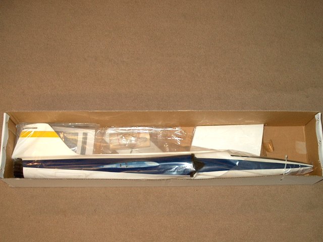
Opening the box reveals a well packed and
rather long model | |
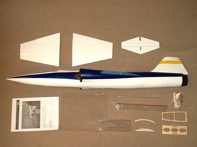
Every that comes with the ARF is shown
| |
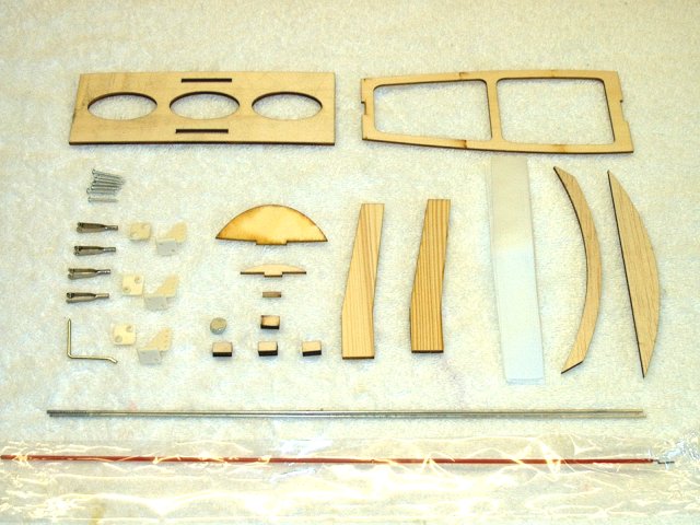
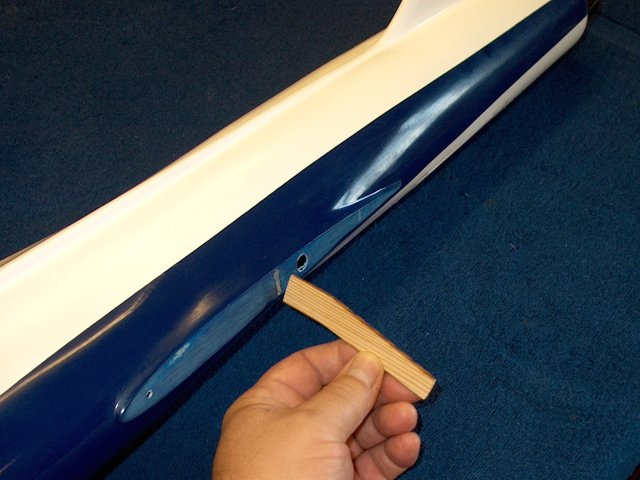
Shown is a closeup of the wood and
hardware included with the kit | |
The F-104 Starfighter fuselage
assembly | |
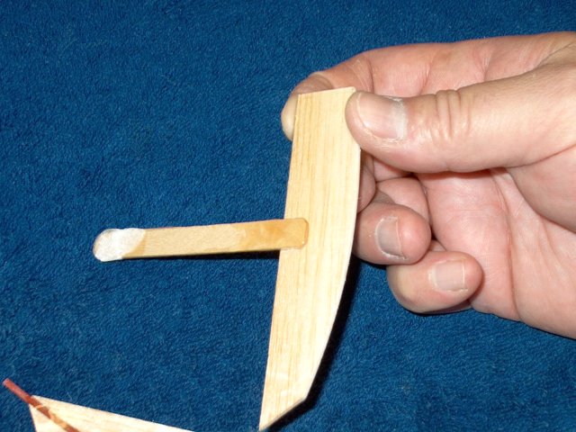
Mark a Left and Right main spar and
install them in each slot in the fuselage
| |
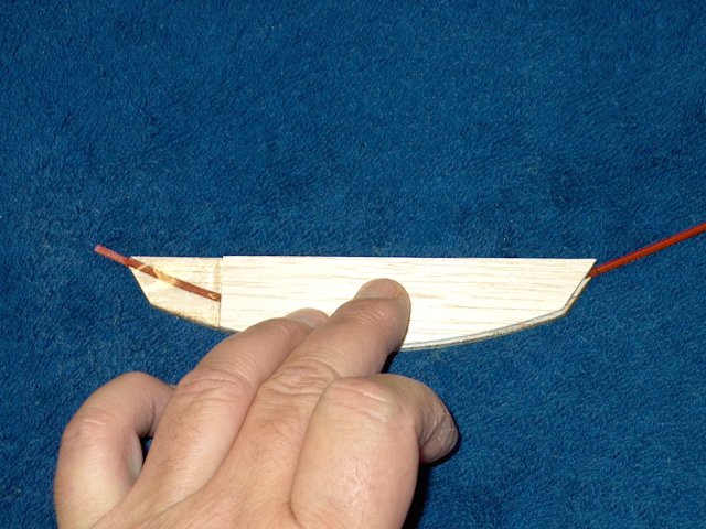
Install each wing and check that it is
fully seated on the wing saddle. If it will not seat flush
against the fuselage, sand the fuselage side of the spar, then
take a little off the end of the spar until the wing sits
flush | |
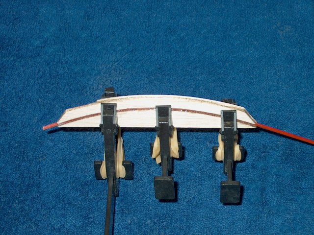
With each wing installed, check the
trailing edge for alignment and proper incidence. One wing was
off in this kit and needed adjusted
| |
When sanding the spar, make sure you sand
only enough on the inside so that it remains centered from top
to bottom in the slot, then perform the remaining sanding at
the tip. Use a sanding block to keep each end straight or the
wing can rock in its position | |
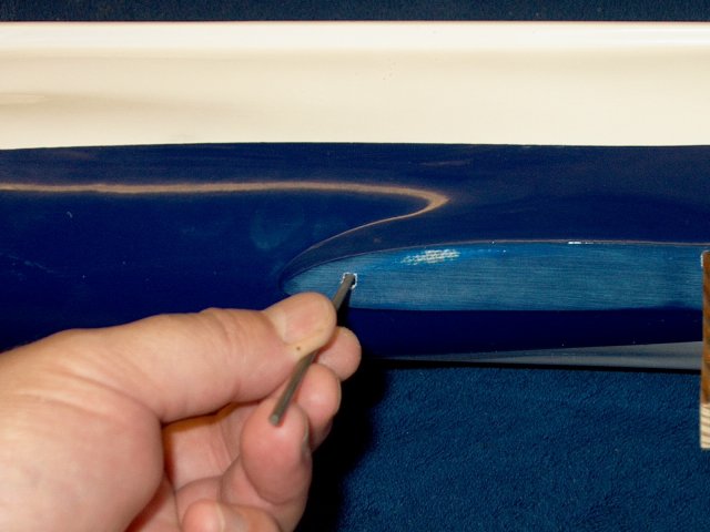
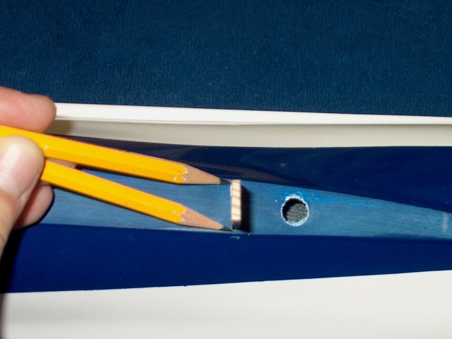
To adjust the wing, use a small round file
to elongate the wing dowel pin hole in the fuselage. Remove a
little at a time and check alignment. Continue to elongate
until the rear of the wing is centered and runs evenly across
the top and bottom of the fuselage wing saddle
| |
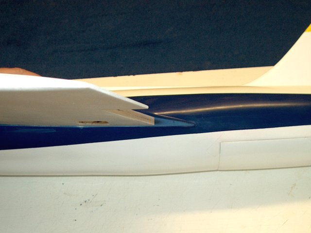
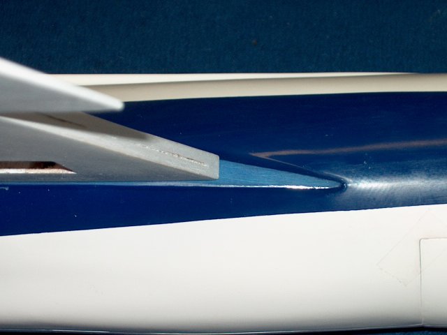
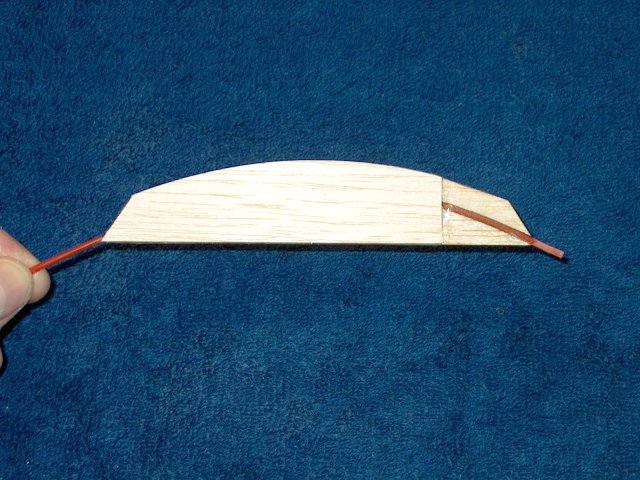
A properly aligned wing is shown
| |
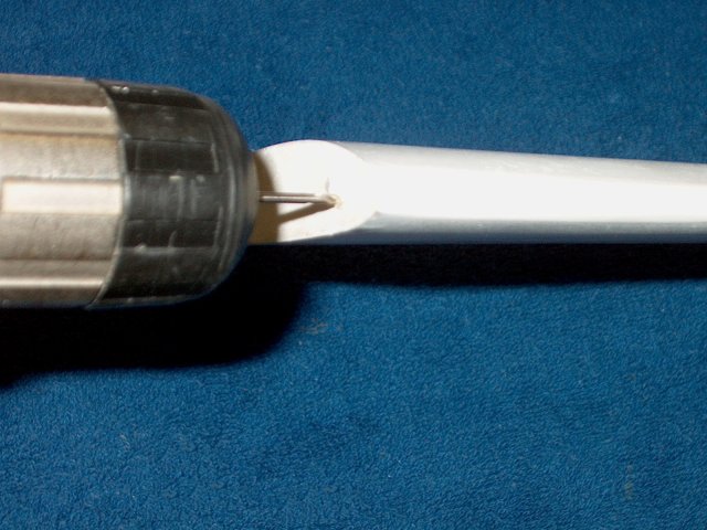
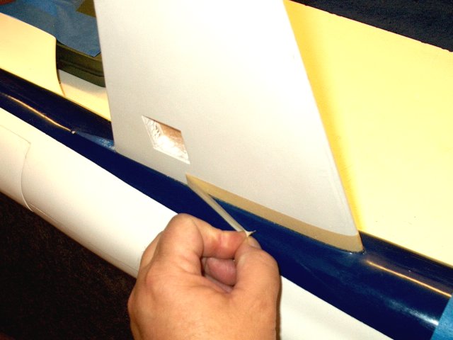
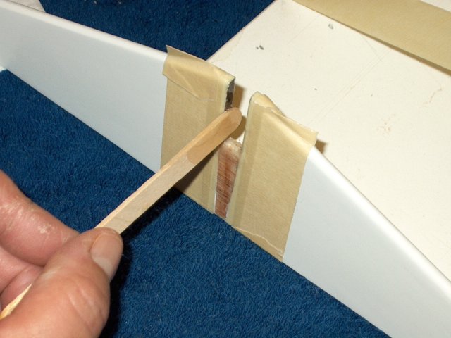
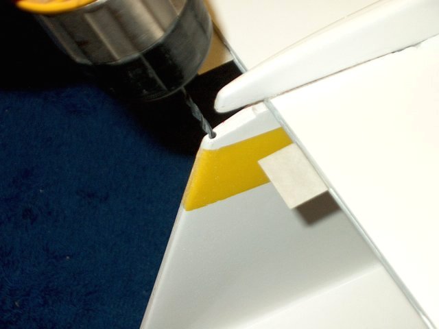
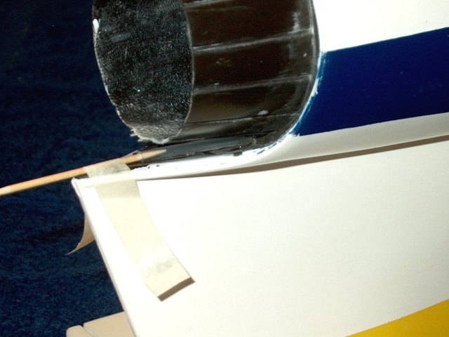
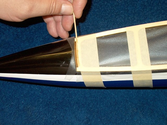
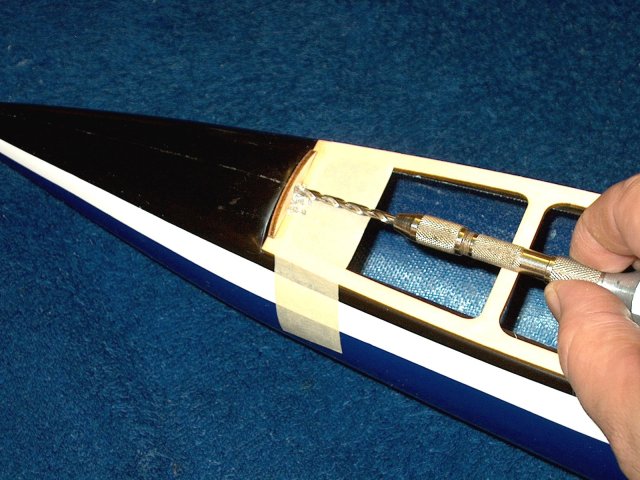
To tighten the dowel in the new hole,
drill a small hole above or below the wing depending on which
side you had to sand the slot | |
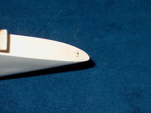
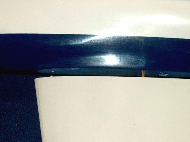
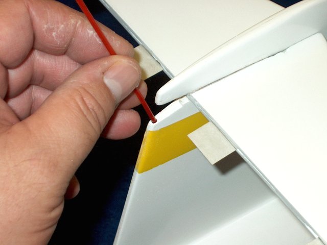
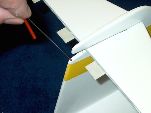
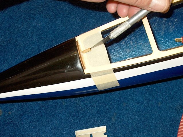
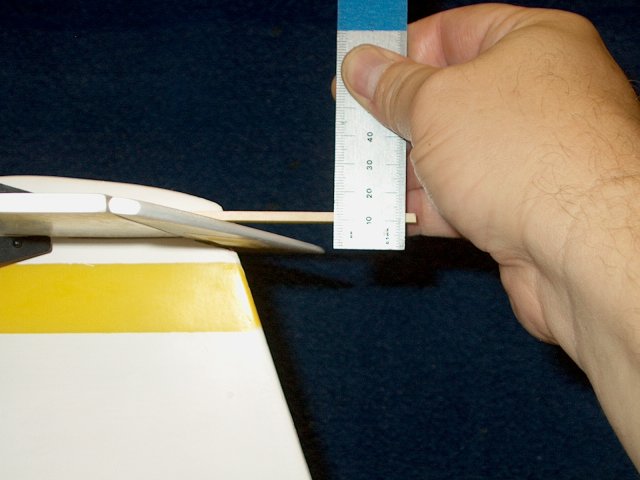
A toothpick is added and allows a snug fit
of the dowel pin into the elongated fuselage dowel pin
hole | |
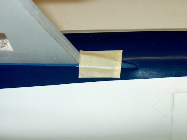
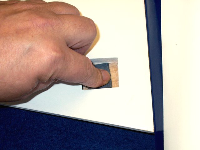
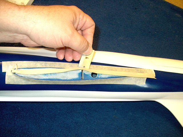
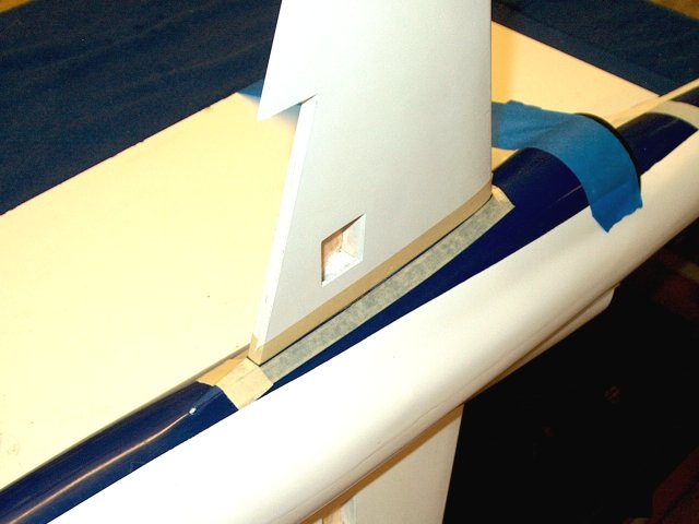
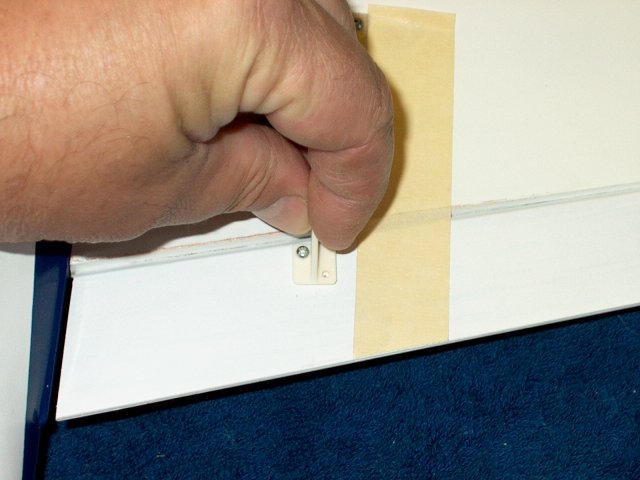
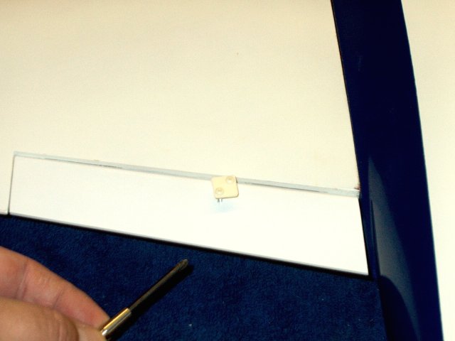
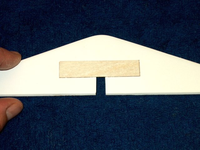
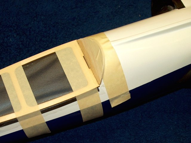
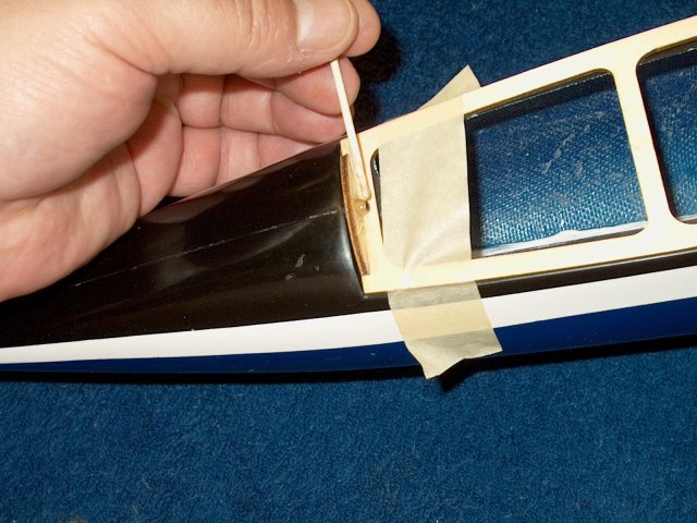
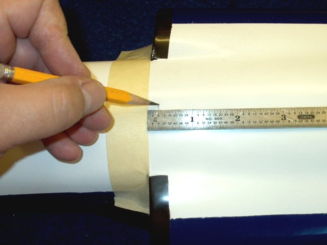
With the wing installed, apply some
masking tape even with the rear of the wing
| |
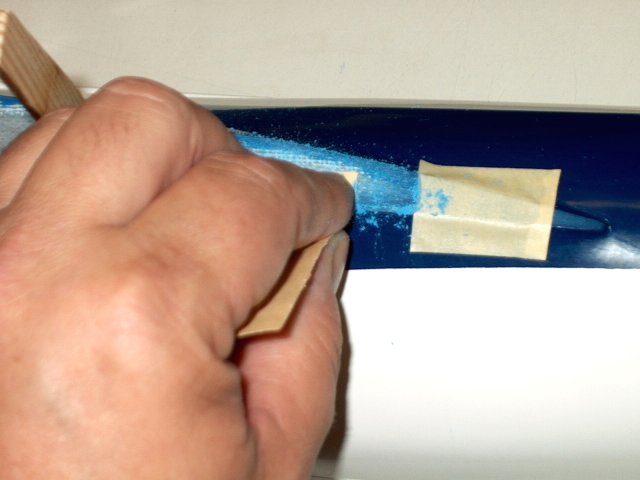
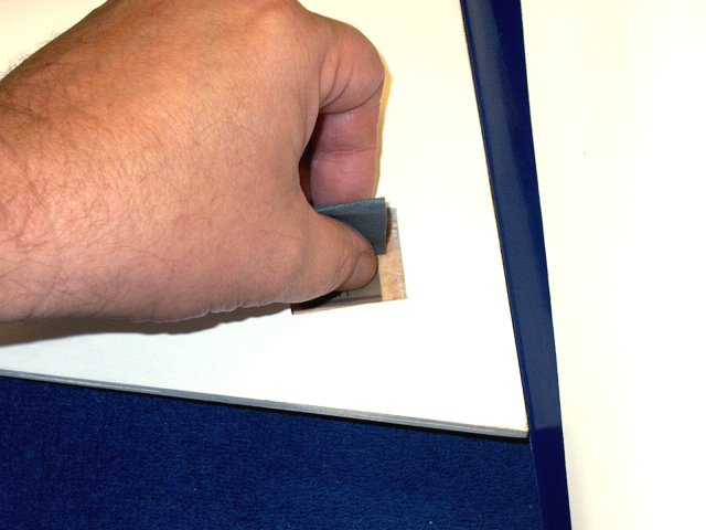
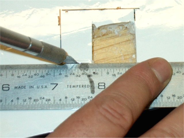
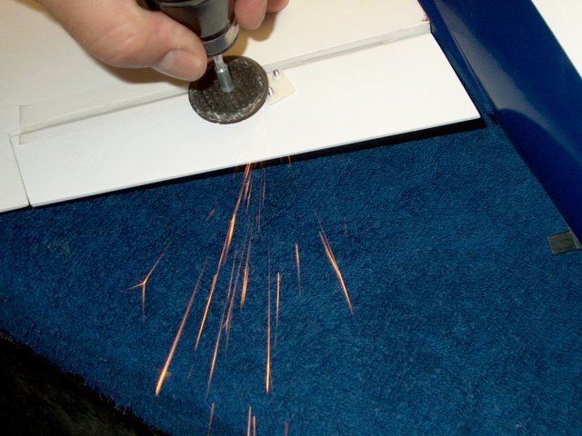
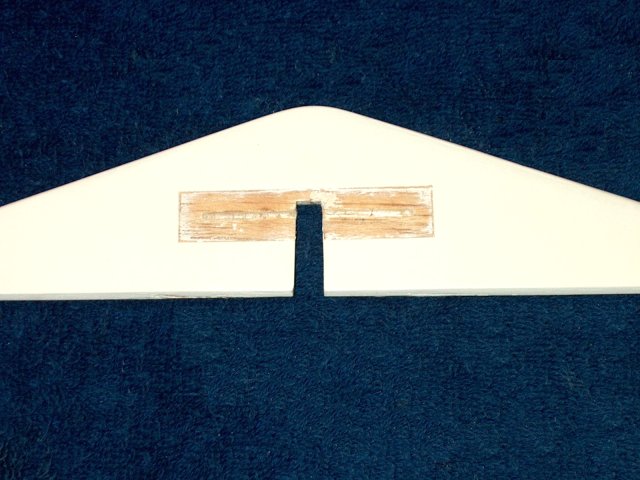
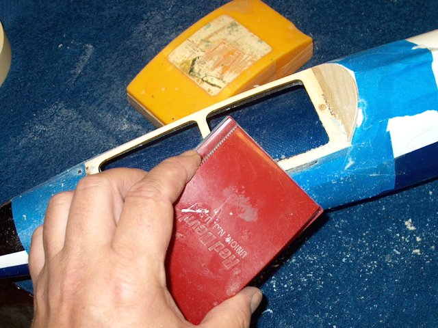
Sand this area up to the tape to remove
paint and allow for better glue purchase
| |
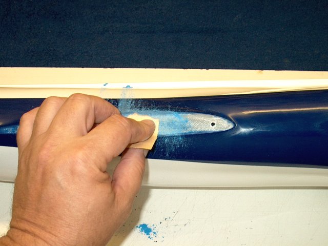
The rest of the wing saddle is sanded with
60-100 grit. Be careful not to remove too much, which will
weaken the saddle | |
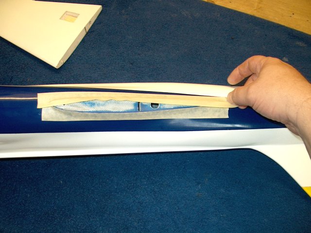
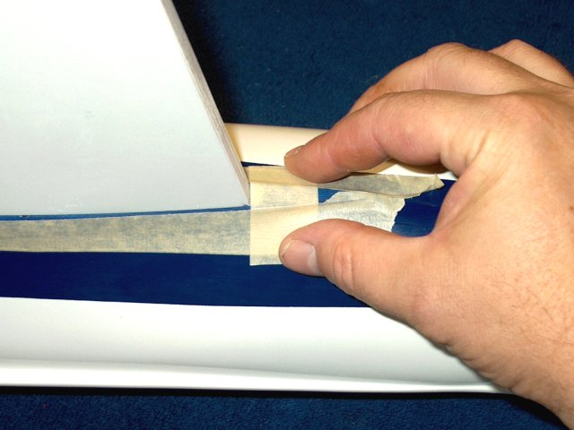
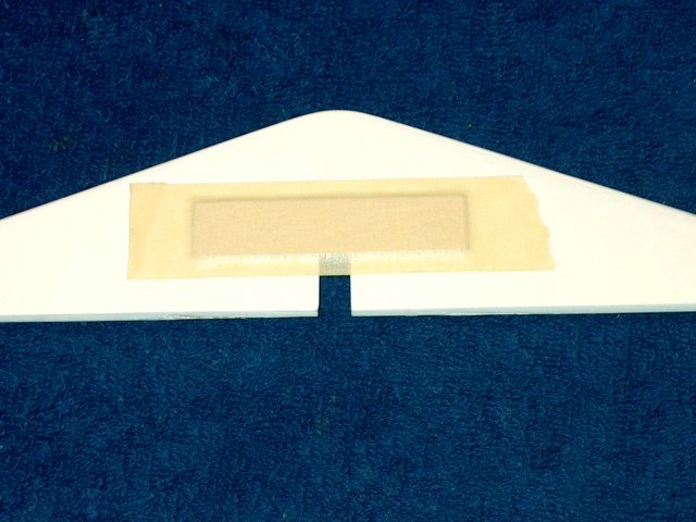
Masking tape is applied around the wing
saddles for both wings | |
Trim the tape flush to the gluing surface
of the wing saddle | |
Add a fresh piece of masking even with the
rear of each wing | |
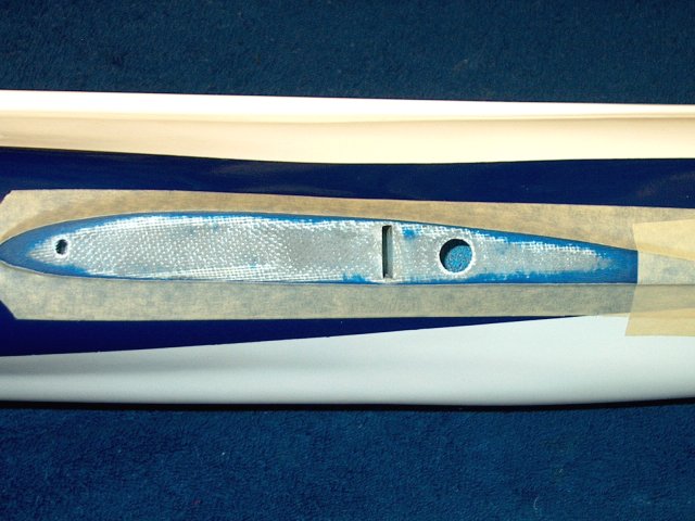
The wing area is shown ready for
epoxy | |
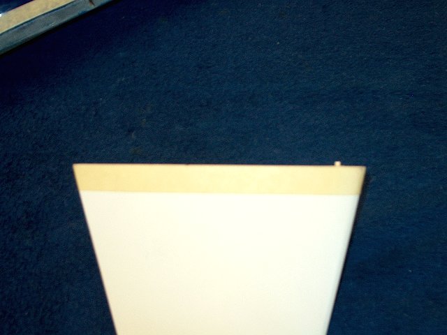
Apply masking tape flush to the end of
each wing. This will catch any epoxy spill over and keep the
wings clean | |
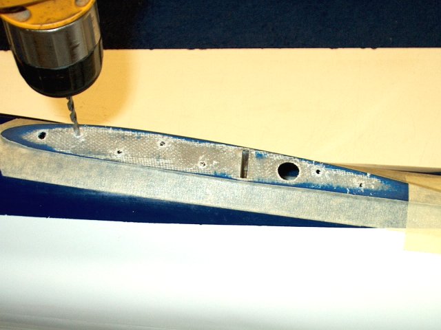
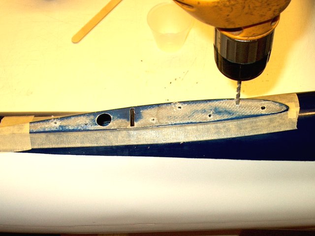
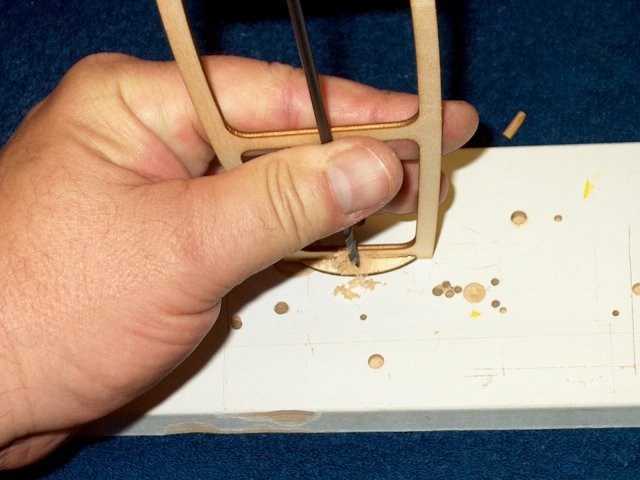
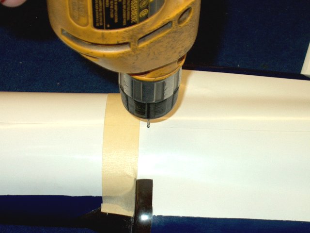
Drill some 1/8" holes in each wing saddle,
spaced about an inch apart and inside the glue area. This will
allow rivots to form and add strength to the joint
| |
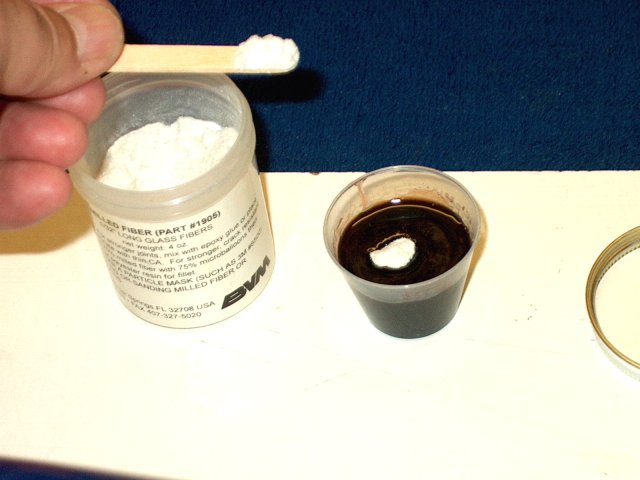
Mix some epoxy and set some of the mix
aside, then add some fiberglass mil to thicken the remaining
solution. Fifteen minute epoxy was used for each wing
installation | |
Apply the regular epoxy to the wing spar
slot in one wing | |
Apply epoxy to the spar in the area that
will be inserted into the wing | |
Install the spar in the wing and clean up
the remaining epoxy. Note that the epoxy may "hydraulic" in
the hole, so push and pull the spar a few times to work it in
so it is seated flush | |
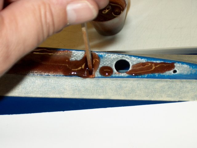
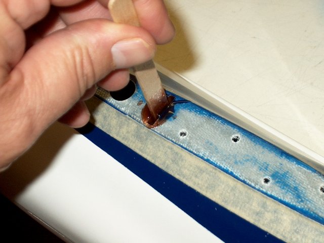
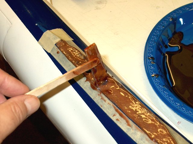
Use a stick to apply the thickened epoxy
mix to the wing saddle | |
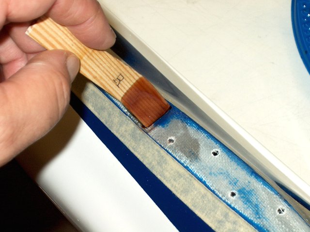
Apply regular epoxy to the exposed spar
area | |
Apply regular epoxy to the wing spar
area | |
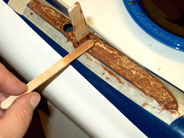
Apply regular epoxy to the remainder of
the wing in a thin film so it will soak into the spar
| |
Install the wing on the spar and flush to
the fuselage | |
Use denatured alcohol and paper towels to
remove excess epoxy | |
Wing is shown installed. Allow some time
for the epoxy to set | |
Drill holes in the second wing saddle as
shown | |
Install regular epoxy in the wing spar
slot on the fuselage | |
Apply regular epoxy to the spar and
install as shown. Make sure it hydraulics and bottoms out so
it sits flush inside the fuselage, then clean off the
excess | |
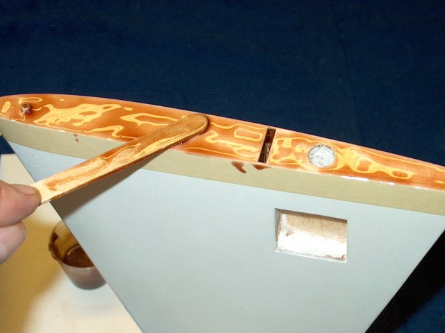
Apply thickened epoxy to the remaining
wing saddle | |
Use a stick to apply regular epoxy to the
exposed wing spar | |
Apply regular epoxy to the wing spar slot
and wing spar as shown | |
Install the second wing on the
fuselage | |
Remove excess epoxy with alcohol and paper
towels | |
Allow the epoxy on the second wing to
set | |
Remove the tape from each fuselage saddle
and wing | |
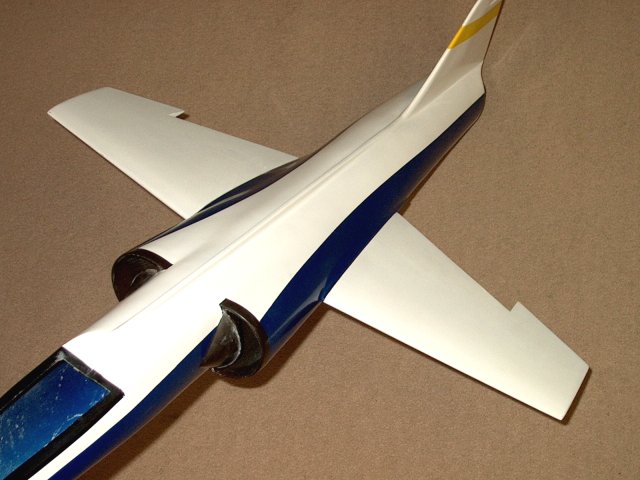
Wing installation shown completed
| |
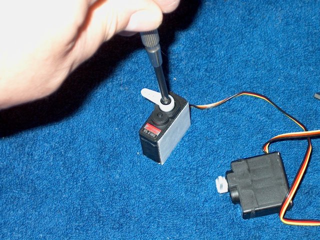
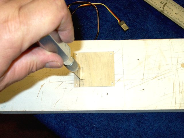
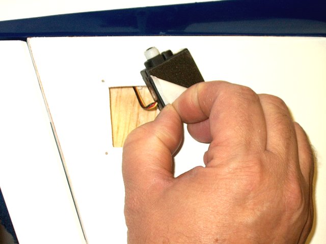
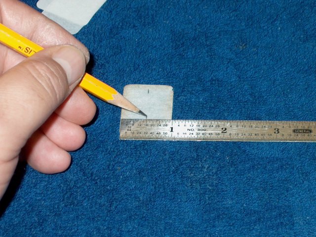
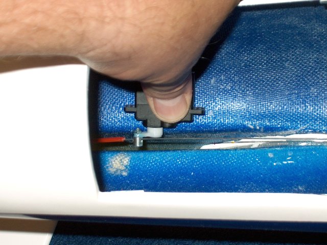
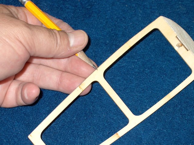
Construction begins with wing preparation
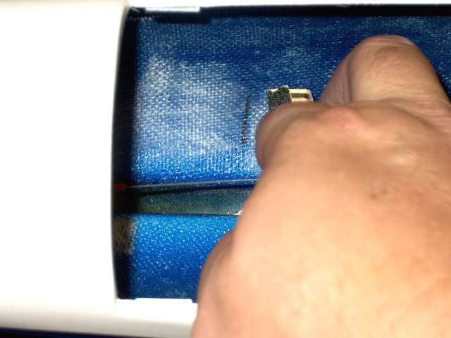
and installation. Remove the tabs from your servo and place it
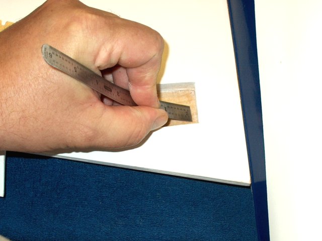
over each opening. Mark the outer shape and enlarge the
opening width | |
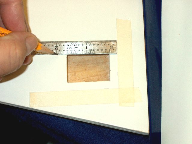
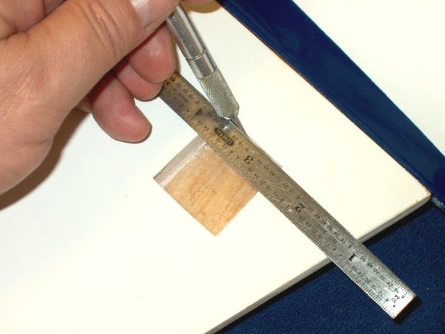
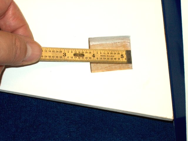
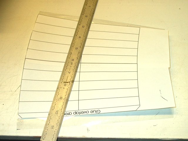
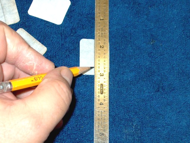
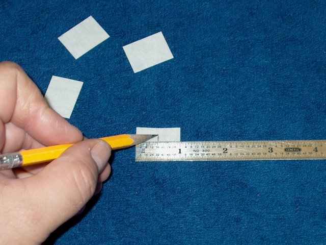
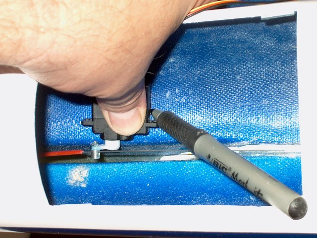
Measure the opening of the servo well and
add 1/4" overhang to each of the four sides
| |
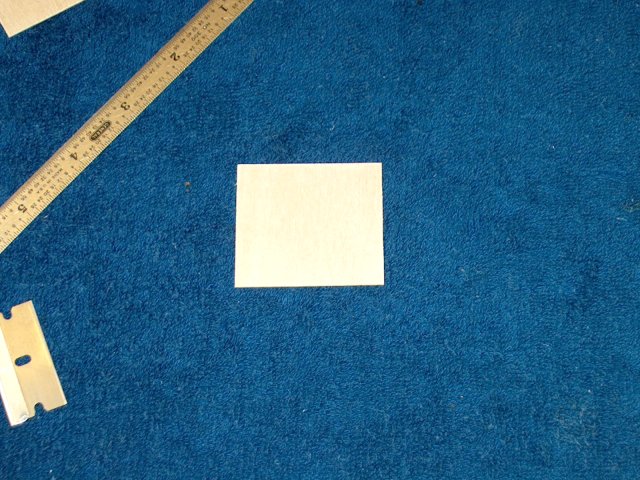
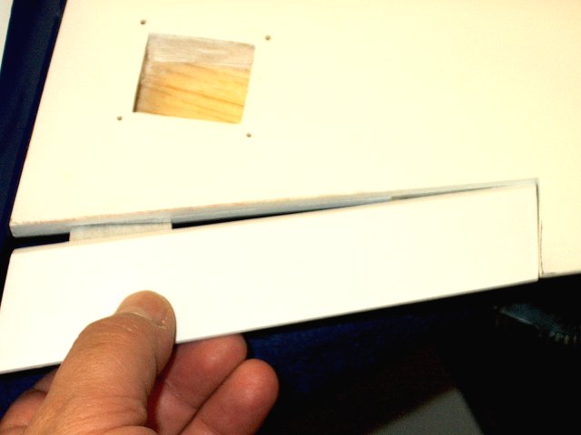
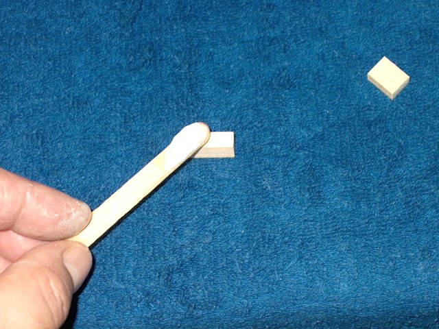
Make some servo hatches by cutting two
pieces of 1/32" ply to the dimensions you just measured
| |
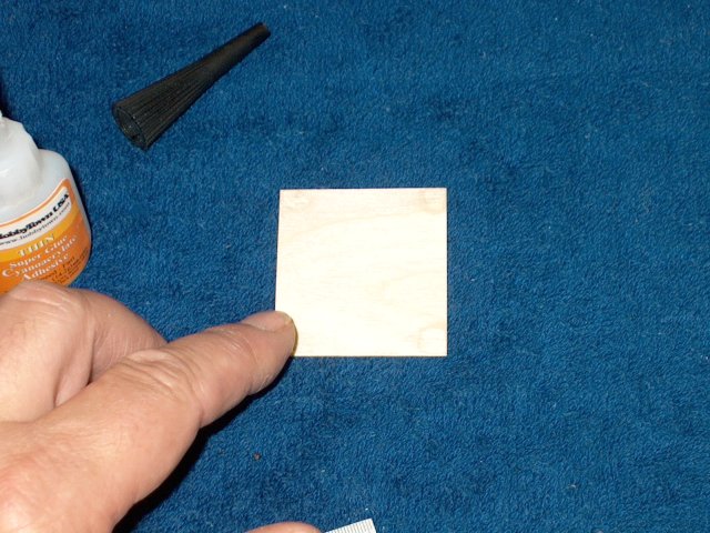
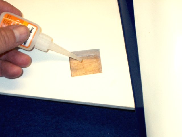
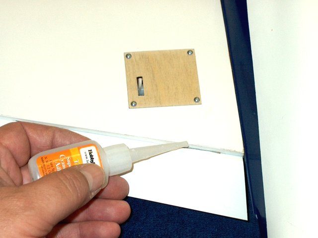
Apply a drop of thin CA to the bottom
corners of each hatch, then sand smooth once dried
| |
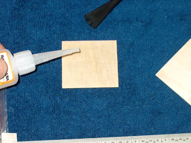
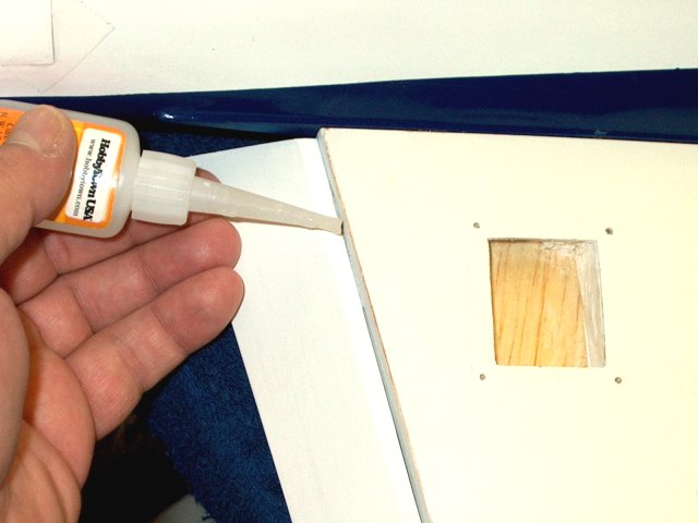
Apply CA to the top of each hatch and
allow it to soak in, then sand them to a plastic like finish
and paint if necessary | |
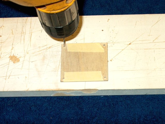
Stack both hatches and hold them together
with masking tape, then drill 1/16" holes at each corner,
about 1/8" in from the sides | |
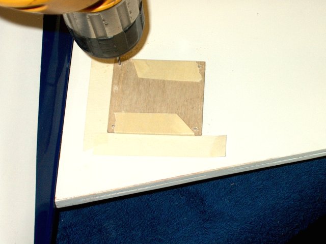
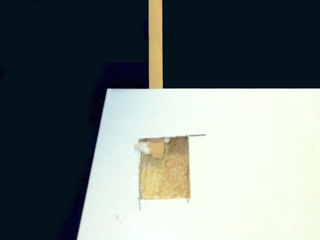
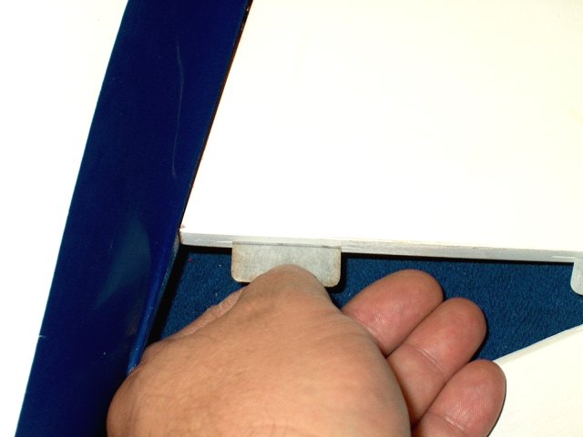
Use tape to mark the location where the
hatches must be placed so they overlap the opening about 1/4"
on each of the four sides. Drill 1/16" holes into the wing
using the previously drilled holes in the ply as guides
| |
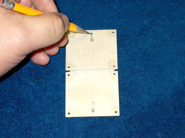
Mark on the inside one hatch for the left
and one for the right and also draw an arrow on each hatch to
show forward placement | |
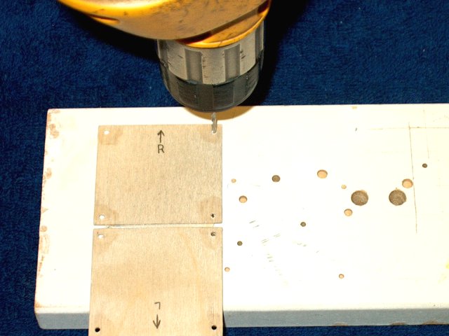
Open up the holes on both hatches with a
3/32" drill. Sand the surface of the holes smooth if
necessary | |
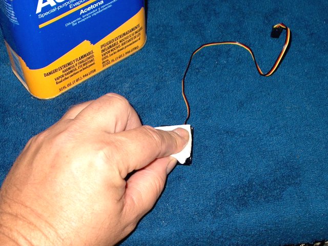
Clean the mounting surface of each wing
servo with Acetone. HS-81MG metal gear servos were used for
the Ailerons | |
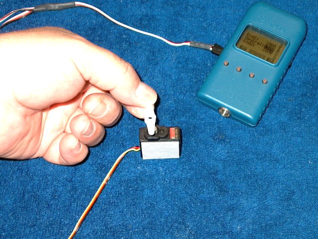
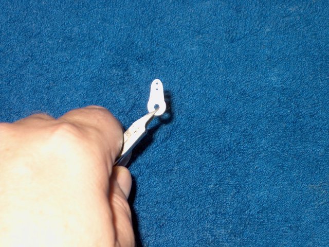
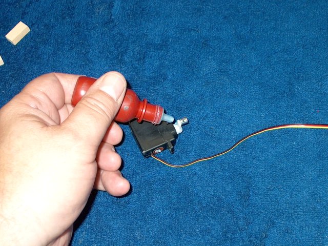
Connect each servo to a receiver or servo
tester and use a horn to make sure the servos are
centered | |
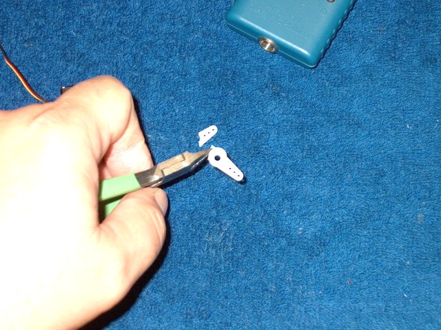
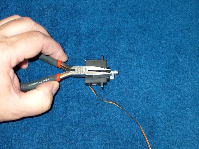
Remove each horn, then cut away the unused
side of each horn | |
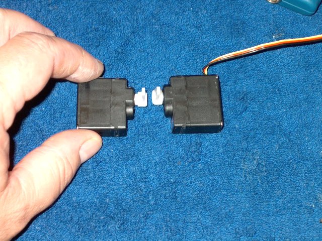
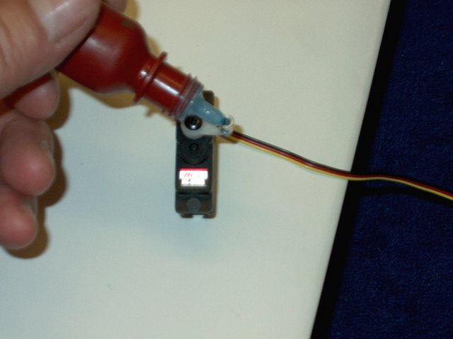
Install the horn on each servo and make a
left and a right assembly. Install each servo temporarily in
the wing and make sure the horn is centered and pointed
straight up. Even though the horns may be centered outside the
wing, the servos themselves wind up being tilted downward
toward the front of the wing, so you may have to move the horn
back toward the Aileron a notch for it to be centered in the
well. The servo horns need to be centered in the well or they
will not have full range of motion!
| |
Cut two pieces of servo tape and install
them on the respective bottoms of each servo. Install the horn
screw in each servo | |
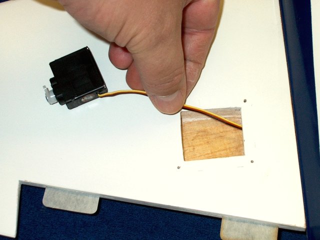
Run the servo wire for one wing through
the hole into the fuselage area | |
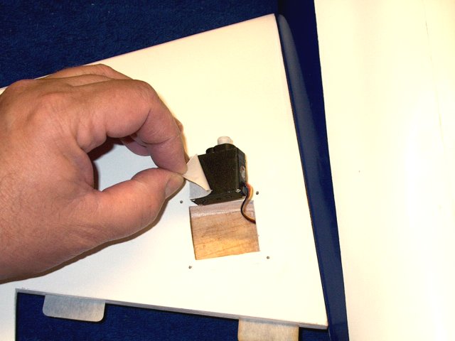
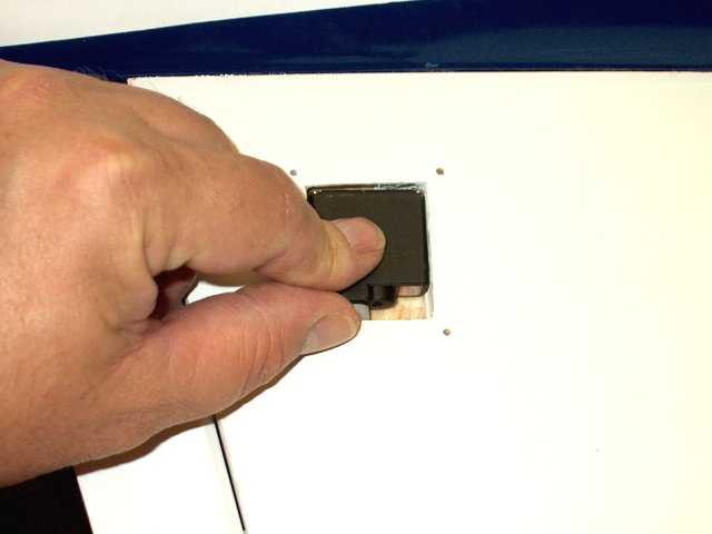
Remove the backing from the servo tape,
then install the servo in place, making sure the horn has
clearance and does not bind on the side of the well
opening | |
Position the hatch in place, then slide it
upward and mark a 3/16" slot on the hatch for a horn
opening | |
With the opening drawn, cut out the ply
and use a file and sandpaper to clean up the opening
| |
Position the hatch over its mounting holes
and check the fit of the horn, then sand as necessary. The
opening needs to be about 3/4" long
| |
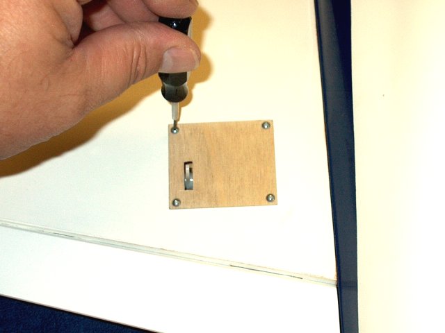
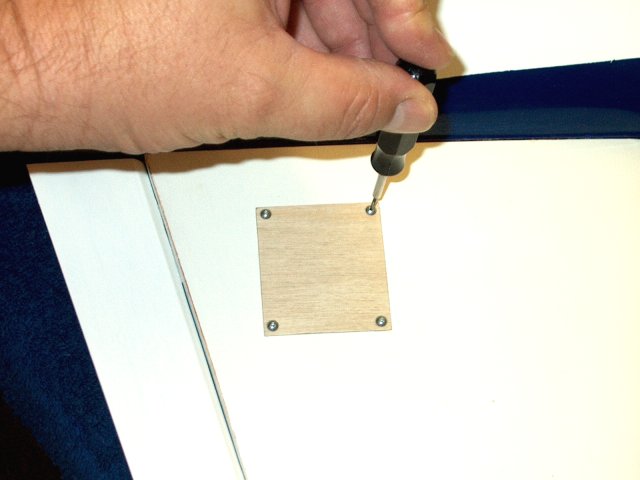
Install the hatch with some #2 button head
screws | |
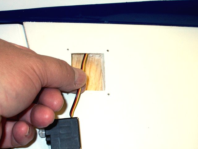
Run the other servo's wires through the
opening and into the fuselage | |
Remove the backing from the servo
tape | |
Install the servo in place, making sure
the horn has clearance and does not bind on the side of the
well opening | |
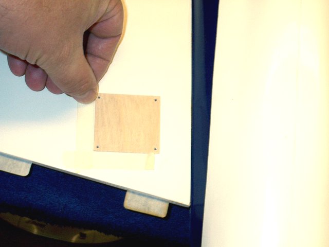
Install the hatch and cut out the slot in
the same way you did the first hatch
| |
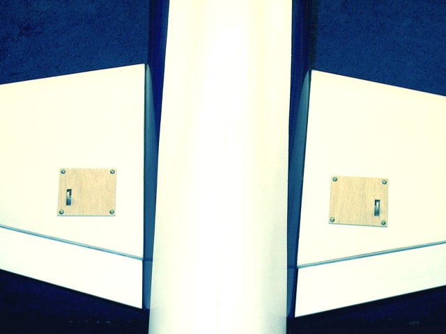
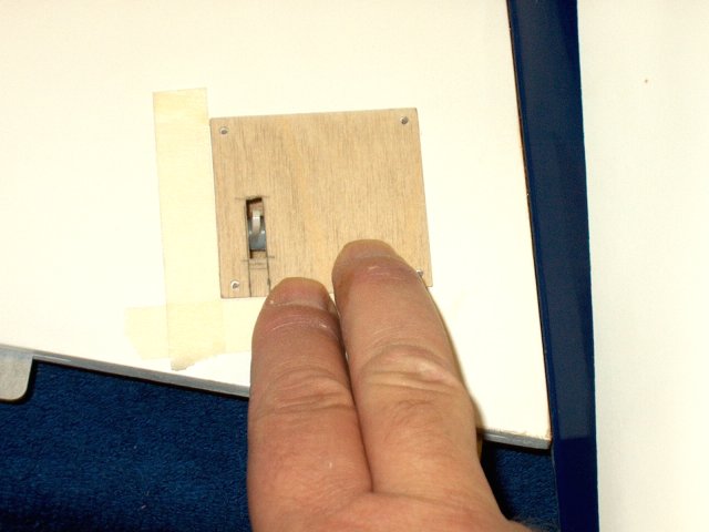
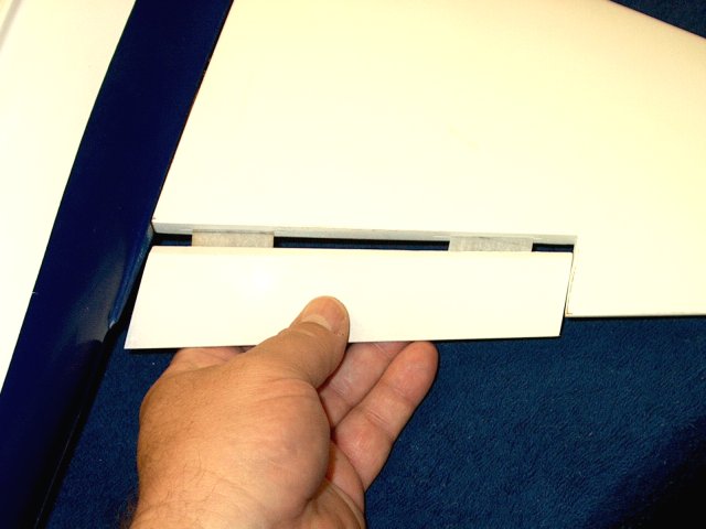
Install the second wing hatch and check
for horn clearance. Both hatches are shown installed
| |
Measure and mark the center on each of the
Aileron hinges | |
Draw a line down the center of each
hinge | |
Install each hing into the wing up to the
line. Open the slots with a razor if necessary and position
the hinges at least 1/2" in from each end
| |
Instal an Aileron, making sure there is
clearance on both ends. Make sure the hinges remain square in
the slots and are not pushed into the fuselage
| |
Tilt the Aileron downward so there is
enough deflection, then apply thin CA to each hinge from the
top and bottom. The CA should wick into the slots
| |
Install the second Aileron, making sure
there is clearance on both ends | |
Tilt the second Aileron downward so there
is enough deflection, then apply thin CA to each hinge from
the top and bottom. The CA should wick into the slots
| |
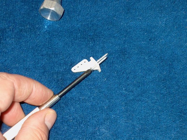
Install a clevis on each of the two
pushrods and center them on the threads
| |
Drill the Aileron servo horn out of
necessary so the clevis has a nice and tight fit
| |
Install the clevis on a servo horn
| |
Install the second clevis on the other
servo horn | |
Remove the tape from maufacturing that is
holding the hatch in place | |
Remove the bottom hatch
| |
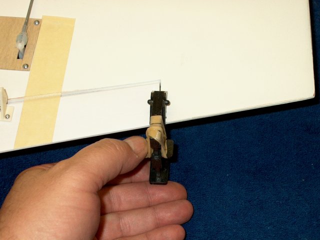
Use a piece of tape that is placed
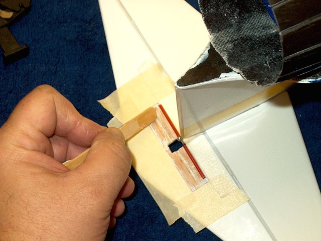
parallel to the servo and place the pushrod parallel to the
tape | |
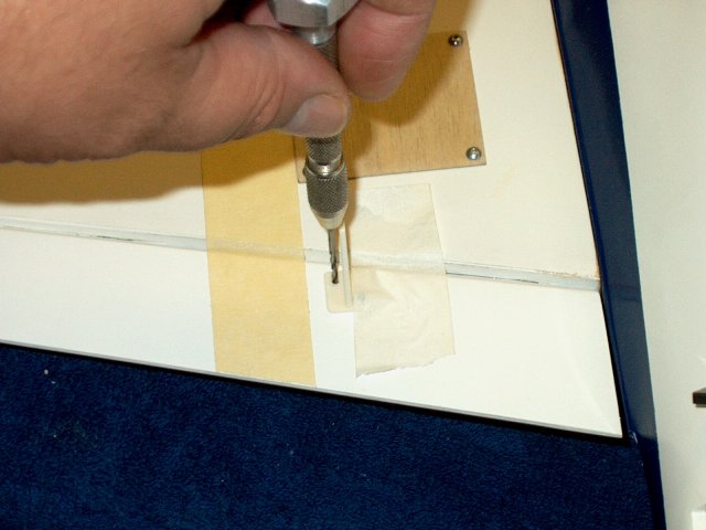
Install the horn as shown on the inside of
the wire. Use a drill to make a 3/32" hole
| |
Install a screw in the servo horn. It is a
good idea to pre-thread the servo horn caps by using a screw
to cut threads in each cap | |
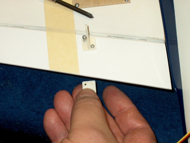
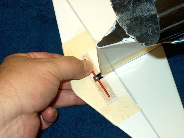
Install the horn in place as shown
| |
Use the pushrod to keep the horn straight,
then tack it in place with CA | |
Drill the second hole for the horn
screw | |
Install the second screw and check pushrod
alignment | |
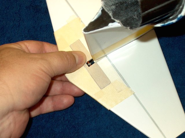
Install the cap that you pre-threaded in
place as shown. Do not overtighten the screws
| |
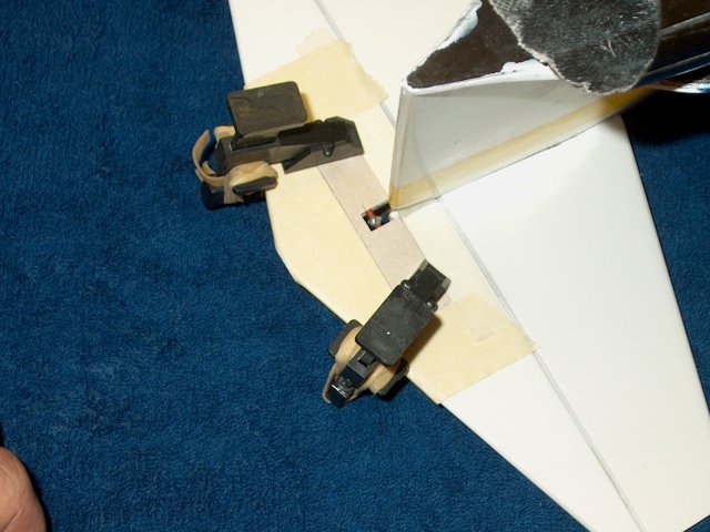
Use tape to align the second pushrod and
drill the holes for the second aileron horn
| |
Install the screws in the aileron
horn | |
Position and install the horn in the
Aileron and screw on the cap. Be careful not to
overtighten | |
Clamp the end of the Aileron so it is even
with the wing | |
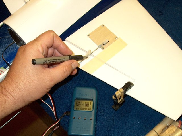
Connect a servo to a receiver or servo
tester, then center the servo | |
Mark the location of the Aileron horn hole
on the pushrod | |
Begin making a Z-Bend at the mark
| |
Finish the Z-Bend and trim off the excess
pushrod. Clean up the end tip with a grinder
| |
Open up the Aileron horn with a drill so
the pushrod will fit | |
Install a pushrod on the Aileron
horn | |
Clip the clevis in place on the servo
horn. A piece of fuel tubing is used as a safety retainer on
the clevis | |
Clamp the end of the second Aileron so it
is even with the wing | |
Connect a servo to a receiver or servo
tester, center the servo, then mark the location of the
Aileron horn hole on the pushrod | |
Make another Z-Bend at the end of the
pushrod as you did with the first Aileron
| |
Drill the Aileron horn and fit the
pushrod, then clip the clevis to the second servo horn.
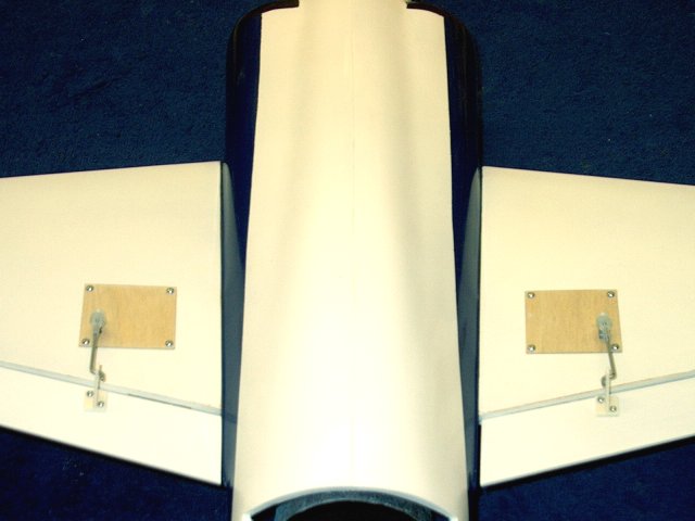
Completed Aileron installation is shown
| |
Use a grinder to carefully cut the
remaining screw threads flush to the plastic cap Do not
overheat by cutting to hard or you can deform the cap. Do a
little and allow the screw to cool | |
Apply some thick CA to the top of the
threads to prevent snagging or cutting
| |
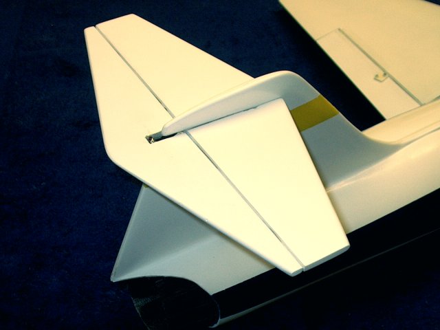
Mark center lines down each of the four
Elevator hinges | |
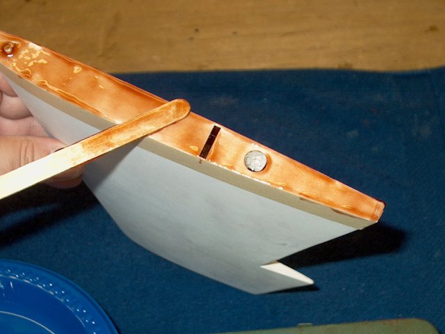
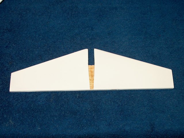
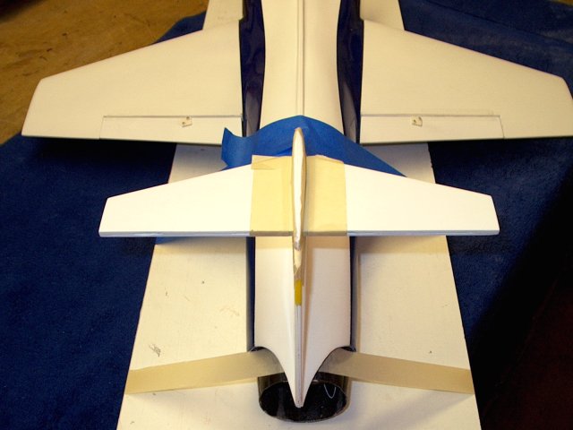
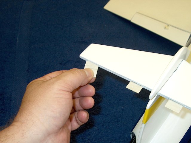
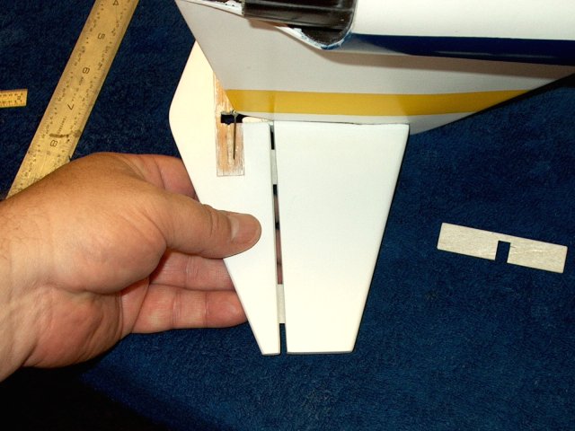
Install the Horizontal Stab in the slot
from the rear until it is flush with the vertical stab
joint | |
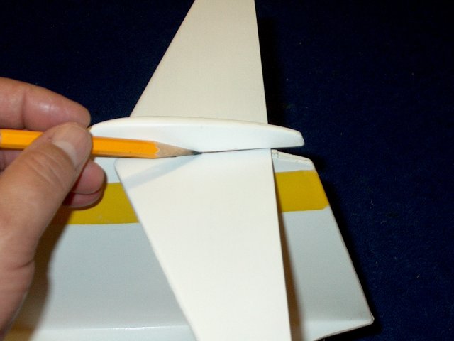
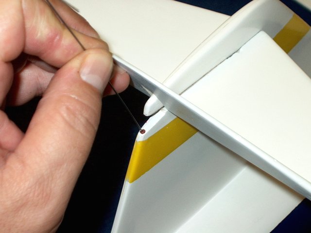
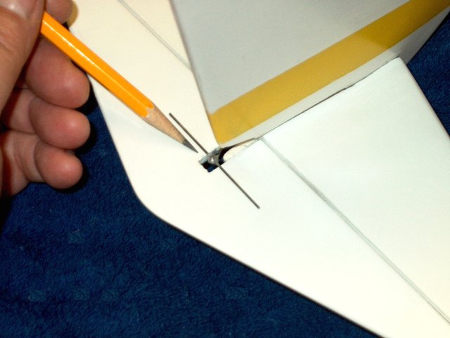
IMPORTANT: Make sure the Stab is
perpendicular to the vertical stab before proceding. Use a
pencil to mark the stab and fuselage at all points where they
join and mark both the top and bottom sides
| |
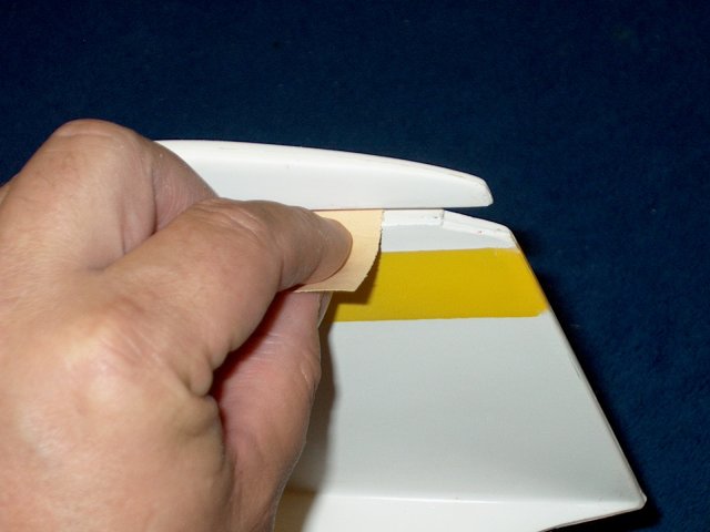
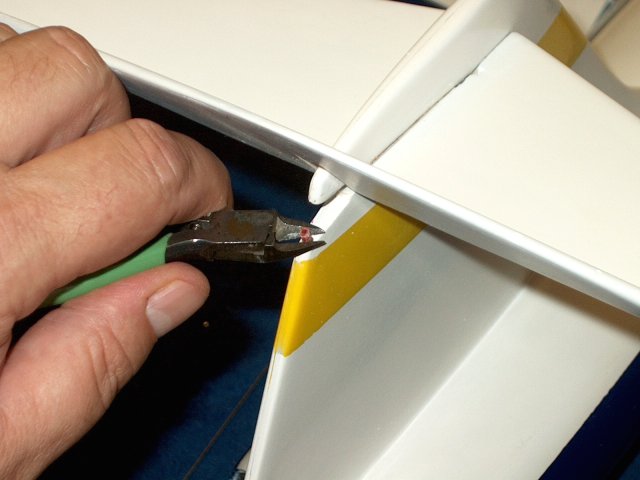
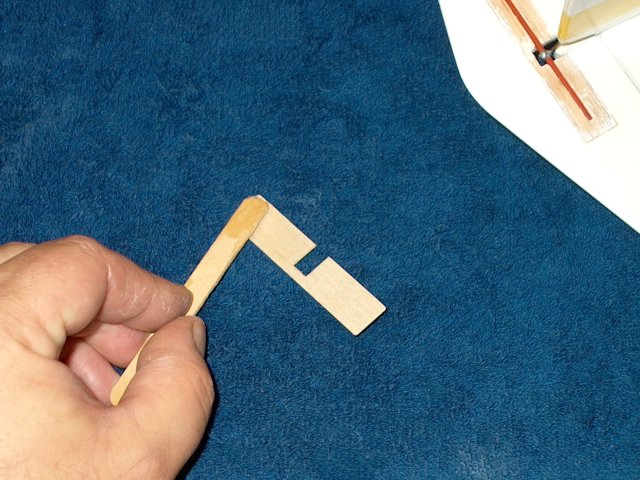
Remove the stab and cut just inside the
pencil mark to remove the excess covering material. Do this to
both the top and bottom | |
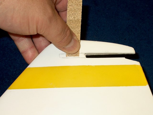
Lightly sand inside the pencil marks on
the vertical stab where the horizontal stab will reside for a
good glue purchase | |
Rough up the top and bottom of the
vertical stab slot, taking care not to change the shape of the
slots | |
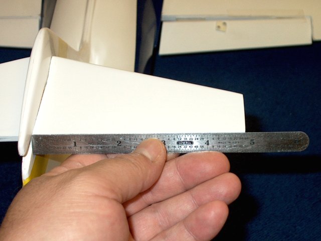
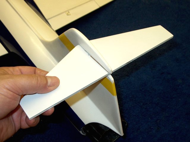
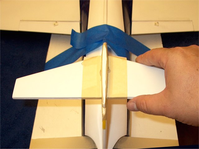
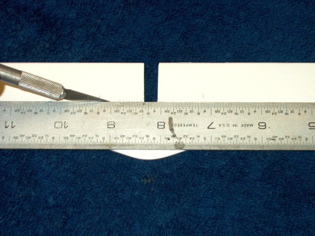
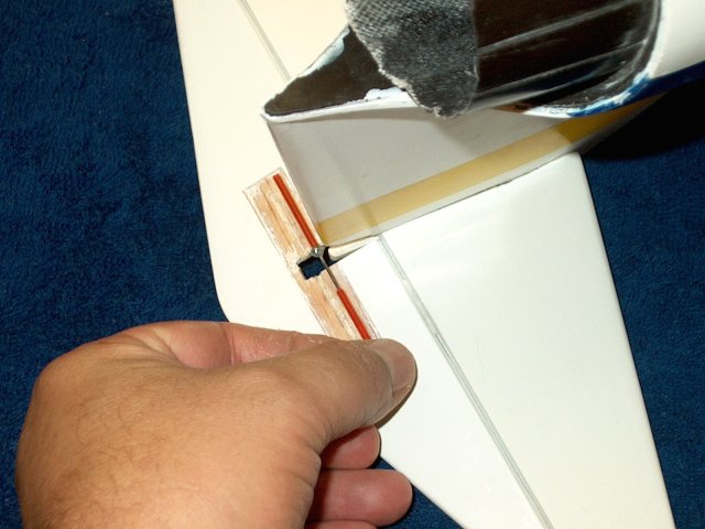
Install the horsizontal stab and measure
at the rear both sides to insure it is centered
| |
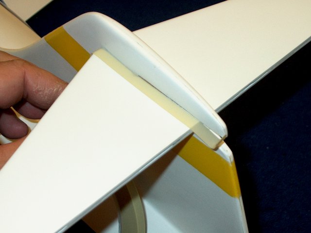
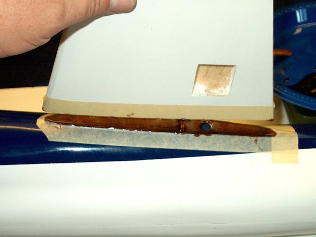
Tape the stab even to the joint to catch
excess epoxy | |
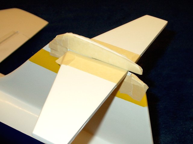
Finish by taping the vertical stab above
and below the horizintal as shown | |
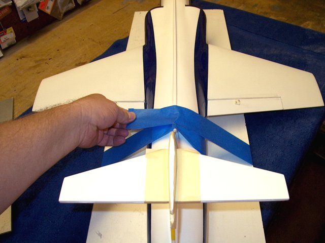
Place the model on a flat surface and use
tape to hold the center in pace | |
Run masking tape over the exhaust tube and
slightly forward, then pull tight so the pivots back and the
rear is flush with the surface | |
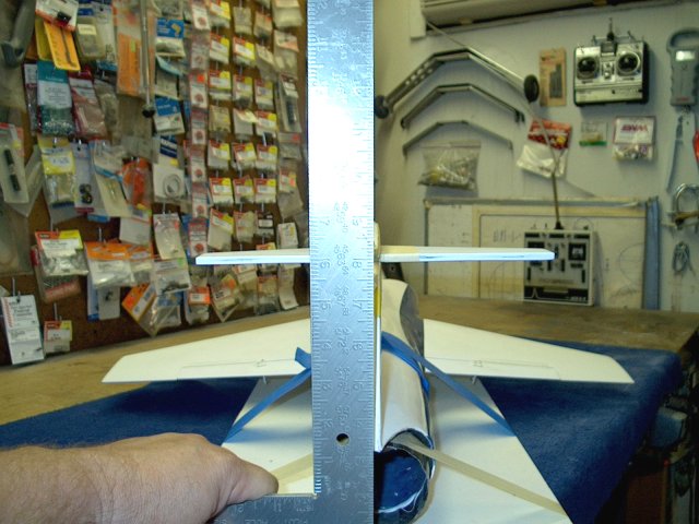
Use a square to rotate the model and
adjust the vertical stab so it is perpendicular to the
surface | |
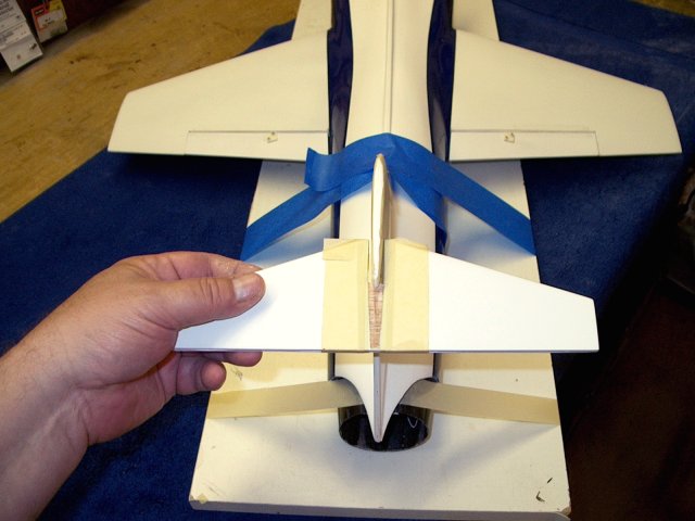
Remove the horizontal stab
| |
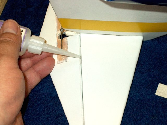
Use 15 minute epoxy so you have enough
time to adjust and apply epoxy to the top and bottom of the
vertical stab slot, as well as the forward sides of the
stab | |
Apply epoxy to the horizontal stab on the
forward slot and rear exposed surfaces
| |
Install the horzintal stab on the
fuselage | |
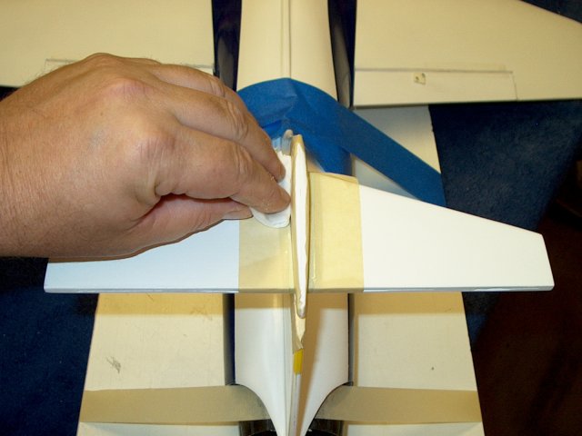
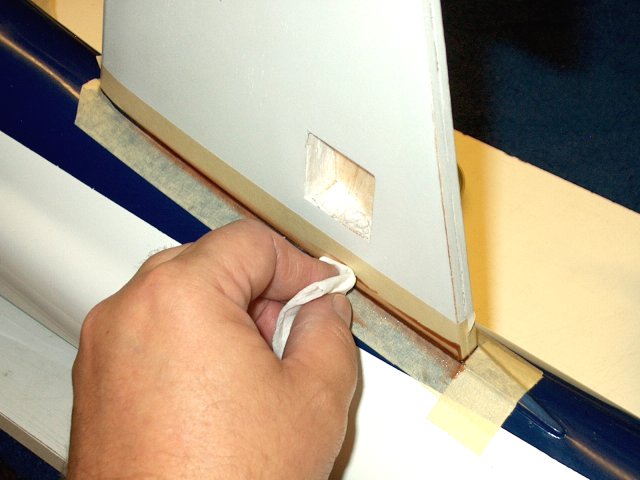
Clean any excess epoxy with paper towels
and alcohol | |
Insure the rear of the stab is centered
and the same distance from the vertical stab on both
sides | |
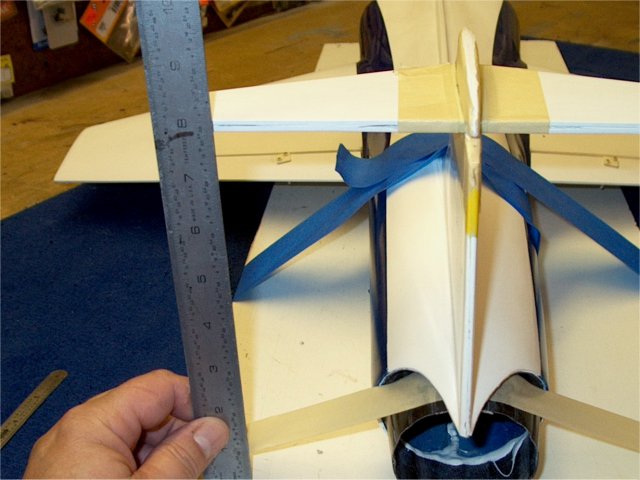
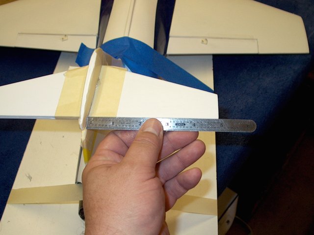
Use a ruler and make sure the horizontal
stab is parallel. Adjust if necessary before the epoxy
sets | |
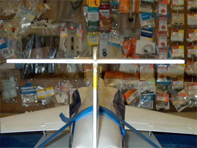
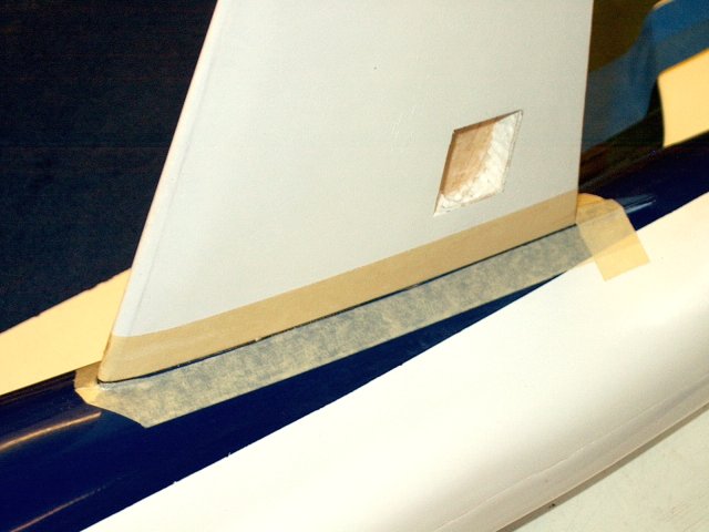
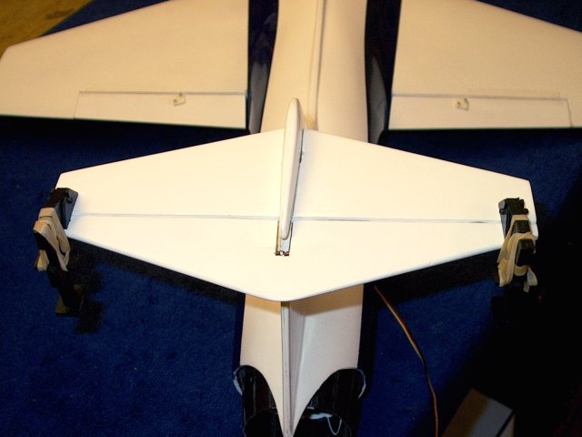
Horizontal stab sown installed
| |
Install the hinges in the horizontal stab
up to the center line | |
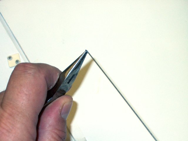
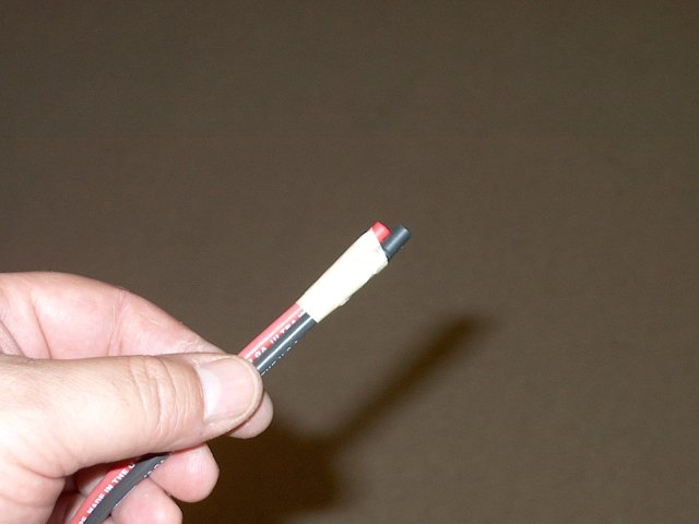
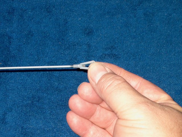
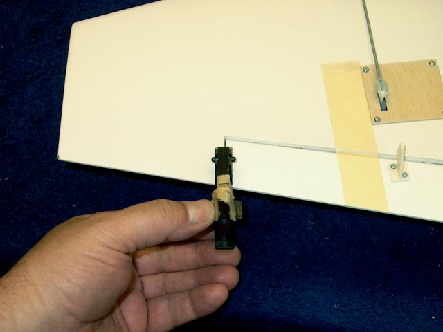
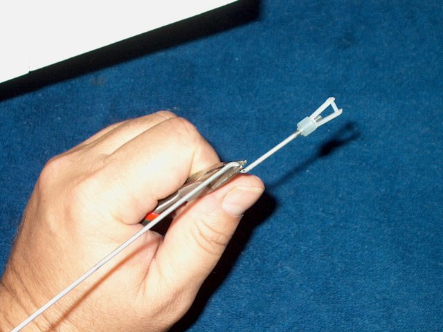
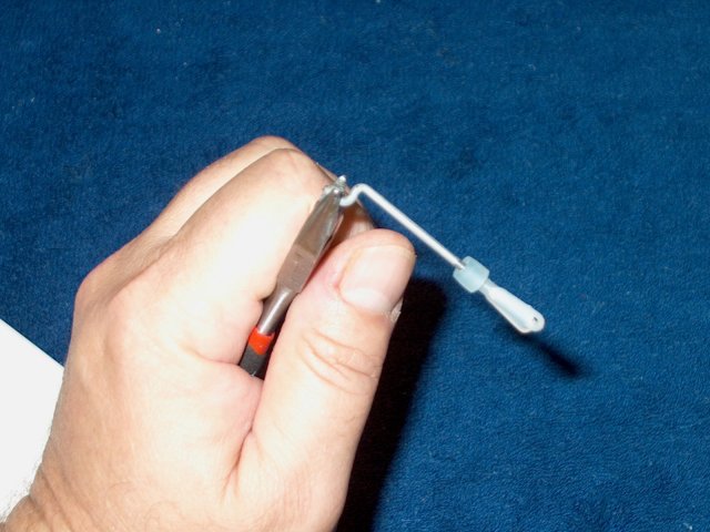
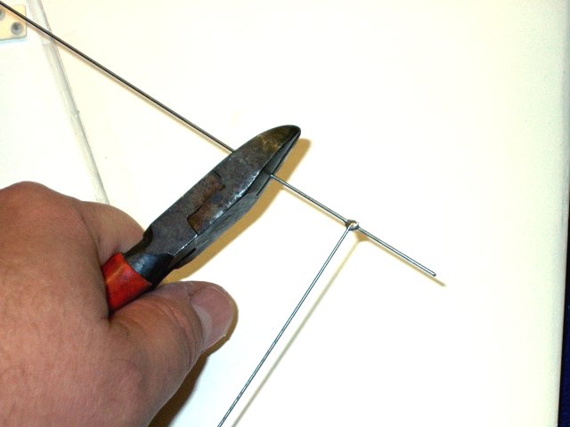
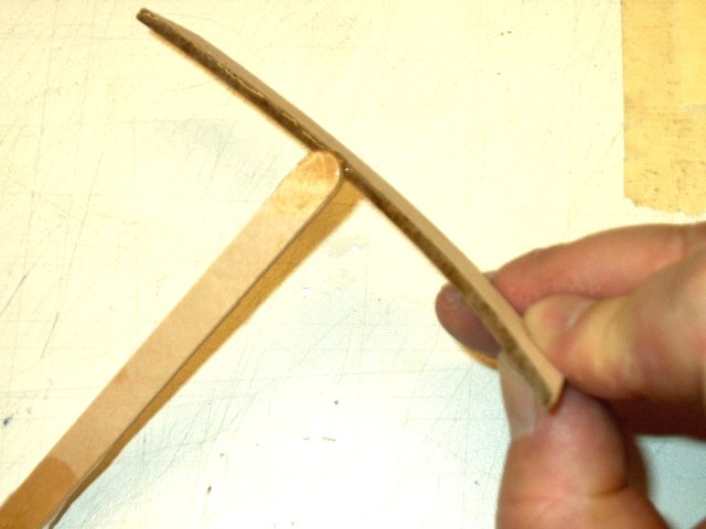
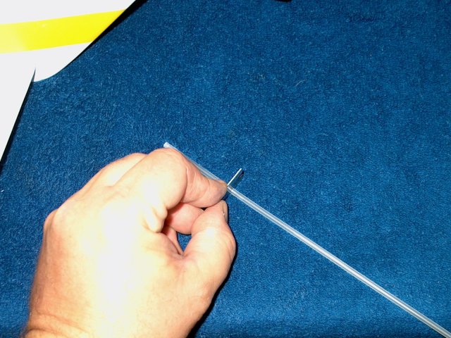
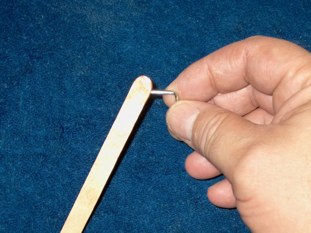
Cut off the Z-Bend on the pushrod wire,
then make a very small loop and a half with needle nose
pliers | |
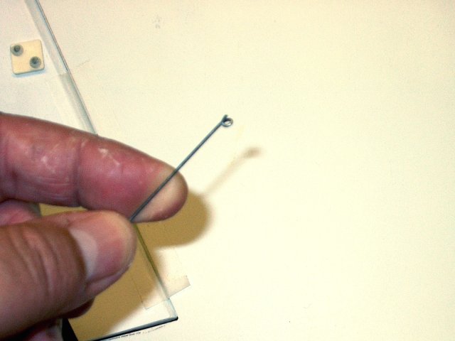
Loop shown, which should be just round
enough for the wire to pass through
| |
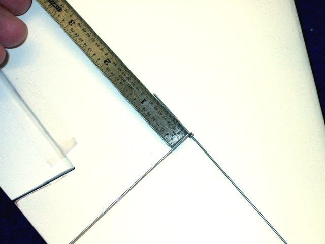
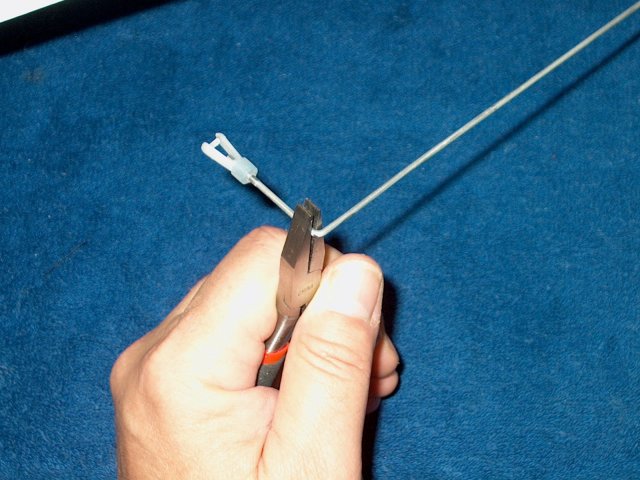
Cut a 2 1/2" piece of wire from the other
end and install it in the loop so that 1" protrudes from a
side | |
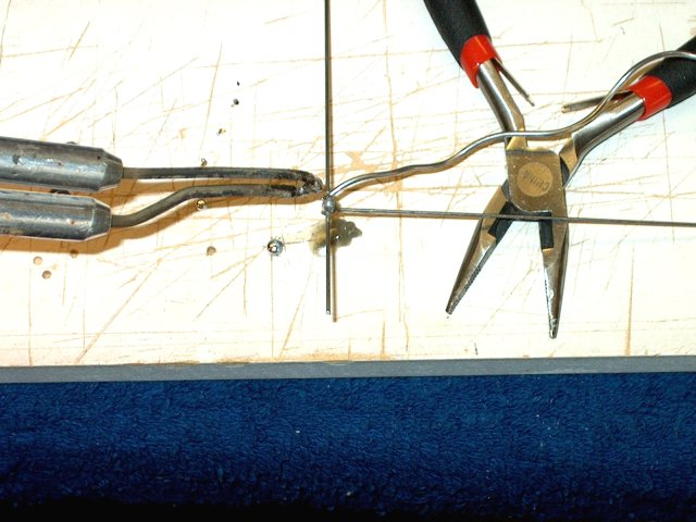
Use soldering flux, good solder such as
Deans and a high power gun and solder the joint. Make sure the
short wire remains perpendicular to the long wire before the
solder hardens | |
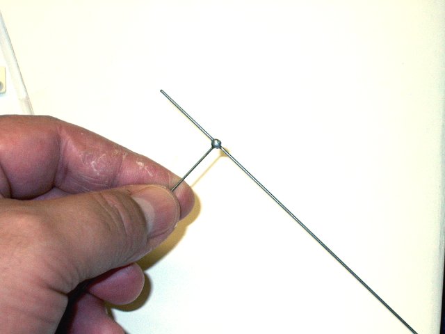
Solder joint shown completed
| |
Trim the other end so the you have 1" of
rod on each side of the joint | |

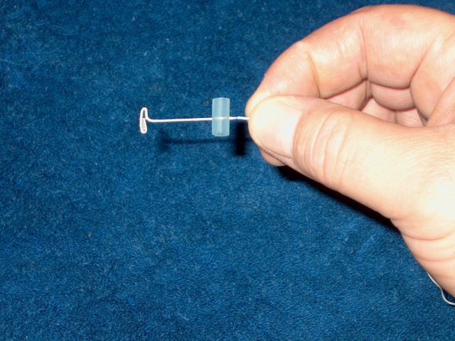
Cut two 1" pieces of plastic sleve from
the pushrod assembly and install them over the wires as
shown | |
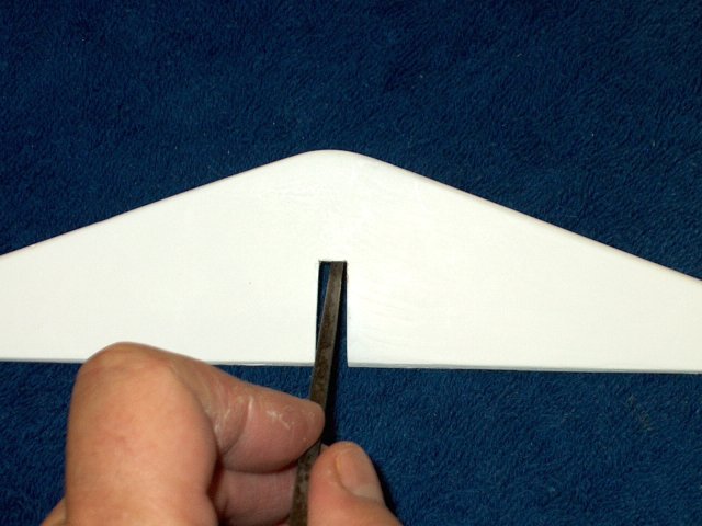
Box cut and file the rear of the fuselage
so it is square | |
Mark the top rear of the vertical stab
with a punch | |
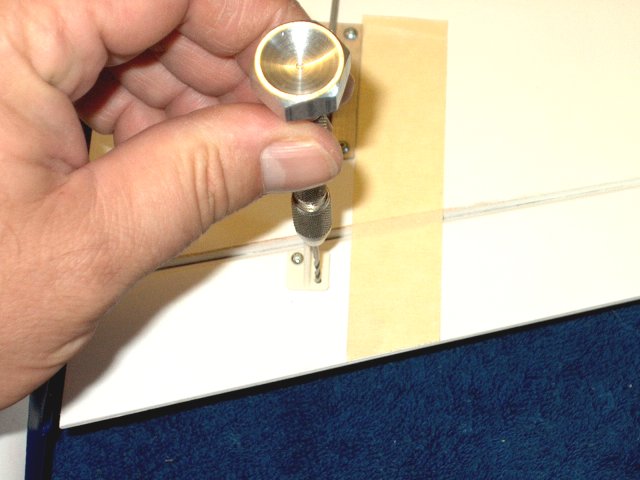
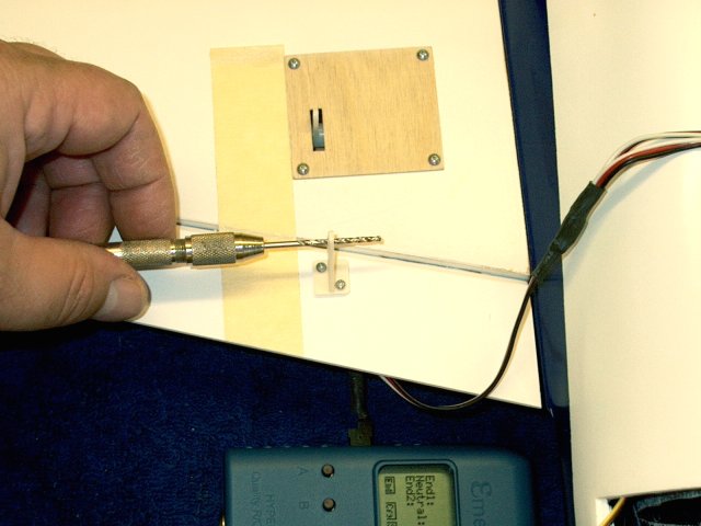
Use a 1/16" drill to open a small hole at
the marked location | |
Open the hole with a 3/32" drill
| |
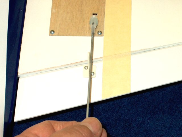
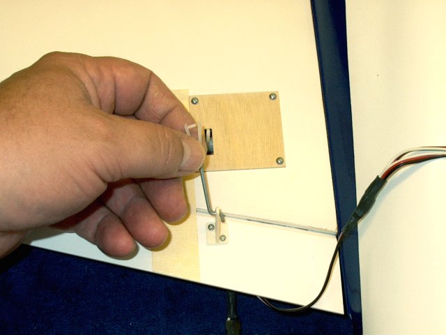
Install the pushrod sleeve
| |
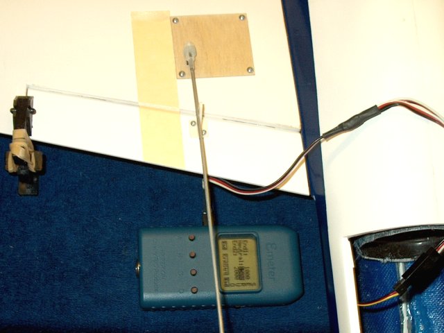
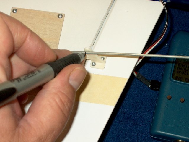
Install the pushrod and test for
binding | |
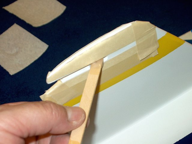
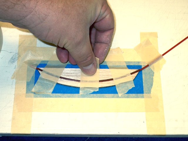
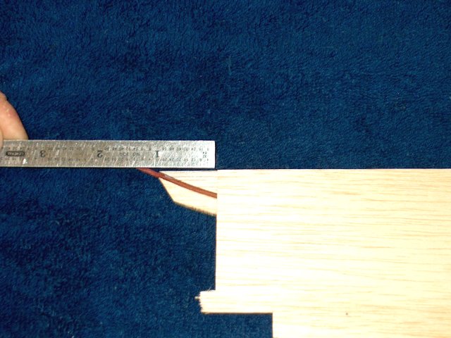
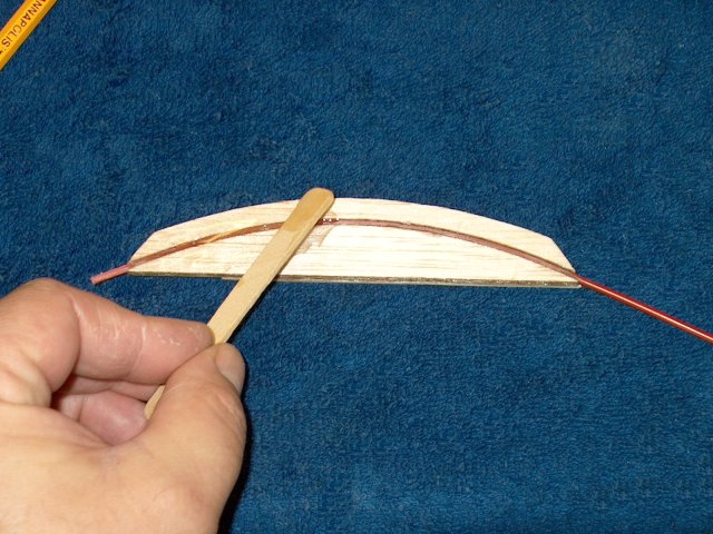
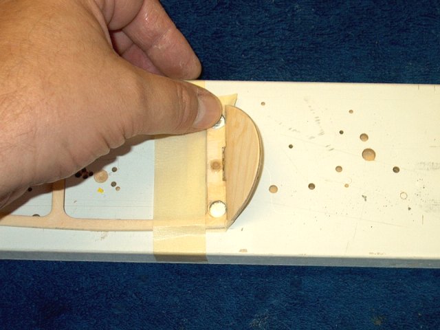
Place the pushrod sleeve across the
rounded mount plate. Leave about a 1/4" overhang on one side
and make a mark on the sleeve where it meets the other end of
the balsa mount | |
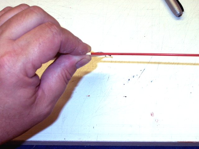
Sand the sleeve with 60 grit sandpaper
just enough to score it for good glue purchase. Sand from the
mark to the 1/4" overhang | |
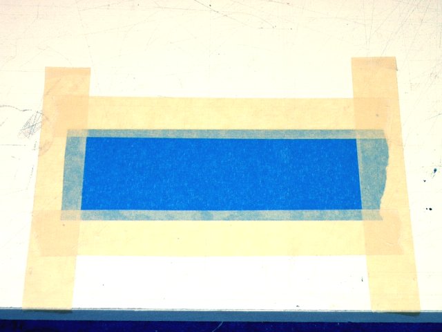
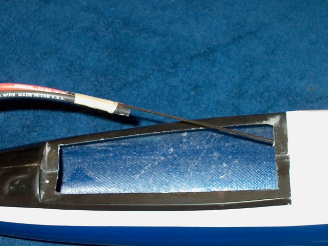
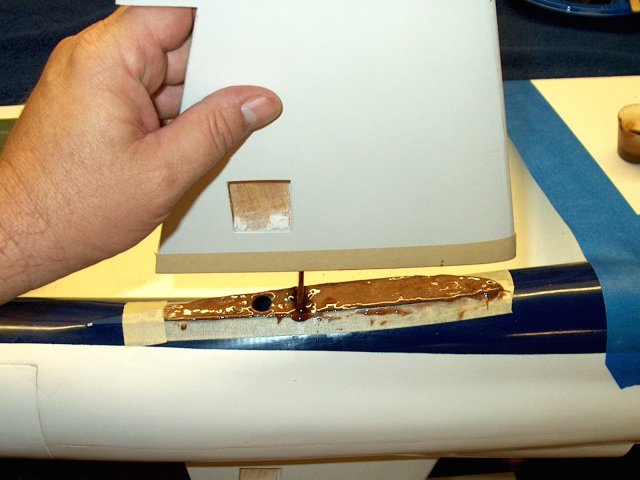
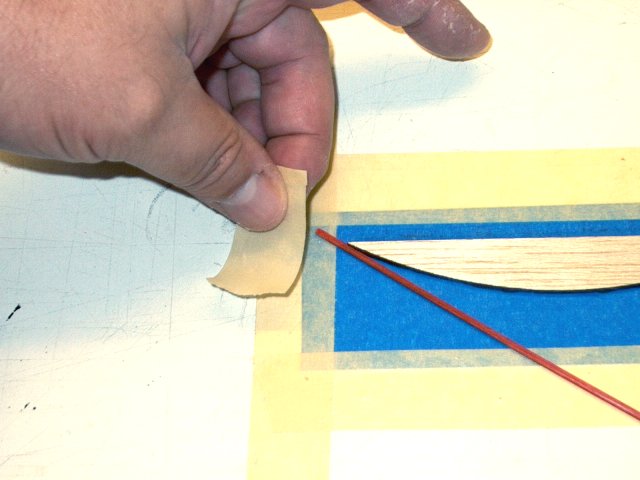
Install a piece of tape, as shown in blue,
sticky side up and about 6" wide | |
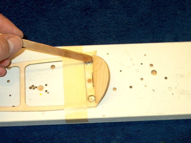
Apply epoxy to the rounded edge of the
mount | |
Place the mount piece on the tape as
shown | |
Apply epoxy to the curved edge of the
outer mount balsa plate | |
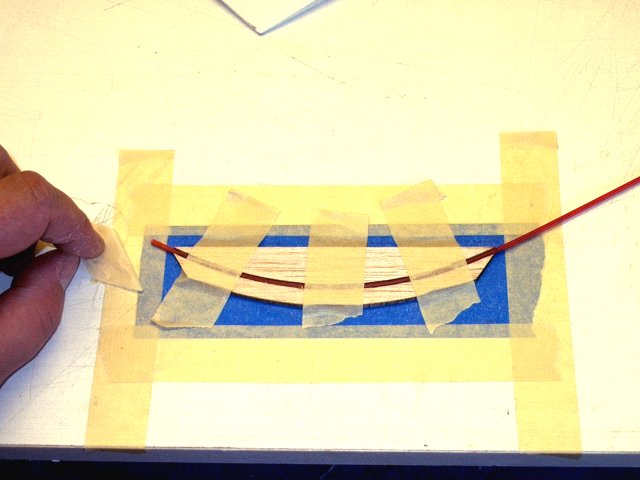
Starting at one end, leave 1/4" or so of
sleeve extending past the mount as shown on the left and use
masking tape to anchor it in place | |
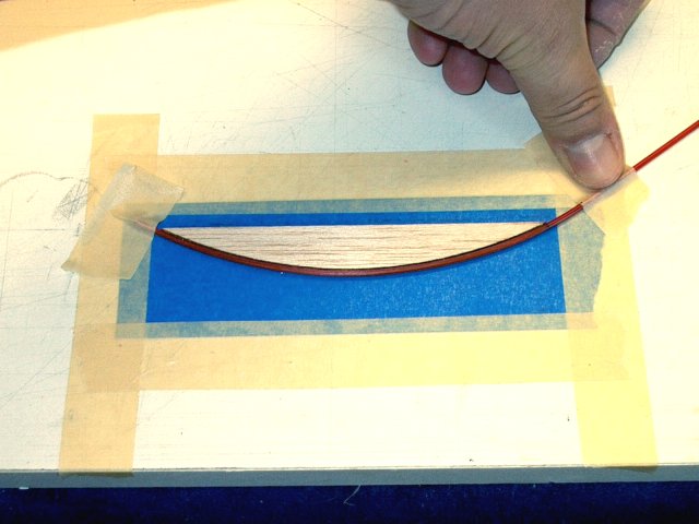
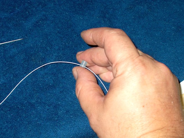
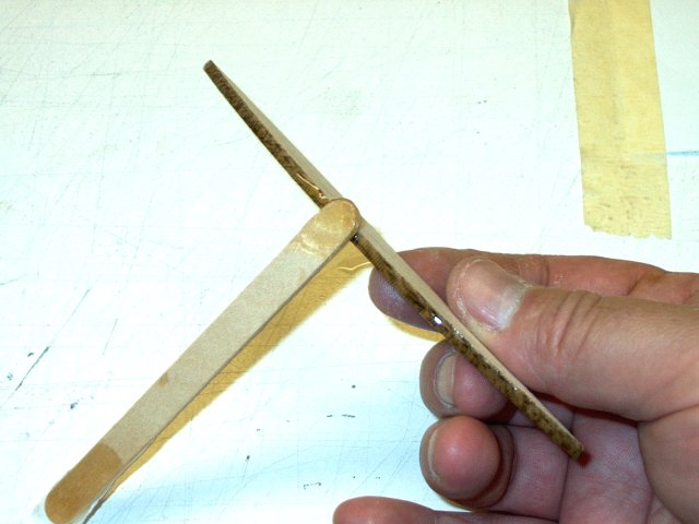
Bend the sleeve around the curve
| |
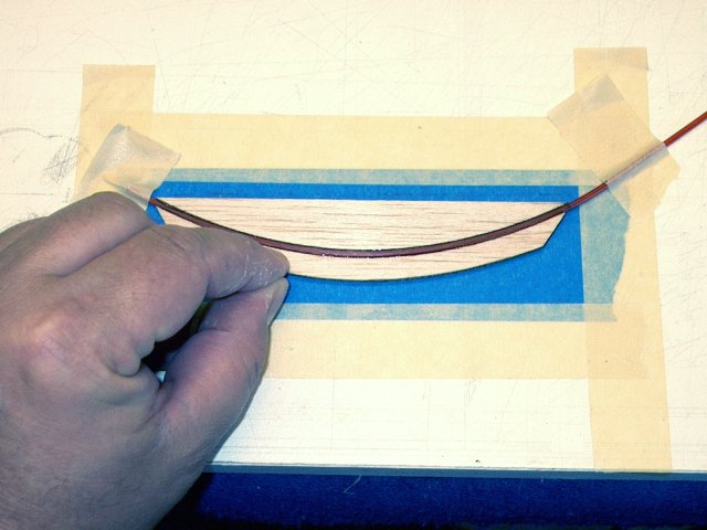
Install the outer mount in place, making
sure the sleeve is tightly wedged between both plates. Make
sure the ends of the plates are aligned with eachother
| |
Tape the sleeve down as shown and allow
the epoxy to set. You can also cover the assembly with a
plastic sheet and block of wood to weight it down and keep it
flat | |
Once the epoxy sets, remove the tape from
the assembly | |
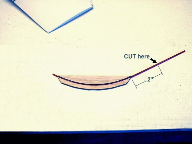
Trim the long side of the plastic sleeve
2" past the balsa mount as shown | |
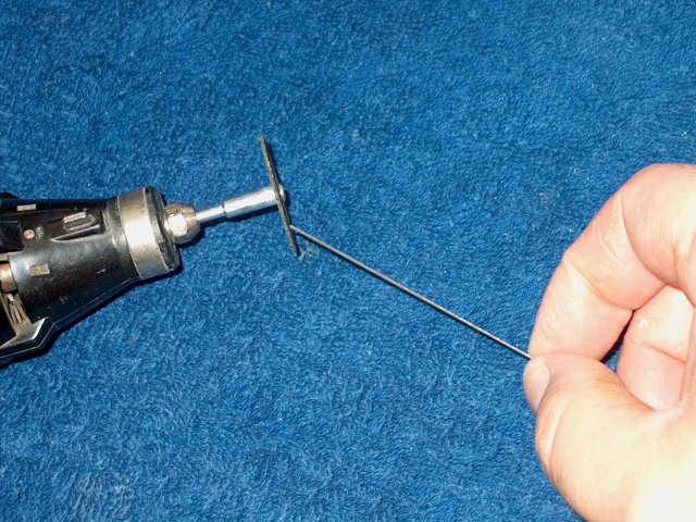
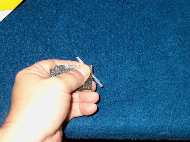
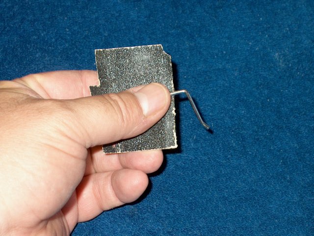
Grind the other end of the pushrod to a
rounded shape so it doesn't bind when installed inside the
sleeve | |
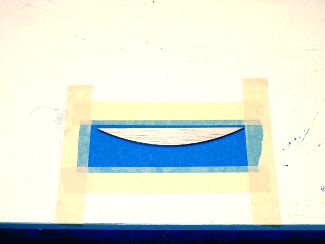
Place a scrap piece of 3/32" balsa over
the mount, leaving 1" of open area at the short end as
shown | |
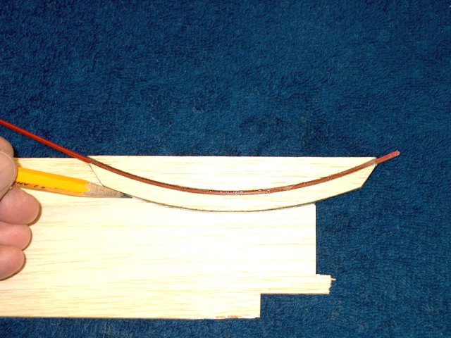
Draw and cut out the balsa cover
| |
Sand the mount cover even with the
mount | |
Apply epoxy to the entire side of the
mount as shown. Make sure you apply epoxy to the correct
side | |
Apply a thin coat of epoxy to the
cover | |
Install the cover on the mount
| |
Clamp the assembly together until the
epoxy sets | |
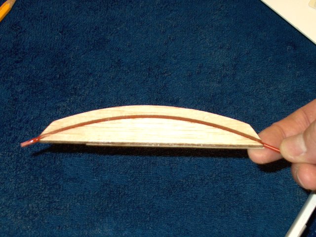
Pushrod mount assembly shown
completed | |
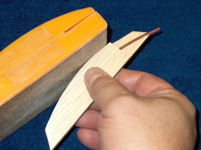
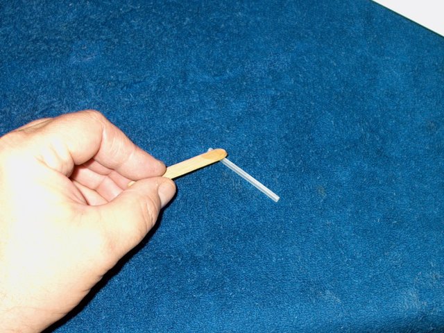
Slightly bevel the outer flat area so it
tapers toward the short end of the sleeve. Test fit it in the
inside of the vertical stab and taper until you hae a good
fit | |
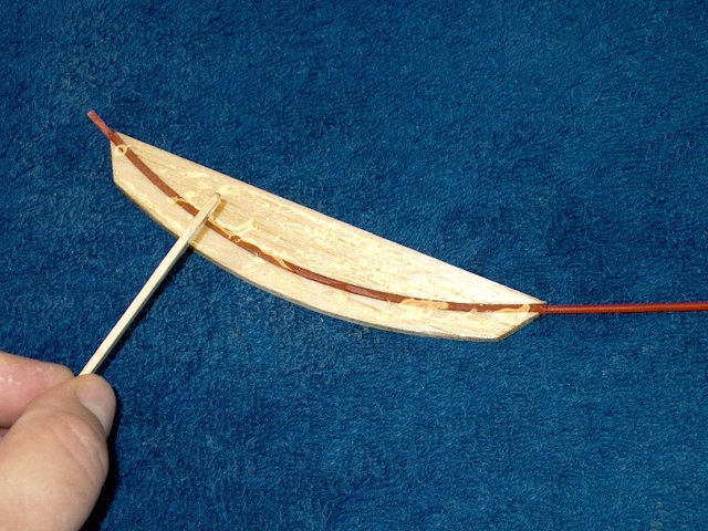
Apply a thick layer of epoxy to the sleeve
side of the mount | |
Make sure the entire mount is covered.
Install short end first and make sure the 1/4" of sleeve exits
the hole in the top of the vertical stab. It is ok if not all
the 1/4" exits | |
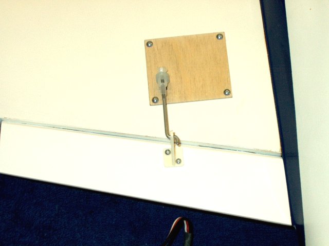
Install the plate to the side of the
vertical stab as shown. The end of the plate should be
recessed about 1/8" inside the stab opening
| |
Trim the pushrod sleeve flush to the top
of the vertical stab | |
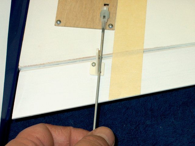
Install the pushrod in the sleeve
| |
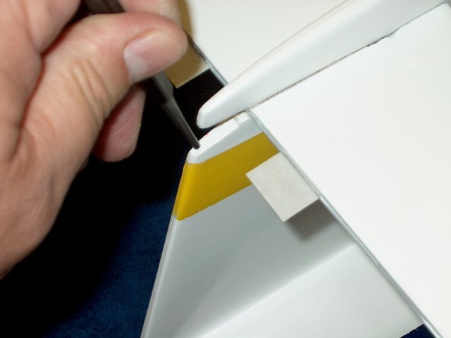
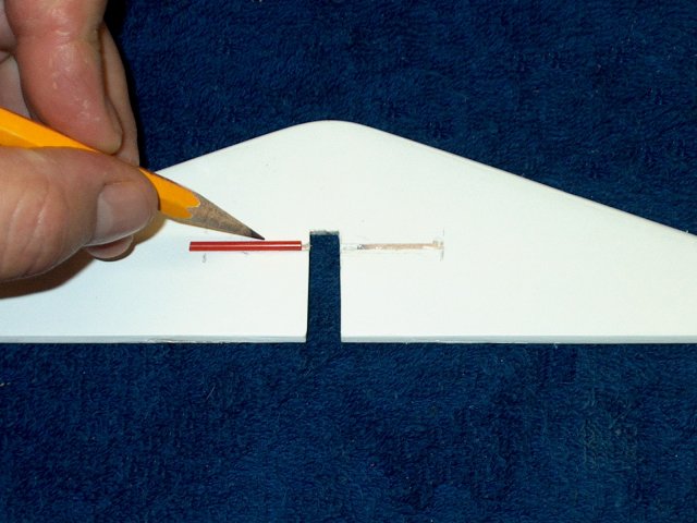
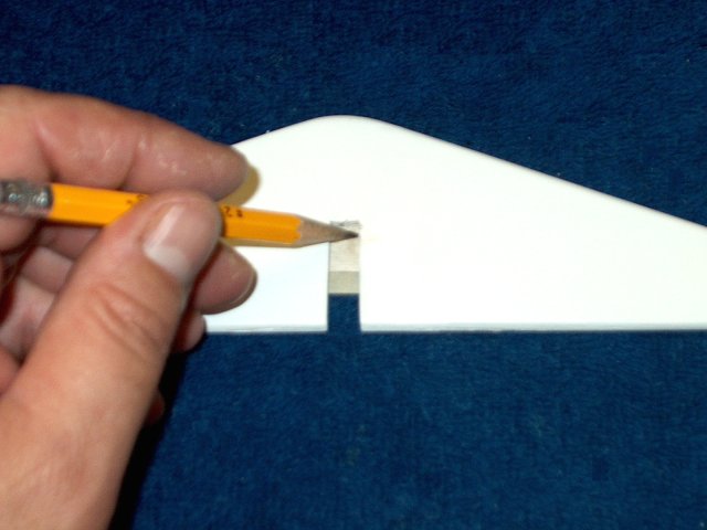
Install the Elevator and while keeping the
pushrod parallel to the stab, trace the outline of the
pushrod | |
Use a knife to remove the covering for the
pushrod. Re-install the elevator to make sure the cut is
centered | |
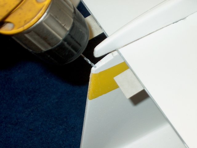
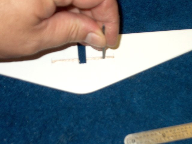
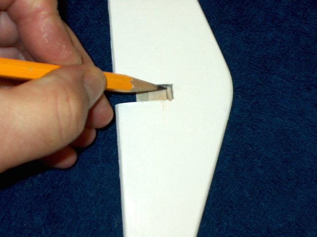
Center a pushrod sleeve over the removed
covering and draw an outline of the sleeve on each side. Cut
the drawn slot area halfway down into the stab. DO NOT CUT all
the way through to the other side (top of the stab)
| |
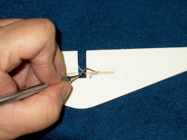
Use a pick or tool to remove the balsa
from each slot as shown | |
Make sure the slot depth is even all the
way across each slot. A 3/32" drill makes a good tool for this
and be sure to make the slot deep enough to completely recess
the sleeves | |
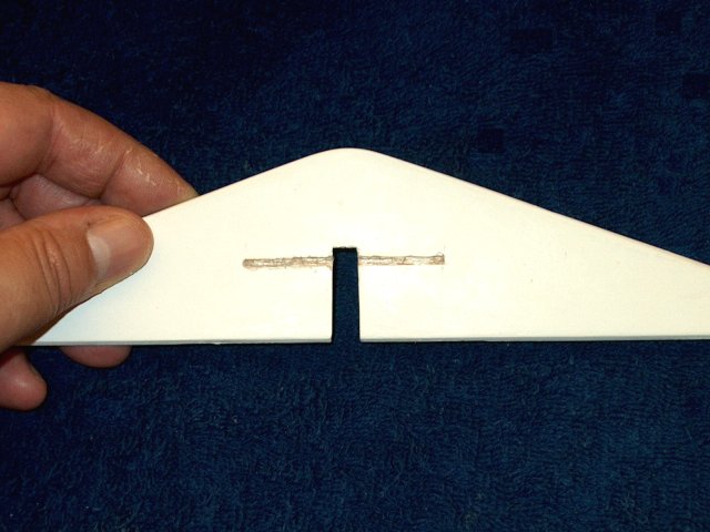
Slots are shown completed
| |
Measure and remove the covering about 1/4"
away from the slot on each side, as well as the ends
| |
Covering shown removed
| |
Cut a piece of 1/64" or 1/32" ply plate to
cover the opening | |
Tape the plate temporarily in place
| |
Turn the elevator over and draw the slot
opening on the ply plate | |
Draw the back of the slot at the
rear | |
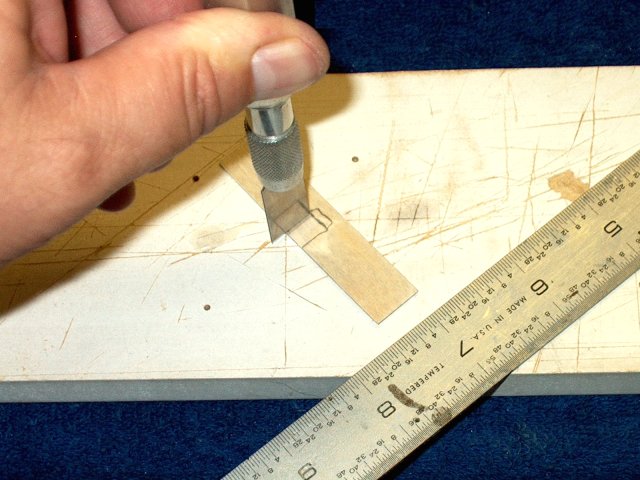
Remove the plate and use a tool or knife
to cut out the slot | |
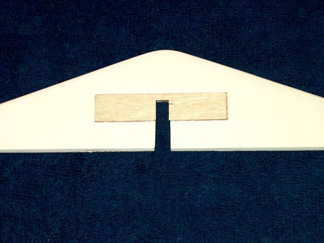
Install the plate and sand even with the
slot opening | |
Install the Elevator to the stab
| |
Flex the Elevator downward at lease 15mm
and use thin CA to glue the Elevator in place. Be sure to glue
from both the top and bottom | |
Install the poshrod sleeves on the
poshrod | |
Apply a thin layer of epoxy to the ply
plate. Make sure you apply epoxy to the correct side
| |
Tape off the edges of the plate area and
apply epoxy to the slots | |
Press the pushrod sleeves into the slots
as shown | |
Install the ply plate and clean up any
excess epoxy with alcohol | |
Clamp the plate in place until the epoxy
sets | |
Elevator installation completed
| |
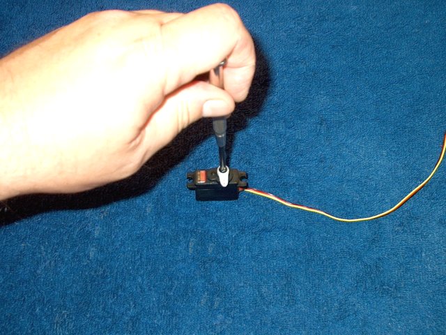
Trim a horn for your servo so that one arm
and two holes are showing | |
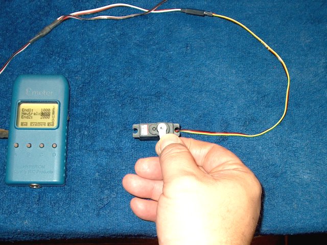
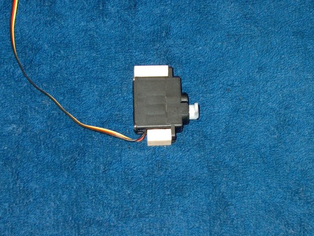
Center the servo, using a servo tester or
receiver | |
Install the arm as shown, centered on the
servo | |
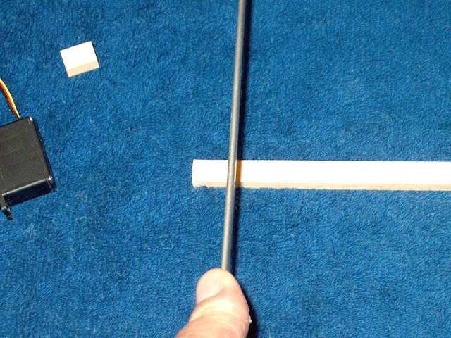
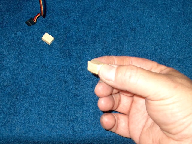
Use some scrap 1/4" x 3/8" pieces of
hardwood and cut them to fit the sides of the servo
| |
Hardwood shown cut to size
| |
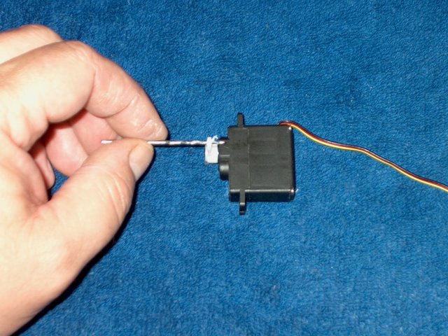
Drill the horn hole with a 1/16"
bit | |
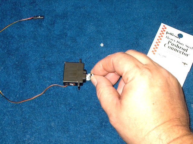
Install a Sullivan #550 pushrod connector
in the horn | |
Apply Loktite to the connector
threads | |
Install the nut snug, but loose enough for
the connector to spin. Apply a drop of CA to the threads to
hold the nut in place | |
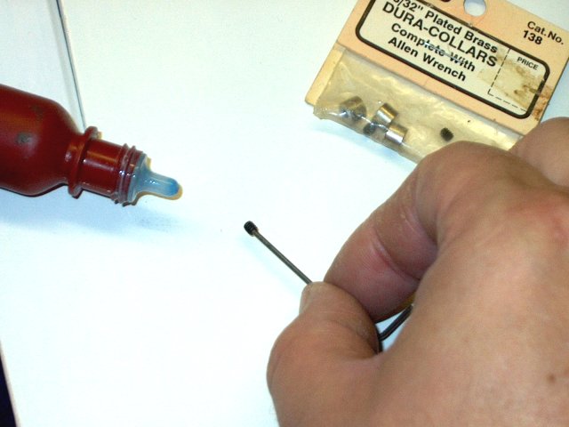
The connector comes with a retaining bolt,
but it is too long. You can instead use a 4-40 set screw from
a bag of small wheel collars to secure the pushrod. Apply
Loktite to the set screw | |
Apply Loktite to the connector retainer
threads and install the set screw | |
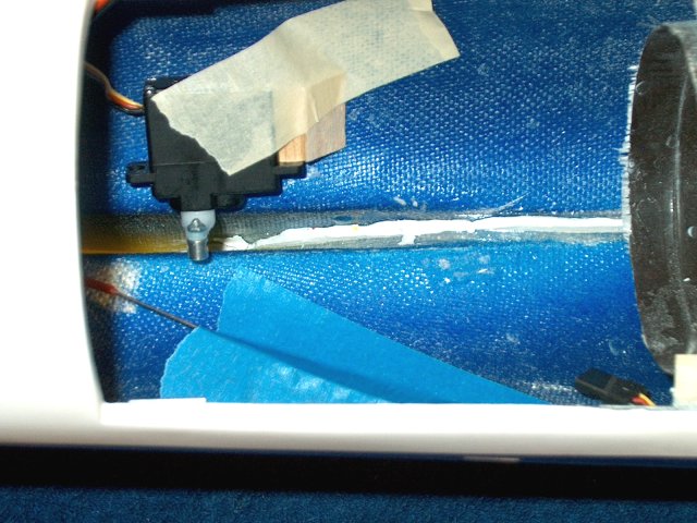
Slide the pushrod through the connector
and position the servo. Move the horn all the way toward the
red pushrod sleeve and position so there is still clearance as
shown | |
Make sure the pushrod is centered over the
vertical stab opening and mark the sides of the servo
| |
Rough up the servo area with 60 grit
sandpaper, sanding about 3/4" past each line
| |
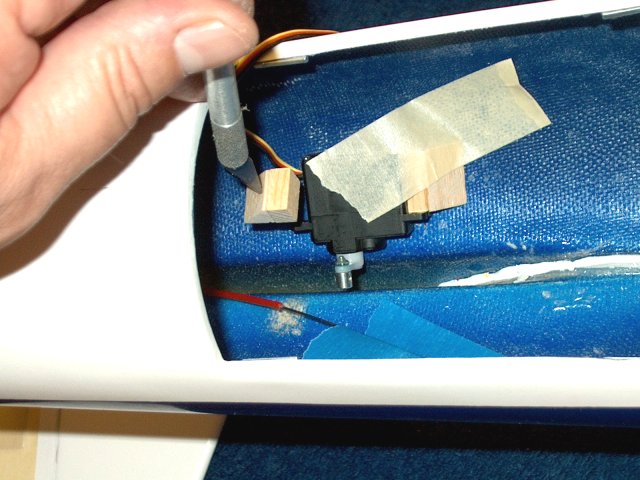
Apply fifve minute epoxy to the bottom of
the long hardwood block | |
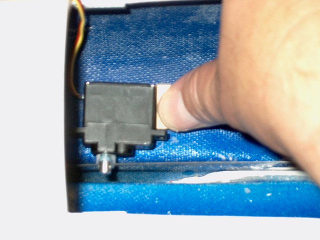
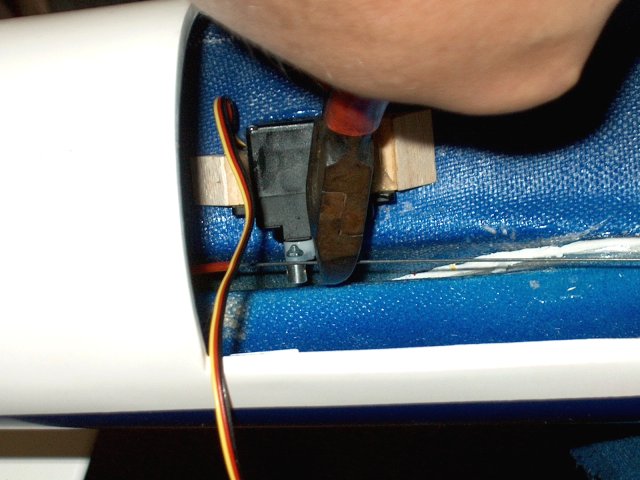
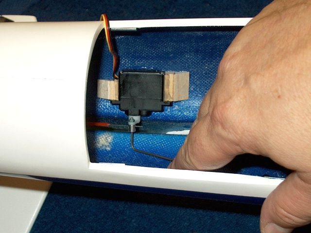
Hold the servo in place and install the
hardwood block. Make sure the servo is held square until the
epoxy sets | |
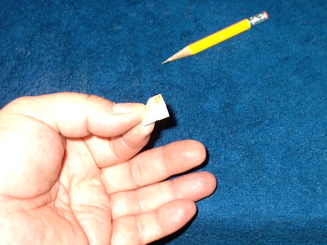
Apply epoxy to a piece of 1/2"
triangle | |
Install the triangle against the hardwood
block as shown | |
Install triangle stock to the short
hardwood block | |
Remove the pushrod from the servo and use
a piece of tape to hold the sevo in place
| |
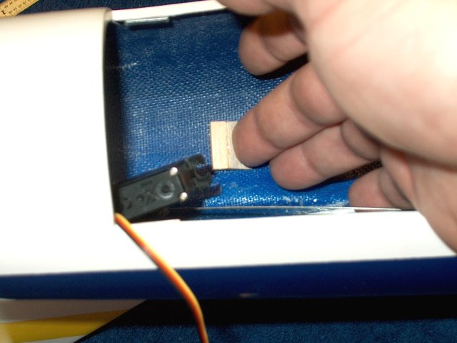
Apply epoxy to the the smaller hardwood
block and use a knife to install it against the side of the
servo | |
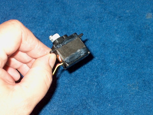
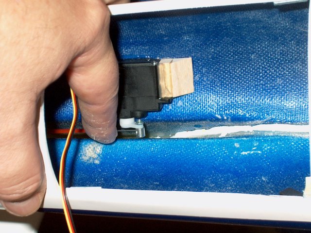
Remove the servo and install a couple
pieces of servo tape in the center to build up the area that
will be against the curved side of the fuselage. Apply an
ample ammount of clear silicon to the top and bottom of the
servo | |
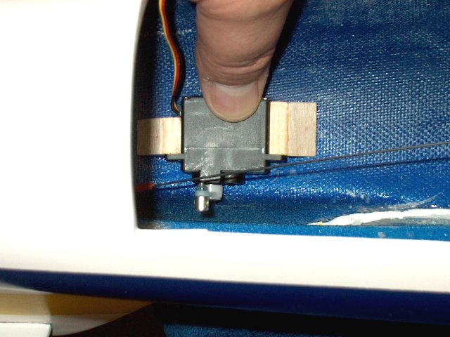
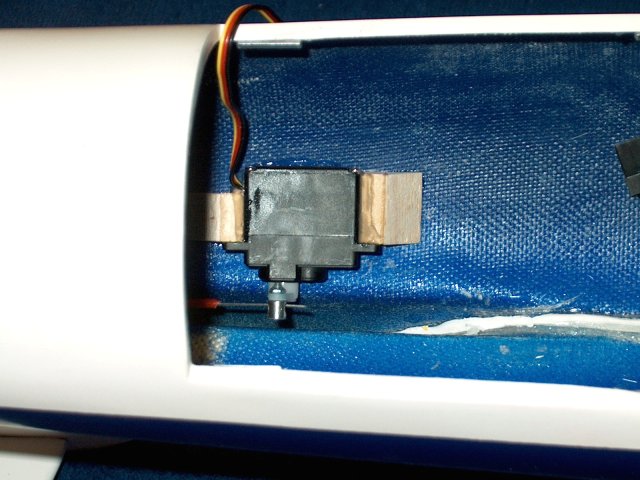
Install the servo between both blocks and
apply a bead of silicon across the top of each block where it
meets the servo | |
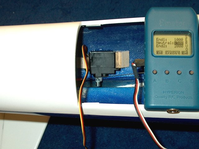
Hook up your receiver or servo tester once
again and center the servo | |
Clamp the Elevator so it is in a neutral
position | |
Cut the pushrod to length at least 1/4"
past the end of the horn connector | |
Unplug the servo from the tester, move the
arm to the right and install the pushrod. Center the servo
once more with your receiver or tester
| |
Use an allen wrench to tighten the
setscrew on the horn connector | |
Elevator Servo installation
completed | |
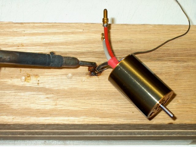
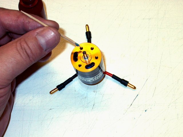
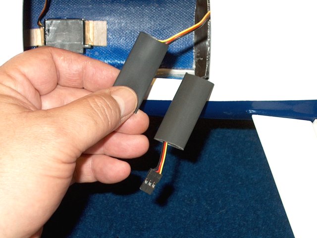
Install 3.5mm connectors on your motor
leads. Always use plugs on the non-power side
| |
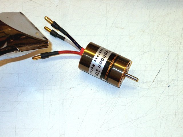
Install heatshrink over the plugs
| |
Apply Loktite ONLY to the motor threads as
shown and wipe up all excess. DO NOT get Loktite on the
plastic parts or it will disintegrate them. You can also use
Green Loktite, which is plastic safe
| |
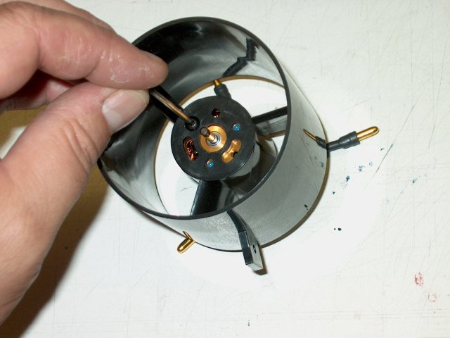
Install the motor into the fan shroud
(HET-RC 6904 Ducted Fan shown). If you are using a HET-RC
motor, you can use three bolts for the installation. Do not
tighten the bolts | |
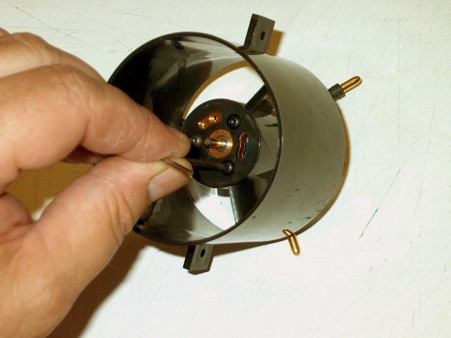
Slide the heatsink (supplied with HET-RC
Fan) lip end first, over the rear of the motor, then apply a
few drops of CA to the inner lip and install it flush inside
the shroud. The heatsink will help center the motor
| |
Tighten the motor mount bolts
| |
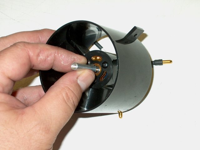
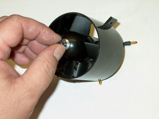
Install the fan adapter over the motor
shaft | |
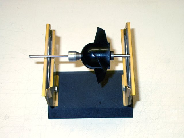
Make sure the fan is balanced. HET-RC 6904
Fans come pre-balanced, but check them anyway and balance if
necessary. See installation instructions for your fan or find
them at www.warbirds-rc.com | |
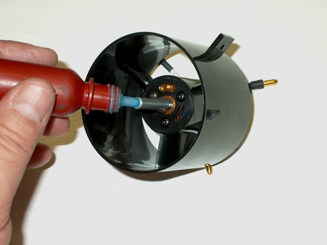
Apply some Loktite to the center adapter
shaft | |
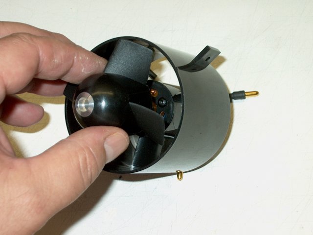
Install the Fan over the adapter
shaft | |
Install the fan retaining bolt
| |
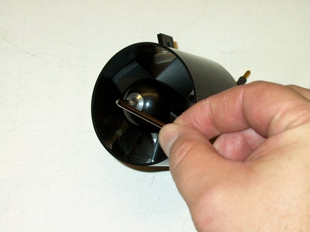
Tighten the retaining bolt, making sure
there is at least 1/16" clearance between the rear of the fan
and the front of the shroud motor mount area. Check for free
movement once tightened | |
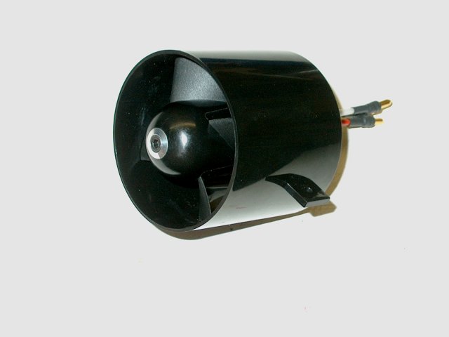
Fan assembly completed
| |
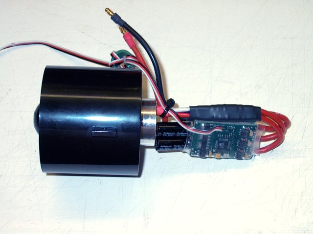
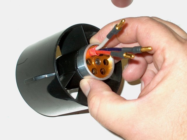
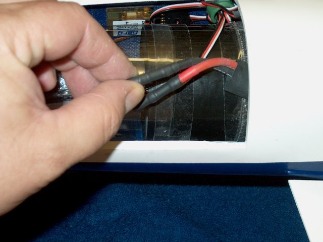
Plug the three ESC wires into the motor
and use a piece of large heatshrik to keep them from pulling
apart. Dress up the assembly with tie wraps
| |
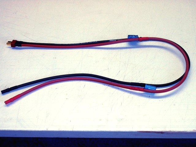
Two feet of 12ga Deans wire was used and
sockets for the ESC power wires were installed at one
end | |
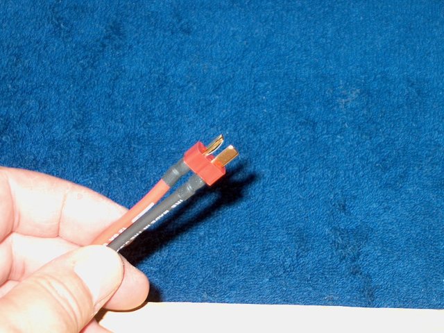
Install a Deans Ultra Plug at the other
end of the wires. Note the orientation of the black and red
wires | |
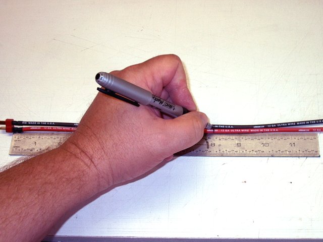
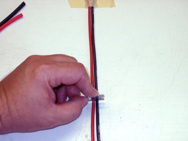
Make marks on the wire harness at 8" and
16" away from the power plug end | |
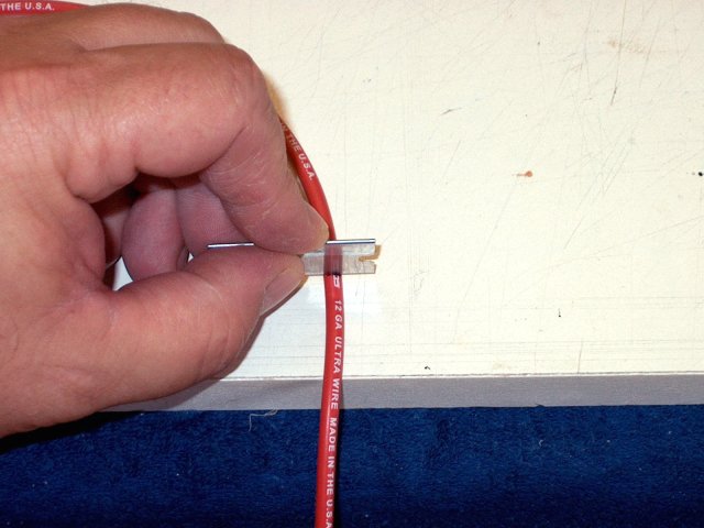
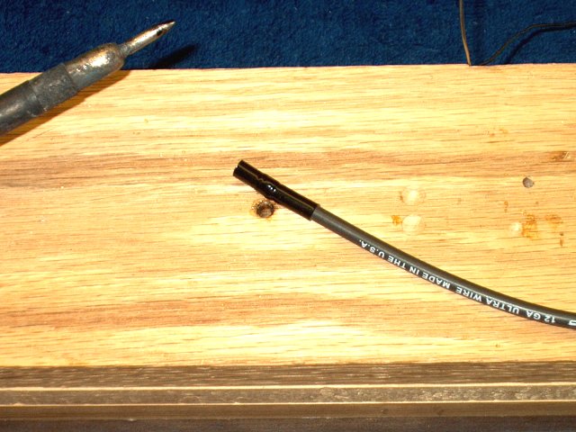
Make a cut at each mark with a razor,
cutting only through the rubber insulation
| |
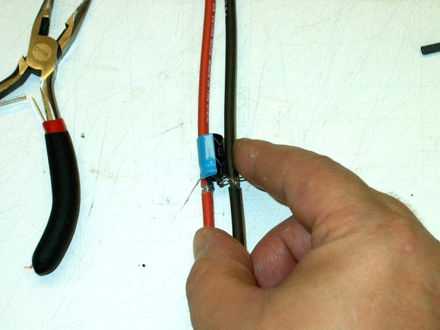
Make a second cut about 1/8" past the
first | |
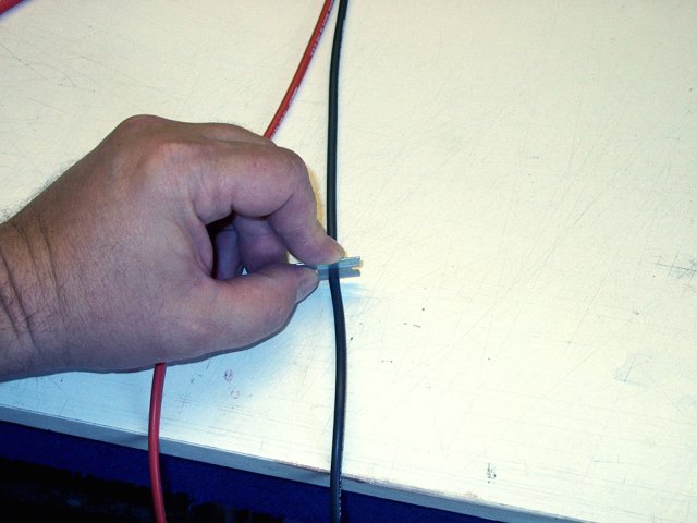
Using the first wire for reference, make
two similar cuts to the other wire | |
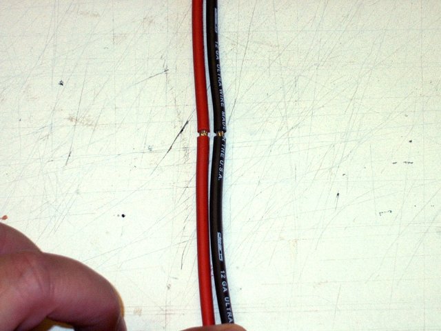
Cuts shown completed, showing bare wire.
Make similar cuts at the 16" marks | |

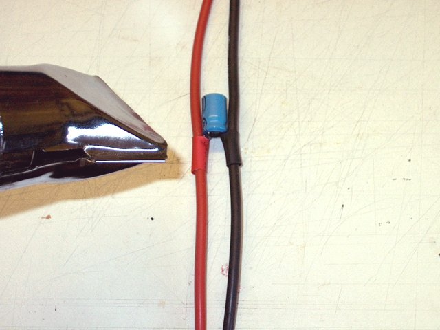
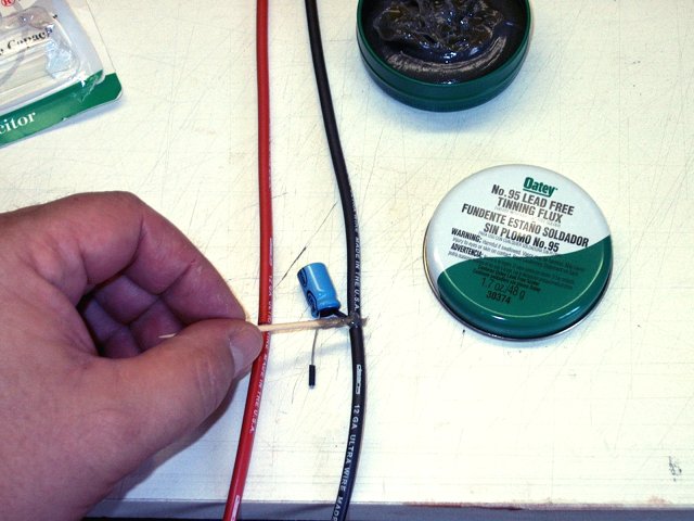
Use Rosin and solder to tin each
wire | |
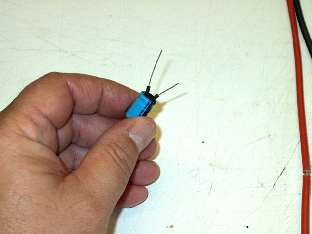
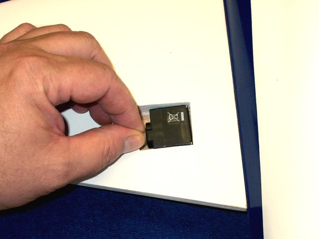
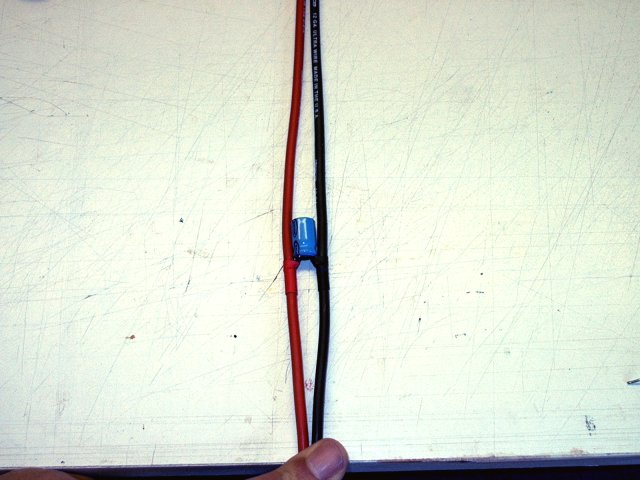
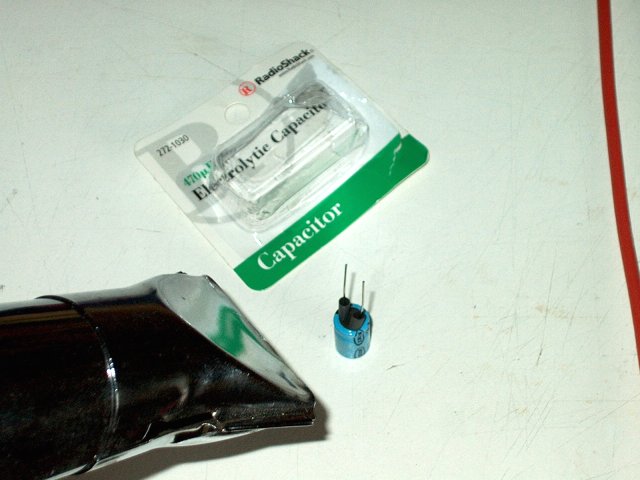
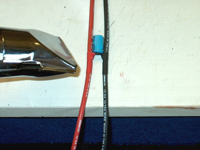
Install some small heatshring on two leads
of a 470uf Electrolytic capacitors, available at Radio Shack,
part # 272-1030 | |
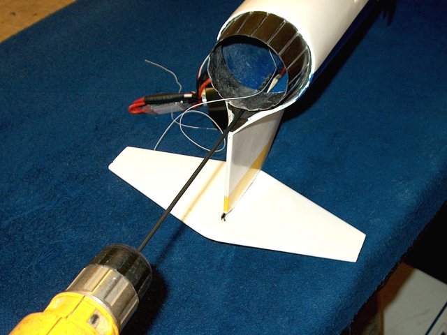
Pull the rod through the motor area,
working the harness to the back | |
Tape the harness ESC wires to the side of
the fuselage for now so they don't get pushed forward
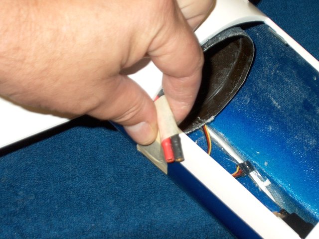
| |
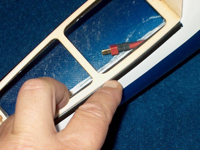
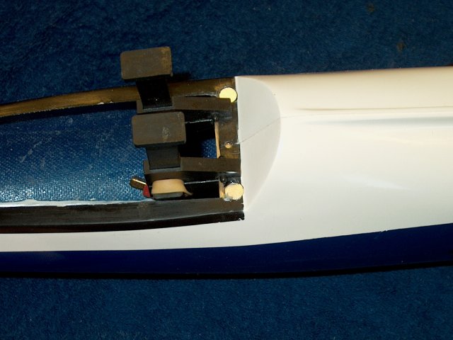
The Battery leads are shown in the correct
position under the cockpit area | |
Slide some heat shrink over the Aileron
servo leads | |
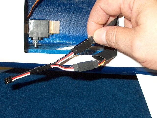
Connect the Aileron leads to a "Y"
harness | |
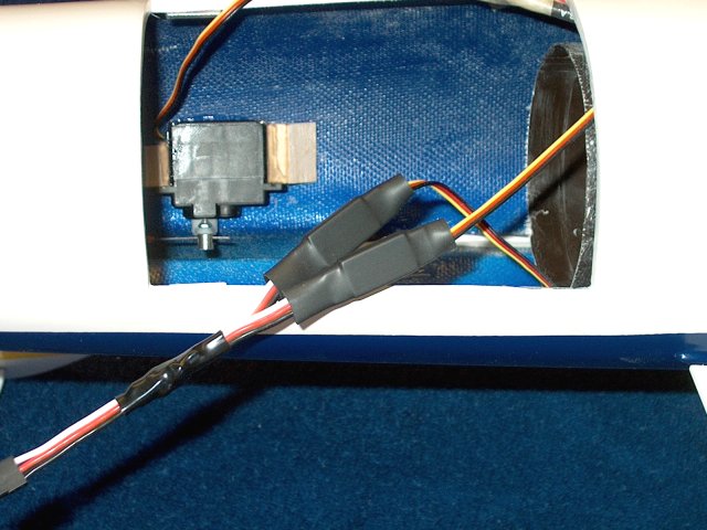
Seal the heatshrink around the servo plugs
so they cannot be pulled out by accident
| |
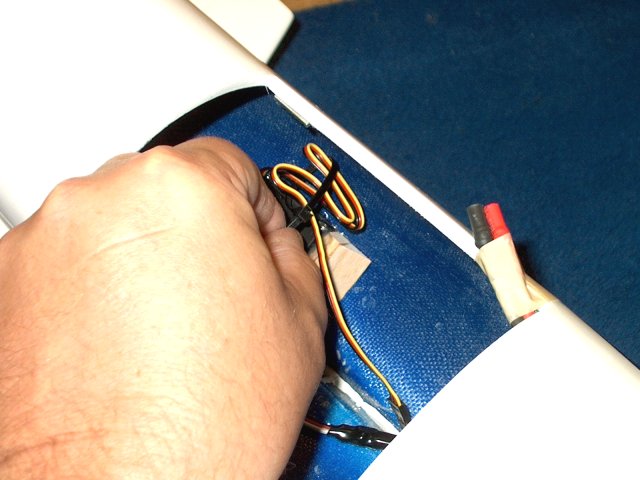
Use a tie wrap to gather up the excess
Elevator servo leads if necessary | |
Apply a couple layers of servo tape to the
bottom of your receiver. Be sure to use a full range, high
quality receiver for this model | |
Remove the backing from the tape and
install the receiver on the side of the fuselage
| |
If you are using a power configuration and
require the use of an external BEC, apply servo tape to the
bottom of your BEC unit or receiver battery pack. A 400mah
NiMH receiver pack is shown | |
Remove the backing fom the servo
tape | |
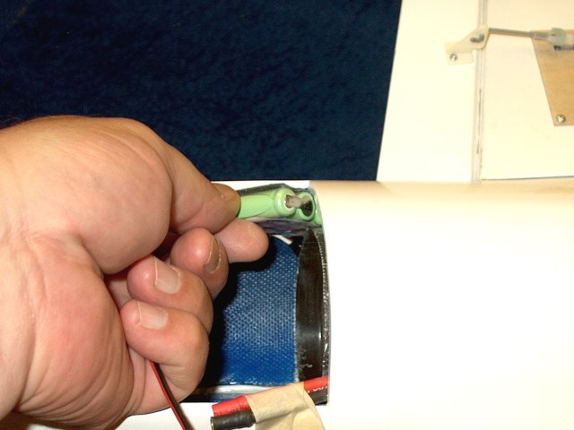
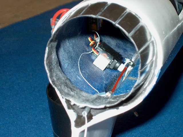
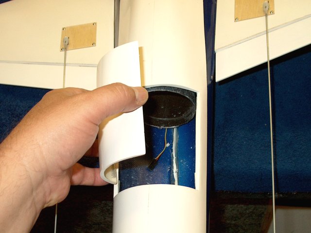
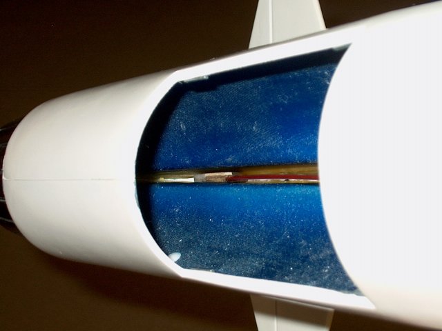
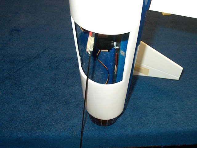
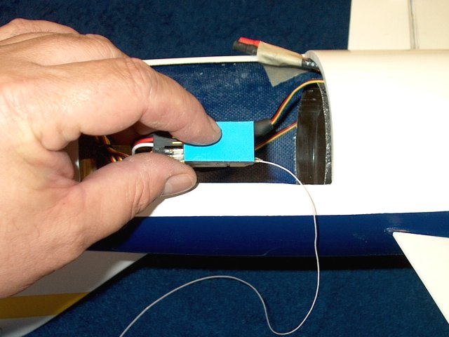
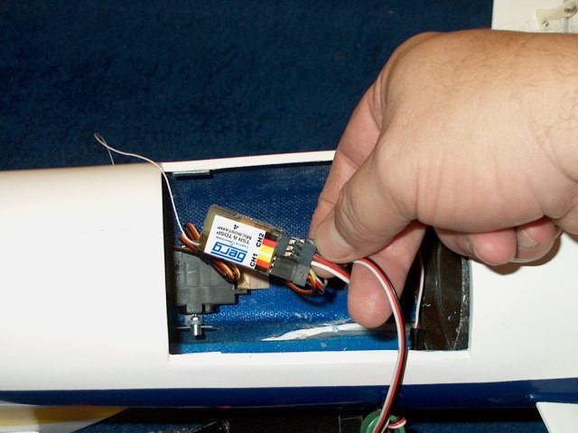
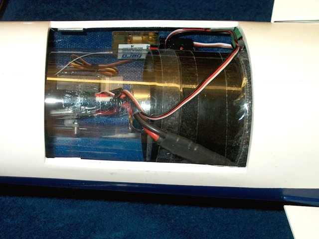
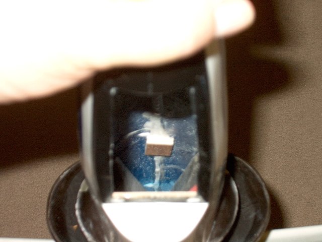
The Battery or BEC is positioned in the
bottom center of the fuselage, just behind the intake's fan
lip | |
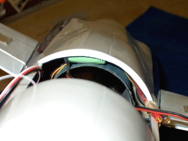
Closeup of BEC location
| |
NOTE: Antenna placement may differ on your
model depending on the type of receiver you use. ALWAYS range
check before flying. Drill a 1/8" hole between the vertical
stab and exhaust, centered on the bottom of the stab
tail | |
Install a piece of antenna tube in the
hole that was drilled | |
Extend the tube into the fuselage about
1/4" past the inside wall and make a mark on the outside about
1/8" past the exhaust as shown | |
Cut the antenna tube to length
| |
Rough up the bottom side of the tube that
will be glued with 60 grit sandpaper
| |
Apply a bead of epoxy along the sanded
bottom of the antenna tube | |
Install the tube in the fuselage. A
toothpick makes a good tool to ease installation
| |
Center the tube over the vertical stab
tail, then tape the toothpick down to hold the antenna tube in
place until the epoxy sets | |
Remove the masking from the outside of the
tubing | |
Clean any marks you made with
alcohol | |
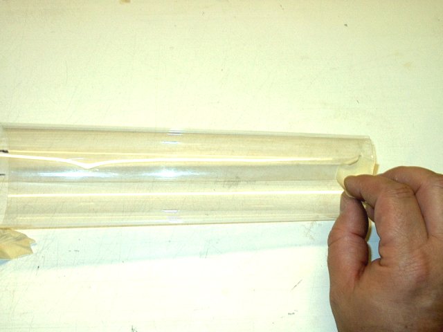
Tape the tube , seam side up, to a hard
surface as shown | |
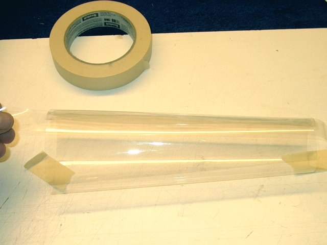
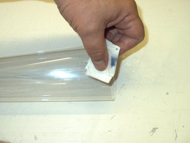
Apply a 1" wide strip down the center of
the outer seam of the tube | |
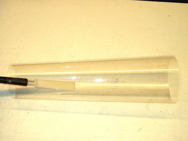
Use a burnishing tool to press the tape
down the entire length of the seam | |
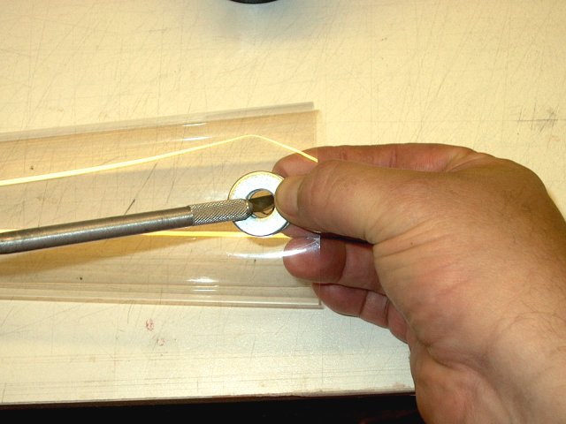
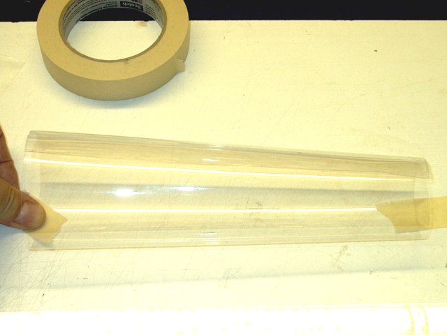
Use two large 3/8" washers sandwiched
between the plastic as a cutting jig to cut a circle near the
fan end of the tubing for the ESC wires. Make the hole about
3/4" from the end of the tube | |
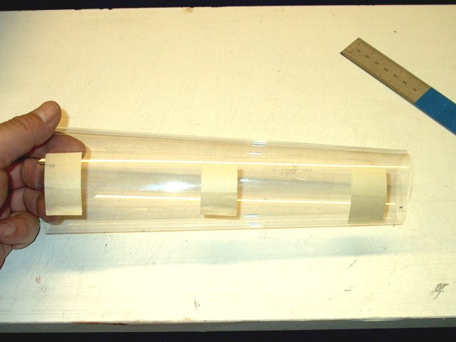
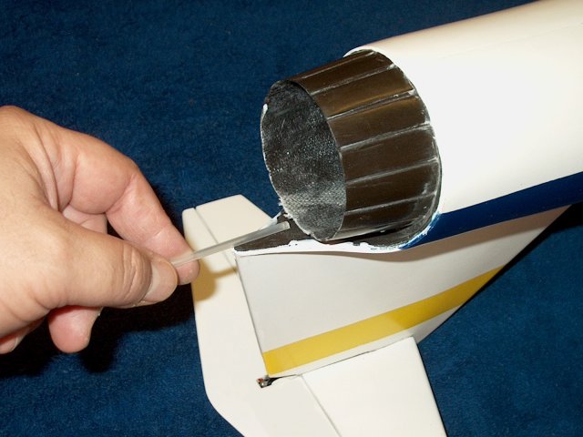
Temporarily install the tube over the fan
and mark the outside where it exits the fuselage
| |
Cut the excess tail material from the
tube | |
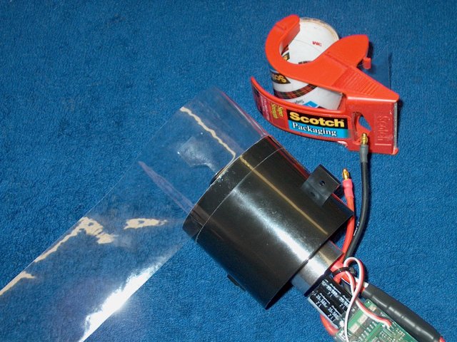
Install the tubing in the fuselage. Fold
it first as shown for easier installaion
| |
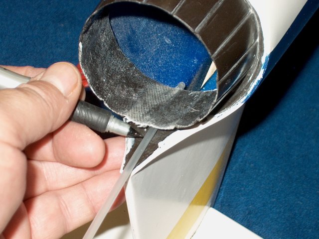
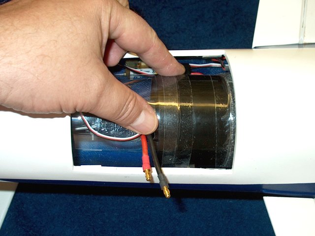
Run the wires of your ESC through the hole
cut in the thrust tube | |
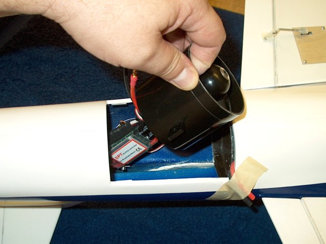
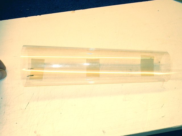
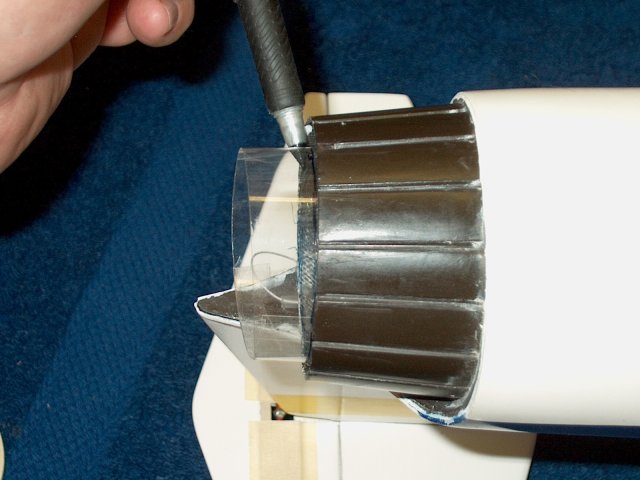
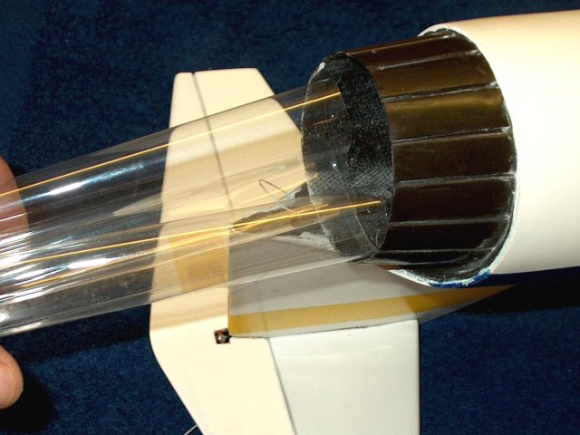
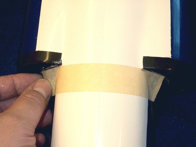
Install the tube over the fan unit, then
use a 3/4" wide strip of packing tape to secure it
| |
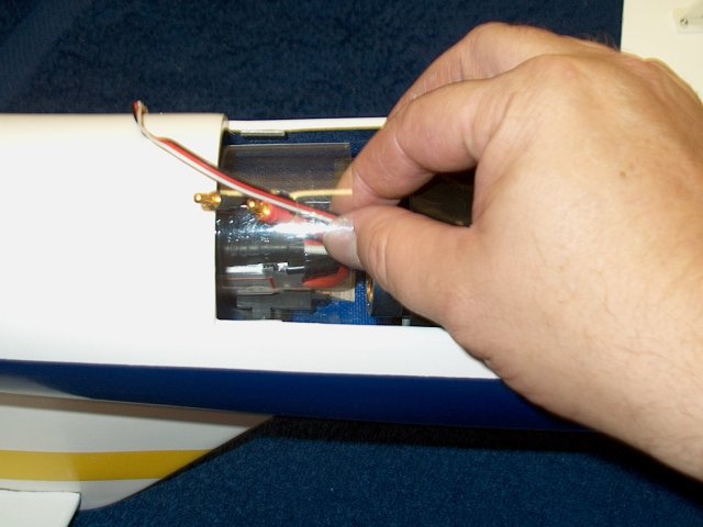
Connect the two ESC power wires to the
harness, then use heat shrink to hold them in place. Plug the
ESC control wire into the receiver | |
Power assembly installation
completed | |
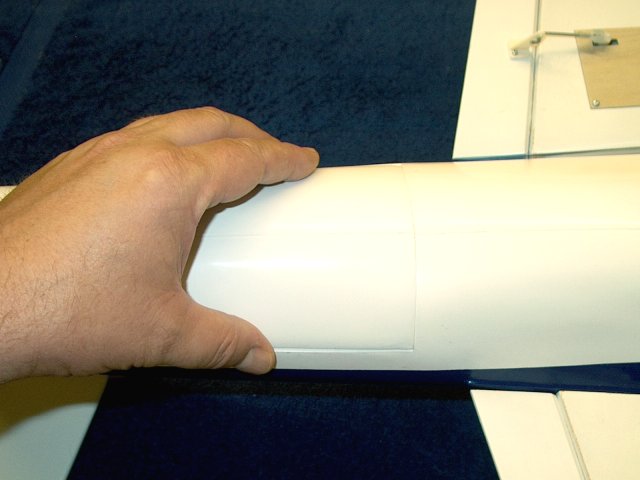
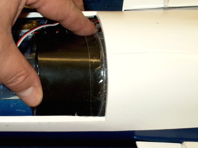
Install the cover over the fan
compartment. A couple strips of clear tape can be used to
insure it holds in place | |
Basic fuselage assembly is
completed | |
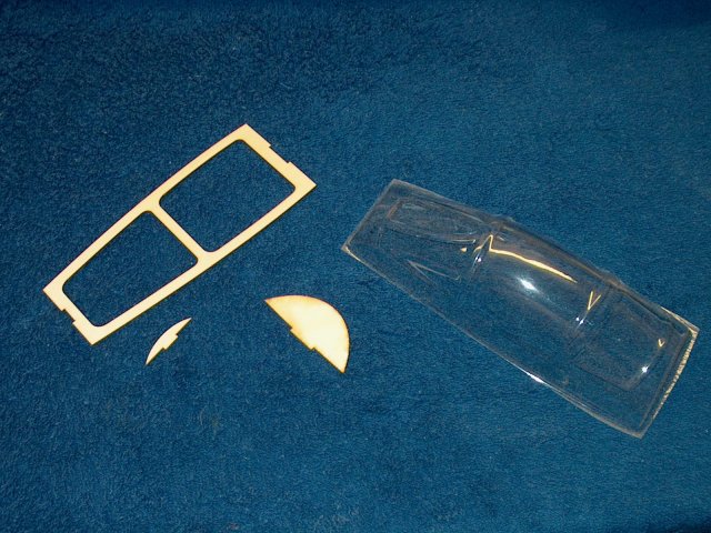
Gather the parts from the kit that you
will need to assemble the cockpit | |
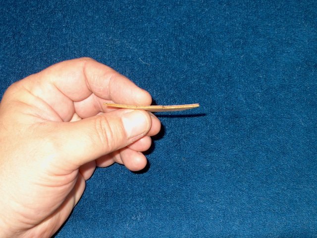
The larger piece was badly warped
| |
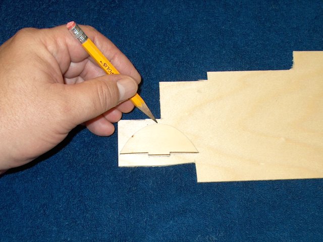
A new piece was drawn and cut from a scrap
sheet of ply | |
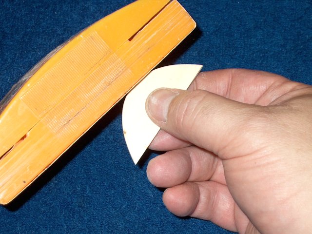
Stack the two pieces and sand the new
piece until it is even with the original
| |
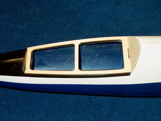
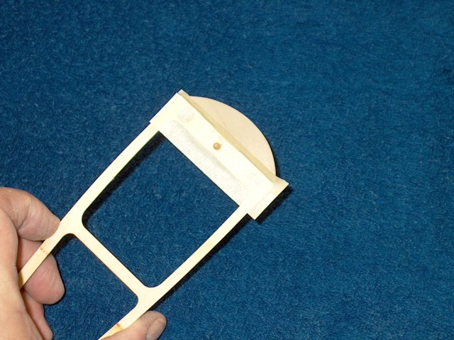
Install the two end pieces into the
cockpit frame and check for fit | |
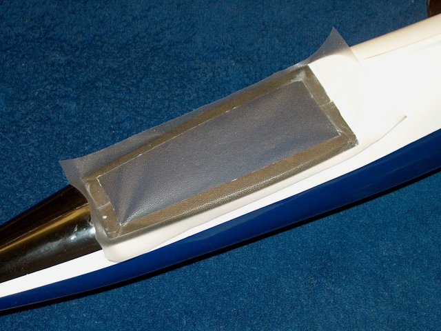
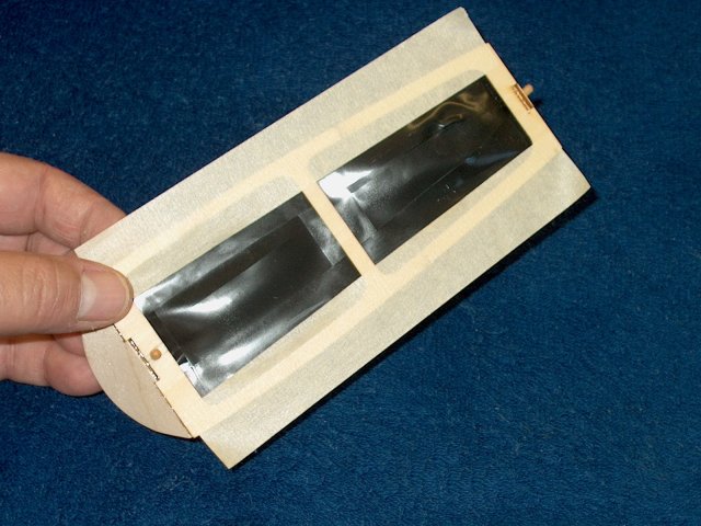
Cover the cockpit area with thin plastic
wrap | |
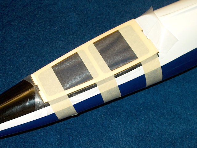
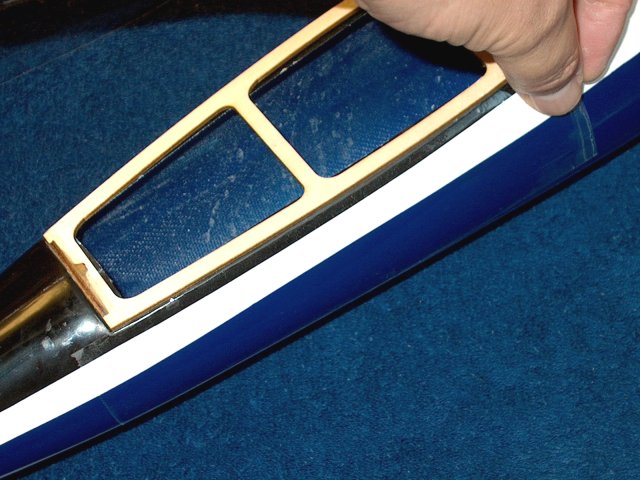
Install the cockpit frame, making sure it
is centered at the front and back. Tape the frame in
place | |
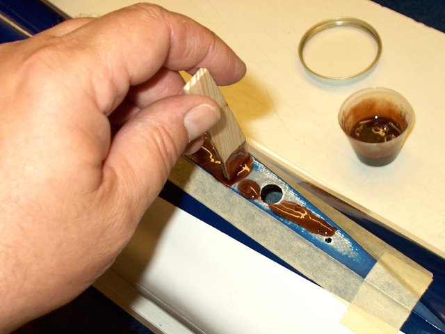
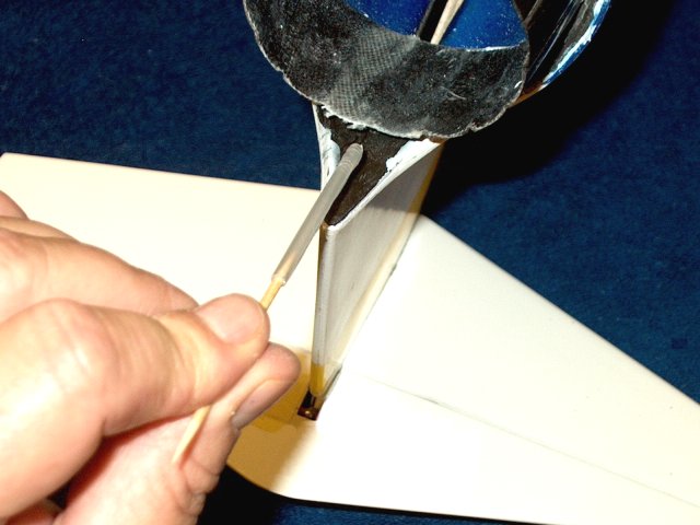
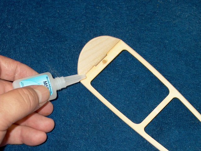
Apply epoxy to the small forward ply
piece | |
Install the piece in place as shown. Use a
toothpick to apply a small fillet of epoxy at the joint for
strength | |
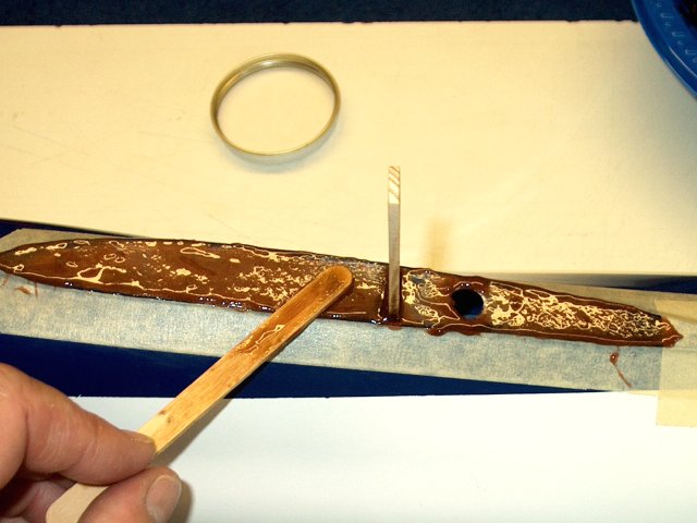
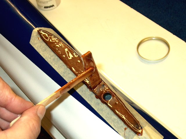
Apply epoxy to the rear ply piece
| |
Install the piece in place and tape it
flush to the rear of the cockpit area. Allow the epoxy to
set | |
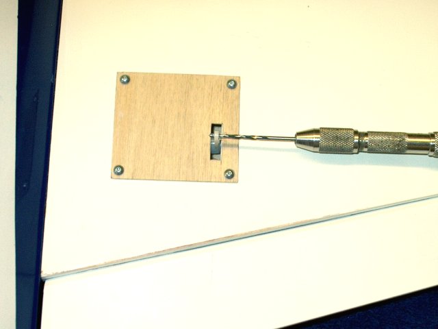
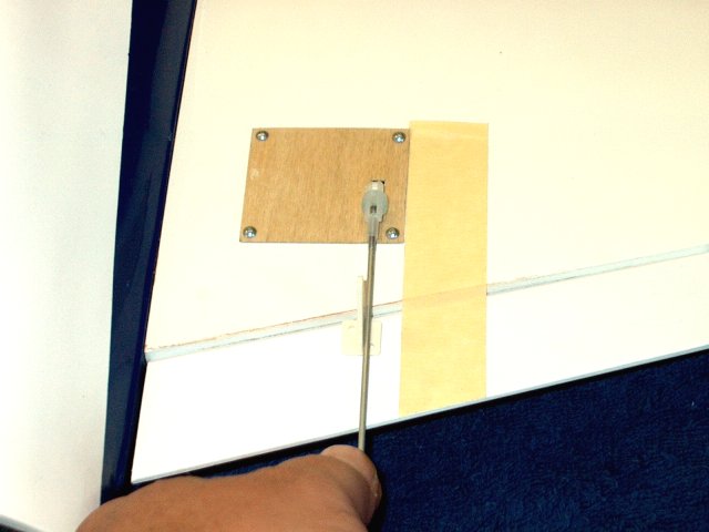
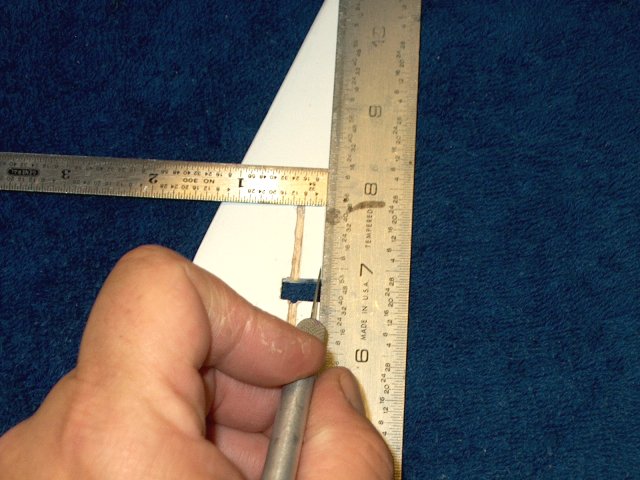
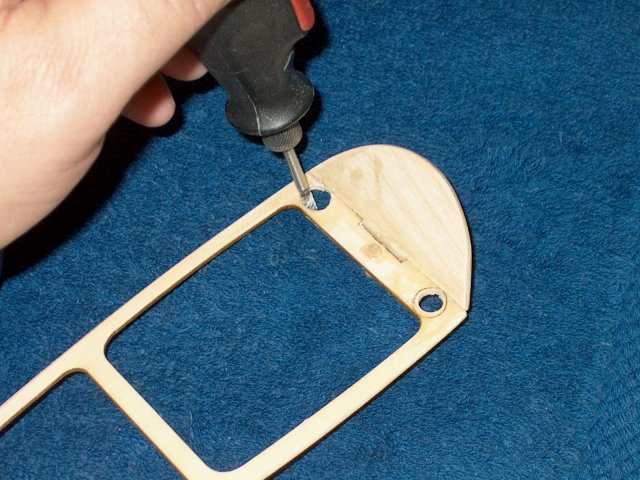
Drill the center of the front cockpit wall
with a 1/8" bit | |
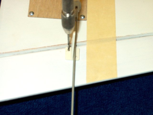
Install and center the cockpit frame, then
use tape to hold it in place and use a hand drill to continue
the hole through the front plate to the fuselage
| |
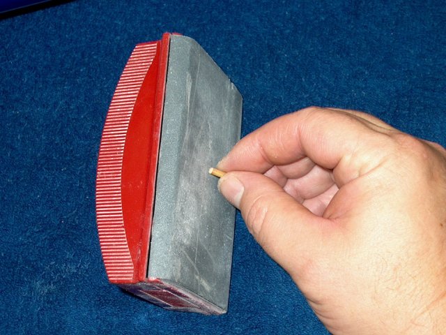
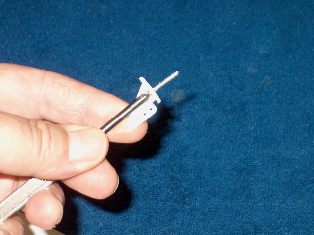
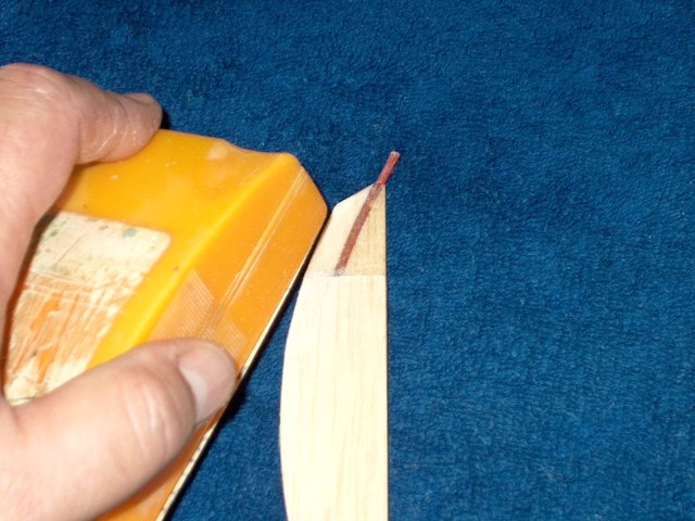
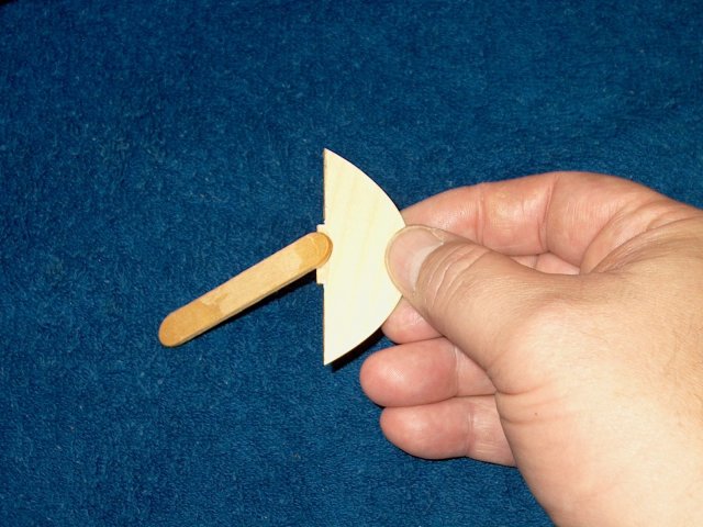
Round one end of the supplied wood dowel
so it will more readily install in the fuselage
| |
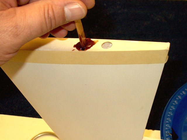
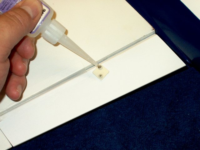
Epoxy the dowel in the hole, applying
epoxy only to the wood frame and dowel and not the fiberglass
fuselage | |
Add a small fillet of epoxy around the
dowel pin | |
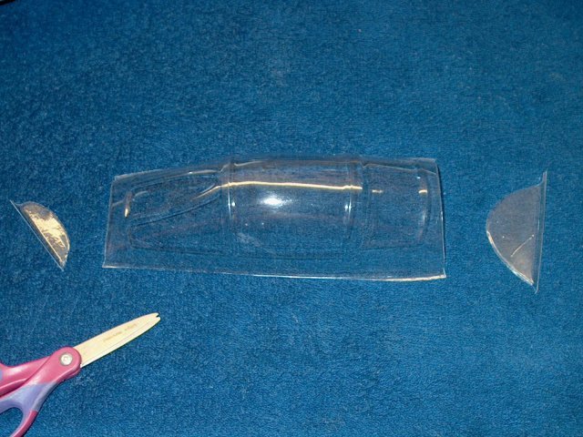
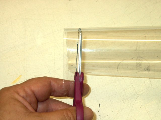
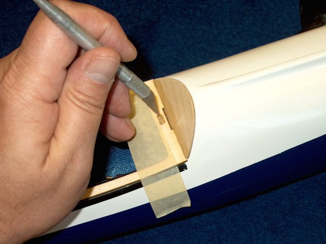
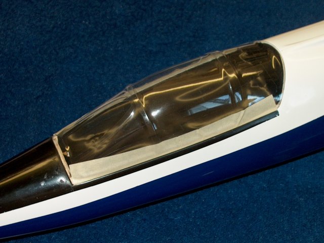
Cut the ends off the canopy. Trim as
little as possible to remove the end caps
| |
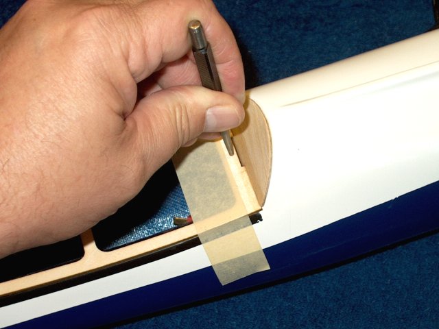
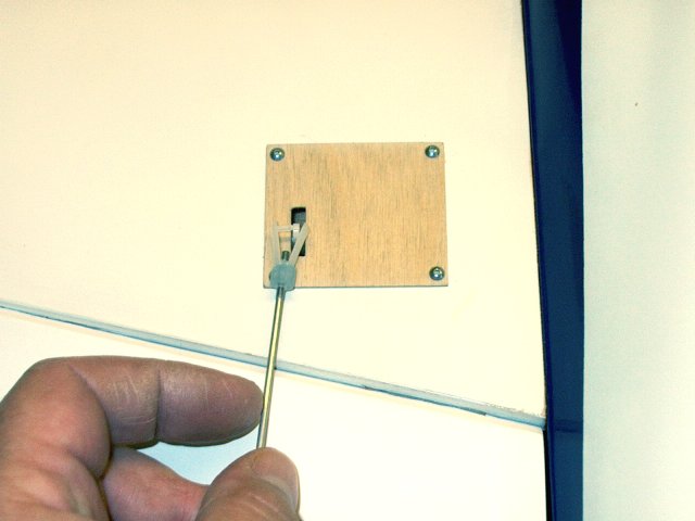
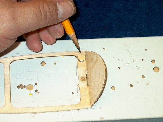
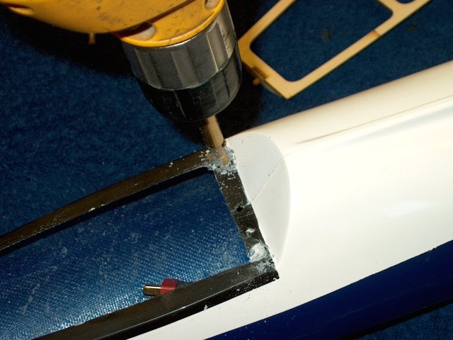
Use a punch to make a center mark in the
rear of the cockpit frame as shown | |
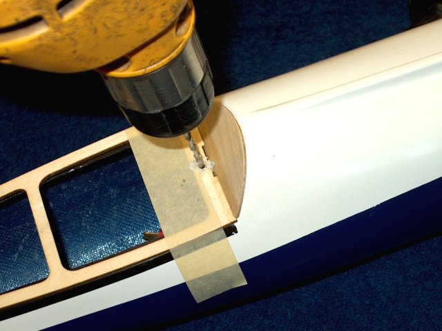
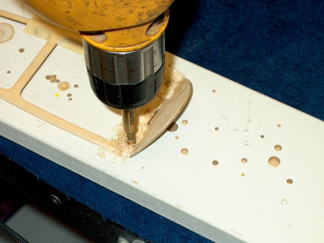
Drill through the frame and fuselage with
a 1/8" bit | |
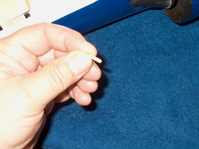
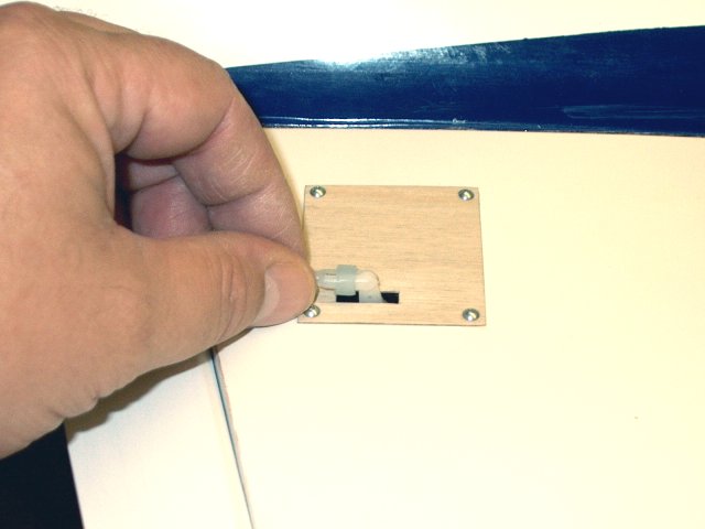
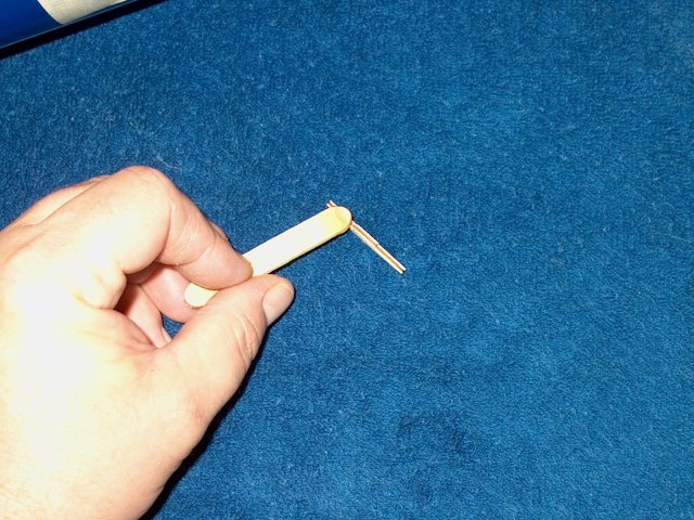
Make a pin 1/2" long from a piece of scrap
1/8" diameter wood dowel and round one end
| |
Install the pin as shown, leaving a little
bit of the pin exposed at the top. | |
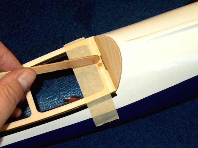
Add a fillet of epoxy around the dowel
pin. This pin will be used to insure the rear of the cockpit
is centered when installed | |
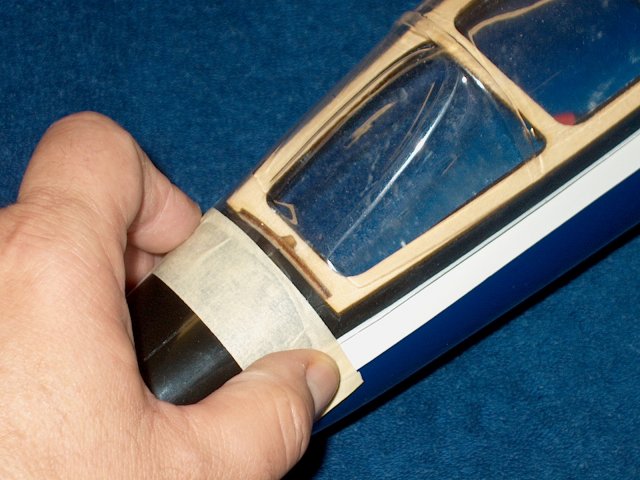
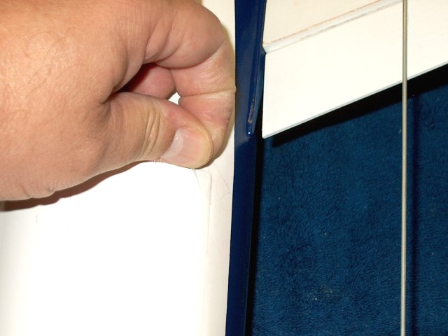
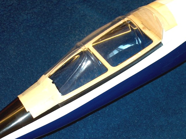
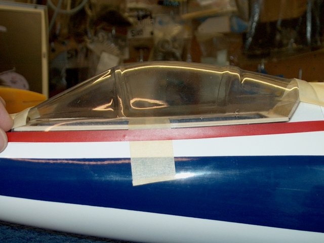
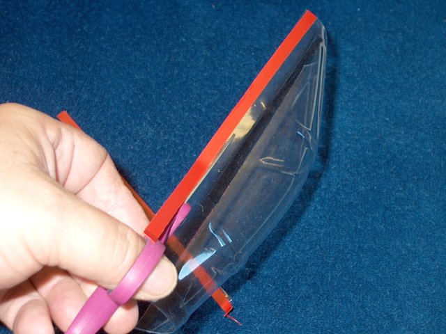
Center the canopy on the front of the
fuselage, making sure the window frame is centered and the
side windows are the same distance from the cockpit frame.
Tape the canopy in place as shown | |
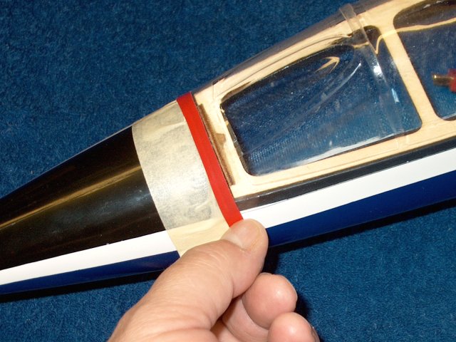
Use some vinyl trim tape on the canopy to
mark a cutting point that is flush with the firewall
|
|
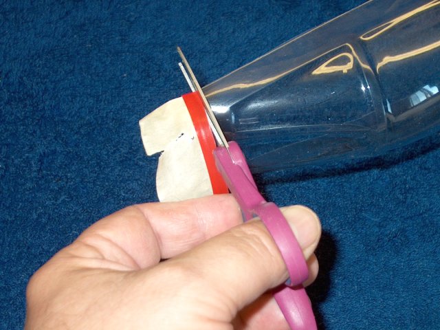
Cut along the tape and remove the excess
material | |
Lightly sand the canopy front so it is a
perfect fit, then tape it's edge flush to the fuselage
firewall. Center and secure the rear of the canopy with
masking tape | |
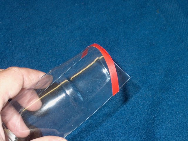
Using the same method, mark the rear of
the canopy with vinyl tape, then remove and trim it. Check the
fit on the fuselage | |
Apply some clear packing tape, then
masking tape to the sides, front and back of the
fuselage | |
Sand the sides so they match the inward
taper of the fuselage | |
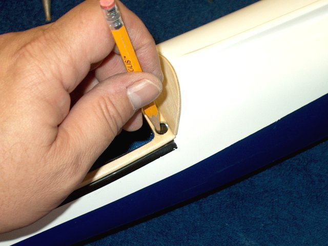
Draw a edge mark with the back of a pencil
along both sides of the cockpit frame. Lightly sand to the
line so the edges of the frame will be slightly
recessed | |
Sanding the sides will leave a small lip
at the fuselage joint as shown. This recess allows the canopy
to sit flush with the sides of the fuselage
| |
Center the canopy an tape it down at the
front and back. Use vinyl tape along the edges to mark a cut
at the fuselage shelf | |
Remove the canopy and cut the canopy at
the mark. You may have to repeat until you have a good
fit | |
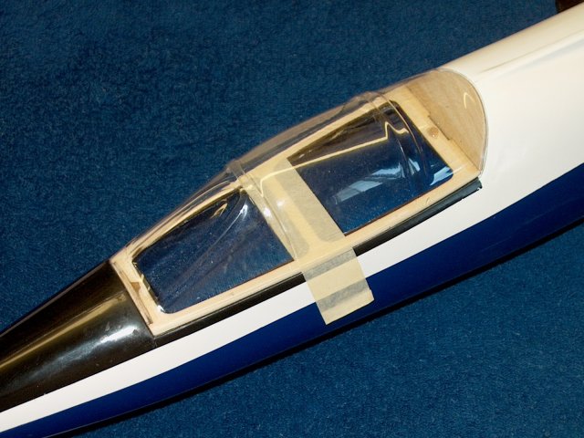
Canopy fitting completed. Detail the
cockpit as desired | |
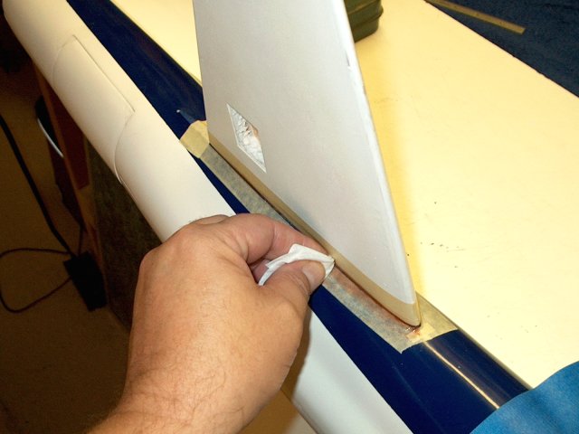
Appl masking tape along the bottom of the
cockpit frame as shown | |
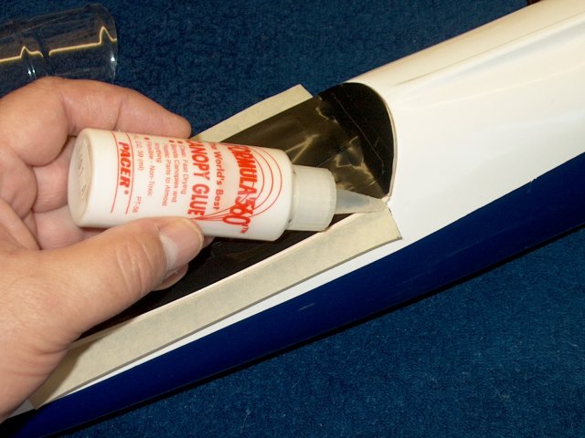
Apply canopy glue to both sides of the
cockpit frame | |
Position the canopy, holding it tight to
the frame, then fold the masking tape up to hold the canopy in
place while the glue dries | |
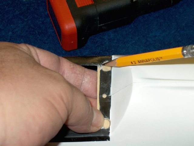
Apply CA to the rear corners of the
cockpit frame on both the top and bottom sides
| |
Position a magnet as shown and mark its
location with a pencil. Repeat for the other corner
| |
Drill the holes with a 1/4" drill or
forstner bit | |
Carefully enlarge the holes with a dremel
and router bit. Do not over-enlarge
| |
Place the frame on the fuselage and
transfer the hole locations to the fuselage with a
pencil | |
Drill the hole with a 1/4" bit or
forstner. Open the holes so the magnets fit tightly.
| |
cut a piece of 1/32" ply 1/2" wide and to
a length equal to the width of the fuselage rear. This will be
used to support the magnets | |
Apply Epoxy to the ply and install it in
place | |
Clamp the plate and before the epoxy sets,
install two magnets in the holes so they are flush with the
top of the fuselage | |
Apply masking tape to the bottom of the
cockpit frame | |
IMPORTANT: Check the position of the two
top magnets so they attract rather than repel from the magnets
in the fuselage. They must be mounted on the correct side.
Rough up the opposite side of each magnet
| |
Press the magnets into the frame holes IN
THE CORRECT DIRECTION so they are flush with the tape on the
bottom of the frame | |
Apply Epoxy to the hole filling the well
and allow the glue to set | |
Apply a piece of masking tape to the
bottom of the fuselage even with the front lip of both
intakes | |
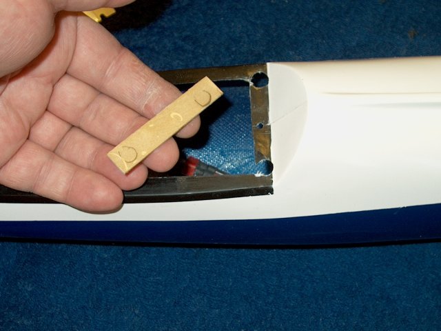
The block inside the fuselage for the tow
hook is shown | |
Measure and make a mark 1/4" behind the
tape at the center seam of the fuselage
| |
Drill the hole with a small drill for the
towhook |
|
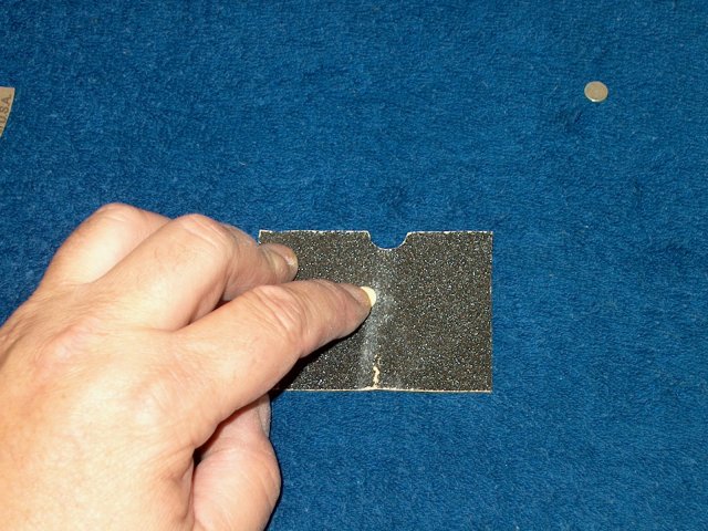
Rough up with 60 grit sandpaper the
towhook on the side that inserts into the fuselage
| |
Apply epoxy to the towhook and hole in the
fuselage | |
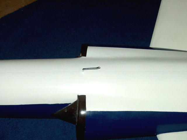
Install the towhook and clean up any
excess epoxy with alcohol. Make sure the hook is pointing
straight back | |
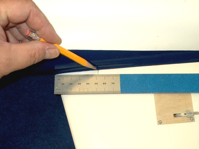
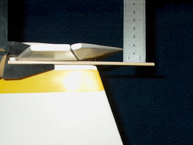
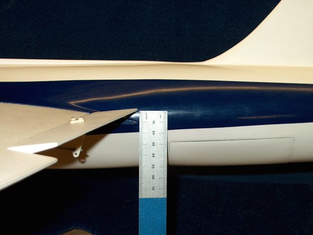
Mark the CG location at 52mm back from the
leading edge of each wing as shown | |
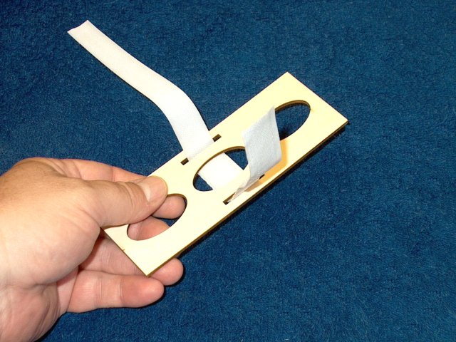
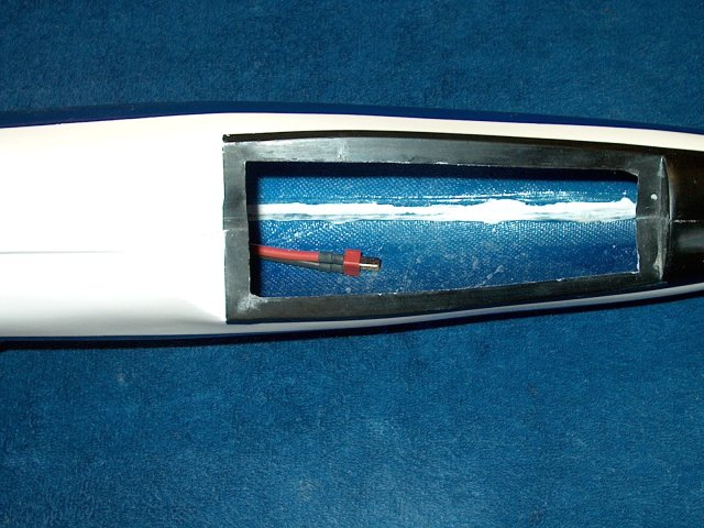
Install the retainer strap in the supplied
battery tray as shown. Some Epoxy can be applied along the the
bottom side edges of the straps to make sure it does not pull
apart | |
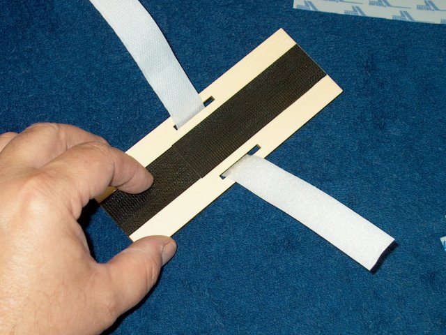
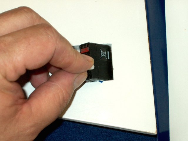
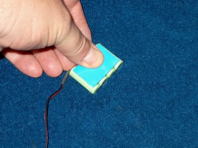
Add a long strip of Velcro to the entire
length of the battery tray. Also apply a couple squares of
Velcro cloth to the battery itself. This method allows
re-positioning of the battery for CG and prevents the battery
from slipping backward, which is what happens if the straps
are used without Velcro added to the tray
| |
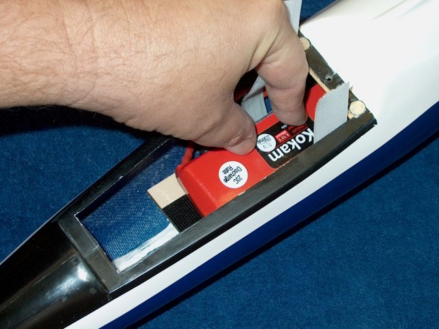
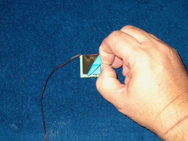
Install the battery and tray in the
fuselage | |
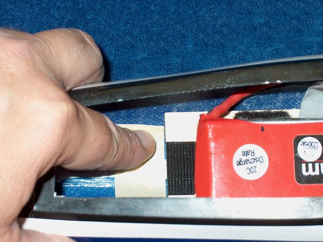
Move the assembly forward or backward
until CG is achieved, then mark the front location of the tray
with masking tape | |
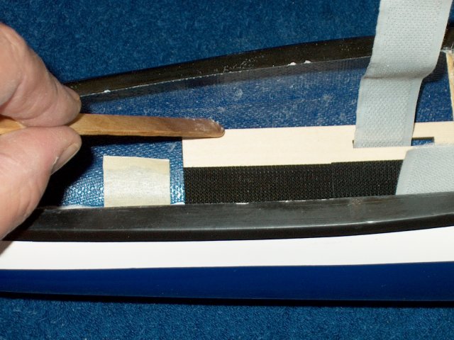
Remove the battery and position the tray
to the tape's edge, then apply epoxy along the edges of the
battery tray, gluing it permanently in position
| |
Adjust Elevator throws to 15mm UP
| |
Adjust Elevator throws to 10mm DOWN and
set Expo at 60% for a starting point if desired
| |
Adjust Aileron throws to 12mm up and 6mm
down | |
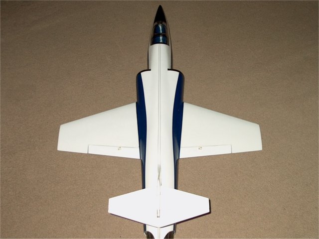
F-104 Top View | |
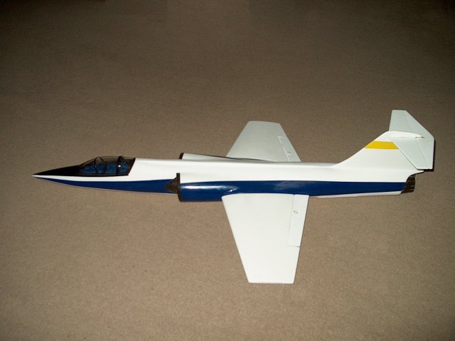
F-104 Side View
| |
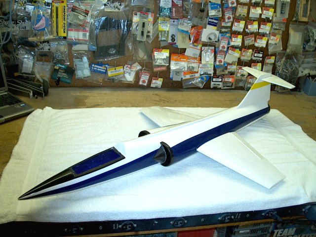
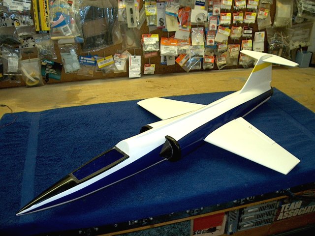
The HET-RC F-104 Starfighter EDF Jet
| |

This Website and all documents herin are Copyright © 2012 www.scalerocketry.com -
All rights reserved.
| |