Dolly Bungee Launcher Build Instructions


1.jpg
2.jpg
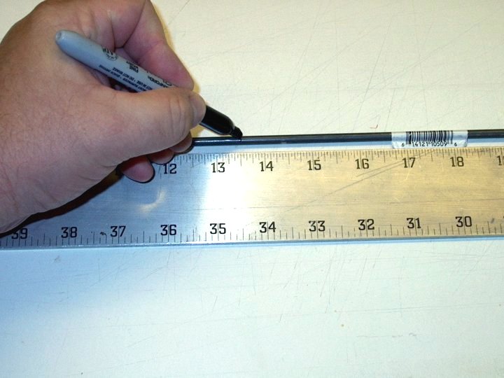
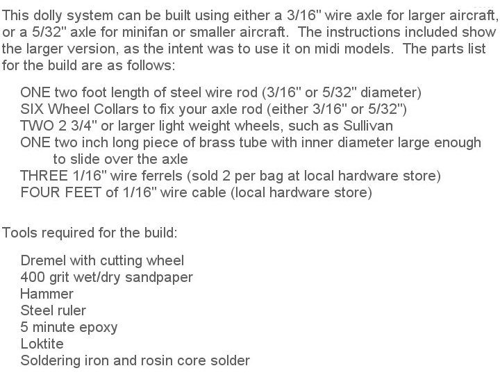
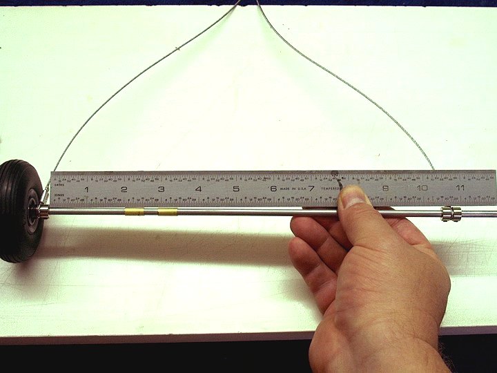
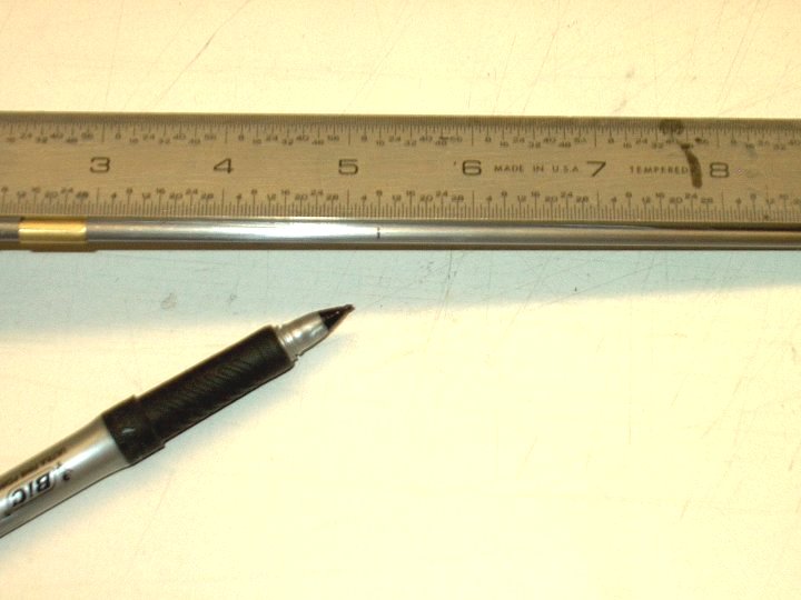
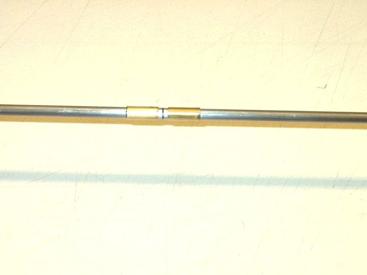
2 - A 3/16" piece of steel rod from the hobby shop is used for an axle. It is marked for cutting at 13 1/2" in length
3.jpg
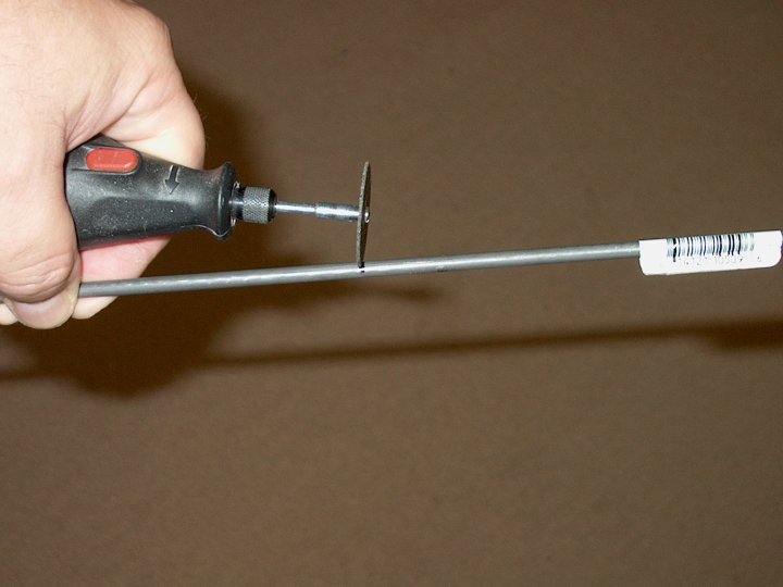
3 - The rod is shown being cut and the ends are then flattened
4.jpg
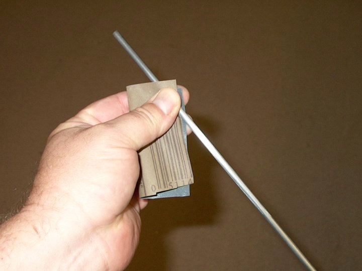
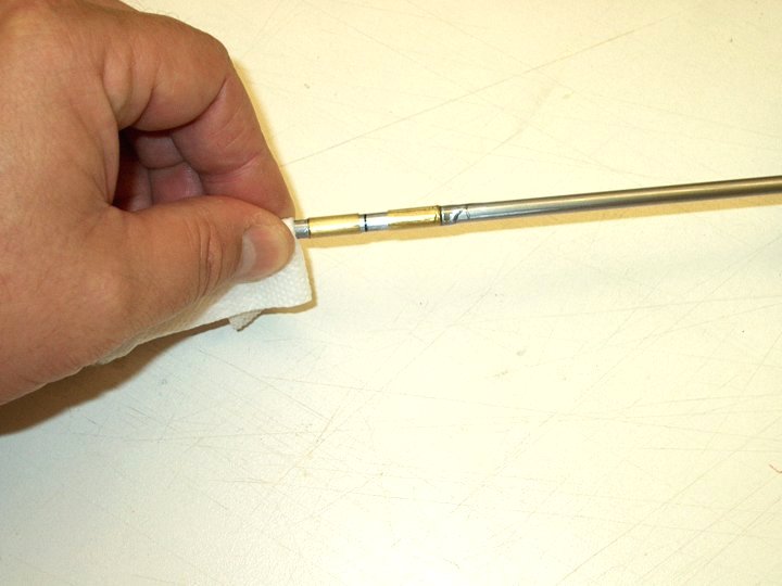
4 - The rod is cleaned with very fine sandpaper, followed by alcohol CG.
5.jpg
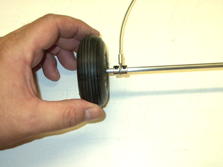
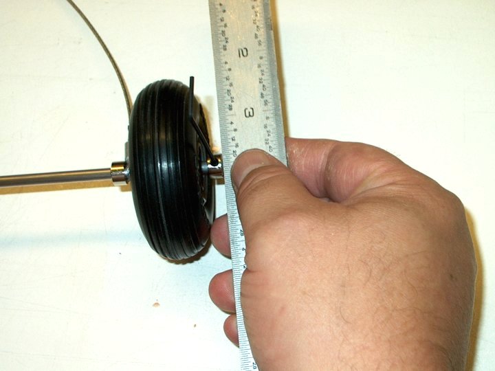
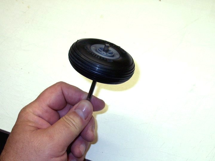
5 - Most wheels have 5/32" axle holes, so I used a spare pair of 2 3/4" lightweight wheels and drilled them to 3/16" diameter to fit the axle
6.jpg
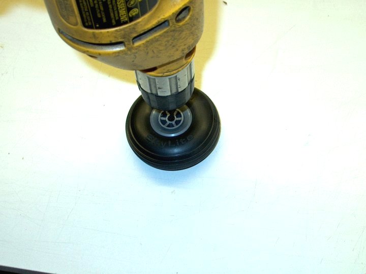
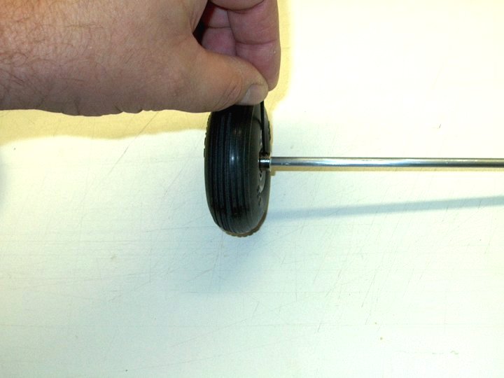
6 - You may have to sand/file the hole so it spins smoothly and without play on the shaft rod you made
7.jpg
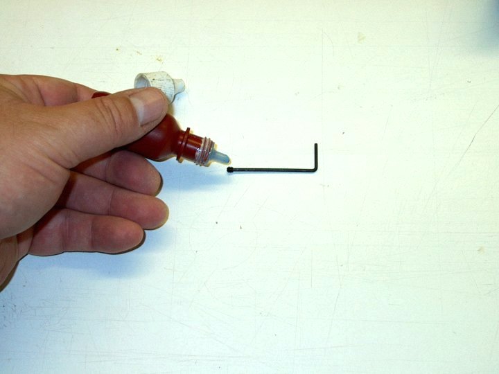
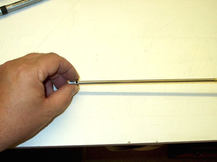
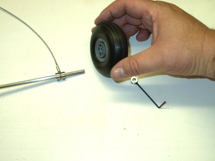
7 - Loktite is used to install the set screws in six 3/16" wheel collars that are used
8.jpg
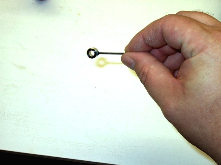
8 - Set screw shown installed in wheel collar
9.jpg
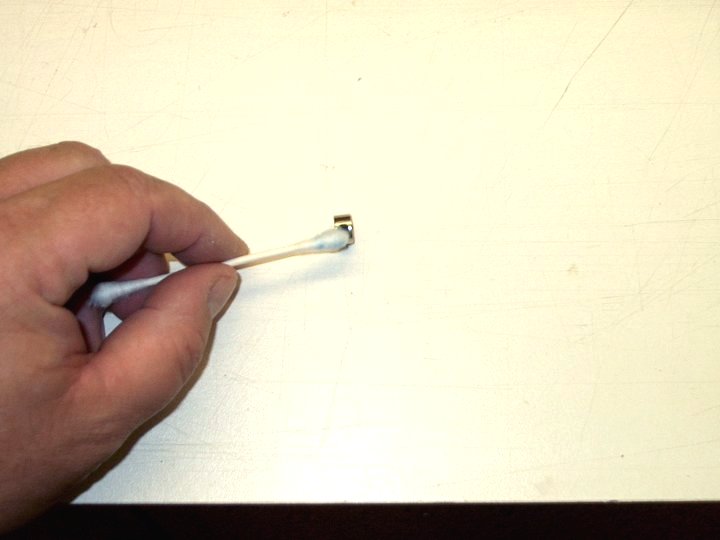
9 - Clean up the excess Loktite with a Q-Tip
10.jpg
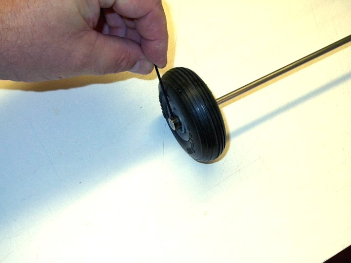
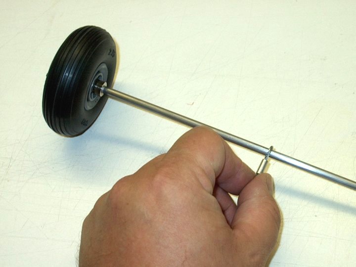
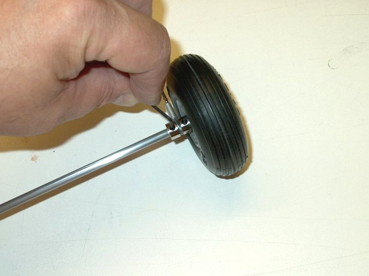
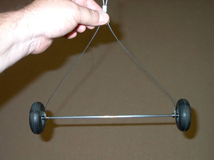
10 - The first Wheel is installed and the Wheel Collar is tightened flush to the shaft
11.jpg
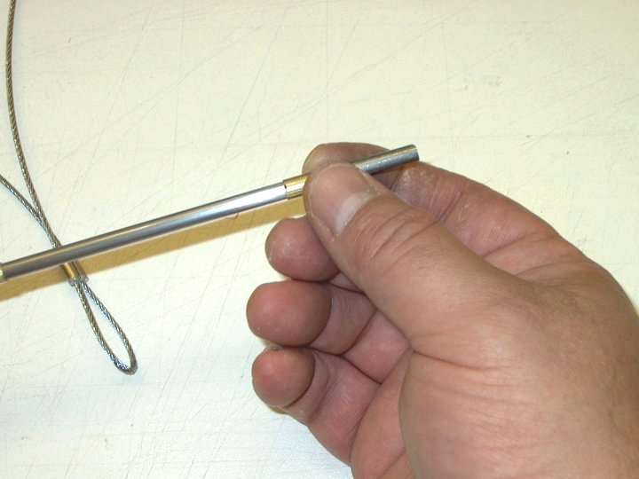
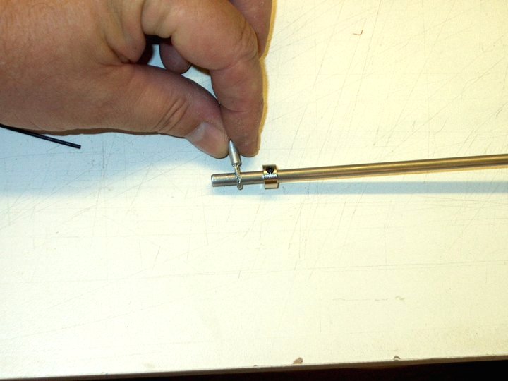
11 - A second wheel collar is installed to hold the wheel in position. Make sure the inside wheel collar is not binding so the wheel can spin freely
12.jpg
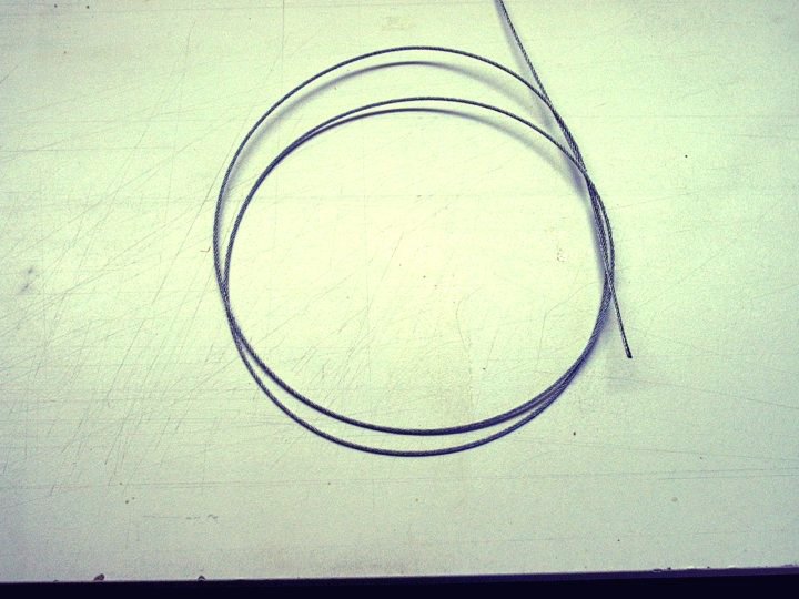
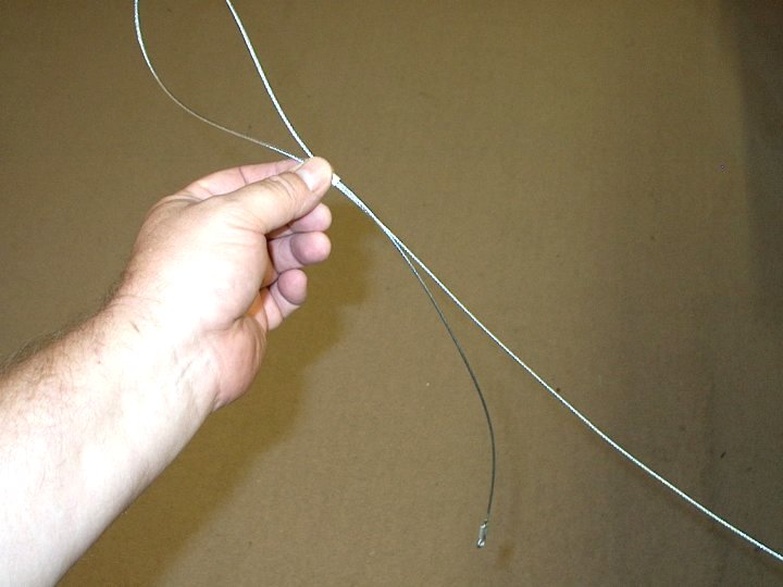
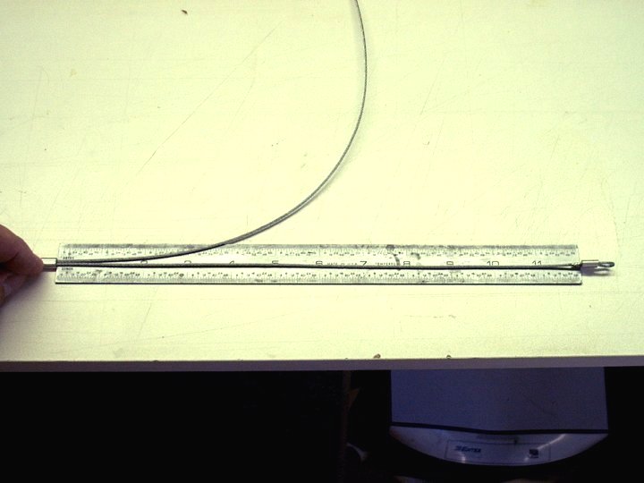
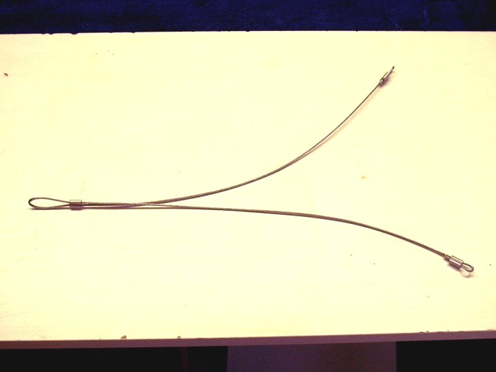
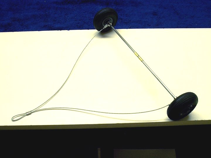
12 - 1/16" braided steel cable is purchased from Home Depot, Lowes or any other similar store. You will need about three feet of cable

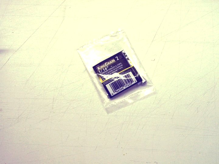
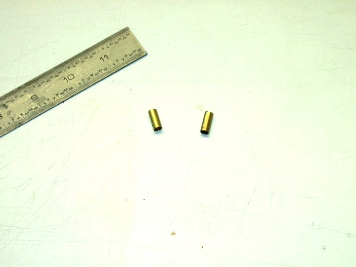
13 - Aluminum Ferrels are also purchased for the wire. You will need three of them and they come two to a pack
14.jpg
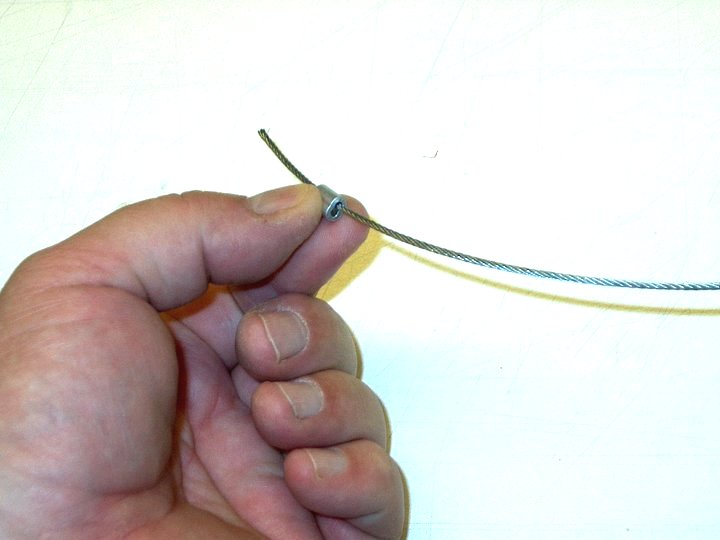
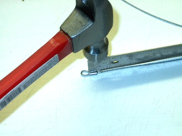
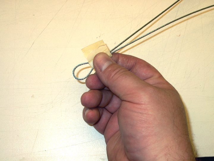
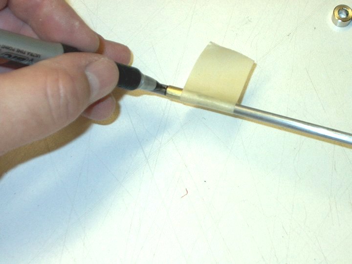
14 - The first ferrel is placed over the wire end
15.jpg
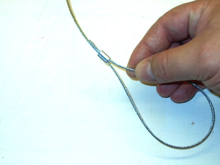
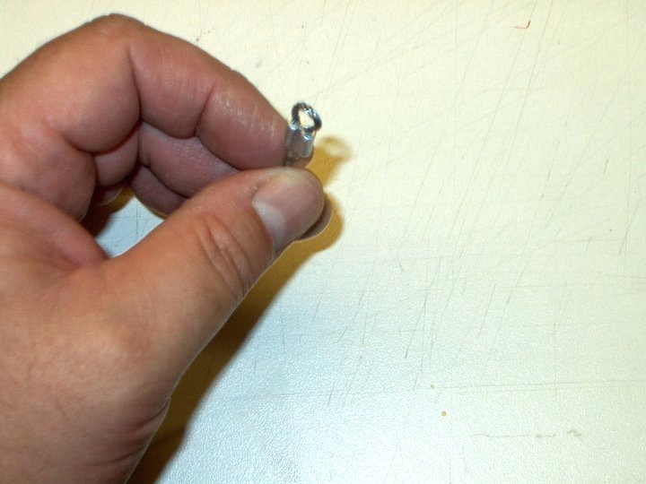
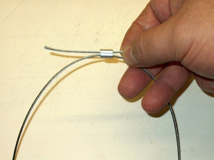
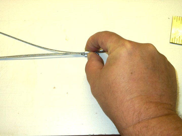
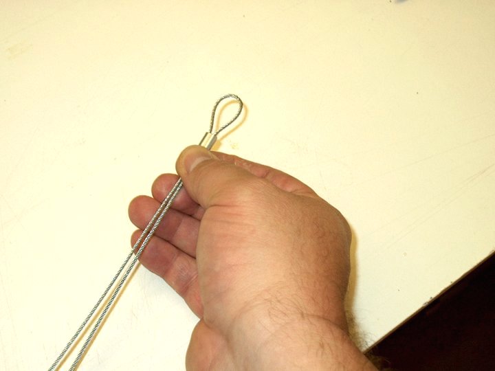
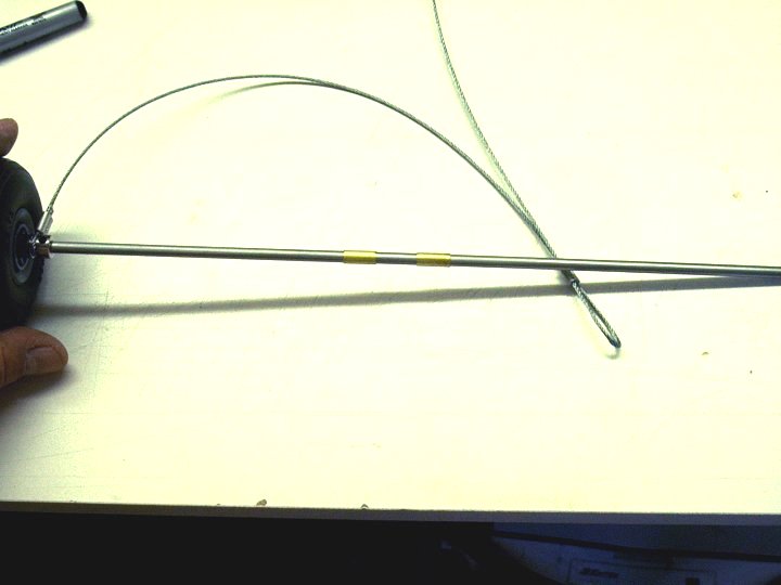
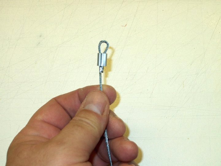
15 - The wire is looped around and inserted into the other side of the ferrel
16.jpg
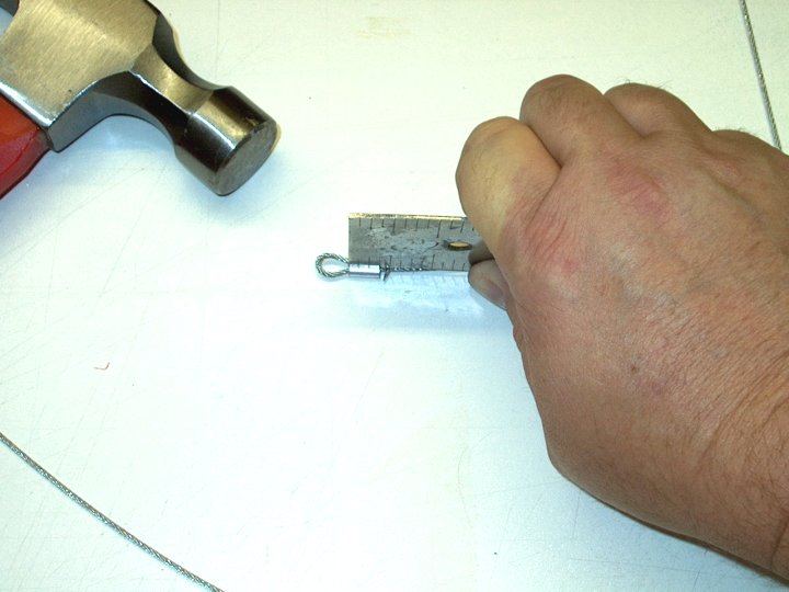
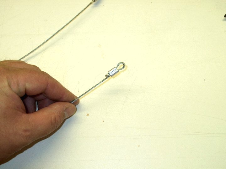
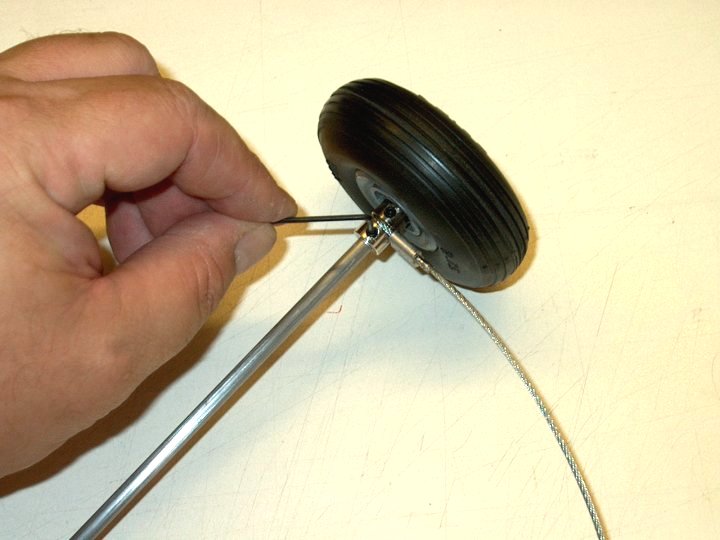
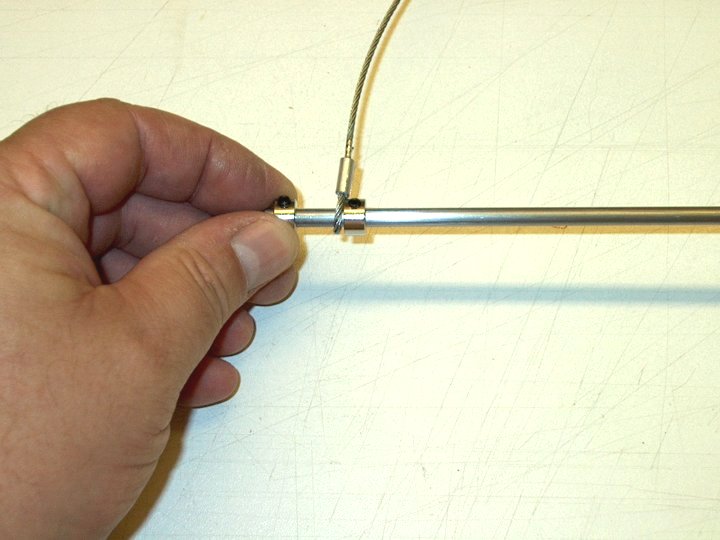
16 - The wire is pulled tight so that the loop can just fit over the 3/16" axle shaft
17.jpg
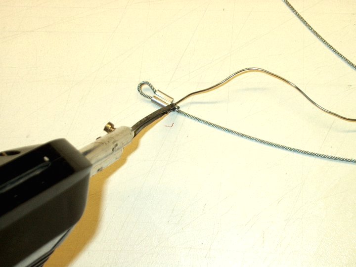
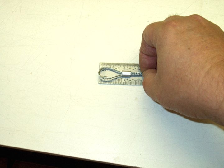
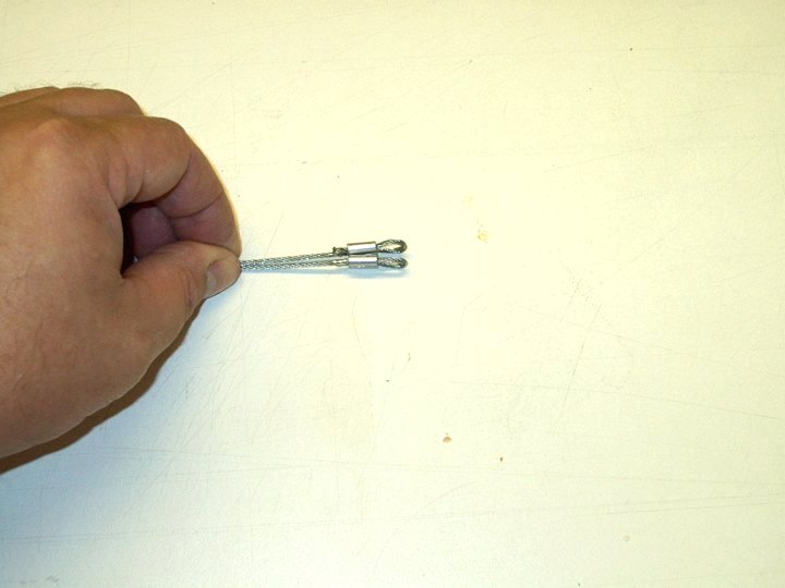
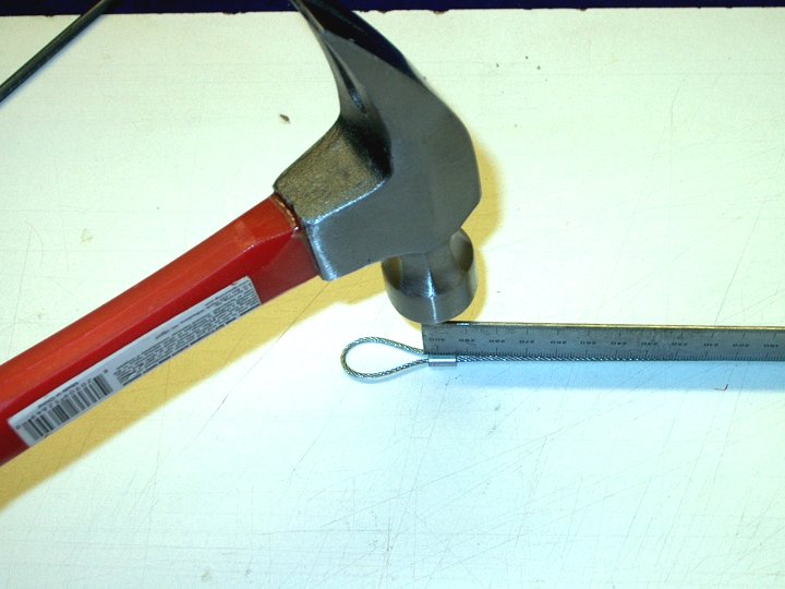
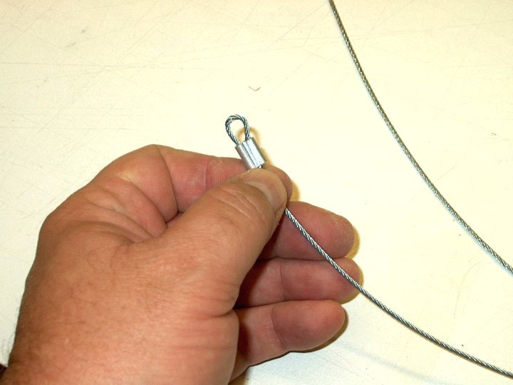
17 - Once crimped, you can solder the wire together for additional safety
18.jpg
18 - Wire shown crimped and soldered
19.jpg
19 - I used the side of a steel ruler to flatten the center of the ferrel and crimp it as shown
20.jpg
20 - Photo shows a closeup of the crimp
21.jpg
21 - A second ferrel is slid over the wire, then loosely looped back
22.jpg
22 - A third ferrel is slipped over the other end of the cable and the wire is passed through to make a large loop
23.jpg
23 - The center ferrel is shown in the photo on the left with the space between the two ferrels measured as seen
24.jpg
24 - The center Ferrel is also adjusted so a 1" loop extends past it as shown below
25.jpg
25 - Masking tape is used to hold the center loop and wires in position. Do not crip the center yet
26.jpg
26 - The third end ferrel is adjusted over the wire to the same space of 12" between it and the center ferrel
27.jpg
27 - The end is adjusted to fit over the 3/16" shaft, then it is crimped in place
28.jpg
28 - The other end ferrel shown crimped and the wires have been soldered
29.jpg
29 - Both ends shown even to eachother with similar sized loops
30.jpg
30 - Tape is removed from the center ferrel and it is slid up the wire to form a 1" long loop
31.jpg
31 - keep the two end loops together so the center loop is not made lobsided, then crimp the center ferrel as shown
32.jpg
32 - Wire completed with two ends and a center loop
33.jpg
33 - Once the wing set, use extra epoxy to fill any small gaps. One of the loops is slid over the shaft
34.jpg
34 - The wire loop is tightly retained with another Wheel Collar
35.jpg
35 - Two pieces of 3/16" inside diameter brass tube are cut to about 1/2" in length
36.jpg
36 - The tube is slid over the shaft
37.jpg
37 - Both brass tubes are installed on the shaft
38.jpg
38 - Slide another wheel collar on the shaft
39.jpg
39 - The other wire end is installed on the shaft
40.jpg
40 - Another wheel collar is loosely installed as shown
41.jpg
41 - The second wheel is installed on the shaft
42.jpg
42 - The final wheel collar is installed and tightened flush to the shaft end
43.jpg
43 - The inside wheel collar is tightened against the wheel, but make sure it can spin freely. Finally, tighten the inside wheel collar tight against the wire loop
44.jpg
44 - Once the inside wheel collars are tightened, remove the one outside collar and wheel
45.jpg
45 - The right wheel was removed so could more easily measure the distance between the two inside wheel collars. The distance is shown below as 10 1/2"
46.jpg
46 - Make a center line using a marker at half the distance between the two collars, in this case 5 1/4"
47.jpg
47 - Push the brass tube up against your mark, tape it in place so it doesn't move around and draw a full circle around the center line
48.jpg
48 - With both brass tubes pushed to the right of center, epoxy is applied to the shaft on the left side of the center mark
49.jpg
49 - The brass tube is slid past center and over the epoxy, then the excess epoxy is cleaned. Glue is applied to the right and the right side tube is slid over the glue back and forth until it fills inside, then the excess epoxy is removed from the right side tube
50.jpg
50 - Position the two brass tubes evenly on each side of the center line with about a 3/16" thick space between them as shown. Let the epoxy set up
51.jpg
51 - Bungee Dolly shown completed and ready to use
52.jpg
52 - The dolly should hang centered
53.jpg
53 - A 25-30' length of 1/8" wall x 1/2" bungee and stakes to secure the line are required for the assembly
54.jpg
54 - The dolly bungee system is shown
55.jpg
55 - A bungee release pedal is required and is covered in another build
56.jpg
56 - The towhook of the aircraft is hooked at the center of the Dolly axle, between the two brass tubes. The front loop of the Dolly is attached to the bungee cord using a 1/8" Quick Link
57.jpg
57 - The pedal is connected at the rear
58.jpg
58 - The bungee system shown hooked up to an aircraft. This completes the construction of a Dolly Bungee Launcher System


This Website and all documents herin are Copyright © 2012 www.scalerocketry.com - All rights reserved.